EP3782586B1 - Matrix implant - Google Patents
Matrix implant Download PDFInfo
- Publication number
- EP3782586B1 EP3782586B1 EP20186989.8A EP20186989A EP3782586B1 EP 3782586 B1 EP3782586 B1 EP 3782586B1 EP 20186989 A EP20186989 A EP 20186989A EP 3782586 B1 EP3782586 B1 EP 3782586B1
- Authority
- EP
- European Patent Office
- Prior art keywords
- implant
- struts
- support struts
- matrix
- guide pin
- Prior art date
- Legal status (The legal status is an assumption and is not a legal conclusion. Google has not performed a legal analysis and makes no representation as to the accuracy of the status listed.)
- Active
Links
Images




Classifications
-
- A—HUMAN NECESSITIES
- A61—MEDICAL OR VETERINARY SCIENCE; HYGIENE
- A61B—DIAGNOSIS; SURGERY; IDENTIFICATION
- A61B17/00—Surgical instruments, devices or methods
- A61B17/56—Surgical instruments or methods for treatment of bones or joints; Devices specially adapted therefor
- A61B17/58—Surgical instruments or methods for treatment of bones or joints; Devices specially adapted therefor for osteosynthesis, e.g. bone plates, screws or setting implements
- A61B17/68—Internal fixation devices, including fasteners and spinal fixators, even if a part thereof projects from the skin
- A61B17/84—Fasteners therefor or fasteners being internal fixation devices
-
- A—HUMAN NECESSITIES
- A61—MEDICAL OR VETERINARY SCIENCE; HYGIENE
- A61B—DIAGNOSIS; SURGERY; IDENTIFICATION
- A61B17/00—Surgical instruments, devices or methods
- A61B17/56—Surgical instruments or methods for treatment of bones or joints; Devices specially adapted therefor
- A61B17/58—Surgical instruments or methods for treatment of bones or joints; Devices specially adapted therefor for osteosynthesis, e.g. bone plates, screws or setting implements
- A61B17/68—Internal fixation devices, including fasteners and spinal fixators, even if a part thereof projects from the skin
- A61B17/70—Spinal positioners or stabilisers, e.g. stabilisers comprising fluid filler in an implant
- A61B17/7055—Spinal positioners or stabilisers, e.g. stabilisers comprising fluid filler in an implant connected to sacrum, pelvis or skull
-
- A—HUMAN NECESSITIES
- A61—MEDICAL OR VETERINARY SCIENCE; HYGIENE
- A61F—FILTERS IMPLANTABLE INTO BLOOD VESSELS; PROSTHESES; DEVICES PROVIDING PATENCY TO, OR PREVENTING COLLAPSING OF, TUBULAR STRUCTURES OF THE BODY, e.g. STENTS; ORTHOPAEDIC, NURSING OR CONTRACEPTIVE DEVICES; FOMENTATION; TREATMENT OR PROTECTION OF EYES OR EARS; BANDAGES, DRESSINGS OR ABSORBENT PADS; FIRST-AID KITS
- A61F2/00—Filters implantable into blood vessels; Prostheses, i.e. artificial substitutes or replacements for parts of the body; Appliances for connecting them with the body; Devices providing patency to, or preventing collapsing of, tubular structures of the body, e.g. stents
- A61F2/02—Prostheses implantable into the body
- A61F2/30—Joints
- A61F2/30767—Special external or bone-contacting surface, e.g. coating for improving bone ingrowth
-
- A—HUMAN NECESSITIES
- A61—MEDICAL OR VETERINARY SCIENCE; HYGIENE
- A61F—FILTERS IMPLANTABLE INTO BLOOD VESSELS; PROSTHESES; DEVICES PROVIDING PATENCY TO, OR PREVENTING COLLAPSING OF, TUBULAR STRUCTURES OF THE BODY, e.g. STENTS; ORTHOPAEDIC, NURSING OR CONTRACEPTIVE DEVICES; FOMENTATION; TREATMENT OR PROTECTION OF EYES OR EARS; BANDAGES, DRESSINGS OR ABSORBENT PADS; FIRST-AID KITS
- A61F2/00—Filters implantable into blood vessels; Prostheses, i.e. artificial substitutes or replacements for parts of the body; Appliances for connecting them with the body; Devices providing patency to, or preventing collapsing of, tubular structures of the body, e.g. stents
- A61F2/02—Prostheses implantable into the body
- A61F2/30—Joints
- A61F2/44—Joints for the spine, e.g. vertebrae or spinal discs
-
- A—HUMAN NECESSITIES
- A61—MEDICAL OR VETERINARY SCIENCE; HYGIENE
- A61F—FILTERS IMPLANTABLE INTO BLOOD VESSELS; PROSTHESES; DEVICES PROVIDING PATENCY TO, OR PREVENTING COLLAPSING OF, TUBULAR STRUCTURES OF THE BODY, e.g. STENTS; ORTHOPAEDIC, NURSING OR CONTRACEPTIVE DEVICES; FOMENTATION; TREATMENT OR PROTECTION OF EYES OR EARS; BANDAGES, DRESSINGS OR ABSORBENT PADS; FIRST-AID KITS
- A61F2/00—Filters implantable into blood vessels; Prostheses, i.e. artificial substitutes or replacements for parts of the body; Appliances for connecting them with the body; Devices providing patency to, or preventing collapsing of, tubular structures of the body, e.g. stents
- A61F2/02—Prostheses implantable into the body
- A61F2/28—Bones
- A61F2002/2835—Bone graft implants for filling a bony defect or an endoprosthesis cavity, e.g. by synthetic material or biological material
- A61F2002/2839—Bone plugs or bone graft dowels
-
- A—HUMAN NECESSITIES
- A61—MEDICAL OR VETERINARY SCIENCE; HYGIENE
- A61F—FILTERS IMPLANTABLE INTO BLOOD VESSELS; PROSTHESES; DEVICES PROVIDING PATENCY TO, OR PREVENTING COLLAPSING OF, TUBULAR STRUCTURES OF THE BODY, e.g. STENTS; ORTHOPAEDIC, NURSING OR CONTRACEPTIVE DEVICES; FOMENTATION; TREATMENT OR PROTECTION OF EYES OR EARS; BANDAGES, DRESSINGS OR ABSORBENT PADS; FIRST-AID KITS
- A61F2/00—Filters implantable into blood vessels; Prostheses, i.e. artificial substitutes or replacements for parts of the body; Appliances for connecting them with the body; Devices providing patency to, or preventing collapsing of, tubular structures of the body, e.g. stents
- A61F2/02—Prostheses implantable into the body
- A61F2/30—Joints
- A61F2002/30001—Additional features of subject-matter classified in A61F2/28, A61F2/30 and subgroups thereof
- A61F2002/30003—Material related properties of the prosthesis or of a coating on the prosthesis
- A61F2002/30004—Material related properties of the prosthesis or of a coating on the prosthesis the prosthesis being made from materials having different values of a given property at different locations within the same prosthesis
- A61F2002/30011—Material related properties of the prosthesis or of a coating on the prosthesis the prosthesis being made from materials having different values of a given property at different locations within the same prosthesis differing in porosity
-
- A—HUMAN NECESSITIES
- A61—MEDICAL OR VETERINARY SCIENCE; HYGIENE
- A61F—FILTERS IMPLANTABLE INTO BLOOD VESSELS; PROSTHESES; DEVICES PROVIDING PATENCY TO, OR PREVENTING COLLAPSING OF, TUBULAR STRUCTURES OF THE BODY, e.g. STENTS; ORTHOPAEDIC, NURSING OR CONTRACEPTIVE DEVICES; FOMENTATION; TREATMENT OR PROTECTION OF EYES OR EARS; BANDAGES, DRESSINGS OR ABSORBENT PADS; FIRST-AID KITS
- A61F2/00—Filters implantable into blood vessels; Prostheses, i.e. artificial substitutes or replacements for parts of the body; Appliances for connecting them with the body; Devices providing patency to, or preventing collapsing of, tubular structures of the body, e.g. stents
- A61F2/02—Prostheses implantable into the body
- A61F2/30—Joints
- A61F2002/30001—Additional features of subject-matter classified in A61F2/28, A61F2/30 and subgroups thereof
- A61F2002/30108—Shapes
- A61F2002/3011—Cross-sections or two-dimensional shapes
- A61F2002/30112—Rounded shapes, e.g. with rounded corners
- A61F2002/30113—Rounded shapes, e.g. with rounded corners circular
- A61F2002/30115—Rounded shapes, e.g. with rounded corners circular circular-O-shaped
-
- A—HUMAN NECESSITIES
- A61—MEDICAL OR VETERINARY SCIENCE; HYGIENE
- A61F—FILTERS IMPLANTABLE INTO BLOOD VESSELS; PROSTHESES; DEVICES PROVIDING PATENCY TO, OR PREVENTING COLLAPSING OF, TUBULAR STRUCTURES OF THE BODY, e.g. STENTS; ORTHOPAEDIC, NURSING OR CONTRACEPTIVE DEVICES; FOMENTATION; TREATMENT OR PROTECTION OF EYES OR EARS; BANDAGES, DRESSINGS OR ABSORBENT PADS; FIRST-AID KITS
- A61F2/00—Filters implantable into blood vessels; Prostheses, i.e. artificial substitutes or replacements for parts of the body; Appliances for connecting them with the body; Devices providing patency to, or preventing collapsing of, tubular structures of the body, e.g. stents
- A61F2/02—Prostheses implantable into the body
- A61F2/30—Joints
- A61F2002/30001—Additional features of subject-matter classified in A61F2/28, A61F2/30 and subgroups thereof
- A61F2002/30108—Shapes
- A61F2002/3011—Cross-sections or two-dimensional shapes
- A61F2002/30138—Convex polygonal shapes
- A61F2002/30149—Convex polygonal shapes pentagonal
-
- A—HUMAN NECESSITIES
- A61—MEDICAL OR VETERINARY SCIENCE; HYGIENE
- A61F—FILTERS IMPLANTABLE INTO BLOOD VESSELS; PROSTHESES; DEVICES PROVIDING PATENCY TO, OR PREVENTING COLLAPSING OF, TUBULAR STRUCTURES OF THE BODY, e.g. STENTS; ORTHOPAEDIC, NURSING OR CONTRACEPTIVE DEVICES; FOMENTATION; TREATMENT OR PROTECTION OF EYES OR EARS; BANDAGES, DRESSINGS OR ABSORBENT PADS; FIRST-AID KITS
- A61F2/00—Filters implantable into blood vessels; Prostheses, i.e. artificial substitutes or replacements for parts of the body; Appliances for connecting them with the body; Devices providing patency to, or preventing collapsing of, tubular structures of the body, e.g. stents
- A61F2/02—Prostheses implantable into the body
- A61F2/30—Joints
- A61F2002/30001—Additional features of subject-matter classified in A61F2/28, A61F2/30 and subgroups thereof
- A61F2002/30108—Shapes
- A61F2002/3011—Cross-sections or two-dimensional shapes
- A61F2002/30138—Convex polygonal shapes
- A61F2002/30153—Convex polygonal shapes rectangular
-
- A—HUMAN NECESSITIES
- A61—MEDICAL OR VETERINARY SCIENCE; HYGIENE
- A61F—FILTERS IMPLANTABLE INTO BLOOD VESSELS; PROSTHESES; DEVICES PROVIDING PATENCY TO, OR PREVENTING COLLAPSING OF, TUBULAR STRUCTURES OF THE BODY, e.g. STENTS; ORTHOPAEDIC, NURSING OR CONTRACEPTIVE DEVICES; FOMENTATION; TREATMENT OR PROTECTION OF EYES OR EARS; BANDAGES, DRESSINGS OR ABSORBENT PADS; FIRST-AID KITS
- A61F2/00—Filters implantable into blood vessels; Prostheses, i.e. artificial substitutes or replacements for parts of the body; Appliances for connecting them with the body; Devices providing patency to, or preventing collapsing of, tubular structures of the body, e.g. stents
- A61F2/02—Prostheses implantable into the body
- A61F2/30—Joints
- A61F2002/30001—Additional features of subject-matter classified in A61F2/28, A61F2/30 and subgroups thereof
- A61F2002/30108—Shapes
- A61F2002/3011—Cross-sections or two-dimensional shapes
- A61F2002/30138—Convex polygonal shapes
- A61F2002/30154—Convex polygonal shapes square
-
- A—HUMAN NECESSITIES
- A61—MEDICAL OR VETERINARY SCIENCE; HYGIENE
- A61F—FILTERS IMPLANTABLE INTO BLOOD VESSELS; PROSTHESES; DEVICES PROVIDING PATENCY TO, OR PREVENTING COLLAPSING OF, TUBULAR STRUCTURES OF THE BODY, e.g. STENTS; ORTHOPAEDIC, NURSING OR CONTRACEPTIVE DEVICES; FOMENTATION; TREATMENT OR PROTECTION OF EYES OR EARS; BANDAGES, DRESSINGS OR ABSORBENT PADS; FIRST-AID KITS
- A61F2/00—Filters implantable into blood vessels; Prostheses, i.e. artificial substitutes or replacements for parts of the body; Appliances for connecting them with the body; Devices providing patency to, or preventing collapsing of, tubular structures of the body, e.g. stents
- A61F2/02—Prostheses implantable into the body
- A61F2/30—Joints
- A61F2002/30001—Additional features of subject-matter classified in A61F2/28, A61F2/30 and subgroups thereof
- A61F2002/30108—Shapes
- A61F2002/3011—Cross-sections or two-dimensional shapes
- A61F2002/30138—Convex polygonal shapes
- A61F2002/30156—Convex polygonal shapes triangular
-
- A—HUMAN NECESSITIES
- A61—MEDICAL OR VETERINARY SCIENCE; HYGIENE
- A61F—FILTERS IMPLANTABLE INTO BLOOD VESSELS; PROSTHESES; DEVICES PROVIDING PATENCY TO, OR PREVENTING COLLAPSING OF, TUBULAR STRUCTURES OF THE BODY, e.g. STENTS; ORTHOPAEDIC, NURSING OR CONTRACEPTIVE DEVICES; FOMENTATION; TREATMENT OR PROTECTION OF EYES OR EARS; BANDAGES, DRESSINGS OR ABSORBENT PADS; FIRST-AID KITS
- A61F2/00—Filters implantable into blood vessels; Prostheses, i.e. artificial substitutes or replacements for parts of the body; Appliances for connecting them with the body; Devices providing patency to, or preventing collapsing of, tubular structures of the body, e.g. stents
- A61F2/02—Prostheses implantable into the body
- A61F2/30—Joints
- A61F2002/30001—Additional features of subject-matter classified in A61F2/28, A61F2/30 and subgroups thereof
- A61F2002/30108—Shapes
- A61F2002/3011—Cross-sections or two-dimensional shapes
- A61F2002/30159—Concave polygonal shapes
- A61F2002/30171—Concave polygonal shapes rosette- or star-shaped
-
- A—HUMAN NECESSITIES
- A61—MEDICAL OR VETERINARY SCIENCE; HYGIENE
- A61F—FILTERS IMPLANTABLE INTO BLOOD VESSELS; PROSTHESES; DEVICES PROVIDING PATENCY TO, OR PREVENTING COLLAPSING OF, TUBULAR STRUCTURES OF THE BODY, e.g. STENTS; ORTHOPAEDIC, NURSING OR CONTRACEPTIVE DEVICES; FOMENTATION; TREATMENT OR PROTECTION OF EYES OR EARS; BANDAGES, DRESSINGS OR ABSORBENT PADS; FIRST-AID KITS
- A61F2/00—Filters implantable into blood vessels; Prostheses, i.e. artificial substitutes or replacements for parts of the body; Appliances for connecting them with the body; Devices providing patency to, or preventing collapsing of, tubular structures of the body, e.g. stents
- A61F2/02—Prostheses implantable into the body
- A61F2/30—Joints
- A61F2002/30001—Additional features of subject-matter classified in A61F2/28, A61F2/30 and subgroups thereof
- A61F2002/30108—Shapes
- A61F2002/3011—Cross-sections or two-dimensional shapes
- A61F2002/30159—Concave polygonal shapes
- A61F2002/30179—X-shaped
-
- A—HUMAN NECESSITIES
- A61—MEDICAL OR VETERINARY SCIENCE; HYGIENE
- A61F—FILTERS IMPLANTABLE INTO BLOOD VESSELS; PROSTHESES; DEVICES PROVIDING PATENCY TO, OR PREVENTING COLLAPSING OF, TUBULAR STRUCTURES OF THE BODY, e.g. STENTS; ORTHOPAEDIC, NURSING OR CONTRACEPTIVE DEVICES; FOMENTATION; TREATMENT OR PROTECTION OF EYES OR EARS; BANDAGES, DRESSINGS OR ABSORBENT PADS; FIRST-AID KITS
- A61F2/00—Filters implantable into blood vessels; Prostheses, i.e. artificial substitutes or replacements for parts of the body; Appliances for connecting them with the body; Devices providing patency to, or preventing collapsing of, tubular structures of the body, e.g. stents
- A61F2/02—Prostheses implantable into the body
- A61F2/30—Joints
- A61F2002/30001—Additional features of subject-matter classified in A61F2/28, A61F2/30 and subgroups thereof
- A61F2002/30316—The prosthesis having different structural features at different locations within the same prosthesis; Connections between prosthetic parts; Special structural features of bone or joint prostheses not otherwise provided for
- A61F2002/30535—Special structural features of bone or joint prostheses not otherwise provided for
- A61F2002/30593—Special structural features of bone or joint prostheses not otherwise provided for hollow
-
- A—HUMAN NECESSITIES
- A61—MEDICAL OR VETERINARY SCIENCE; HYGIENE
- A61F—FILTERS IMPLANTABLE INTO BLOOD VESSELS; PROSTHESES; DEVICES PROVIDING PATENCY TO, OR PREVENTING COLLAPSING OF, TUBULAR STRUCTURES OF THE BODY, e.g. STENTS; ORTHOPAEDIC, NURSING OR CONTRACEPTIVE DEVICES; FOMENTATION; TREATMENT OR PROTECTION OF EYES OR EARS; BANDAGES, DRESSINGS OR ABSORBENT PADS; FIRST-AID KITS
- A61F2/00—Filters implantable into blood vessels; Prostheses, i.e. artificial substitutes or replacements for parts of the body; Appliances for connecting them with the body; Devices providing patency to, or preventing collapsing of, tubular structures of the body, e.g. stents
- A61F2/02—Prostheses implantable into the body
- A61F2/30—Joints
- A61F2002/30001—Additional features of subject-matter classified in A61F2/28, A61F2/30 and subgroups thereof
- A61F2002/30316—The prosthesis having different structural features at different locations within the same prosthesis; Connections between prosthetic parts; Special structural features of bone or joint prostheses not otherwise provided for
- A61F2002/30535—Special structural features of bone or joint prostheses not otherwise provided for
- A61F2002/30604—Special structural features of bone or joint prostheses not otherwise provided for modular
-
- A—HUMAN NECESSITIES
- A61—MEDICAL OR VETERINARY SCIENCE; HYGIENE
- A61F—FILTERS IMPLANTABLE INTO BLOOD VESSELS; PROSTHESES; DEVICES PROVIDING PATENCY TO, OR PREVENTING COLLAPSING OF, TUBULAR STRUCTURES OF THE BODY, e.g. STENTS; ORTHOPAEDIC, NURSING OR CONTRACEPTIVE DEVICES; FOMENTATION; TREATMENT OR PROTECTION OF EYES OR EARS; BANDAGES, DRESSINGS OR ABSORBENT PADS; FIRST-AID KITS
- A61F2/00—Filters implantable into blood vessels; Prostheses, i.e. artificial substitutes or replacements for parts of the body; Appliances for connecting them with the body; Devices providing patency to, or preventing collapsing of, tubular structures of the body, e.g. stents
- A61F2/02—Prostheses implantable into the body
- A61F2/30—Joints
- A61F2002/30001—Additional features of subject-matter classified in A61F2/28, A61F2/30 and subgroups thereof
- A61F2002/30621—Features concerning the anatomical functioning or articulation of the prosthetic joint
- A61F2002/30622—Implant for fusing a joint or bone material
-
- A—HUMAN NECESSITIES
- A61—MEDICAL OR VETERINARY SCIENCE; HYGIENE
- A61F—FILTERS IMPLANTABLE INTO BLOOD VESSELS; PROSTHESES; DEVICES PROVIDING PATENCY TO, OR PREVENTING COLLAPSING OF, TUBULAR STRUCTURES OF THE BODY, e.g. STENTS; ORTHOPAEDIC, NURSING OR CONTRACEPTIVE DEVICES; FOMENTATION; TREATMENT OR PROTECTION OF EYES OR EARS; BANDAGES, DRESSINGS OR ABSORBENT PADS; FIRST-AID KITS
- A61F2/00—Filters implantable into blood vessels; Prostheses, i.e. artificial substitutes or replacements for parts of the body; Appliances for connecting them with the body; Devices providing patency to, or preventing collapsing of, tubular structures of the body, e.g. stents
- A61F2/02—Prostheses implantable into the body
- A61F2/30—Joints
- A61F2/30767—Special external or bone-contacting surface, e.g. coating for improving bone ingrowth
- A61F2/30771—Special external or bone-contacting surface, e.g. coating for improving bone ingrowth applied in original prostheses, e.g. holes or grooves
- A61F2002/30772—Apertures or holes, e.g. of circular cross section
- A61F2002/30777—Oblong apertures
-
- A—HUMAN NECESSITIES
- A61—MEDICAL OR VETERINARY SCIENCE; HYGIENE
- A61F—FILTERS IMPLANTABLE INTO BLOOD VESSELS; PROSTHESES; DEVICES PROVIDING PATENCY TO, OR PREVENTING COLLAPSING OF, TUBULAR STRUCTURES OF THE BODY, e.g. STENTS; ORTHOPAEDIC, NURSING OR CONTRACEPTIVE DEVICES; FOMENTATION; TREATMENT OR PROTECTION OF EYES OR EARS; BANDAGES, DRESSINGS OR ABSORBENT PADS; FIRST-AID KITS
- A61F2/00—Filters implantable into blood vessels; Prostheses, i.e. artificial substitutes or replacements for parts of the body; Appliances for connecting them with the body; Devices providing patency to, or preventing collapsing of, tubular structures of the body, e.g. stents
- A61F2/02—Prostheses implantable into the body
- A61F2/30—Joints
- A61F2/30767—Special external or bone-contacting surface, e.g. coating for improving bone ingrowth
- A61F2/30771—Special external or bone-contacting surface, e.g. coating for improving bone ingrowth applied in original prostheses, e.g. holes or grooves
- A61F2002/30841—Sharp anchoring protrusions for impaction into the bone, e.g. sharp pins, spikes
-
- A—HUMAN NECESSITIES
- A61—MEDICAL OR VETERINARY SCIENCE; HYGIENE
- A61F—FILTERS IMPLANTABLE INTO BLOOD VESSELS; PROSTHESES; DEVICES PROVIDING PATENCY TO, OR PREVENTING COLLAPSING OF, TUBULAR STRUCTURES OF THE BODY, e.g. STENTS; ORTHOPAEDIC, NURSING OR CONTRACEPTIVE DEVICES; FOMENTATION; TREATMENT OR PROTECTION OF EYES OR EARS; BANDAGES, DRESSINGS OR ABSORBENT PADS; FIRST-AID KITS
- A61F2/00—Filters implantable into blood vessels; Prostheses, i.e. artificial substitutes or replacements for parts of the body; Appliances for connecting them with the body; Devices providing patency to, or preventing collapsing of, tubular structures of the body, e.g. stents
- A61F2/02—Prostheses implantable into the body
- A61F2/30—Joints
- A61F2/30767—Special external or bone-contacting surface, e.g. coating for improving bone ingrowth
- A61F2002/3092—Special external or bone-contacting surface, e.g. coating for improving bone ingrowth having an open-celled or open-pored structure
-
- A—HUMAN NECESSITIES
- A61—MEDICAL OR VETERINARY SCIENCE; HYGIENE
- A61F—FILTERS IMPLANTABLE INTO BLOOD VESSELS; PROSTHESES; DEVICES PROVIDING PATENCY TO, OR PREVENTING COLLAPSING OF, TUBULAR STRUCTURES OF THE BODY, e.g. STENTS; ORTHOPAEDIC, NURSING OR CONTRACEPTIVE DEVICES; FOMENTATION; TREATMENT OR PROTECTION OF EYES OR EARS; BANDAGES, DRESSINGS OR ABSORBENT PADS; FIRST-AID KITS
- A61F2/00—Filters implantable into blood vessels; Prostheses, i.e. artificial substitutes or replacements for parts of the body; Appliances for connecting them with the body; Devices providing patency to, or preventing collapsing of, tubular structures of the body, e.g. stents
- A61F2/02—Prostheses implantable into the body
- A61F2/30—Joints
- A61F2/30767—Special external or bone-contacting surface, e.g. coating for improving bone ingrowth
- A61F2002/3093—Special external or bone-contacting surface, e.g. coating for improving bone ingrowth for promoting ingrowth of bone tissue
-
- A—HUMAN NECESSITIES
- A61—MEDICAL OR VETERINARY SCIENCE; HYGIENE
- A61F—FILTERS IMPLANTABLE INTO BLOOD VESSELS; PROSTHESES; DEVICES PROVIDING PATENCY TO, OR PREVENTING COLLAPSING OF, TUBULAR STRUCTURES OF THE BODY, e.g. STENTS; ORTHOPAEDIC, NURSING OR CONTRACEPTIVE DEVICES; FOMENTATION; TREATMENT OR PROTECTION OF EYES OR EARS; BANDAGES, DRESSINGS OR ABSORBENT PADS; FIRST-AID KITS
- A61F2/00—Filters implantable into blood vessels; Prostheses, i.e. artificial substitutes or replacements for parts of the body; Appliances for connecting them with the body; Devices providing patency to, or preventing collapsing of, tubular structures of the body, e.g. stents
- A61F2/02—Prostheses implantable into the body
- A61F2/30—Joints
- A61F2/3094—Designing or manufacturing processes
- A61F2/30942—Designing or manufacturing processes for designing or making customized prostheses, e.g. using templates, CT or NMR scans, finite-element analysis or CAD-CAM techniques
- A61F2002/30962—Designing or manufacturing processes for designing or making customized prostheses, e.g. using templates, CT or NMR scans, finite-element analysis or CAD-CAM techniques using stereolithography
-
- A—HUMAN NECESSITIES
- A61—MEDICAL OR VETERINARY SCIENCE; HYGIENE
- A61F—FILTERS IMPLANTABLE INTO BLOOD VESSELS; PROSTHESES; DEVICES PROVIDING PATENCY TO, OR PREVENTING COLLAPSING OF, TUBULAR STRUCTURES OF THE BODY, e.g. STENTS; ORTHOPAEDIC, NURSING OR CONTRACEPTIVE DEVICES; FOMENTATION; TREATMENT OR PROTECTION OF EYES OR EARS; BANDAGES, DRESSINGS OR ABSORBENT PADS; FIRST-AID KITS
- A61F2/00—Filters implantable into blood vessels; Prostheses, i.e. artificial substitutes or replacements for parts of the body; Appliances for connecting them with the body; Devices providing patency to, or preventing collapsing of, tubular structures of the body, e.g. stents
- A61F2/02—Prostheses implantable into the body
- A61F2/30—Joints
- A61F2/3094—Designing or manufacturing processes
- A61F2002/30985—Designing or manufacturing processes using three dimensional printing [3DP]
-
- A—HUMAN NECESSITIES
- A61—MEDICAL OR VETERINARY SCIENCE; HYGIENE
- A61F—FILTERS IMPLANTABLE INTO BLOOD VESSELS; PROSTHESES; DEVICES PROVIDING PATENCY TO, OR PREVENTING COLLAPSING OF, TUBULAR STRUCTURES OF THE BODY, e.g. STENTS; ORTHOPAEDIC, NURSING OR CONTRACEPTIVE DEVICES; FOMENTATION; TREATMENT OR PROTECTION OF EYES OR EARS; BANDAGES, DRESSINGS OR ABSORBENT PADS; FIRST-AID KITS
- A61F2/00—Filters implantable into blood vessels; Prostheses, i.e. artificial substitutes or replacements for parts of the body; Appliances for connecting them with the body; Devices providing patency to, or preventing collapsing of, tubular structures of the body, e.g. stents
- A61F2/02—Prostheses implantable into the body
- A61F2/30—Joints
- A61F2/30988—Other joints not covered by any of the groups A61F2/32 - A61F2/4425
- A61F2002/30995—Other joints not covered by any of the groups A61F2/32 - A61F2/4425 for sacro-iliac joints
-
- A—HUMAN NECESSITIES
- A61—MEDICAL OR VETERINARY SCIENCE; HYGIENE
- A61F—FILTERS IMPLANTABLE INTO BLOOD VESSELS; PROSTHESES; DEVICES PROVIDING PATENCY TO, OR PREVENTING COLLAPSING OF, TUBULAR STRUCTURES OF THE BODY, e.g. STENTS; ORTHOPAEDIC, NURSING OR CONTRACEPTIVE DEVICES; FOMENTATION; TREATMENT OR PROTECTION OF EYES OR EARS; BANDAGES, DRESSINGS OR ABSORBENT PADS; FIRST-AID KITS
- A61F2/00—Filters implantable into blood vessels; Prostheses, i.e. artificial substitutes or replacements for parts of the body; Appliances for connecting them with the body; Devices providing patency to, or preventing collapsing of, tubular structures of the body, e.g. stents
- A61F2/02—Prostheses implantable into the body
- A61F2/30—Joints
- A61F2/44—Joints for the spine, e.g. vertebrae or spinal discs
- A61F2002/4495—Joints for the spine, e.g. vertebrae or spinal discs having a fabric structure, e.g. made from wires or fibres
-
- A—HUMAN NECESSITIES
- A61—MEDICAL OR VETERINARY SCIENCE; HYGIENE
- A61F—FILTERS IMPLANTABLE INTO BLOOD VESSELS; PROSTHESES; DEVICES PROVIDING PATENCY TO, OR PREVENTING COLLAPSING OF, TUBULAR STRUCTURES OF THE BODY, e.g. STENTS; ORTHOPAEDIC, NURSING OR CONTRACEPTIVE DEVICES; FOMENTATION; TREATMENT OR PROTECTION OF EYES OR EARS; BANDAGES, DRESSINGS OR ABSORBENT PADS; FIRST-AID KITS
- A61F2310/00—Prostheses classified in A61F2/28 or A61F2/30 - A61F2/44 being constructed from or coated with a particular material
- A61F2310/00005—The prosthesis being constructed from a particular material
- A61F2310/00011—Metals or alloys
- A61F2310/00017—Iron- or Fe-based alloys, e.g. stainless steel
-
- A—HUMAN NECESSITIES
- A61—MEDICAL OR VETERINARY SCIENCE; HYGIENE
- A61F—FILTERS IMPLANTABLE INTO BLOOD VESSELS; PROSTHESES; DEVICES PROVIDING PATENCY TO, OR PREVENTING COLLAPSING OF, TUBULAR STRUCTURES OF THE BODY, e.g. STENTS; ORTHOPAEDIC, NURSING OR CONTRACEPTIVE DEVICES; FOMENTATION; TREATMENT OR PROTECTION OF EYES OR EARS; BANDAGES, DRESSINGS OR ABSORBENT PADS; FIRST-AID KITS
- A61F2310/00—Prostheses classified in A61F2/28 or A61F2/30 - A61F2/44 being constructed from or coated with a particular material
- A61F2310/00005—The prosthesis being constructed from a particular material
- A61F2310/00011—Metals or alloys
- A61F2310/00023—Titanium or titanium-based alloys, e.g. Ti-Ni alloys
-
- A—HUMAN NECESSITIES
- A61—MEDICAL OR VETERINARY SCIENCE; HYGIENE
- A61F—FILTERS IMPLANTABLE INTO BLOOD VESSELS; PROSTHESES; DEVICES PROVIDING PATENCY TO, OR PREVENTING COLLAPSING OF, TUBULAR STRUCTURES OF THE BODY, e.g. STENTS; ORTHOPAEDIC, NURSING OR CONTRACEPTIVE DEVICES; FOMENTATION; TREATMENT OR PROTECTION OF EYES OR EARS; BANDAGES, DRESSINGS OR ABSORBENT PADS; FIRST-AID KITS
- A61F2310/00—Prostheses classified in A61F2/28 or A61F2/30 - A61F2/44 being constructed from or coated with a particular material
- A61F2310/00389—The prosthesis being coated or covered with a particular material
- A61F2310/00395—Coating or prosthesis-covering structure made of metals or of alloys
- A61F2310/00407—Coating made of titanium or of Ti-based alloys
Definitions
- Embodiments of the invention relate generally to bone implants that can be used to fuse two bone segments together.
- the human hip girdle (see FIGS. 1 and 2 ) is made up of three large bones joined by three relatively immobile joints.
- One of the bones is called the sacrum and it lies at the bottom of the lumbar spine, where it connects with the L5 vertebra.
- the other two bones are commonly called “hip bones” and are technically referred to as the right ilium and-the left ilium.
- the sacrum connects with both hip bones at the sacroiliac joint (in shorthand, the SI-Joint).
- the SI-Joint functions in the transmission of forces from the spine to the lower extremities, and vice-versa.
- the SI-Joint has been described as a pain generator for up to 22 percent of lower back pain patients.
- sacroiliac joint fusion is typically indicated as surgical treatment, e.g., for degenerative sacroiliitis, inflammatory sacroiliitis, iatrogenic instability of the sacroiliac joint, osteitis condensans ilii, or traumatic fracture dislocation of the pelvis.
- screws and screws with plates are used for sacro-iliac fusion.
- the cartilage has to be removed from the "synovial joint" portion of the SI-Joint. This requires a large incision to approach the damaged, subluxed, dislocated, fractured, or degenerated joint. The large incision and removal of tissue can cause significant trauma to the patient, resulting in pain and increasing the time to heal after surgery.
- screw type implants tend to be susceptible to rotation and loosening, especially in joints that are subjected to torsional forces, such as the SI-Joint. Excessive movement of the implant after implantation may result in the failure of the implant to incorporate and fuse with the bone, which may result in the need to remove and replace the failed implant.
- US2012/296428 describes a matrix implant for the fixation or fusion of the SI-Joint.
- US 2003/181979 describes a matrix implant for the fixation or fusion of the SI-Joint.
- US 2013/296953 describes an implant for bone fixation.
- an implant for bone fusion or fixation that resists rotation, can be implanted using a minimally invasive procedure, and/or that can be used to rescue a failed implant.
- the present invention relates generally to bone implants that can be used to fuse two bone segments together.
- the present invention provides a matrix implant for the fixation or fusion of the SI-Joint according to claim 1.
- Preferred embodiments of the invention are set forth in the dependent claims. While the manufacturing, implantation methods and associated tools described herein do not form part of the invention, they are disclosed as they represent useful background for understanding the invention.
- the rectilinear cross-sectional profile is triangular.
- the rectilinear cross-sectional profile is rectangular or square.
- the elongate body is curved along the longitudinal axis from the proximal end to the distal end of the elongate body. In some embodiments, the elongate body has a curvature between about 5 and 45 degrees.
- the elongate body has a curvature between about 15 and 30 degrees.
- the guide pin receptacle has a circular opening adapted to securely receive a guide pin.
- the elongate body is coated with a titanium plasma spray.
- the elongate body is coated with hydroxyapatite.
- the elongate body is made of metal.
- the metal is titanium
- the metal comprises a lattice structure.
- the lattice structure is cubic.
- the lattice structure is hexagonal.
- the lattice structure comprises a plurality of beams with a diameter between about 100 to 1000 microns.
- the elongate body is made of a ceramic material.
- the elongate body is mode of a plastic material.
- the elongate body has a porous outer surface.
- all struts are covered in a porous surface.
- all struts are preferentially covered in a porous surface.
- the porous outer surface has a pore size between about 100 to 1000 microns.
- the thickness of the apex struts and the support struts is between about 1 to 5 mm.
- the first guide pin receptacle is located at the distal end of the elongate body.
- the first guide pin receptacle is located at the proximal end of the elongate body.
- the first guide pin receptacle is located at the distal end of the elongate body and a second guide pin receptacle is located at the proximal end of the body.
- the implant can further include a continuous cannula extending between the first guide pin receptacle and the second guide pin receptacle.
- a third guide pin receptacle is located between the first guide pin receptacle and the second guide pin receptacle.
- a plurality of pin receptacles are located between the first guide pin receptacle and the second guide pin receptacle.
- the oblique supports struts are arranged in an "X" configuration. In some embodiments, the oblique supports struts are arranged in a non-overlapping diagonal configuration.
- the apex and support struts are arranged and spaced to accept bone graft material from the outer surface toward the center of the implant.
- the graft material is autograft.
- the graft material is allograft.
- the graft material is bone morphogenetic protein.
- the implant does not have any struts that extend from the outer surface toward the center of the implant, thereby forming a cavity for receiving a graft material and/or guide pin.
- FIG. 3 and FIG. 4 illustrate straight implants 10 with a solid elongate body 12 that can be used for the fixation or fusion of two bone segments.
- the implant 10 shown in FIG. 3 is cylindrical and can optionally have screw threads along the exterior of the implant body.
- cylindrical screw type implants can suffer from excessive rotation.
- One solution to this problem is the implant 10 in FIG. 4 , which has a non-cylindrical cross-sectional area.
- the implant 10 can have a triangular cross-sectional area, although other rectilinear cross-sectional profiles may be used as well, including rectangular, hexagonal and the like.
- Non-cylindrical implants need not have a strict rectilinear cross-sectional profile in order to resist rotation.
- a cross-sectional area that is non-circular will generally suffice.
- FIG. 5 illustrates insertion of the implant 10 of FIG. 3 or FIG. 4 across the SI-Joint using a lateral approach that goes laterally through the ilium, across the SI-Joint, and into the sacrum.
- FIG. 6 illustrates insertion of the same implant across the SI-Joint using a postero-lateral approach entering from the posterior iliac spine of the ilium, angling through the SI-Joint, and terminating in the sacral alae. Many of the implants described herein can be inserted across the SI-Joint in a similar manner.
- an implant with an open frame structure that can be packed with bone graft material and/or a biologic aid, while providing enough strength to facilitate the fusion of a joint or two bone segments without implant bending or failure.
- each face or side of the elongate body 12 can be constructed using a matrix structure.
- the implant 10 has a rectilinear overall outer profile transverse to a longitudinal axis that extends through the length of the elongate body 12.
- Each corner or apex of elongate body 12 is formed with an apex strut 14 that extends between the proximal end 16 and the distal end 18 of the elongate body 12.
- FIG. 7B illustrates another embodiment of a matrix structure where the support struts 20 are arranged in an alternating diagonal and transverse pattern.
- the diagonal support struts on one face of the implant are all angled in the same direction such that the diagonal support struts are parallel to each other.
- the support struts 20 define triangular openings.
- FIG. 7C illustrates yet another embodiment of a matrix structure where the support struts 20 are arranged in an alternating diagonal and transverse pattern.
- the diagonal support struts are angled in an alternating pattern such that the diagonal support struts are oriented about 90 degrees to one another to form a zigzag pattern.
- the support struts 20 also define triangular openings.
- the fenestrations 22 can be triangular, square, rectangular or combinations of the above and can be arranged to form a matrix structure.
- the openings in FIGS. 7A-7B defined by the support struts 20 can be considered fenestrations 22.
- FIG. 7D illustrates another embodiment of a matrix structure, similar to the embodiment shown in FIG. 7A , with support struts 20 that extend diagonally between apex struts 14 in an "X" configuration.
- the implant 10 has a proximal guide pin receptacle 28 located at the proximal end of the implant, a distal guide pin receptacle 24 located at the distal end of the implant, and a plurality of internal guide pin receptacles 30 also located along the longitudinal axis of the implant.
- the internal guide pin receptacles 30 can be attached to the support struts 20 and/or apex struts 14.
- the fenestrations 34 can be positioned along the openings of the support struts, which allows the tube to support the support struts 20 while fenestrations promote bony ingrowth and allow the introduction of bone graft material through the implant.
- FIGS. 7G-7I illustrates another embodiment of a matrix structure that is similar to the embodiment shown in FIG. 7E .
- This embodiment also has "X" shaped support struts 20 and additional support struts 20 that extend transversely between the apex struts 14 at right angles.
- the support struts 20 and apex struts 14 in this embodiment have generally rectilinear cross-sectional profiles while the embodiment disclosed in FIG. 7E has generally circular support struts 20 and apex struts 14.
- the apex struts 14 can be chamfered to remove sharp edges and the apices of the implant.
- this embodiment can have a distal guide pin receptacle 24 and a proximal guide pin receptacle, but unlike some of the embodiments described above, can lack internal guide pin receptacles.
- the guide pin can instead be supported internally by the inherent cross-sectional geometry of the apex struts and/or support struts.
- the struts can have rectilinear, circular, or a combination of the two cross-sectional profiles. The use of the rectilinear struts may allow for the fabrication of the matrix implant by laser cutting a walled structure, while tubular struts may be welded together.
- a laser cut structure may be structurally stronger than a welded structure, which is important for supporting the large loads applied to the implant after implantation.
- the distal end 18 of the implant 10 can also have one or more openings 29 that allow graft material to be injected distally through the implant after implantation.
- any of the embodiments described herein can optionally have the internal guide pin receptacles, or omit the internal guide pin receptacles.
- FIG. 7H illustrates a cross-sectional view taken through the transverse struts
- FIG. 7I illustrates a cross-sectional view taken through the "X" shaped support struts.
- the implant including the apex struts and/or support struts of the matrix as well as the beams that form the microstructure, can have a variety of shapes.
- the beams and/or struts can have a cross-section that is rectilinear, curvilinear, or combinations of the two, as illustrated in FIGS. 9A-9D .
- the beams and/or struts can have a circular cross-section as shown in FIG. 9A , or a curvilinear cross-section as shown in FIGS. 9B and 9C , or a square or rectangular cross section as shown in FIG. 9D . It should be understood that the corners and edges of the beams and/or struts can be rounded off if desired.
- the implant can be made of a variety of materials.
- the implant can be made of a metal or metal alloy, such as titanium or steel, or a nonmetallic material such as ceramic or polymer.
- the implant material can have a certain lattice microstructure formed from the beam microparticles.
- the lattice microstructure of the apex strut, support struts and other parts of the implant can result in a rough or smooth surface texture, depending on the surface finishing techniques used, such as polishing or application of a metal plasma spray, and the size and shape of the beams that form the lattice microstructure.
- FIGS. 10A-10C illustrate various beam microstructures that can form the lattice microstructure.
- FIG. 10A-10C illustrate various beam microstructures that can form the lattice microstructure.
- FIGS. 11A-11D illustrate that the beams can have various sizes.
- FIGS. 11A-11D illustrate beams having a diameter of about 100, 200 microns, 350 microns, 500 microns, and 1000 microns. In other embodiments, the size of the beam can vary between 50 microns to 5000 microns.
- the matrix implant can be manufactured using a variety of techniques.
- the matrix implant can be 3-D printed using a rapid prototyping technique involving additive manufacturing, such as described in U.S. Patent Publication No. 2010/0161061 ,.
- the 3-D printed matrix implant can be made of a metal, polymer, or ceramic material.
- a metal powder such as titanium powder can be fused together to form the implant structure.
- Other techniques include cutting out the fenestrations or openings, using a laser for example, to form the apex struts and support struts, or using electric discharge machining (EDM) to create the matrixes or fenestrations.
- EDM electric discharge machining
- the implant can have a volume porosity between about 30 and 70 percent, with an average pore size between 100 and 1000 microns.
- the pores can be largely interconnected, largely unconnected, or a mix of interconnected and unconnected pores.
- the pores can be located throughout the material of the implant, including the apex struts and support struts, and on all or some of the strut surfaces, including the inner and outer implant surfaces.
- the fusion of the beam microparticles to form the struts can result in a porous, semi-porous, or nonporous structure, depending on the degree of fusion between the beam microparticles.
- the pores can be located in a porous coating that can be applied onto the implant.
- a porous coating can be applied using a titanium plasma spray process, or another metal plasma spray process.
- the coating can be applied to the outer surfaces of the implant, the interior surfaces of the implant, or both the outer and interior surfaces of the implant.
- the coating could be preferentially applied to the outer surface of a matrixed implant to provide bony ingrowth and ongrowth, and not applied to the inner portion of the implant to maximize bony through-growth within the implant.
- the coating can be applied preferentially from proximal to distal, or vice versa.
- the thickness of a porous coating can be between about 500 and 1,500 microns.
- a hydroxyapatite coating can also be applied to the implant.
- the porosity can be varied along the length of the implant.
- the thickness of the coating can be varied along the length of the implant.
- the thickness of the coating applied to the outer surface can be different than the thickness of the inner coating.
- the outer coating may be greater than the inner coating in some embodiments.
- the thickness of the inner and outer coatings can be the same.
- the apex struts 14 can be curved from the proximal end to the distal end of the apex strut 14, thereby resulting in a curved matrix implant 10 similar to the curved implants described in co-pending U.S. Provisional Application No. 62/052,318, filed September 18, 2014 and entitled "IMPLANTS FOR BONE FIXATION OR FUSION,".
- a matrix structure can be modular, as shown in FIG. 13 , which allows the length of the implant to be varied by the addition of additional repeating subunits during the design and/or fabrication of the implant.
- a modular matrix implant 130 can have a distal end portion 132, a proximal end portion 134, and one or more repeating internal portions 136.
- the distal end portion 132 can have a distal guide pin receptacle 138, and the proximal end portion 134 can have a proximal guide pin receptacle 136, much like the embodiments discussed above.
- the repeating internal portion 136 can have apex struts 140 and support struts 142, as described above.
- the support struts 142 can have an "X" configuration and can be located between two transverse support struts 144.
- the two transverse support struts 144 can be half the normal transverse support struts such that when two repeating internal portions 136 are joined together, the two half support struts merge to form a whole transverse support strut.
- the proximal and distal end portions 132, 134 can also have a coupling portion that is formed from half transverse support struts 144 that can be merged with the half transverse support struts 144 of the repeating internal portion 136.
- the repeating internal portion 136 can also have an internal guide pin receptacle 146.
- the length of the repeating internal portion 136 can be about 10 mm. In other embodiments, the length can be between about 5 and 25 mm. In some embodiments, the repeating internal portion 136 can have support struts that form half an "X", such that the repeating internal portions are arranged in an alternating pattern to form "X" shaped support struts. In some embodiments, the support struts are simply diagonal struts that extend across the length of the repeating internal portion.
- the curved implant illustrated in FIG. 12 may require modifications to the method of insertion protocols. Because the implant is curved, it may not be possible or desirable to attempt to hammer or tap the implant into the bone along a straight path using a straight guide pin, a straight drill, a straight broach and the like. Instead, it may be desirable to create and form a curved insertion path that matches the curvature of the implant.
- the tooling used to create the curved insertion path can have a radius of curvature that matches the radius of curvature of the implant.
- some or all of the tooling and the implant can have a matching radius of curvature.
- the tooling which can include a guide pin, a tool guide, a drill bit, a broach, and impact hammer and the like can be rotatably secured by an arm with a length equal to the radius of curvature, with one end of the arm attached to a pivot and the other end used to secure the tools and/or implant.
- the rotating arm can be used to drive a curved guide pin into the bone to create a curved path through the bone, such as the ilium and the sacrum.
- a relatively short drill bit with a lumen for receiving the guide pin can be disposed over the curved guide pin to drill out a curved pilot bore.
- the drill bit can be secured by the pivoting arm at the end of a curved guide and can be used to drill the curved pilot bore without the insertion of the curved guide pin.
- the curved implant can then be advanced over the curved guide pin and into the curved insertion path that is formed by the curved pilot bore.
- the curved implant can be held by the pivoting arm and inserted into the curved insertion path without the aid of a guide pin by rotating the curved arm.
- the curved pilot bore can be shaped using an appropriately shaped broach that matches the overall cross-sectional shape of the implant.
- a curved broach, or a short broach can be advanced over the curved guide pin if present, otherwise the curved broach or short broach can be held in the pivoting arm and advanced through the pilot bore by rotation of the pivoting arm. As the broach is advanced, it shapes the pilot bore into a shape that matches the shape of the implant.
- the curved implant can then be advanced over the curved guide pin and into the curved insertion path that is formed by the curved pilot bore.
- the curved implant can be held by the pivoting arm and inserted into the curved insertion path without the aid of a guide pin by rotating the curved arm.
- the implants described herein can be used to fuse any two bone segments, such as two bones that form a j oint or two bones resulting from a fracture.
Landscapes
- Health & Medical Sciences (AREA)
- Orthopedic Medicine & Surgery (AREA)
- Life Sciences & Earth Sciences (AREA)
- Engineering & Computer Science (AREA)
- Biomedical Technology (AREA)
- Neurology (AREA)
- Surgery (AREA)
- Public Health (AREA)
- Heart & Thoracic Surgery (AREA)
- Veterinary Medicine (AREA)
- Animal Behavior & Ethology (AREA)
- General Health & Medical Sciences (AREA)
- Medical Informatics (AREA)
- Nuclear Medicine, Radiotherapy & Molecular Imaging (AREA)
- Molecular Biology (AREA)
- Oral & Maxillofacial Surgery (AREA)
- Cardiology (AREA)
- Vascular Medicine (AREA)
- Transplantation (AREA)
- Neurosurgery (AREA)
- Prostheses (AREA)
- Surgical Instruments (AREA)
Description
- Embodiments of the invention relate generally to bone implants that can be used to fuse two bone segments together.
- Many types of hardware are available both for the fixation of bones that are fractured and for the fixation of bones that are to be fused (arthrodesed).
- For example, the human hip girdle (see
FIGS. 1 and 2 ) is made up of three large bones joined by three relatively immobile joints. One of the bones is called the sacrum and it lies at the bottom of the lumbar spine, where it connects with the L5 vertebra. The other two bones are commonly called "hip bones" and are technically referred to as the right ilium and-the left ilium. The sacrum connects with both hip bones at the sacroiliac joint (in shorthand, the SI-Joint). - The SI-Joint functions in the transmission of forces from the spine to the lower extremities, and vice-versa. The SI-Joint has been described as a pain generator for up to 22 percent of lower back pain patients.
- To relieve pain generated from the SI-Joint, sacroiliac joint fusion is typically indicated as surgical treatment, e.g., for degenerative sacroiliitis, inflammatory sacroiliitis, iatrogenic instability of the sacroiliac joint, osteitis condensans ilii, or traumatic fracture dislocation of the pelvis. Currently, screws and screws with plates are used for sacro-iliac fusion. At the same time the cartilage has to be removed from the "synovial joint" portion of the SI-Joint. This requires a large incision to approach the damaged, subluxed, dislocated, fractured, or degenerated joint. The large incision and removal of tissue can cause significant trauma to the patient, resulting in pain and increasing the time to heal after surgery.
- In addition, screw type implants tend to be susceptible to rotation and loosening, especially in joints that are subjected to torsional forces, such as the SI-Joint. Excessive movement of the implant after implantation may result in the failure of the implant to incorporate and fuse with the bone, which may result in the need to remove and replace the failed implant.
US2012/296428 describes a matrix implant for the fixation or fusion of the SI-Joint.US 2003/181979 describes a matrix implant for the fixation or fusion of the SI-Joint.US 2013/296953 describes an implant for bone fixation. - Consequently, it would be desirable to provide an implant for bone fusion or fixation that resists rotation, can be implanted using a minimally invasive procedure, and/or that can be used to rescue a failed implant.
- The present invention relates generally to bone implants that can be used to fuse two bone segments together.
- The present invention provides a matrix implant for the fixation or fusion of the SI-Joint according to
claim 1. Preferred embodiments of the invention are set forth in the dependent claims. While the manufacturing, implantation methods and associated tools described herein do not form part of the invention, they are disclosed as they represent useful background for understanding the invention. - In some embodiments, the rectilinear cross-sectional profile is triangular.
- In some embodiments, the rectilinear cross-sectional profile is rectangular or square.
- In some embodiments, the elongate body is curved along the longitudinal axis from the proximal end to the distal end of the elongate body. In some embodiments, the elongate body has a curvature between about 5 and 45 degrees.
- In some embodiments, the elongate body has a curvature between about 15 and 30 degrees.
- In some embodiments, the guide pin receptacle has a circular opening adapted to securely receive a guide pin.
- In some embodiments, the elongate body is coated with a titanium plasma spray.
- In some embodiments, the elongate body is coated with hydroxyapatite.
- In some embodiments, the elongate body is made of metal.
- In some embodiments, the metal is titanium.
- In some embodiments, the metal comprises a lattice structure.
- In some embodiments, the lattice structure is cubic.
- In some embodiments, the lattice structure is hexagonal.
- In some embodiments, the lattice structure comprises a plurality of beams with a diameter between about 100 to 1000 microns.
- In some embodiments, the elongate body is made of a ceramic material.
- In some embodiments, the elongate body is mode of a plastic material.
- In some embodiments, the elongate body has a porous outer surface.
- In some embodiments, all struts are covered in a porous surface.
- In some embodiments, all struts are preferentially covered in a porous surface.
- In some embodiments, the porous outer surface has a pore size between about 100 to 1000 microns.
- In some embodiments, the thickness of the apex struts and the support struts is between about 1 to 5 mm.
- In some embodiments, the first guide pin receptacle is located at the distal end of the elongate body.
- In some embodiments, the first guide pin receptacle is located at the proximal end of the elongate body.
- In some embodiments, the first guide pin receptacle is located at the distal end of the elongate body and a second guide pin receptacle is located at the proximal end of the body.
- In some embodiments, the implant can further include a continuous cannula extending between the first guide pin receptacle and the second guide pin receptacle.
- In some embodiments, a third guide pin receptacle is located between the first guide pin receptacle and the second guide pin receptacle.
- In some embodiments, a plurality of pin receptacles are located between the first guide pin receptacle and the second guide pin receptacle.
- In some embodiments, the oblique supports struts are arranged in an "X" configuration. In some embodiments, the oblique supports struts are arranged in a non-overlapping diagonal configuration.
- In some embodiments, the apex and support struts are arranged and spaced to accept bone graft material from the outer surface toward the center of the implant.
- In some embodiments, the graft material is autograft.
- In some embodiments, the graft material is allograft.
- In some embodiments, the graft material is bone morphogenetic protein.
- In some embodiments, the implant does not have any struts that extend from the outer surface toward the center of the implant, thereby forming a cavity for receiving a graft material and/or guide pin.
- The novel features of the invention are set forth with particularity in the claims that follow. A better understanding of the features and advantages of the present invention will be obtained by reference to the following detailed description that sets forth illustrative embodiments, in which the principles of the invention are utilized, and the accompanying drawings of which:
-
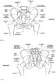
FIGS. 1 and 2 are, respectively, anterior and posterior anatomic views of the human hip girdle comprising the sacrum and the hip bones (the right ilium, and the left ilium), the sacrum being connected with both hip bones at the sacroiliac joint (in shorthand, the SI-Joint). -
FIGS. 3 and 4 are embodiments of various straight implants that can be used for the fusion or fixation of a joint or two bone segments. -
FIG. 5 illustrates an axial section view of the SI-Joint with an implant for the fixation of the SI-Joint using a lateral approach that goes laterally through the ilium, the SI-Joint, and into the sacrum S1. -
FIG. 6 illustrates an axial section view of the SI-Joint with an implant for the fixation of the SI-Joint using a postero-lateral approach entering from the posterior iliac spine of the ilium, angling through the SI-Joint, and terminating in the sacral alae. -
FIGS. 7A-7C illustrate various embodiments of implants having a matrix structure formed from a plurality of struts. -
FIGS. 7D-7F illustrate various embodiments of implants having a matrix structure with a plurality of pin receptacles. -
FIGS. 7G-7I illustrate another embodiment of an implant having a matrix structure from various angles and cross-sections. -
FIG. 8 illustrates an embodiment of a fenestrated implant. -
FIGS. 9A-9D illustrate various cross-sectional profiles of the implant microstructure, which can be formed with beam microstructures of varying geometries. -
FIGS. 10A-10C illustrate various alternative beam microstructures. -
FIGS. 11A-11D illustrate various sizes for the beams that form the implant microstructure. -
FIG. 12 illustrates an embodiment of a curved matrix implant. -
FIG. 13 illustrates of a modular matrix implant. -
FIG. 3 and FIG. 4 illustratestraight implants 10 with a solidelongate body 12 that can be used for the fixation or fusion of two bone segments. Theimplant 10 shown inFIG. 3 is cylindrical and can optionally have screw threads along the exterior of the implant body. As mentioned above, cylindrical screw type implants can suffer from excessive rotation. One solution to this problem is theimplant 10 inFIG. 4 , which has a non-cylindrical cross-sectional area. For example, as shown, theimplant 10 can have a triangular cross-sectional area, although other rectilinear cross-sectional profiles may be used as well, including rectangular, hexagonal and the like. Non-cylindrical implants need not have a strict rectilinear cross-sectional profile in order to resist rotation. A cross-sectional area that is non-circular will generally suffice. -
FIG. 5 illustrates insertion of theimplant 10 ofFIG. 3 or FIG. 4 across the SI-Joint using a lateral approach that goes laterally through the ilium, across the SI-Joint, and into the sacrum.FIG. 6 illustrates insertion of the same implant across the SI-Joint using a postero-lateral approach entering from the posterior iliac spine of the ilium, angling through the SI-Joint, and terminating in the sacral alae. Many of the implants described herein can be inserted across the SI-Joint in a similar manner. - In some embodiments, it may be desirable to provide an implant with an open frame structure that can be packed with bone graft material and/or a biologic aid, while providing enough strength to facilitate the fusion of a joint or two bone segments without implant bending or failure.
- One way to provide an open frame structure is to construct the
elongate body 12 of theimplant 10 using a matrix structure, as illustrated inFIGS. 7A-7C and7G-7I . In some embodiments, each face or side of theelongate body 12 can be constructed using a matrix structure. Theimplant 10 has a rectilinear overall outer profile transverse to a longitudinal axis that extends through the length of theelongate body 12. Each corner or apex ofelongate body 12 is formed with anapex strut 14 that extends between theproximal end 16 and thedistal end 18 of theelongate body 12. An implant with a triangular overall cross-sectional profile has three apex struts, while an implant with a square or rectangular overall cross-sectional profile has four apex struts, and so on. To form the faces of the implant, support struts 20 are arranged in various matrix structures. - For example,
FIG. 7A illustrates one embodiment of a matrix structure where the support struts 20 extend diagonally between twoapex struts 14 and cross each other in an "X" configuration such that the support struts 20 define triangular and square openings. Additional transverse support struts that extend between two apex struts at a right angle to both apex struts can also be added. The transverse support struts can be positioned between the "X" support struts and/or can be positioned to cross the middle or intersection of the "X" support struts. -
FIG. 7B illustrates another embodiment of a matrix structure where the support struts 20 are arranged in an alternating diagonal and transverse pattern. In this embodiment, the diagonal support struts on one face of the implant are all angled in the same direction such that the diagonal support struts are parallel to each other. The support struts 20 define triangular openings. -
FIG. 7C illustrates yet another embodiment of a matrix structure where the support struts 20 are arranged in an alternating diagonal and transverse pattern. In this embodiment, the diagonal support struts are angled in an alternating pattern such that the diagonal support struts are oriented about 90 degrees to one another to form a zigzag pattern. The support struts 20 also define triangular openings. - The various matrix structures can provide different levels of resistance to various forces that the implant will be subjected to, including compressive, tensile, shear, bending, and torsional forces.
-
FIG. 8 illustrates an alternative to using a matrix structure to provide openings. Theimplant 10 can have anelongate body 12 withfenestrations 22. Thefenestrations 22 can be circular as shown, and can be of different sizes in, for example, an alternating pattern of large and small fenestrations. Thefenestrations 22 can alternatively be rectilinear in shape, such as triangular, square, rectangular, and the like, or curvilinear, such as elliptical, oval, or circular. - In some embodiments, the
fenestrations 22 can be triangular, square, rectangular or combinations of the above and can be arranged to form a matrix structure. In other words, the openings inFIGS. 7A-7B defined by the support struts 20 can be considered fenestrations 22. - The walls of
elongate body 12 can be planar and, as described above, can be formed from support struts 20 and/orfenestrations 22, as shown inFIGS. 7G-7I , for example. Using planar walls to form theelongate body 12 can result in a hollow cavity with the same or similar cross-sectional profile as the overall implant. For example, an implant with a triangular overall cross-sectional profile can also have a cavity with a triangular cross-sectional profile. The thickness of the walls and the apex struts and support struts can be between about 1 mm and 5 mm, or between about 1 and 3 mm. In addition, the distal ends of the walls can be tapered. - To facilitate the use of a traditional guide pin with these implants, the distal end of the implant can include a distal
guide pin receptacle 24 with anopening 26 that is sized and shaped to receive a guide pin, as shown inFIGS. 7A-8 . For example, theopening 26 can be circular to receive a typical guide pin. In some embodiments, the proximal end can additionally or alternatively have a proximal guide pin receptacle with an opening sized and shaped to receive a guide pin. In some embodiments, a continuous cannula can extend from the proximal guide pin receptacle to the distal guide pin receptacle. In some embodiments, multiple individual and colinear guide pin receptacles can be present within the implant body between the proximal guide pin receptacle and the distal guide pin receptacle. - For example,
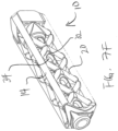
FIG. 7D illustrates another embodiment of a matrix structure, similar to the embodiment shown inFIG. 7A , with support struts 20 that extend diagonally between apex struts 14 in an "X" configuration. However, in this embodiment, theimplant 10 has a proximalguide pin receptacle 28 located at the proximal end of the implant, a distalguide pin receptacle 24 located at the distal end of the implant, and a plurality of internalguide pin receptacles 30 also located along the longitudinal axis of the implant. The internalguide pin receptacles 30 can be attached to the support struts 20 and/or apex struts 14. As shown, the internalguide pin receptacles 30 are attached at the intersection points of the "X" shaped support struts 20. In addition to receiving the guide pin, the internalguide pin receptacles 30 can provide additional support and bracing to the matrix structure. -
FIG. 7E illustrates another embodiment of a matrix structure that is similar to the embodiment shown inFIG. 7D . Both embodiments have "X" shaped support struts 20 and a plurality of internalguide pin receptacles 30. However, this embodiment has additional support struts 20 that extend transversely between the apex struts 14 at right angles. The transverse support struts can be positioned between the "X" shaped support struts as shown, or can be integrated into the "X" shaped support struts. The transverse support struts can provide additional support and bracing to the matrix structure. -
FIG. 7F illustrates another embodiment of a matrix structure that is similar to the embodiment shown inFIG. 7D . However, instead of having a plurality of guide pin receptacles, theimplant 10 has a singleguide pin receptacle 32 that extends from the proximal end to the distal end of the implant. Thisguide pin receptacle 32 can be a tube or cannula that can be attached to the support struts 20. In some embodiments, the tube or cannula can also have a plurality offenestrations 34. In some embodiments, thefenestrations 34 can be positioned along the openings of the support struts, which allows the tube to support the support struts 20 while fenestrations promote bony ingrowth and allow the introduction of bone graft material through the implant. -
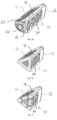
FIGS. 7G-7I illustrates another embodiment of a matrix structure that is similar to the embodiment shown inFIG. 7E . This embodiment also has "X" shaped support struts 20 and additional support struts 20 that extend transversely between the apex struts 14 at right angles. One difference between this embodiment and the embodiment illustrated inFIG. 7E is that the support struts 20 and apex struts 14 in this embodiment have generally rectilinear cross-sectional profiles while the embodiment disclosed inFIG. 7E has generally circular support struts 20 and apex struts 14. In some embodiments, the apex struts 14 can be chamfered to remove sharp edges and the apices of the implant. In addition, this embodiment can have a distalguide pin receptacle 24 and a proximal guide pin receptacle, but unlike some of the embodiments described above, can lack internal guide pin receptacles. The guide pin can instead be supported internally by the inherent cross-sectional geometry of the apex struts and/or support struts. The struts can have rectilinear, circular, or a combination of the two cross-sectional profiles. The use of the rectilinear struts may allow for the fabrication of the matrix implant by laser cutting a walled structure, while tubular struts may be welded together. A laser cut structure may be structurally stronger than a welded structure, which is important for supporting the large loads applied to the implant after implantation. Thedistal end 18 of theimplant 10 can also have one ormore openings 29 that allow graft material to be injected distally through the implant after implantation. In addition, any of the embodiments described herein can optionally have the internal guide pin receptacles, or omit the internal guide pin receptacles.FIG. 7H illustrates a cross-sectional view taken through the transverse struts, whileFIG. 7I illustrates a cross-sectional view taken through the "X" shaped support struts. - The implant, including the apex struts and/or support struts of the matrix as well as the beams that form the microstructure, can have a variety of shapes. For example, the beams and/or struts can have a cross-section that is rectilinear, curvilinear, or combinations of the two, as illustrated in
FIGS. 9A-9D . For example, the beams and/or struts can have a circular cross-section as shown inFIG. 9A , or a curvilinear cross-section as shown inFIGS. 9B and 9C , or a square or rectangular cross section as shown inFIG. 9D . It should be understood that the corners and edges of the beams and/or struts can be rounded off if desired. - The implant can be made of a variety of materials. For example, the implant can be made of a metal or metal alloy, such as titanium or steel, or a nonmetallic material such as ceramic or polymer. In some embodiments, the implant material can have a certain lattice microstructure formed from the beam microparticles. For example, the lattice microstructure of the apex strut, support struts and other parts of the implant can result in a rough or smooth surface texture, depending on the surface finishing techniques used, such as polishing or application of a metal plasma spray, and the size and shape of the beams that form the lattice microstructure. For example,
FIGS. 10A-10C illustrate various beam microstructures that can form the lattice microstructure.FIG. 10A illustrates a cubic beam structure, whileFIG. 10B illustrates a hexagonal beam structure, andFIG. 10C illustrates an octagonal beam structure. Other beam structures include tetragonal, rhombohedral, orthorhombic, monoclinic, and triclinic.FIGS. 11A-11D illustrate that the beams can have various sizes. For example,FIGS. 11A-11D illustrate beams having a diameter of about 100, 200 microns, 350 microns, 500 microns, and 1000 microns. In other embodiments, the size of the beam can vary between 50 microns to 5000 microns. - The matrix implant can be manufactured using a variety of techniques. For example, the matrix implant can be 3-D printed using a rapid prototyping technique involving additive manufacturing, such as described in
U.S. Patent Publication No. 2010/0161061 ,. The 3-D printed matrix implant can be made of a metal, polymer, or ceramic material. For example, a metal powder such as titanium powder can be fused together to form the implant structure. Other techniques include cutting out the fenestrations or openings, using a laser for example, to form the apex struts and support struts, or using electric discharge machining (EDM) to create the matrixes or fenestrations. - 3-D printing allows the porosity of the implant to be controlled. For example, the implant can have a volume porosity between about 30 and 70 percent, with an average pore size between 100 and 1000 microns. The pores can be largely interconnected, largely unconnected, or a mix of interconnected and unconnected pores. In some embodiments, the pores can be located throughout the material of the implant, including the apex struts and support struts, and on all or some of the strut surfaces, including the inner and outer implant surfaces. For example, the fusion of the beam microparticles to form the struts can result in a porous, semi-porous, or nonporous structure, depending on the degree of fusion between the beam microparticles. In other embodiments, the pores can be located in a porous coating that can be applied onto the implant. For example, a porous coating can be applied using a titanium plasma spray process, or another metal plasma spray process. The coating can be applied to the outer surfaces of the implant, the interior surfaces of the implant, or both the outer and interior surfaces of the implant. For example, the coating could be preferentially applied to the outer surface of a matrixed implant to provide bony ingrowth and ongrowth, and not applied to the inner portion of the implant to maximize bony through-growth within the implant. Also, the coating can be applied preferentially from proximal to distal, or vice versa. The thickness of a porous coating can be between about 500 and 1,500 microns. In addition or alternatively to the porous metal coating, a hydroxyapatite coating can also be applied to the implant. In some embodiments, the porosity can be varied along the length of the implant. In some embodiments, the thickness of the coating can be varied along the length of the implant. In some embodiments, the thickness of the coating applied to the outer surface can be different than the thickness of the inner coating. For example, the outer coating may be greater than the inner coating in some embodiments. In other embodiments, the thickness of the inner and outer coatings can be the same.
- In some embodiments, as illustrated in
FIG. 12 , the apex struts 14 can be curved from the proximal end to the distal end of theapex strut 14, thereby resulting in acurved matrix implant 10 similar to the curved implants described in co-pendingU.S. Provisional Application No. 62/052,318, filed September 18, 2014 - The length of the implant can vary between about 25 to 95 mm. A matrix structure can be modular, as shown in
FIG. 13 , which allows the length of the implant to be varied by the addition of additional repeating subunits during the design and/or fabrication of the implant. For example, amodular matrix implant 130 can have adistal end portion 132, aproximal end portion 134, and one or more repeatinginternal portions 136. Thedistal end portion 132 can have a distal guide pin receptacle 138, and theproximal end portion 134 can have a proximalguide pin receptacle 136, much like the embodiments discussed above. The repeatinginternal portion 136 can haveapex struts 140 and support struts 142, as described above. For example, as shown, the support struts 142 can have an "X" configuration and can be located between two transverse support struts 144. The two transverse support struts 144 can be half the normal transverse support struts such that when two repeatinginternal portions 136 are joined together, the two half support struts merge to form a whole transverse support strut. The proximal anddistal end portions internal portion 136. In some embodiments, the repeatinginternal portion 136 can also have an internalguide pin receptacle 146. - In some embodiments, the length of the repeating
internal portion 136 can be about 10 mm. In other embodiments, the length can be between about 5 and 25 mm. In some embodiments, the repeatinginternal portion 136 can have support struts that form half an "X", such that the repeating internal portions are arranged in an alternating pattern to form "X" shaped support struts. In some embodiments, the support struts are simply diagonal struts that extend across the length of the repeating internal portion. - The methods of implantation of the various implants described herein (not forming part of the claimed invention) are described in
U.S. Patent Publication No. 2011/0087294 ,U.S. Patent No. 8,425,570 ,U.S. Patent No. 8,444,693 ,U.S. Patent No. 8,414,648 , andU.S. Patent No. 8,470,004 , and co-pendingU.S. Provisional Application No. 61/891,326 - The curved implant illustrated in
FIG. 12 may require modifications to the method of insertion protocols. Because the implant is curved, it may not be possible or desirable to attempt to hammer or tap the implant into the bone along a straight path using a straight guide pin, a straight drill, a straight broach and the like. Instead, it may be desirable to create and form a curved insertion path that matches the curvature of the implant. - For example, the tooling used to create the curved insertion path can have a radius of curvature that matches the radius of curvature of the implant. For example, some or all of the tooling and the implant can have a matching radius of curvature. The tooling, which can include a guide pin, a tool guide, a drill bit, a broach, and impact hammer and the like can be rotatably secured by an arm with a length equal to the radius of curvature, with one end of the arm attached to a pivot and the other end used to secure the tools and/or implant.
- The rotating arm can be used to drive a curved guide pin into the bone to create a curved path through the bone, such as the ilium and the sacrum. A relatively short drill bit with a lumen for receiving the guide pin can be disposed over the curved guide pin to drill out a curved pilot bore. In some methods, the drill bit can be secured by the pivoting arm at the end of a curved guide and can be used to drill the curved pilot bore without the insertion of the curved guide pin.
- For a curved implant with a circular cross section, the curved implant can then be advanced over the curved guide pin and into the curved insertion path that is formed by the curved pilot bore. In some methods, the curved implant can be held by the pivoting arm and inserted into the curved insertion path without the aid of a guide pin by rotating the curved arm.
- For a rectilinear implant or more broadly a noncircular implant, the curved pilot bore can be shaped using an appropriately shaped broach that matches the overall cross-sectional shape of the implant. A curved broach, or a short broach, can be advanced over the curved guide pin if present, otherwise the curved broach or short broach can be held in the pivoting arm and advanced through the pilot bore by rotation of the pivoting arm. As the broach is advanced, it shapes the pilot bore into a shape that matches the shape of the implant.
- The curved implant can then be advanced over the curved guide pin and into the curved insertion path that is formed by the curved pilot bore. In some methods, the curved implant can be held by the pivoting arm and inserted into the curved insertion path without the aid of a guide pin by rotating the curved arm.
- More generally, the implants described herein can be used to fuse any two bone segments, such as two bones that form a j oint or two bones resulting from a fracture.
- The terms "about" and "approximately" and the like can mean within 5, 10, 15, 20, 25, or 30 percent.
It is understood that this disclosure, in many respects, is only illustrative of the numerous alternative device embodiments of the present invention. Changes may be made in the details, particularly in matters of shape, size, material and arrangement of various device components without exceeding the scope of the various embodiments of the invention. Those skilled in the art will appreciate that the exemplary embodiments and descriptions thereof are merely illustrative of the invention as a whole. While several principles of the invention are made clear in the exemplary embodiments described above, those skilled in the art will appreciate that modifications of the structure, arrangement, proportions, elements and materials, may be utilized in the practice of the invention, and otherwise, which are particularly adapted to specific environments and operative requirements without departing from the scope of the invention. In addition, while certain features and elements have been described in connection with particular embodiments, those skilled in the art will appreciate that those features and elements can be combined with the other embodiments disclosed herein.
Claims (14)
- A matrix implant (10) for the fixation or fusion of the SI-Joint, the implant comprising:an elongate body (12) having a longitudinal axis, a proximal end (16), a distal end (18), a rectilinear outer profile transverse to the longitudinal axis, the elongate body further comprisinga plurality of apex struts (14) each parallel to the longitudinal axis, and a plurality of faces extending therebetween, the plurality of faces each comprising a matrix structure including a plurality of support struts (20) extending between the plurality of apex struts, the plurality of support struts defining a plurality of face fenestrations (22), that are in communication with an inner cavity, wherein the longitudinal axis extends along the inner cavity, anda guide pin receptacle (24, 28) disposed about the longitudinal axis of the elongate body.
- The matrix implant (10) of Claim 1, wherein the plurality of support struts (20) comprises a plurality of transverse support struts (144) arranged perpendicularly to the apex struts (14).
- The matrix implant (10) of Claim 1, wherein the plurality of support struts (20) comprises a plurality of oblique support struts arranged in an oblique configuration between the apex struts (14).
- The matrix implant (10) of Claim 3, wherein the plurality of oblique support struts comprises oblique support struts in an X configuration.
- The matrix implant (10) of Claim 3, wherein the plurality of oblique support struts each have linear configurations.
- The matrix implant (10) of Claim 3, wherein the plurality of support struts (20) further comprises a plurality of transverse support struts (144) arranged perpendicularly to the apex struts (14).
- The matrix implant (10) of Claim 1, wherein the matrix structure comprises a repeating pattern of the plurality of support struts (20).
- The matrix implant (10) of Claim 1, wherein the rectilinear outer profile is triangular.
- The matrix implant (10) of Claim 1, wherein the rectilinear outer profile is rectangular or square.
- The matrix implant (10) of Claim 1, wherein the guide pin receptacle (24, 28) is a distal guide pin receptacle.
- The matrix implant (10) of Claim 1, wherein the plurality of support struts (20) define a plurality of triangular fenestrations (22) in the corresponding face.
- The matrix implant (10) of Claim 1, wherein the plurality of support struts (20) include a pattern of transverse support struts (144) followed by first and second diagonally extending struts.
- The matrix implant (10) of Claim 1, wherein the elongate body (12) has a length between 25 - 95 mm.
- A matrix implant (10) of Claim 1, wherein the plurality of support struts (20) have a repeating pattern in at least a portion of the matrix structure that comprises a first transverse support strut (144) and at least one diagonal support strut.
Priority Applications (1)
| Application Number | Priority Date | Filing Date | Title |
|---|---|---|---|
| EP25171389.7A EP4599780A3 (en) | 2014-09-18 | 2015-09-18 | Matrix implant |
Applications Claiming Priority (3)
| Application Number | Priority Date | Filing Date | Title |
|---|---|---|---|
| US201462052379P | 2014-09-18 | 2014-09-18 | |
| EP15842782.3A EP3193752B1 (en) | 2014-09-18 | 2015-09-18 | Matrix implant |
| PCT/US2015/050966 WO2016044739A1 (en) | 2014-09-18 | 2015-09-18 | Matrix implant |
Related Parent Applications (1)
| Application Number | Title | Priority Date | Filing Date |
|---|---|---|---|
| EP15842782.3A Division EP3193752B1 (en) | 2014-09-18 | 2015-09-18 | Matrix implant |
Related Child Applications (1)
| Application Number | Title | Priority Date | Filing Date |
|---|---|---|---|
| EP25171389.7A Division EP4599780A3 (en) | 2014-09-18 | 2015-09-18 | Matrix implant |
Publications (2)
| Publication Number | Publication Date |
|---|---|
| EP3782586A1 EP3782586A1 (en) | 2021-02-24 |
| EP3782586B1 true EP3782586B1 (en) | 2025-04-30 |
Family
ID=55524704
Family Applications (3)
| Application Number | Title | Priority Date | Filing Date |
|---|---|---|---|
| EP15842782.3A Active EP3193752B1 (en) | 2014-09-18 | 2015-09-18 | Matrix implant |
| EP25171389.7A Pending EP4599780A3 (en) | 2014-09-18 | 2015-09-18 | Matrix implant |
| EP20186989.8A Active EP3782586B1 (en) | 2014-09-18 | 2015-09-18 | Matrix implant |
Family Applications Before (2)
| Application Number | Title | Priority Date | Filing Date |
|---|---|---|---|
| EP15842782.3A Active EP3193752B1 (en) | 2014-09-18 | 2015-09-18 | Matrix implant |
| EP25171389.7A Pending EP4599780A3 (en) | 2014-09-18 | 2015-09-18 | Matrix implant |
Country Status (5)
| Country | Link |
|---|---|
| US (5) | US9662157B2 (en) |
| EP (3) | EP3193752B1 (en) |
| JP (5) | JP6542362B2 (en) |
| ES (2) | ES2826600T3 (en) |
| WO (1) | WO2016044739A1 (en) |
Families Citing this family (117)
| Publication number | Priority date | Publication date | Assignee | Title |
|---|---|---|---|---|
| US9949843B2 (en) | 2004-08-09 | 2018-04-24 | Si-Bone Inc. | Apparatus, systems, and methods for the fixation or fusion of bone |
| US9662158B2 (en) | 2004-08-09 | 2017-05-30 | Si-Bone Inc. | Systems and methods for the fixation or fusion of bone at or near a sacroiliac joint |
| US20180228621A1 (en) | 2004-08-09 | 2018-08-16 | Mark A. Reiley | Apparatus, systems, and methods for the fixation or fusion of bone |
| US20070156241A1 (en) | 2004-08-09 | 2007-07-05 | Reiley Mark A | Systems and methods for the fixation or fusion of bone |
| US10758283B2 (en) | 2016-08-11 | 2020-09-01 | Mighty Oak Medical, Inc. | Fixation devices having fenestrations and methods for using the same |
| ES2614919T3 (en) * | 2010-01-13 | 2017-06-02 | Jcbd, Llc | Fixation and fusion system of the sacroiliac joint |
| US9381045B2 (en) * | 2010-01-13 | 2016-07-05 | Jcbd, Llc | Sacroiliac joint implant and sacroiliac joint instrument for fusing a sacroiliac joint |
| US11806197B2 (en) | 2010-06-29 | 2023-11-07 | Mighty Oak Medical, Inc. | Patient-matched apparatus for use in spine related surgical procedures and methods for using the same |
| US12357413B2 (en) | 2010-06-29 | 2025-07-15 | Mighty Oak Medical, Inc. | Patient-matched apparatus for use in spine related surgical procedures and methods for using the same |
| US11376073B2 (en) | 2010-06-29 | 2022-07-05 | Mighty Oak Medical Inc. | Patient-matched apparatus and methods for performing surgical procedures |
| US11039889B2 (en) | 2010-06-29 | 2021-06-22 | Mighty Oak Medical, Inc. | Patient-matched apparatus and methods for performing surgical procedures |
| EP2704647B1 (en) | 2011-05-05 | 2016-08-24 | Zyga Technology, Inc. | Sacroiliac fusion system |
| HK1205902A1 (en) | 2012-03-09 | 2015-12-31 | Si-Bone, Inc | Combined implant |
| US10363140B2 (en) | 2012-03-09 | 2019-07-30 | Si-Bone Inc. | Systems, device, and methods for joint fusion |
| ES2964578T3 (en) | 2012-05-04 | 2024-04-08 | Si Bone Inc | Fenestrated implant |
| US8843229B2 (en) * | 2012-07-20 | 2014-09-23 | Biomet Manufacturing, Llc | Metallic structures having porous regions from imaged bone at pre-defined anatomic locations |
| US9717539B2 (en) | 2013-07-30 | 2017-08-01 | Jcbd, Llc | Implants, systems, and methods for fusing a sacroiliac joint |
| US9936983B2 (en) | 2013-03-15 | 2018-04-10 | Si-Bone Inc. | Implants for spinal fixation or fusion |
| US10433880B2 (en) | 2013-03-15 | 2019-10-08 | Jcbd, Llc | Systems and methods for fusing a sacroiliac joint and anchoring an orthopedic appliance |
| US9826986B2 (en) | 2013-07-30 | 2017-11-28 | Jcbd, Llc | Systems for and methods of preparing a sacroiliac joint for fusion |
| US11147688B2 (en) | 2013-10-15 | 2021-10-19 | Si-Bone Inc. | Implant placement |
| US9861375B2 (en) | 2014-01-09 | 2018-01-09 | Zyga Technology, Inc. | Undercutting system for use in conjunction with sacroiliac fusion |
| US9801546B2 (en) | 2014-05-27 | 2017-10-31 | Jcbd, Llc | Systems for and methods of diagnosing and treating a sacroiliac joint disorder |
| US10166033B2 (en) | 2014-09-18 | 2019-01-01 | Si-Bone Inc. | Implants for bone fixation or fusion |
| EP3193752B1 (en) * | 2014-09-18 | 2020-07-22 | SI-Bone, Inc. | Matrix implant |
| US10376206B2 (en) | 2015-04-01 | 2019-08-13 | Si-Bone Inc. | Neuromonitoring systems and methods for bone fixation or fusion procedures |
| US10492921B2 (en) | 2015-04-29 | 2019-12-03 | Institute for Musculoskeletal Science and Education, Ltd. | Implant with arched bone contacting elements |
| US20240156613A1 (en) * | 2015-04-29 | 2024-05-16 | Institute for Musculoskeletal Science and Education, Ltd. | Implant With Curved Bone Contacting Elements |
| US10709570B2 (en) | 2015-04-29 | 2020-07-14 | Institute for Musculoskeletal Science and Education, Ltd. | Implant with a diagonal insertion axis |
| CN114259328A (en) | 2015-04-29 | 2022-04-01 | 肌肉骨骼科学教育研究所有限公司 | Coiled implants and systems and methods of use |
| US10449051B2 (en) * | 2015-04-29 | 2019-10-22 | Institute for Musculoskeletal Science and Education, Ltd. | Implant with curved bone contacting elements |
| US20170258606A1 (en) * | 2015-10-21 | 2017-09-14 | Thomas Afzal | 3d printed osteogenesis scaffold |
| EP3383296B1 (en) * | 2015-12-03 | 2020-05-20 | Biomet Manufacturing, LLC | Hammertoe implant promoting bony in-growth |
| WO2017201371A1 (en) * | 2016-05-19 | 2017-11-23 | University Of Pittsburgh-Of The Commonwealth System Of Higher Education | Biomimetic plywood motifs for bone tissue engineering |
| US11638645B2 (en) | 2016-05-19 | 2023-05-02 | University of Pittsburgh—of the Commonwealth System of Higher Education | Biomimetic plywood motifs for bone tissue engineering |
| WO2017223454A1 (en) * | 2016-06-23 | 2017-12-28 | Boehm Frank H | Minimally invasive surgical systems for fusion of the sacroiliac joint |
| US12016573B2 (en) | 2016-08-11 | 2024-06-25 | Mighty Oak Medical, Inc. | Drill apparatus and surgical fixation devices and methods for using the same |
| US10743890B2 (en) | 2016-08-11 | 2020-08-18 | Mighty Oak Medical, Inc. | Drill apparatus and surgical fixation devices and methods for using the same |
| US11033394B2 (en) | 2016-10-25 | 2021-06-15 | Institute for Musculoskeletal Science and Education, Ltd. | Implant with multi-layer bone interfacing lattice |
| US10478312B2 (en) | 2016-10-25 | 2019-11-19 | Institute for Musculoskeletal Science and Education, Ltd. | Implant with protected fusion zones |
| US10357377B2 (en) | 2017-03-13 | 2019-07-23 | Institute for Musculoskeletal Science and Education, Ltd. | Implant with bone contacting elements having helical and undulating planar geometries |
| US10213317B2 (en) | 2017-03-13 | 2019-02-26 | Institute for Musculoskeletal Science and Education | Implant with supported helical members |
| US10512549B2 (en) | 2017-03-13 | 2019-12-24 | Institute for Musculoskeletal Science and Education, Ltd. | Implant with structural members arranged around a ring |
| US10667924B2 (en) | 2017-03-13 | 2020-06-02 | Institute for Musculoskeletal Science and Education, Ltd. | Corpectomy implant |
| CN110198684A (en) | 2017-05-04 | 2019-09-03 | 瑞特医疗技术公司 | Has crutched skeleton implant |
| CA3063504A1 (en) | 2017-05-12 | 2018-11-15 | Cutting Edge Spine Llc | Implants for tissue fixation and fusion |
| US10603055B2 (en) | 2017-09-15 | 2020-03-31 | Jcbd, Llc | Systems for and methods of preparing and fusing a sacroiliac joint |
| EP3687422A4 (en) | 2017-09-26 | 2021-09-22 | SI-Bone, Inc. | Systems and methods for decorticating the sacroiliac joint |
| US10744001B2 (en) | 2017-11-21 | 2020-08-18 | Institute for Musculoskeletal Science and Education, Ltd. | Implant with improved bone contact |
| US10940015B2 (en) | 2017-11-21 | 2021-03-09 | Institute for Musculoskeletal Science and Education, Ltd. | Implant with improved flow characteristics |
| US11103356B2 (en) * | 2018-01-22 | 2021-08-31 | DePuy Synthes Products, Inc. | Orthopaedic prosthesis having support structure |
| US10695192B2 (en) | 2018-01-31 | 2020-06-30 | Institute for Musculoskeletal Science and Education, Ltd. | Implant with internal support members |
| USD870889S1 (en) | 2018-03-02 | 2019-12-24 | Restor3D, Inc. | Cutout airway stent |
| USD870888S1 (en) | 2018-03-02 | 2019-12-24 | Restor3D, Inc. | Accordion airway stent |
| US10183442B1 (en) | 2018-03-02 | 2019-01-22 | Additive Device, Inc. | Medical devices and methods for producing the same |
| USD870890S1 (en) | 2018-03-02 | 2019-12-24 | Restor3D, Inc. | Spiral airway stent |
| USD871577S1 (en) | 2018-03-02 | 2019-12-31 | Restor3D, Inc. | Studded airway stent |
| US20190298528A1 (en) | 2018-03-28 | 2019-10-03 | Derek P. LINDSEY | Threaded implants and methods of use across bone segments |
| DE202018101800U1 (en) * | 2018-04-03 | 2018-04-09 | Kms Holding Ag | ISG implant for minimally invasive fusion of the sacroiliac joint |
| US10517739B2 (en) | 2018-05-08 | 2019-12-31 | Globus Medical, Inc. | Intervertebral spinal implant |
| US10682238B2 (en) | 2018-05-08 | 2020-06-16 | Globus Medical, Inc. | Intervertebral spinal implant |
| US10744003B2 (en) | 2018-05-08 | 2020-08-18 | Globus Medical, Inc. | Intervertebral spinal implant |
| USD895111S1 (en) | 2018-06-04 | 2020-09-01 | Mighty Oak Medical, Inc. | Sacro-iliac guide |
| USD948717S1 (en) | 2018-06-04 | 2022-04-12 | Mighty Oak Medical, Inc. | Sacro-iliac guide |
| US11272967B2 (en) | 2018-07-11 | 2022-03-15 | Medline Industries, Lp | Bone plate system and method |
| US11039931B2 (en) | 2019-02-01 | 2021-06-22 | Globus Medical, Inc. | Intervertebral spinal implant |
| US11369419B2 (en) | 2019-02-14 | 2022-06-28 | Si-Bone Inc. | Implants for spinal fixation and or fusion |
| EP4613244A3 (en) | 2019-02-14 | 2025-11-12 | SI-Bone Inc. | Implants for spinal fixation and or fusion |
| US11857420B2 (en) * | 2019-03-19 | 2024-01-02 | Brad MULLIN | Sacroiliac joint fusion implants and methods |
| US10889053B1 (en) | 2019-03-25 | 2021-01-12 | Restor3D, Inc. | Custom surgical devices and method for manufacturing the same |
| EP3946128A4 (en) | 2019-03-26 | 2022-11-23 | Mighty Oak Medical, Inc. | APPARATUS ADAPTED TO A PATIENT FOR USE IN AUGMENTED REALITY ASSISTED SURGICAL PROCEDURES AND METHODS OF USING THE SAME |
| USD967959S1 (en) | 2019-07-10 | 2022-10-25 | Medline Industries, Lp | Bone plate |
| US11426154B2 (en) | 2019-09-11 | 2022-08-30 | Medline Industries, Lp | Orthopedic stabilization device, kit, and method |
| US11844704B2 (en) | 2019-09-18 | 2023-12-19 | Restor3D, Inc. | Instruments and method for ankle replacement surgery |
| CN114845669A (en) * | 2019-09-20 | 2022-08-02 | 比肯生物医疗有限公司 | Spinal implant with surface protrusions |
| US11273048B2 (en) * | 2019-09-25 | 2022-03-15 | Mirus Llc | Interbody lattice structure |
| US11058550B2 (en) | 2019-10-04 | 2021-07-13 | Pain TEQ, LLC | Allograft implant for fusing a sacroiliac joint |
| JP7872101B2 (en) | 2019-10-04 | 2026-06-09 | ピーティーエル オプコ エルエルシー | A device for fusing the sacroiliac joint. |
| AU2020386985A1 (en) | 2019-11-21 | 2022-06-02 | Si-Bone Inc. | Rod coupling assemblies for bone stabilization constructs |
| WO2021108590A1 (en) | 2019-11-27 | 2021-06-03 | Si-Bone, Inc. | Bone stabilizing implants and methods of placement across si joints |
| JP2023504571A (en) | 2019-12-09 | 2023-02-03 | エスアイ-ボーン・インコーポレイテッド | Sacroiliac joint stabilization implant and implantation method |
| USD920516S1 (en) | 2020-01-08 | 2021-05-25 | Restor3D, Inc. | Osteotomy wedge |
| USD920515S1 (en) | 2020-01-08 | 2021-05-25 | Restor3D, Inc. | Spinal implant |
| US10772732B1 (en) | 2020-01-08 | 2020-09-15 | Restor3D, Inc. | Sheet based triply periodic minimal surface implants for promoting osseointegration and methods for producing same |
| USD920517S1 (en) | 2020-01-08 | 2021-05-25 | Restor3D, Inc. | Osteotomy wedge |
| US20210244512A1 (en) * | 2020-02-06 | 2021-08-12 | Harold J. Clukey, JR. | Dental implant |
| AU2021244477B2 (en) * | 2020-03-23 | 2026-03-12 | 4Web, Inc. | Sacroiliac joint fusion systems and methods |
| WO2021236646A1 (en) * | 2020-05-19 | 2021-11-25 | Mca Group, Llc | 3d printed osteogenesis scaffold |
| US20230285159A1 (en) * | 2020-06-05 | 2023-09-14 | Nuvasive, Inc. | Dynamic interbody fusion devices |
| USD944400S1 (en) | 2020-11-13 | 2022-02-22 | Mirus Llc | Spinal implant |
| USD942624S1 (en) | 2020-11-13 | 2022-02-01 | Mirus Llc | Spinal implant |
| USD942011S1 (en) | 2020-11-13 | 2022-01-25 | Mirus Llc | Spinal implant |
| USD942623S1 (en) | 2020-11-13 | 2022-02-01 | Mirus Llc | Spinal implant |
| JP2023553120A (en) | 2020-12-09 | 2023-12-20 | エスアイ-ボーン・インコーポレイテッド | Sacroiliac joint stabilization implants and implant methods |
| USD992114S1 (en) | 2021-08-12 | 2023-07-11 | Mighty Oak Medical, Inc. | Surgical guide |
| WO2023102533A1 (en) | 2021-12-03 | 2023-06-08 | Si-Bone Inc. | Fusion cages and methods for sacro-iliac joint stabilization |
| US12239310B2 (en) | 2022-04-27 | 2025-03-04 | Medline Industries, Lp | Orthopedic stabilization device, kit and method |
| US11850144B1 (en) | 2022-09-28 | 2023-12-26 | Restor3D, Inc. | Ligament docking implants and processes for making and using same |
| US11806028B1 (en) | 2022-10-04 | 2023-11-07 | Restor3D, Inc. | Surgical guides and processes for producing and using the same |
| US12433654B2 (en) | 2023-02-08 | 2025-10-07 | Medline Industries, Lp | Lisfranc reconstruction device, kit, and method |
| US12636167B2 (en) | 2023-02-21 | 2026-05-26 | Mighty Oak Medical, Inc. | Interbody device incorporating lattice structure and related systems and methods |
| US12440276B2 (en) | 2023-03-14 | 2025-10-14 | Mighty Oak Medical, Inc. | Systems and methods for presurgical planning |
| USD1053353S1 (en) | 2023-03-24 | 2024-12-03 | Restor3D, Inc. | Orthopedic screw |
| USD1051384S1 (en) | 2023-03-24 | 2024-11-12 | Restor3D, Inc. | Bone fixation pin |
| USD1118931S1 (en) | 2023-03-31 | 2026-03-17 | Restor3D, Inc. | Orthopedic implant |
| USD1130740S1 (en) | 2023-05-08 | 2026-06-16 | Restor3D, Inc. | Osteotomy guide |
| USD1122446S1 (en) | 2023-05-10 | 2026-04-14 | Restor3D, Inc. | Talus implant |
| USD1124342S1 (en) | 2023-05-10 | 2026-04-28 | Restor3D, Inc. | Talus implant |
| US20240374388A1 (en) * | 2023-05-11 | 2024-11-14 | Globus Medical, Inc. | Sacroiliac joint fusion implants |
| USD1052732S1 (en) | 2023-05-25 | 2024-11-26 | Restor3D, Inc. | Subtalar wedge |
| US12690986B1 (en) | 2023-08-08 | 2026-07-28 | Restor3D, Inc. | Total ankle replacement system and processes for making and using the same |
| AU2024325368A1 (en) | 2023-08-15 | 2026-03-12 | Si-Bone Inc. | Pelvic stabilization implants, methods of use and manufacture |
| US11960266B1 (en) | 2023-08-23 | 2024-04-16 | Restor3D, Inc. | Patient-specific medical devices and additive manufacturing processes for producing the same |
| JP7586998B1 (en) | 2023-11-01 | 2024-11-19 | HOYA Technosurgical株式会社 | Artificial joint stem and artificial joint |
| US20250186220A1 (en) * | 2023-12-12 | 2025-06-12 | Ht Medical, Llc | Sacroiliac fusion screw |
| US12591216B1 (en) | 2024-02-02 | 2026-03-31 | Restor3D, Inc. | Patient-specific medical devices based on bone density and processes for producing the same |
| US12605251B1 (en) | 2025-03-28 | 2026-04-21 | Restor3D, Inc. | Patient-specific shoulder implants and processes for producing and using the same |
Family Cites Families (831)
| Publication number | Priority date | Publication date | Assignee | Title |
|---|---|---|---|---|
| US2675801A (en) * | 1954-04-20 | Intramedbllary nail | ||
| US1951278A (en) | 1932-02-13 | 1934-03-13 | Ericsson Ernst Axel Johan | Fracture nail |
| US2136471A (en) | 1937-06-30 | 1938-11-15 | Rudolph H Schneider | Bone pin |
| US2243717A (en) | 1938-09-20 | 1941-05-27 | Moreira Franciseo Elias Godoy | Surgical device |
| US2414882A (en) | 1943-09-24 | 1947-01-28 | Herschel Leiter H | Fracture reduction apparatus |
| US2562419A (en) | 1948-04-05 | 1951-07-31 | George L Ferris | Expansion nut setting tool |
| US2697433A (en) | 1951-12-04 | 1954-12-21 | Max A Zehnder | Device for accurately positioning and guiding guide wires used in the nailing of thefemoral neck |
| US3076453A (en) | 1961-01-16 | 1963-02-05 | Raymond G Tronzo | Hip nail |
| US3506982A (en) | 1965-06-21 | 1970-04-21 | Cleveland Clinic | Endoprosthetic joints |
| US3709218A (en) | 1970-04-24 | 1973-01-09 | W Halloran | Combination intramedullary fixation and external bone compression apparatus |
| US3694821A (en) | 1970-11-02 | 1972-10-03 | Walter D Moritz | Artificial skeletal joint |
| US3744488A (en) | 1971-06-08 | 1973-07-10 | J Cox | Bone splint |
| US4059115A (en) | 1976-06-14 | 1977-11-22 | Georgy Stepanovich Jumashev | Surgical instrument for operation of anterior fenestrated spondylodessis in vertebral osteochondrosis |
| CH625412A5 (en) | 1976-07-06 | 1981-09-30 | Scheicher Hans | |
| US4156943A (en) | 1977-08-24 | 1979-06-05 | Collier John P | High-strength porous prosthetic device and process for making the same |
| AT358715B (en) | 1978-09-04 | 1980-09-25 | Plansee Metallwerk | BUTCHING AND REJECTING DEVICE FOR BONE MARKING NAIL |
| US4341206A (en) | 1978-12-19 | 1982-07-27 | Synthes Ag | Device for producing a hole in a bone |
| DE2901962A1 (en) | 1979-01-19 | 1980-07-24 | Max Bernhard Ulrich | DEVICE FOR ILIOSACRAL TRANSFIXATION OF A POOL FRACTURE |
| EP0023787B1 (en) | 1979-07-25 | 1983-07-20 | University Of Exeter | Plugs for the medullary canal of a bone |
| US4399813A (en) | 1981-01-22 | 1983-08-23 | Barber Forest C | Apparatus and method for removing a prosthesis embedded in skeletal bone |
| US4501269A (en) | 1981-12-11 | 1985-02-26 | Washington State University Research Foundation, Inc. | Process for fusing bone joints |
| DE8214493U1 (en) | 1982-05-18 | 1982-09-09 | Howmedica International, Inc. Zweigniederlassung Kiel, 2301 Schönkirchen | Bone nail for the treatment of fractures in the proximal thigh area |
| US4475545A (en) | 1982-12-06 | 1984-10-09 | Ender Hans G | Bone-nail |
| JPS59200642A (en) | 1983-04-28 | 1984-11-14 | 三菱鉱業セメント株式会社 | Bone fixing nail |
| US4569338A (en) | 1984-02-09 | 1986-02-11 | Edwards Charles C | Sacral fixation device |
| US4612918A (en) | 1984-10-16 | 1986-09-23 | Barclay Slocum | Method of eliminating canine cauda equina syndrome |
| FR2575059B1 (en) | 1984-12-21 | 1988-11-10 | Daher Youssef | SHORING DEVICE FOR USE IN A VERTEBRAL PROSTHESIS |
| US4622959A (en) | 1985-03-05 | 1986-11-18 | Marcus Randall E | Multi-use femoral intramedullary nail |
| US4638799A (en) | 1985-06-13 | 1987-01-27 | Moore Robert R | Needle guide apparatus for discolysis procedures |
| US4773402A (en) | 1985-09-13 | 1988-09-27 | Isola Implants, Inc. | Dorsal transacral surgical implant |
| US4743256A (en) | 1985-10-04 | 1988-05-10 | Brantigan John W | Surgical prosthetic implant facilitating vertebral interbody fusion and method |
| US4787378A (en) | 1986-09-08 | 1988-11-29 | Sodhi Jitendra S | Self-retaining nail for fracture of neck of femur |
| JPS6368155A (en) | 1986-09-11 | 1988-03-28 | グンゼ株式会社 | Bone bonding pin |
| IT1214567B (en) | 1986-12-02 | 1990-01-18 | Cremascoli G S P A | ENDOMIDOLLAR NAIL STRUCTURE, AND EQUIPMENT FOR ITS INSERTION INTO THE BONE. |
| US4834757A (en) | 1987-01-22 | 1989-05-30 | Brantigan John W | Prosthetic implant |
| US4790303A (en) | 1987-03-11 | 1988-12-13 | Acromed Corporation | Apparatus and method for securing bone graft |
| GB8718627D0 (en) | 1987-08-06 | 1987-09-09 | Showell A W Sugicraft Ltd | Spinal implants |
| US4846162A (en) | 1987-09-14 | 1989-07-11 | Moehring H David | Orthopedic nail and method of bone fracture fixation |
| DE3734111A1 (en) | 1987-10-06 | 1989-04-20 | Mecron Med Prod Gmbh | INTERMEDIATE NAIL FOR TREATMENT OF BONE BREAKS ACCORDING TO THE PRINCIPLE OF MARBLE NAILING AND MARNEL TOOL |
| US7491205B1 (en) | 1988-06-13 | 2009-02-17 | Warsaw Orthopedic, Inc. | Instrumentation for the surgical correction of human thoracic and lumbar spinal disease from the lateral aspect of the spine |
| US7534254B1 (en) | 1988-06-13 | 2009-05-19 | Warsaw Orthopedic, Inc. | Threaded frusto-conical interbody spinal fusion implants |
| US7452359B1 (en) | 1988-06-13 | 2008-11-18 | Warsaw Orthopedic, Inc. | Apparatus for inserting spinal implants |
| US6770074B2 (en) | 1988-06-13 | 2004-08-03 | Gary Karlin Michelson | Apparatus for use in inserting spinal implants |
| AU7139994A (en) | 1988-06-13 | 1995-01-03 | Karlin Technology, Inc. | Apparatus and method of inserting spinal implants |
| US7431722B1 (en) | 1995-02-27 | 2008-10-07 | Warsaw Orthopedic, Inc. | Apparatus including a guard member having a passage with a non-circular cross section for providing protected access to the spine |
| US5609635A (en) * | 1988-06-28 | 1997-03-11 | Michelson; Gary K. | Lordotic interbody spinal fusion implants |
| US4961740B1 (en) | 1988-10-17 | 1997-01-14 | Surgical Dynamics Inc | V-thread fusion cage and method of fusing a bone joint |
| SE462137B (en) | 1988-10-18 | 1990-05-14 | Freddy Rafael Astudillo Ley | DEVICE FOR CONNECTING AN OPENING IN STERNUM |
| DE3844661C2 (en) | 1988-12-10 | 1994-05-11 | Imz Fertigung Vertrieb | Implantable fastener for extraoral applications |
| US5066296A (en) | 1989-02-02 | 1991-11-19 | Pfizer Hopsital Products Group, Inc. | Apparatus for treating a fracture |
| US4950270A (en) | 1989-02-03 | 1990-08-21 | Boehringer Mannheim Corporation | Cannulated self-tapping bone screw |
| US4969888A (en) | 1989-02-09 | 1990-11-13 | Arie Scholten | Surgical protocol for fixation of osteoporotic bone using inflatable device |
| US5034013A (en) | 1989-04-24 | 1991-07-23 | Zimmer Inc. | Intramedullary nail |
| US5041118A (en) | 1989-04-28 | 1991-08-20 | Implant Technology Inc. | Femoral broach |
| US5139500A (en) | 1989-05-08 | 1992-08-18 | Schwartz Nathan H | Bone attachment system |
| US5458638A (en) | 1989-07-06 | 1995-10-17 | Spine-Tech, Inc. | Non-threaded spinal implant |
| US5290558A (en) | 1989-09-21 | 1994-03-01 | Osteotech, Inc. | Flowable demineralized bone powder composition and its use in bone repair |
| US5059193A (en) | 1989-11-20 | 1991-10-22 | Spine-Tech, Inc. | Expandable spinal implant and surgical method |
| CH683065A5 (en) | 1990-03-20 | 1994-01-14 | Synthes Ag | Tibial intramedullary nail with adapted cross-section. |
| US5108397A (en) | 1990-04-19 | 1992-04-28 | Joseph White | Method and apparatus for stabilization of pelvic fractures |
| US5053035A (en) | 1990-05-24 | 1991-10-01 | Mclaren Alexander C | Flexible intramedullary fixation rod |
| US5034011A (en) | 1990-08-09 | 1991-07-23 | Advanced Spine Fixation Systems Incorporated | Segmental instrumentation of the posterior spine |
| US5122141A (en) | 1990-08-30 | 1992-06-16 | Zimmer, Inc. | Modular intramedullary nail |
| US5098434A (en) | 1990-11-28 | 1992-03-24 | Boehringer Mannheim Corporation | Porous coated bone screw |
| US5147402A (en) | 1990-12-05 | 1992-09-15 | Sulzer Brothers Limited | Implant for ingrowth of osseous tissue |
| US5190551A (en) | 1990-12-14 | 1993-03-02 | Zimmer, Inc. | Controlled apparatus and method for extracting cement mantles from bone recesses |
| US5147367A (en) | 1991-02-22 | 1992-09-15 | Ellis Alfred B | Drill pin guide and method for orthopedic surgery |
| US5390683A (en) | 1991-02-22 | 1995-02-21 | Pisharodi; Madhavan | Spinal implantation methods utilizing a middle expandable implant |
| CA2062012C (en) | 1991-03-05 | 2003-04-29 | Randall D. Ross | Bioabsorbable interference bone fixation screw |
| GB9113578D0 (en) | 1991-06-24 | 1991-08-14 | Howmedica | Intramedullary intertrochanteric fracture fixation appliance |
| EP0523926A3 (en) | 1991-07-15 | 1993-12-01 | Smith & Nephew Richards Inc | Prosthetic implants with bioabsorbable coating |
| US5242444A (en) | 1991-11-04 | 1993-09-07 | University Of Florida | Lumbosacral fixation and fusion method and device |
| US5443466A (en) | 1991-12-13 | 1995-08-22 | Shah; Mrugesh K. | Method and apparatus for treating fractures of a bone |
| US5171279A (en) | 1992-03-17 | 1992-12-15 | Danek Medical | Method for subcutaneous suprafascial pedicular internal fixation |
| US5197961A (en) | 1992-05-12 | 1993-03-30 | Castle Tris S | Toenail extender |
| US5433718A (en) | 1992-08-20 | 1995-07-18 | Brinker; Mark | Antibiotic eluding intramedullary nail apparatus |
| US6989033B1 (en) * | 1992-09-17 | 2006-01-24 | Karlheinz Schmidt | Implant for recreating verterbrae and tubular bones |
| SE510158C2 (en) | 1992-10-29 | 1999-04-26 | Medevelop Ab | Anchorage elements for supporting prostheses and the use of such anchorage elements for fixing dentures |
| FR2697742B1 (en) | 1992-11-06 | 1994-12-16 | Biomat | Osteosynthesis device for spinal consolidation. |
| US6030162A (en) | 1998-12-18 | 2000-02-29 | Acumed, Inc. | Axial tension screw |
| US6984235B2 (en) | 1993-01-21 | 2006-01-10 | Acumed Llc | System for fusing joints |
| US6066175A (en) * | 1993-02-16 | 2000-05-23 | Henderson; Fraser C. | Fusion stabilization chamber |
| US5788699A (en) | 1993-03-18 | 1998-08-04 | Endocare Ag | Drill section, as well as kirschner wires, bone routers and the like equipped with such a drill section |
| ATE282366T1 (en) | 1993-06-10 | 2004-12-15 | Karlin Technology Inc | VERTEBRATE DISTRACTOR |
| US5334205A (en) | 1993-06-30 | 1994-08-02 | The United States Of America As Represented By The Secretary Of The Air Force | Sacroiliac joint fixation guide |
| US5480402A (en) | 1993-08-05 | 1996-01-02 | Kim; Andrew C. | Shoulder compression interlocking system |
| US7722678B2 (en) | 1993-11-01 | 2010-05-25 | Biomet Manufacturing Corp. | Intramedullary compliant fixation |
| ATE191634T1 (en) | 1994-05-23 | 2000-04-15 | Sulzer Spine Tech Inc | IMPLANT FOR INTERVERTEBRAL FUSION |
| WO1998008454A1 (en) | 1994-05-25 | 1998-03-05 | Jackson Roger P | Apparatus and method for spinal fixation and correction of spinal deformities |
| US5489284A (en) | 1994-07-15 | 1996-02-06 | Smith & Nephew Richards Inc. | Cannulated modular intramedullary nail |
| FR2722980B1 (en) | 1994-07-26 | 1996-09-27 | Samani Jacques | INTERTEPINOUS VERTEBRAL IMPLANT |
| US5863201A (en) | 1994-11-30 | 1999-01-26 | Implant Innovations, Inc. | Infection-blocking dental implant |
| US5716358A (en) | 1994-12-02 | 1998-02-10 | Johnson & Johnson Professional, Inc. | Directional bone fixation device |
| US5766252A (en) | 1995-01-24 | 1998-06-16 | Osteonics Corp. | Interbody spinal prosthetic implant and method |
| CN1134810A (en) | 1995-02-17 | 1996-11-06 | 索发默达纳集团股份有限公司 | Improved interbody spinal fusion implants |
| US5591235A (en) | 1995-03-15 | 1997-01-07 | Kuslich; Stephen D. | Spinal fixation device |
| US5782919A (en) | 1995-03-27 | 1998-07-21 | Sdgi Holdings, Inc. | Interbody fusion device and method for restoration of normal spinal anatomy |
| PT1504732E (en) | 1995-03-27 | 2007-08-30 | Warsaw Orthopedic Inc | Spinal fusion implant |
| US5607424A (en) * | 1995-04-10 | 1997-03-04 | Tropiano; Patrick | Domed cage |
| US5626616A (en) | 1995-05-31 | 1997-05-06 | Speece; Conrad A. | Sacroiliac joint mobilization device |
| US5683391A (en) | 1995-06-07 | 1997-11-04 | Danek Medical, Inc. | Anterior spinal instrumentation and method for implantation and revision |
| US5667510A (en) | 1995-08-03 | 1997-09-16 | Combs; C. Robert | Joint fixation system and method |
| FR2737968B1 (en) | 1995-08-23 | 1997-12-05 | Biomat | IMPLANT FOR OSTEOSYNTHESIS OF SUPERIOR FEMALE EPIPHYSIS |
| US5643264A (en) | 1995-09-13 | 1997-07-01 | Danek Medical, Inc. | Iliac screw |
| US5766174A (en) | 1995-09-26 | 1998-06-16 | Orthologic Corporation | Intramedullary bone fixation device |
| US6423095B1 (en) | 1995-10-16 | 2002-07-23 | Sdgi Holdings, Inc. | Intervertebral spacers |
| EP0857042B1 (en) | 1995-10-20 | 2001-11-07 | SYNTHES AG, Chur | Intervertebral implant with compressible shaped hollow element |
| IT1276590B1 (en) | 1995-11-03 | 1997-11-03 | Fernando Ricci | OSTEO INTEGRATED DENTAL IMPLANT WITH HYBRID ANCHORAGE |
| JPH09149906A (en) | 1995-11-29 | 1997-06-10 | Nagoya Rashi Seisakusho:Kk | Bone disease treatment tool |
| EP0865260B1 (en) | 1995-12-04 | 1999-08-04 | Institut Straumann AG | Healing cap for dental implants |
| US5709683A (en) | 1995-12-19 | 1998-01-20 | Spine-Tech, Inc. | Interbody bone implant having conjoining stabilization features for bony fusion |
| US5672178A (en) | 1996-01-05 | 1997-09-30 | Petersen; Thomas D. | Fixation pin |
| US5766261A (en) | 1996-02-01 | 1998-06-16 | Osteonics Corp. | Femoral revision broach with modular trial components and method |
| US5868749A (en) | 1996-04-05 | 1999-02-09 | Reed; Thomas M. | Fixation devices |
| DE19628473C1 (en) | 1996-07-15 | 1998-04-23 | Aesculap Ag & Co Kg | Implant to fuse vertebrae |
| US6159214A (en) | 1996-07-31 | 2000-12-12 | Michelson; Gary K. | Milling instrumentation and method for preparing a space between adjacent vertebral bodies |
| JP3263806B2 (en) | 1996-09-18 | 2002-03-11 | タキロン株式会社 | Osteosynthesis pin |
| US5941885A (en) | 1996-10-08 | 1999-08-24 | Jackson; Roger P. | Tools for use in installing osteosynthesis apparatus utilizing set screw with break-off head |
| US6602293B1 (en) | 1996-11-01 | 2003-08-05 | The Johns Hopkins University | Polymeric composite orthopedic implant |
| US6632224B2 (en) | 1996-11-12 | 2003-10-14 | Triage Medical, Inc. | Bone fixation system |
| US5961554A (en) | 1996-12-31 | 1999-10-05 | Janson; Frank S | Intervertebral spacer |
| US6068630A (en) | 1997-01-02 | 2000-05-30 | St. Francis Medical Technologies, Inc. | Spine distraction implant |
| US7306628B2 (en) | 2002-10-29 | 2007-12-11 | St. Francis Medical Technologies | Interspinous process apparatus and method with a selectably expandable spacer |
| US5836948A (en) | 1997-01-02 | 1998-11-17 | Saint Francis Medical Technologies, Llc | Spine distraction implant and method |
| CA2279911C (en) | 1997-02-06 | 2006-12-05 | Charles Dean Ray | Expandable non-threaded spinal fusion device |
| DE69842242D1 (en) | 1997-02-11 | 2011-06-09 | Zimmer Spine Inc | Plate for the anterior cervical spine with fixation system for screws |
| US7066956B2 (en) | 1997-02-12 | 2006-06-27 | Arthrex, Inc. | Transverse fixation technique for ACL reconstruction using bone-tendon-bone graft |
| US5713904A (en) | 1997-02-12 | 1998-02-03 | Third Millennium Engineering, Llc | Selectively expandable sacral fixation screw-sleeve device |
| US20070282443A1 (en) * | 1997-03-07 | 2007-12-06 | Disc-O-Tech Medical Technologies Ltd. | Expandable element |
| US5800440A (en) | 1997-03-18 | 1998-09-01 | Johnson & Johnson Professional, Inc. | Device for inserting a surgical pin |
| US6149651A (en) * | 1997-06-02 | 2000-11-21 | Sdgi Holdings, Inc. | Device for supporting weak bony structures |
| US5897556A (en) * | 1997-06-02 | 1999-04-27 | Sdgi Holdings, Inc. | Device for supporting weak bony structures |
| US7048762B1 (en) | 1997-08-27 | 2006-05-23 | Regeneration Technologies, Inc. | Elongated cortical bone implant |
| US5961522A (en) | 1997-11-10 | 1999-10-05 | Mehdizadeh; Hamid M. | Laminectomy chisel and guide apparatus |
| US6021343A (en) | 1997-11-20 | 2000-02-01 | Surgical Navigation Technologies | Image guided awl/tap/screwdriver |
| US7147666B1 (en) * | 1997-11-26 | 2006-12-12 | Bernard Francis Grisoni | Monolithic implants with openings |
| US6214049B1 (en) | 1999-01-14 | 2001-04-10 | Comfort Biomedical, Inc. | Method and apparatus for augmentating osteointegration of prosthetic implant devices |
| US6036696A (en) | 1997-12-19 | 2000-03-14 | Stryker Technologies Corporation | Guide-pin placement device and method of use |
| DE19801219A1 (en) | 1998-01-15 | 1999-07-22 | Holger K Dr Essiger | Bone nail |
| BR9815706A (en) | 1998-03-05 | 2000-11-14 | Synthes Ag | Spinal pin with locking opening |
| US5928239A (en) | 1998-03-16 | 1999-07-27 | University Of Washington | Percutaneous surgical cavitation device and method |
| EP1067873A1 (en) | 1998-04-01 | 2001-01-17 | Bionx Implants Oy | Bioabsorbable surgical fastener for tissue treatment |
| US6241729B1 (en) | 1998-04-09 | 2001-06-05 | Sdgi Holdings, Inc. | Method and instrumentation for posterior interbody fusion |
| US6264657B1 (en) | 1998-04-21 | 2001-07-24 | Depuy Acromed, Inc. | Method for removing devices from bone |
| US6241769B1 (en) | 1998-05-06 | 2001-06-05 | Cortek, Inc. | Implant for spinal fusion |
| US6800093B2 (en) | 1998-05-06 | 2004-10-05 | Cortek, Inc. | Device for spinal fusion |
| JPH11318931A (en) | 1998-05-20 | 1999-11-24 | Ikufumi Yamada | Easy intramedullary nail with distal lateral nail removal |
| US6010507A (en) | 1998-07-24 | 2000-01-04 | Rudloff; David A. C. | Repair of bone fracture using flexible fully or partially cannulated compression/decompression fixation element |
| JP4156197B2 (en) | 1998-08-06 | 2008-09-24 | ウォーソー・オーソペディック・インコーポレーテッド | Composite intervertebral spacer |
| US6605294B2 (en) | 1998-08-14 | 2003-08-12 | Incept Llc | Methods of using in situ hydration of hydrogel articles for sealing or augmentation of tissue or vessels |
| US6406498B1 (en) | 1998-09-04 | 2002-06-18 | Bionx Implants Oy | Bioactive, bioabsorbable surgical composite material |
| US6537320B1 (en) * | 1998-10-30 | 2003-03-25 | Gary K. Michelson | Self-broaching, rotatable, push-in interbody spinal fusion implant and method for deployment thereof |
| US6241732B1 (en) | 1998-11-03 | 2001-06-05 | David W. Overaker | Biocompatible absorbable rivets and pins for use in surgical procedures |
| US6120504A (en) | 1998-12-10 | 2000-09-19 | Biomet Inc. | Intramedullary nail having dual distal bore formation |
| AU2819100A (en) | 1998-12-23 | 2000-07-31 | Nenad Sesic | Axial intramedullary screw for the osteosynthesis of long bones |
| US6197062B1 (en) | 1999-01-11 | 2001-03-06 | Howmedica Osteonics, Corp. | Modular shoulder prosthesis system |
| ES2343162T3 (en) | 1999-01-25 | 2010-07-26 | Warsaw Orthopedic, Inc. | INSTRUMENT TO CREATE AN INTERVERTEBRAL SPACE TO STAY AN IMPLANT. |
| US6086589A (en) | 1999-02-02 | 2000-07-11 | Spineology, Inc. | Method and device for fixing spondylolisthesis posteriorly |
| AU757391B2 (en) | 1999-02-04 | 2003-02-20 | Synthes Gmbh | Bone screw |
| EP1152718A1 (en) | 1999-02-04 | 2001-11-14 | SDGI Holdings, Inc. | Improved interbody fusion device with anti-rotation features |
| US6053916A (en) | 1999-02-17 | 2000-04-25 | Moore; Michael R. | Sacroiliac implant |
| US6056749A (en) | 1999-03-15 | 2000-05-02 | Spineology, Inc. | Method and device for fixing and correcting spondylolisthesis anteriorly |
| WO2000066045A1 (en) | 1999-05-05 | 2000-11-09 | Michelson Gary K | Spinal fusion implants with opposed locking screws |
| US6607530B1 (en) | 1999-05-10 | 2003-08-19 | Highgate Orthopedics, Inc. | Systems and methods for spinal fixation |
| US6221074B1 (en) | 1999-06-10 | 2001-04-24 | Orthodyne, Inc. | Femoral intramedullary rod system |
| US6575991B1 (en) | 1999-06-17 | 2003-06-10 | Inrad, Inc. | Apparatus for the percutaneous marking of a lesion |
| US6497707B1 (en) | 1999-07-23 | 2002-12-24 | Ethicon, Inc. | Graft fixation device combination |
| US6447516B1 (en) | 1999-08-09 | 2002-09-10 | Peter M. Bonutti | Method of securing tissue |
| US8323341B2 (en) | 2007-09-07 | 2012-12-04 | Intrinsic Therapeutics, Inc. | Impaction grafting for vertebral fusion |
| US7972337B2 (en) | 2005-12-28 | 2011-07-05 | Intrinsic Therapeutics, Inc. | Devices and methods for bone anchoring |
| GB9920785D0 (en) | 1999-09-03 | 1999-11-03 | Depuy Int Ltd | Bone splint |
| US20040260286A1 (en) | 1999-10-08 | 2004-12-23 | Ferree Bret A. | Intradiscal devices with anti-extrusion keels |
| US6432107B1 (en) * | 2000-01-15 | 2002-08-13 | Bret A. Ferree | Enhanced surface area spinal fusion devices |
| US6494883B1 (en) * | 2000-05-26 | 2002-12-17 | Bret A. Ferree | Bone reinforcers |
| JP4326134B2 (en) | 1999-10-20 | 2009-09-02 | ウォーソー・オーソペディック・インコーポレーテッド | Method and apparatus for performing a surgical procedure |
| ATE305276T1 (en) * | 1999-10-20 | 2005-10-15 | Sdgi Holdings Inc | IMMEDIATE ORTHOPEDIC BONE SUPPORT IMPLANT |
| US6206924B1 (en) * | 1999-10-20 | 2001-03-27 | Interpore Cross Internat | Three-dimensional geometric bio-compatible porous engineered structure for use as a bone mass replacement or fusion augmentation device |
| US6764491B2 (en) * | 1999-10-21 | 2004-07-20 | Sdgi Holdings, Inc. | Devices and techniques for a posterior lateral disc space approach |
| US6830570B1 (en) * | 1999-10-21 | 2004-12-14 | Sdgi Holdings, Inc. | Devices and techniques for a posterior lateral disc space approach |
| US6673116B2 (en) | 1999-10-22 | 2004-01-06 | Mark A. Reiley | Intramedullary guidance systems and methods for installing ankle replacement prostheses |
| ATE285207T1 (en) | 1999-10-22 | 2005-01-15 | Archus Orthopedics Inc | FACET ARTHROPLASTY DEVICES |
| US6827740B1 (en) | 1999-12-08 | 2004-12-07 | Gary K. Michelson | Spinal implant surface configuration |
| US6485518B1 (en) | 1999-12-10 | 2002-11-26 | Nuvasive | Facet screw and bone allograft intervertebral support and fusion system |
| US6558386B1 (en) | 2000-02-16 | 2003-05-06 | Trans1 Inc. | Axial spinal implant and method and apparatus for implanting an axial spinal implant within the vertebrae of the spine |
| US7717958B2 (en) | 2000-02-16 | 2010-05-18 | Trans1, Inc. | Prosthetic nucleus apparatus |
| US6409768B1 (en) | 2000-03-16 | 2002-06-25 | Slobodan Tepic | Screw anchored joint prosthesis |
| US6565566B1 (en) | 2000-03-22 | 2003-05-20 | Spinal Concepts, Inc. | Sacral screw assembly and method |
| WO2001089400A2 (en) | 2000-05-25 | 2001-11-29 | Sofia, Michel | Anchoring system for fixing objects to bones |
| US6821277B2 (en) | 2000-06-23 | 2004-11-23 | University Of Southern California Patent And Copyright Administration | Percutaneous vertebral fusion system |
| US7018416B2 (en) | 2000-07-06 | 2006-03-28 | Zimmer Spine, Inc. | Bone implants and methods |
| US6579293B1 (en) | 2000-08-02 | 2003-06-17 | Rama E. Chandran | Intramedullary rod with interlocking oblique screw for tibio-calcaneal arthrodesis |
| US20060025771A1 (en) | 2000-08-23 | 2006-02-02 | Jackson Roger P | Helical reverse angle guide and advancement structure with break-off extensions |
| US7833250B2 (en) | 2004-11-10 | 2010-11-16 | Jackson Roger P | Polyaxial bone screw with helically wound capture connection |
| US20020038123A1 (en) | 2000-09-20 | 2002-03-28 | Visotsky Jeffrey L. | Osteotomy implant |
| US6527775B1 (en) | 2000-09-22 | 2003-03-04 | Piper Medical, Inc. | Intramedullary interlocking fixation device for the distal radius |
| US20040073216A1 (en) | 2000-10-05 | 2004-04-15 | The Cleveland Clinic Foundation | Apparatus and method for attaching adjacent bones |
| DE60122027T2 (en) | 2000-10-11 | 2007-03-01 | Michael D. Dover Mason | Spinal fusion device |
| US6556857B1 (en) | 2000-10-24 | 2003-04-29 | Sdgi Holdings, Inc. | Rotation locking driver for image guided instruments |
| US6605090B1 (en) | 2000-10-25 | 2003-08-12 | Sdgi Holdings, Inc. | Non-metallic implant devices and intra-operative methods for assembly and fixation |
| US6740088B1 (en) | 2000-10-25 | 2004-05-25 | Sdgi Holdings, Inc. | Anterior lumbar plate and method |
| US6582467B1 (en) * | 2000-10-31 | 2003-06-24 | Vertelink Corporation | Expandable fusion cage |
| DE10055891A1 (en) | 2000-11-10 | 2002-06-06 | Biedermann Motech Gmbh | bone screw |
| FR2817463B1 (en) | 2000-12-05 | 2003-04-04 | Stryker Spine Sa | IN-SITU DISTRACTABLE SPINAL INTERSOMATIC IMPLANT |
| US6692501B2 (en) | 2000-12-14 | 2004-02-17 | Gary K. Michelson | Spinal interspace shaper |
| US20020169507A1 (en) | 2000-12-14 | 2002-11-14 | David Malone | Interbody spine fusion cage |
| US6743257B2 (en) | 2000-12-19 | 2004-06-01 | Cortek, Inc. | Dynamic implanted intervertebral spacer |
| ES2378608T3 (en) | 2000-12-22 | 2012-04-16 | Tyco Healthcare Group Lp | Suture screw |
| FR2818530B1 (en) | 2000-12-22 | 2003-10-31 | Spine Next Sa | INTERVERTEBRAL IMPLANT WITH DEFORMABLE SHIM |
| US6635059B2 (en) | 2001-01-03 | 2003-10-21 | Bernard L. Randall | Cannulated locking screw system especially for transiliac implant |
| US6306140B1 (en) | 2001-01-17 | 2001-10-23 | Synthes (Usa) | Bone screw |
| US6972019B2 (en) | 2001-01-23 | 2005-12-06 | Michelson Gary K | Interbody spinal implant with trailing end adapted to receive bone screws |
| US7118579B2 (en) | 2001-02-04 | 2006-10-10 | Sdgi Holdings, Inc. | Instrumentation for inserting an expandable interbody spinal fusion implant |
| ATE336953T1 (en) | 2001-02-13 | 2006-09-15 | Jeffrey E Yeung | COMPRESSION DEVICE AND TROCAR FOR REPAIRING AN INTERVERBAL PROSTHESIS |
| US7235081B2 (en) | 2001-07-16 | 2007-06-26 | Spinecore, Inc. | Wedge plate inserter/impactor and related methods for use in implanting an artificial intervertebral disc |
| US20030078660A1 (en) | 2001-02-15 | 2003-04-24 | Dale Clifford | Orthopedic implant and method for orthopedic treatment |
| US6989032B2 (en) | 2001-07-16 | 2006-01-24 | Spinecore, Inc. | Artificial intervertebral disc |
| US6673075B2 (en) | 2001-02-23 | 2004-01-06 | Albert N. Santilli | Porous intervertebral spacer |
| US6663656B2 (en) | 2001-02-26 | 2003-12-16 | Arthrex, Inc. | Torque driver for interference screw |
| DE60138521D1 (en) * | 2001-02-27 | 2009-06-10 | Co Ligne Ag | Medical implant |
| US20030045935A1 (en) | 2001-02-28 | 2003-03-06 | Angelucci Christopher M. | Laminoplasty implants and methods of use |
| US6896680B2 (en) | 2001-03-01 | 2005-05-24 | Gary K. Michelson | Arcuate dynamic lordotic guard with movable extensions for creating an implantation space posteriorly in the lumbar spine |
| CA2434688A1 (en) | 2001-03-01 | 2002-09-12 | Gary Karlin Michelson | Dynamic lordotic guard with movable extensions for creating an implantation space posteriorly in the lumbar spine and method for use thereof |
| US6666868B2 (en) | 2001-03-02 | 2003-12-23 | Medicinelodge, Inc. | Two-part orthopedic fastener |
| DK1363543T3 (en) | 2001-03-02 | 2007-01-15 | Woodwelding Ag | Implants and device for connecting tissue parts |
| US6595998B2 (en) | 2001-03-08 | 2003-07-22 | Spinewave, Inc. | Tissue distraction device |
| US7066943B2 (en) | 2001-03-30 | 2006-06-27 | Zirkle Jr Lewis G | Method and apparatus for locating and stabilizing an orthopedic implant |
| US6511481B2 (en) | 2001-03-30 | 2003-01-28 | Triage Medical, Inc. | Method and apparatus for fixation of proximal femoral fractures |
| JP4499310B2 (en) | 2001-04-12 | 2010-07-07 | 経憲 武井 | Surgical instruments |
| US7862587B2 (en) | 2004-02-27 | 2011-01-04 | Jackson Roger P | Dynamic stabilization assemblies, tool set and method |
| US6471707B1 (en) | 2001-05-11 | 2002-10-29 | Biomet | Bone screw having bioresorbable proximal shaft portion |
| US20020183858A1 (en) | 2001-06-05 | 2002-12-05 | Contiliano Joseph H. | Attachment of absorbable tissue scaffolds to scaffold fixation devices |
| EP1399177A1 (en) | 2001-06-08 | 2004-03-24 | Smith & Nephew PLC | Bmp binding proteins for use in bone or cartilage regeneration |
| DE10129490A1 (en) | 2001-06-21 | 2003-01-02 | Helmut Mueckter | Implantable screw for stabilization of joint or bone fracture, has flexible shaft which interconnects proximal head portion and distal insertion portion of elongated screw body |
| US20030032961A1 (en) | 2001-07-16 | 2003-02-13 | Pelo Mark Joseph | Devices from naturally occurring biologically derived materials |
| US6652528B2 (en) | 2001-07-17 | 2003-11-25 | Biomet, Inc. | Intramedullary nail with modular sleeve |
| DE10136129A1 (en) | 2001-07-27 | 2003-02-20 | Biedermann Motech Gmbh | Bone screw and fastening tool for this |
| US6524314B1 (en) | 2001-08-24 | 2003-02-25 | John C. Dean | Interlocking intramedullary nail |
| CA2356535A1 (en) | 2001-09-04 | 2003-03-04 | Sylvio Quesnel | Intervertebral fusion device |
| US6916321B2 (en) | 2001-09-28 | 2005-07-12 | Ethicon, Inc. | Self-tapping resorbable two-piece bone screw |
| US7520898B2 (en) | 2001-10-01 | 2009-04-21 | Scandius Biomedical, Inc. | Apparatus and method for reconstructing a ligament |
| US6835197B2 (en) | 2001-10-17 | 2004-12-28 | Christoph Andreas Roth | Bone fixation system |
| US7008431B2 (en) | 2001-10-30 | 2006-03-07 | Depuy Spine, Inc. | Configured and sized cannula |
| US6709439B2 (en) | 2001-10-30 | 2004-03-23 | Depuy Spine, Inc. | Slaphammer tool |
| US7285121B2 (en) | 2001-11-05 | 2007-10-23 | Warsaw Orthopedic, Inc. | Devices and methods for the correction and treatment of spinal deformities |
| US6723099B1 (en) | 2001-11-08 | 2004-04-20 | Biomet, Inc. | Three sided tack for bone fixation |
| FR2832054B1 (en) | 2001-11-15 | 2004-09-10 | Rene Louis | POSTERIOR VERTEBRAL JOINT PROSTHESIS |
| US6572620B1 (en) | 2001-11-16 | 2003-06-03 | Lew C. Schon | Modular, blade-rod, intramedullary fixation device |
| US6991461B2 (en) | 2001-12-28 | 2006-01-31 | Gittleman Neal B | Expandable dental implant apparatus |
| US6740118B2 (en) | 2002-01-09 | 2004-05-25 | Sdgi Holdings, Inc. | Intervertebral prosthetic joint |
| US20030181979A1 (en) * | 2002-01-23 | 2003-09-25 | Ferree Bret A. | Bone reinforcers |
| US7527649B1 (en) * | 2002-02-15 | 2009-05-05 | Nuvasive, Inc. | Intervertebral implant and related methods |
| US20030181982A1 (en) | 2002-03-04 | 2003-09-25 | Spineology, Inc. | No-profile, lumbo-sacral fixation device and method |
| US7819869B2 (en) | 2004-11-15 | 2010-10-26 | Kimberly-Clark Inc. | Methods of treating the sacroilac region of a patient's body |
| CA2478311C (en) | 2002-03-11 | 2010-07-20 | Spinal Concepts, Inc. | Instrumentation and procedure for implanting spinal implant devices |
| US6991653B2 (en) | 2002-03-21 | 2006-01-31 | Sdgi Holdings, Inc. | Vertebral body and disc space replacement devices |
| US20040010315A1 (en) * | 2002-03-29 | 2004-01-15 | Song John K. | Self-expanding intervertebral device |
| US8696749B2 (en) | 2002-04-25 | 2014-04-15 | Blackstone Medical, Inc. | Artificial intervertebral disc |
| US6770095B2 (en) | 2002-06-18 | 2004-08-03 | Depuy Acroned, Inc. | Intervertebral disc |
| KR100848950B1 (en) | 2002-06-26 | 2008-07-29 | 신세스 게엠바하 | Bone fixation device |
| US20050143837A1 (en) | 2002-06-27 | 2005-06-30 | Ferree Bret A. | Arthroplasty devices configured to reduce shear stress |
| US7175663B1 (en) | 2003-10-08 | 2007-02-13 | Biomet Manufacturing Corp. | Shoulder implant assembly |
| AU2003253906A1 (en) | 2002-07-19 | 2004-02-09 | Osteotech, Inc. | Chisels and procedure for insertion of spinal implant in a spinal disc space |
| DE60330010D1 (en) | 2002-07-19 | 2009-12-24 | Interventional Spine Inc | DEVICE FOR SPINAL FUSING |
| US7001386B2 (en) | 2002-07-23 | 2006-02-21 | Advanced Orthopaedic Solutions, Inc. | Intramedullary nail for long bone fractures |
| US20040087948A1 (en) | 2002-08-29 | 2004-05-06 | Loubert Suddaby | Spinal facet fixation device |
| JP2006516199A (en) * | 2002-09-24 | 2006-06-29 | ボゴミール ゴレンセク | Stabilization apparatus and method for intervertebral disc |
| US6712852B1 (en) * | 2002-09-30 | 2004-03-30 | Depuy Spine, Inc. | Laminoplasty cage |
| DE10246177A1 (en) | 2002-10-02 | 2004-04-22 | Biedermann Motech Gmbh | Anchor element consists of screw with head, bone-thread section on shank and holder joining rod-shaped part to screw. with cavities in wall, and thread-free end of shank |
| DE10246386B4 (en) | 2002-10-04 | 2008-08-07 | Biedermann Motech Gmbh | Bone screw, bone fixation device and retaining element |
| US6966929B2 (en) | 2002-10-29 | 2005-11-22 | St. Francis Medical Technologies, Inc. | Artificial vertebral disk replacement implant with a spacer |
| AU2003261497B2 (en) | 2002-11-08 | 2009-02-26 | Howmedica Osteonics Corp. | Laser-produced porous surface |
| US20060147332A1 (en) * | 2004-12-30 | 2006-07-06 | Howmedica Osteonics Corp. | Laser-produced porous structure |
| CA2506074A1 (en) | 2002-11-13 | 2004-05-27 | Orthoplex, Llc | Anchoring system for fixing objects to bones |
| US7641677B2 (en) | 2002-11-20 | 2010-01-05 | Orthopediatrics Corp. | Compression bone fragment wire |
| US7175625B2 (en) | 2002-11-25 | 2007-02-13 | Triage Medical | Soft tissue anchor and method of using same |
| US7223269B2 (en) | 2002-12-02 | 2007-05-29 | Chappuis James L | Facet fusion system |
| US20050124993A1 (en) | 2002-12-02 | 2005-06-09 | Chappuis James L. | Facet fusion system |
| US7776042B2 (en) | 2002-12-03 | 2010-08-17 | Trans1 Inc. | Methods and apparatus for provision of therapy to adjacent motion segments |
| US7914545B2 (en) | 2002-12-03 | 2011-03-29 | Arthrosurface, Inc | System and method for retrograde procedure |
| US7204852B2 (en) | 2002-12-13 | 2007-04-17 | Spine Solutions, Inc. | Intervertebral implant, insertion tool and method of inserting same |
| AU2003297195A1 (en) | 2002-12-17 | 2004-07-22 | Amedica Corporation | Total disc implant |
| EP1430858B1 (en) * | 2002-12-19 | 2012-11-14 | coLigne AG | A pair of lumbar interbody implants and method of fusing together adjoining vertebrae bodies |
| DE10260222B4 (en) | 2002-12-20 | 2008-01-03 | Biedermann Motech Gmbh | Tubular element for an implant and implant to be used in spine or bone surgery with such an element |
| US7500991B2 (en) | 2002-12-31 | 2009-03-10 | Depuy Acromed, Inc. | Banana cage |
| US7048764B2 (en) | 2003-01-07 | 2006-05-23 | Ferree Bret A | Artificial disc replacements with articulating components |
| USD493533S1 (en) * | 2003-02-14 | 2004-07-27 | Nuvasive, Inc. | Intervertebral implant |
| US6669529B1 (en) | 2003-02-25 | 2003-12-30 | Joseph L. Scaries | Turkey call |
| US20040176853A1 (en) | 2003-03-05 | 2004-09-09 | Sennett Andrew R. | Apparatus and method for spinal fusion using posteriorly implanted devices |
| WO2004080356A2 (en) | 2003-03-07 | 2004-09-23 | Smart Disc, Inc. | Spinal implant with securement spikes |
| US7648509B2 (en) | 2003-03-10 | 2010-01-19 | Ilion Medical Llc | Sacroiliac joint immobilization |
| DE50312143D1 (en) | 2003-04-10 | 2009-12-31 | Synthes Gmbh | DEVICE FOR TEMPORARY RAILING OF TOE |
| US6993406B1 (en) | 2003-04-24 | 2006-01-31 | Sandia Corporation | Method for making a bio-compatible scaffold |
| US7608097B2 (en) | 2003-04-29 | 2009-10-27 | Millennium Medical Technologies | Bone screw with fluid delivery structure |
| US7601155B2 (en) | 2003-05-20 | 2009-10-13 | Petersen Thomas D | Instruments and method for minimally invasive surgery for total hips |
| US7377923B2 (en) | 2003-05-22 | 2008-05-27 | Alphatec Spine, Inc. | Variable angle spinal screw assembly |
| US7951176B2 (en) | 2003-05-30 | 2011-05-31 | Synthes Usa, Llc | Bone plate |
| US8257398B2 (en) | 2003-06-18 | 2012-09-04 | Jackson Roger P | Polyaxial bone screw with cam capture |
| US8936623B2 (en) | 2003-06-18 | 2015-01-20 | Roger P. Jackson | Polyaxial bone screw assembly |
| US8398682B2 (en) | 2003-06-18 | 2013-03-19 | Roger P. Jackson | Polyaxial bone screw assembly |
| US8814911B2 (en) | 2003-06-18 | 2014-08-26 | Roger P. Jackson | Polyaxial bone screw with cam connection and lock and release insert |
| EP1680049B1 (en) * | 2003-06-25 | 2016-08-10 | Biedermann Technologies GmbH & Co. KG | Tissue integration design for seamless implant fixation |
| JP4054291B2 (en) | 2003-07-11 | 2008-02-27 | スミス・アンド・ネフュー株式会社 | Ligament reconstruction tool and ligament reconstruction method |
| US8062270B2 (en) | 2003-07-15 | 2011-11-22 | Spinal Generations, Llc | Method and device for delivering medicine to bone |
| US7575572B2 (en) | 2003-07-15 | 2009-08-18 | Spinal Generations, Llc | Method and device for delivering medicine to bone |
| CA2533534C (en) * | 2003-07-24 | 2013-03-19 | Tecomet, Inc. | Assembled non-random foams |
| US8062365B2 (en) * | 2003-08-04 | 2011-11-22 | Warsaw Orthopedic, Inc. | Bone supporting devices with bio-absorbable end members |
| FR2858546B1 (en) | 2003-08-04 | 2006-04-28 | Spine Next Sa | INTERVERTEBRAL DISC PROSTHESIS |
| US7112063B2 (en) | 2003-08-11 | 2006-09-26 | Ronald A Bulard | Dental implant system |
| DE20321552U1 (en) | 2003-08-26 | 2007-12-27 | Synthes Gmbh | bone plate |
| US9254137B2 (en) | 2003-08-29 | 2016-02-09 | Lanterna Medical Technologies Ltd | Facet implant |
| GB0320287D0 (en) | 2003-08-29 | 2003-10-01 | Stanmore Implants Worldwide | Shoulder joint prosthetic system |
| US8016865B2 (en) | 2003-09-29 | 2011-09-13 | Depuy Mitek, Inc. | Method of performing anterior cruciate ligament reconstruction using biodegradable interference screw |
| US8388690B2 (en) | 2003-10-03 | 2013-03-05 | Linvatec Corporation | Osteotomy system |
| US20050080415A1 (en) | 2003-10-14 | 2005-04-14 | Keyer Thomas R. | Polyaxial bone anchor and method of spinal fixation |
| US7896917B2 (en) | 2003-10-15 | 2011-03-01 | Biomet Sports Medicine, Llc | Method and apparatus for graft fixation |
| CA2543295A1 (en) | 2003-10-23 | 2005-05-06 | Trans1 Inc. | Tools and tool kits for performing minimally invasive procedures on the spine |
| US7699852B2 (en) | 2003-11-19 | 2010-04-20 | Zimmer Spine, Inc. | Fenestrated bone tap and method |
| US20050149192A1 (en) * | 2003-11-20 | 2005-07-07 | St. Francis Medical Technologies, Inc. | Intervertebral body fusion cage with keels and implantation method |
| US7723395B2 (en) | 2004-04-29 | 2010-05-25 | Kensey Nash Corporation | Compressed porous materials suitable for implant |
| WO2005057165A2 (en) * | 2003-12-05 | 2005-06-23 | The Regents Of The University Of Michigan | Biodegradable/bioresorbable tissue augmentation/reconstruction device |
| US7753937B2 (en) | 2003-12-10 | 2010-07-13 | Facet Solutions Inc. | Linked bilateral spinal facet implants and methods of use |
| US7785328B2 (en) | 2003-12-30 | 2010-08-31 | Depuy Products, Inc. | Minimally invasive bone miller apparatus |
| CN1909848B (en) | 2004-01-16 | 2012-05-23 | 扩展整形外科公司 | Fracture Treatment Device |
| WO2005069884A2 (en) | 2004-01-16 | 2005-08-04 | Osteobiologics, Inc. | Bone-tendon-bone implant |
| US20050165398A1 (en) | 2004-01-26 | 2005-07-28 | Reiley Mark A. | Percutaneous spine distraction implant systems and methods |
| US8574268B2 (en) | 2004-01-26 | 2013-11-05 | DePuy Synthes Product, LLC | Highly-versatile variable-angle bone plate system |
| US20100191292A1 (en) | 2004-02-17 | 2010-07-29 | Demeo Joseph | Oriented polymer implantable device and process for making same |
| US7819902B2 (en) | 2004-02-27 | 2010-10-26 | Custom Spine, Inc. | Medialised rod pedicle screw assembly |
| US20050216082A1 (en) | 2004-03-25 | 2005-09-29 | Zimmer Spine, Inc. | Threaded intervertebral implant |
| US20060062825A1 (en) | 2004-04-19 | 2006-03-23 | Maria Maccecchini | Method of implanting a sterile, active agent-coated material and composition made according to same |
| US7338500B2 (en) | 2004-04-20 | 2008-03-04 | Chappuis James L | Internal pedicle insulator apparatus and method of use |
| US8410146B2 (en) | 2004-04-21 | 2013-04-02 | Sk Chemicals Co., Ltd. | 2-pyridyl substituted imidazoles as ALK5 and/or ALK4 inhibitors |
| DE102004027881B4 (en) | 2004-05-28 | 2006-06-01 | Aesculap Ag & Co. Kg | Bone screw and osteosynthesis device |
| FR2871362B1 (en) | 2004-06-11 | 2007-05-25 | Michel Allard | PIN FOR ATTACHING A SUPPORT ON A BONE |
| EP2543341B1 (en) | 2004-06-14 | 2016-07-20 | Boston Scientific Limited | A soft tissue anchor |
| US7175626B2 (en) | 2004-06-15 | 2007-02-13 | Board Of Regents Of The University Of Nebraska | Dynamic compression device and driving tool |
| DE502004008054D1 (en) | 2004-06-24 | 2008-10-23 | Synthes Gmbh | MARK NAGEL |
| US7632273B2 (en) | 2004-06-29 | 2009-12-15 | Depuy Products, Inc. | Minimally invasive bone broach |
| CA2730842C (en) | 2004-06-30 | 2014-02-25 | Synergy Disc Replacement, Inc. | Artificial spinal disc |
| US8512340B2 (en) | 2004-07-02 | 2013-08-20 | Stryker Corporation | Torsional pineapple dissection tip |
| US20100094420A1 (en) | 2004-07-02 | 2010-04-15 | Grohowski Jr Joseph A | Porous Bone Fixation Device |
| US20090324678A1 (en) | 2004-07-16 | 2009-12-31 | Spinal Restoration, Inc. | Methods and kits for treating joints and soft tissues |
| US8388667B2 (en) | 2004-08-09 | 2013-03-05 | Si-Bone, Inc. | Systems and methods for the fixation or fusion of bone using compressive implants |
| US9949843B2 (en) * | 2004-08-09 | 2018-04-24 | Si-Bone Inc. | Apparatus, systems, and methods for the fixation or fusion of bone |
| US8444693B2 (en) * | 2004-08-09 | 2013-05-21 | Si-Bone Inc. | Apparatus, systems, and methods for achieving lumbar facet fusion |
| US8425570B2 (en) | 2004-08-09 | 2013-04-23 | Si-Bone Inc. | Apparatus, systems, and methods for achieving anterior lumbar interbody fusion |
| US20070156241A1 (en) | 2004-08-09 | 2007-07-05 | Reiley Mark A | Systems and methods for the fixation or fusion of bone |
| US20060036251A1 (en) | 2004-08-09 | 2006-02-16 | Reiley Mark A | Systems and methods for the fixation or fusion of bone |
| US8470004B2 (en) | 2004-08-09 | 2013-06-25 | Si-Bone Inc. | Apparatus, systems, and methods for stabilizing a spondylolisthesis |
| US20180228621A1 (en) | 2004-08-09 | 2018-08-16 | Mark A. Reiley | Apparatus, systems, and methods for the fixation or fusion of bone |
| US9662158B2 (en) | 2004-08-09 | 2017-05-30 | Si-Bone Inc. | Systems and methods for the fixation or fusion of bone at or near a sacroiliac joint |
| US8414648B2 (en) | 2004-08-09 | 2013-04-09 | Si-Bone Inc. | Apparatus, systems, and methods for achieving trans-iliac lumbar fusion |
| US7186255B2 (en) | 2004-08-12 | 2007-03-06 | Atlas Spine, Inc. | Polyaxial screw |
| US20060089647A1 (en) | 2004-08-20 | 2006-04-27 | Culbert Brad S | Method and apparatus for delivering an agent |
| US7799081B2 (en) | 2004-09-14 | 2010-09-21 | Aeolin, Llc | System and method for spinal fusion |
| US20060054171A1 (en) | 2004-09-15 | 2006-03-16 | Bruce Dall | Method and apparatus of approaching a joint |
| WO2006034436A2 (en) * | 2004-09-21 | 2006-03-30 | Stout Medical Group, L.P. | Expandable support device and method of use |
| US8298235B2 (en) | 2004-09-30 | 2012-10-30 | Depuy Spine, Inc. | Instrument and method for the insertion and alignment of an intervertebral implant |
| US7452369B2 (en) | 2004-10-18 | 2008-11-18 | Barry Richard J | Spine microsurgery techniques, training aids and implants |
| US20060089656A1 (en) | 2004-10-22 | 2006-04-27 | Sdgi Holdings, Inc. | Revision instruments |
| AU2005299617B2 (en) | 2004-10-25 | 2010-10-28 | X-Spine Systems, Inc. | Pedicle screw systems and methods |
| US9271766B2 (en) | 2004-10-26 | 2016-03-01 | P Tech, Llc | Devices and methods for stabilizing tissue and implants |
| US20060089646A1 (en) | 2004-10-26 | 2006-04-27 | Bonutti Peter M | Devices and methods for stabilizing tissue and implants |
| US9463012B2 (en) | 2004-10-26 | 2016-10-11 | P Tech, Llc | Apparatus for guiding and positioning an implant |
| US7691129B2 (en) | 2004-10-27 | 2010-04-06 | Felix Brent A | Spinal stabilizing system |
| US7513905B2 (en) | 2004-11-03 | 2009-04-07 | Jackson Roger P | Polyaxial bone screw |
| US7608098B1 (en) | 2004-11-09 | 2009-10-27 | Biomet Sports Medicine, Llc | Bone fixation device |
| US20060111779A1 (en) | 2004-11-22 | 2006-05-25 | Orthopedic Development Corporation, A Florida Corporation | Minimally invasive facet joint fusion |
| US7857832B2 (en) | 2004-12-08 | 2010-12-28 | Interventional Spine, Inc. | Method and apparatus for spinal stabilization |
| SE0403020D0 (en) | 2004-12-13 | 2004-12-13 | Rickard Braanemark | Implant |
| US20060142772A1 (en) | 2004-12-29 | 2006-06-29 | Ralph James D | Surgical fasteners and related implant devices having bioabsorbable components |
| WO2006107401A2 (en) | 2005-02-09 | 2006-10-12 | Arthrocare Corporation | Lockable slide hammer and gripping apparatus |
| US20060195091A1 (en) | 2005-02-15 | 2006-08-31 | Mcgraw J K | Percutaneous spinal stabilization device and method |
| US8740955B2 (en) | 2005-02-15 | 2014-06-03 | Zimmer, Inc. | Bone screw with multiple thread profiles for far cortical locking and flexible engagement to a bone |
| JP2008534080A (en) | 2005-03-23 | 2008-08-28 | アルファスパイン インコーポレイテッド | Percutaneous pedicle screw assembly |
| US20060217717A1 (en) | 2005-03-24 | 2006-09-28 | Dale Whipple | Methods and devices for stabilizing a bone anchor |
| US7909826B2 (en) | 2005-03-24 | 2011-03-22 | Depuy Spine, Inc. | Low profile spinal tethering methods |
| US8986383B2 (en) * | 2005-03-24 | 2015-03-24 | Igip, Llc | End cap and connector for a spinal implant |
| US7771441B2 (en) | 2005-04-20 | 2010-08-10 | Arthroscopic Innovations Llc | Method and apparatus for providing suture in a passageway |
| US8292967B2 (en) | 2005-04-21 | 2012-10-23 | Biomet Manufacturing Corp. | Method and apparatus for use of porous implants |
| CA2605775C (en) | 2005-04-25 | 2013-08-13 | Synthes (U.S.A.) | Bone anchor with locking cap and method of spinal fixation |
| EP1874954B1 (en) * | 2005-04-27 | 2017-12-27 | Stout Medical Group, L.P. | Expandable support device |
| CA2607313A1 (en) | 2005-05-02 | 2006-11-09 | Kinetic Spine Technologies Inc. | Artificial vetebral body |
| US7951198B2 (en) | 2005-05-10 | 2011-05-31 | Acumed Llc | Bone connector with pivotable joint |
| CN101208053A (en) | 2005-05-18 | 2008-06-25 | 索诺玛整形外科产品公司 | Minimally invasive actuatable bone fixation devices, systems and methods of use |
| US20060293667A1 (en) | 2005-05-19 | 2006-12-28 | Agnes Vignery | Bone implant device and methods of using same |
| US7837688B2 (en) | 2005-06-13 | 2010-11-23 | Globus Medical | Spinous process spacer |
| US7727235B2 (en) | 2005-06-29 | 2010-06-01 | Ethicon, Inc. | Medical fixation devices with improved torsional drive head |
| KR101145415B1 (en) | 2005-07-08 | 2012-05-15 | 비이더만 모테크 게엠베하 & 코. 카게 | Bone Anchoring Element |
| WO2007009107A2 (en) * | 2005-07-14 | 2007-01-18 | Stout Medical Group, P.L. | Expandable support device and method of use |
| US20070027544A1 (en) * | 2005-07-28 | 2007-02-01 | Altiva Corporation | Spinal cage implant |
| KR100782815B1 (en) | 2005-08-09 | 2007-12-06 | 삼성전자주식회사 | Method and apparatus for image decoding for intensity compensation |
| KR20080042861A (en) | 2005-08-09 | 2008-05-15 | 트랜스1 인코포레이티드 | Replacement system for axial spine |
| KR100741293B1 (en) | 2005-08-30 | 2007-07-23 | 주식회사 솔고 바이오메디칼 | Spinal Pedicle Screw |
| US7835784B2 (en) | 2005-09-21 | 2010-11-16 | Medtronic Navigation, Inc. | Method and apparatus for positioning a reference frame |
| GB2430396A (en) | 2005-09-23 | 2007-03-28 | Thomas Hoogland | A surgical drill |
| CN101296669A (en) * | 2005-09-26 | 2008-10-29 | 华沙整形外科股份有限公司 | Hybrid intervertebral spinal fusion implant |
| EP1942840A2 (en) * | 2005-09-26 | 2008-07-16 | Warsaw Orthopedic, Inc. | Hybrid intervertebral spinal fusion implant |
| WO2007041648A2 (en) * | 2005-10-03 | 2007-04-12 | Abdou Samy M | Devices and methods for inter-vertebral orthopedic device placement |
| US20070161985A1 (en) | 2005-12-05 | 2007-07-12 | Kentomia, Llc . | Screws configured to engage bones, and methods of attaching implants to skeletal regions |
| US7678114B2 (en) | 2005-12-20 | 2010-03-16 | Warsaw Orthopedic, Inc. | Vertebral implant inserter and method of use |
| CA2572095C (en) | 2005-12-30 | 2009-12-08 | Howmedica Osteonics Corp. | Laser-produced implants |
| US20070173820A1 (en) | 2006-01-13 | 2007-07-26 | Sdgi Holdings, Inc. | Materials, devices, and methods for treating multiple spinal regions including the anterior region |
| US9301792B2 (en) | 2006-01-27 | 2016-04-05 | Stryker Corporation | Low pressure delivery system and method for delivering a solid and liquid mixture into a target site for medical treatment |
| US7967820B2 (en) | 2006-02-07 | 2011-06-28 | P Tech, Llc. | Methods and devices for trauma welding |
| US7780704B2 (en) | 2006-03-10 | 2010-08-24 | Custom Spine, Inc. | Spinal cross-connector |
| US7867257B2 (en) | 2006-03-20 | 2011-01-11 | Synthes Usa, Llc | Poly-axial bone screw mating seat |
| EP1842503B1 (en) | 2006-04-06 | 2009-09-09 | BIEDERMANN MOTECH GmbH | Angled polyaxial bone anchoring device |
| JP5139418B2 (en) | 2006-04-14 | 2013-02-06 | ブラックストーン メディカル,インコーポレイティド | System and method for percutaneous facet joint fixation |
| US20070270879A1 (en) | 2006-04-19 | 2007-11-22 | Depuy Spine, Inc. | Sacroiliac joint fusion alignment guide |
| US20070250166A1 (en) | 2006-04-25 | 2007-10-25 | Sdgi Holdings, Inc. | Facet fusion implants and methods of use |
| US20080140082A1 (en) | 2006-07-17 | 2008-06-12 | Eren Erdem | Kit and methods for medical procedures within a sacrum |
| US20080021455A1 (en) | 2006-07-21 | 2008-01-24 | Depuy Spine, Inc. | Articulating Sacral or Iliac Connector |
| US20080021456A1 (en) | 2006-07-21 | 2008-01-24 | Depuy Spine, Inc. | Sacral or iliac cross connector |
| US20080021454A1 (en) | 2006-07-21 | 2008-01-24 | Depuy Spine, Inc. | Sacral or iliac connector |
| US8002799B2 (en) | 2006-07-21 | 2011-08-23 | Spinefrontier Lls | System and method for spine fixation |
| US7967847B2 (en) | 2006-07-24 | 2011-06-28 | Warsaw Orthopedic, Inc. | Spinal stabilization and reconstruction with fusion rods |
| WO2008021474A2 (en) | 2006-08-16 | 2008-02-21 | Incumed, Incorporated | Composite interference screw for attaching a graft ligament to a bone, and other apparatus for making attachments to bone |
| US8894661B2 (en) | 2007-08-16 | 2014-11-25 | Smith & Nephew, Inc. | Helicoil interference fixation system for attaching a graft ligament to a bone |
| ATE459310T1 (en) * | 2006-09-05 | 2010-03-15 | Coligne Ag | SPINE IMPLANT AND INSTRUMENT |
| US8377133B2 (en) | 2006-09-15 | 2013-02-19 | Pioneer Surgical Technology, Inc. | Systems and methods for sizing, inserting and securing an implant in intervertebral space |
| US20080161810A1 (en) | 2006-10-18 | 2008-07-03 | Warsaw Orthopedic, Inc. | Guide and Cutter for Contouring Facet Joints and Methods of Use |
| US20080161927A1 (en) * | 2006-10-18 | 2008-07-03 | Warsaw Orthopedic, Inc. | Intervertebral Implant with Porous Portions |
| US8025664B2 (en) | 2006-11-03 | 2011-09-27 | Innovative Spine, Llc | System and method for providing surgical access to a spine |
| US7850732B2 (en) | 2006-12-11 | 2010-12-14 | Warsaw Orthopedic, Inc. | Sacral prosthesis and surgical method |
| US8734452B2 (en) | 2006-12-15 | 2014-05-27 | Spinefrontier, Inc | Guidance system,tools and devices for spinal fixation |
| US20080154374A1 (en) | 2006-12-20 | 2008-06-26 | Robert David Labrom | Joint implant and a surgical method associated therewith |
| US7892265B2 (en) | 2006-12-28 | 2011-02-22 | Mi4Spine, Llc | Surgical screw including a body that facilitates bone in-growth |
| US8221479B2 (en) | 2007-01-19 | 2012-07-17 | Pbj, Llc | Orthopedic screw insert |
| US8425602B2 (en) | 2007-02-09 | 2013-04-23 | Alphatec Spine, Inc. | Curvilinear spinal access method and device |
| EP1961433A1 (en) | 2007-02-20 | 2008-08-27 | National University of Ireland Galway | Porous substrates for implantation |
| US8133261B2 (en) | 2007-02-26 | 2012-03-13 | Depuy Spine, Inc. | Intra-facet fixation device and method of use |
| US8177786B2 (en) | 2007-03-30 | 2012-05-15 | Depuy Products, Inc. | Orthopaedic trauma hip screw assembly and associated method |
| US20080255664A1 (en) | 2007-04-10 | 2008-10-16 | Mdesign International | Percutaneously deliverable orthopedic joint device |
| US8343197B2 (en) | 2007-04-11 | 2013-01-01 | Toby Orthopaedics, Inc. | Curved assembly for reattachment of fragmented bone segments |
| US8894685B2 (en) | 2007-04-13 | 2014-11-25 | DePuy Synthes Products, LLC | Facet fixation and fusion screw and washer assembly and method of use |
| US8043334B2 (en) | 2007-04-13 | 2011-10-25 | Depuy Spine, Inc. | Articulating facet fusion screw |
| US8197513B2 (en) | 2007-04-13 | 2012-06-12 | Depuy Spine, Inc. | Facet fixation and fusion wedge and method of use |
| US7955336B2 (en) | 2007-04-13 | 2011-06-07 | Warsaw Orthopedic, Inc. | Cutting instrument and method of use for preparing an osteochondral plug for implantation |
| US7901439B2 (en) | 2007-04-13 | 2011-03-08 | Horton Kenneth L | Allograft spinal facet fusion system |
| US20100286778A1 (en) | 2007-04-18 | 2010-11-11 | Lukas Eisermann | Textile-Based Spinal Implant and Related Methods |
| US20090048675A1 (en) | 2007-04-25 | 2009-02-19 | Bhatnagar Mohit K | Spinal Fusion Implants with Selectively Applied Bone Growth Promoting Agent |
| US8257395B2 (en) | 2007-09-21 | 2012-09-04 | Jmea Corporation | Spinal fixation with selectively applied bone growth promoting agent |
| US20080275454A1 (en) | 2007-05-04 | 2008-11-06 | Geibel Paul T | Lumbar pedicular-facet fixation system and instrumentation |
| WO2008153732A1 (en) | 2007-05-22 | 2008-12-18 | Vg Innovations, Llc | Method and apparatus for spinal facet fusion |
| US9095391B2 (en) | 2007-06-11 | 2015-08-04 | Aeolin Llc | Osseointegration and biointegration coatings for bone screw implants |
| US8500811B2 (en) | 2007-07-02 | 2013-08-06 | Spinal Elements, Inc. | Device and method for delivery of multiple heterogenous orthopedic implants |
| WO2009006622A2 (en) | 2007-07-03 | 2009-01-08 | Innovative Spinal Technologies, Inc. | Facet fusion implant |
| US10758283B2 (en) | 2016-08-11 | 2020-09-01 | Mighty Oak Medical, Inc. | Fixation devices having fenestrations and methods for using the same |
| US7938834B2 (en) | 2007-07-13 | 2011-05-10 | Thomas F Roush | Hybrid fusion/arthroplasty device |
| US20090024174A1 (en) | 2007-07-17 | 2009-01-22 | Stark John G | Bone screws and particular applications to sacroiliac joint fusion |
| US8052728B2 (en) | 2007-07-31 | 2011-11-08 | Zimmer Spine, Inc. | Method for stabilizing a facet joint |
| WO2009029074A1 (en) | 2007-08-31 | 2009-03-05 | Ilion Medical Llc | Sacroiliac joint immobilzation |
| US8894651B2 (en) | 2007-09-11 | 2014-11-25 | Kamran Aflatoon | Method of lateral facet approach, decompression and fusion using screws and staples as well as arthroplasty |
| US20090082869A1 (en) | 2007-09-14 | 2009-03-26 | Slemker Tracy C | Double ended pyramid adapter |
| US8343189B2 (en) | 2007-09-25 | 2013-01-01 | Zyga Technology, Inc. | Method and apparatus for facet joint stabilization |
| US8551171B2 (en) * | 2007-10-12 | 2013-10-08 | Globus Medical, Inc. | Methods of stabilizing the sacroiliac joint |
| US8398683B2 (en) | 2007-10-23 | 2013-03-19 | Pioneer Surgical Technology, Inc. | Rod coupling assembly and methods for bone fixation |
| US8109971B2 (en) | 2007-10-29 | 2012-02-07 | Horace Winston Hale | Orthopedic fixation mechanism |
| WO2009067486A2 (en) | 2007-11-19 | 2009-05-28 | David Lee | Method and apparatus for spinal facet joint fusion using irregularly shaped cortical bone implants |
| DE102007056993A1 (en) * | 2007-11-27 | 2009-06-04 | Kilian Kraus | Bone-contacting implants |
| US20090171394A1 (en) | 2007-12-18 | 2009-07-02 | Abdou M S | Devices And Methods For The Treatment Of Facet Joint Disease |
| US9668775B2 (en) | 2008-06-03 | 2017-06-06 | Jeffrey Scott Smith | Pedicle screw |
| CA2781407A1 (en) | 2008-01-14 | 2009-07-23 | Michael P. Brenzel | Apparatus and methods for fracture repair |
| CA2710142A1 (en) * | 2008-01-17 | 2009-07-23 | DePuy Synthes Products, Inc. | An expandable intervertebral implant and associated method of manufacturing the same |
| US20090187247A1 (en) | 2008-01-23 | 2009-07-23 | Metcalf Jr Newton H | Spinal implant having a resorbable anchor device for temporarily securing an interbody device to adjacent upper and lower vertebrae |
| US8092505B2 (en) | 2008-01-28 | 2012-01-10 | Acumed Llc | Bone nail |
| US8740912B2 (en) | 2008-02-27 | 2014-06-03 | Ilion Medical Llc | Tools for performing less invasive orthopedic joint procedures |
| CA2721962C (en) | 2008-04-21 | 2017-05-23 | Total Connect Spine, Llc | Posterior spinal fastener |
| US8080046B2 (en) | 2008-04-24 | 2011-12-20 | Loubert Suddaby | Facet joint fixation device |
| FR2931054A1 (en) | 2008-05-13 | 2009-11-20 | Warsaw Orthopedic Inc | SPINAL CONNECTOR SYSTEM AND SPINAL SURGICAL SYSTEM USING THE SAME |
| US8246654B2 (en) | 2008-06-16 | 2012-08-21 | U.S. Spine, Inc. | Transfacet fixation assembly and related surgical methods |
| US8562348B2 (en) | 2008-07-02 | 2013-10-22 | Zimmer Dental, Inc. | Modular implant with secured porous portion |
| US8308783B2 (en) | 2008-08-11 | 2012-11-13 | Arch Day Design, Llc | Collapsible bone screw apparatus |
| CA2734254C (en) | 2008-08-13 | 2018-06-05 | Smed-Ta/Td, Llc | Orthopaedic screws |
| US8172878B2 (en) | 2008-08-27 | 2012-05-08 | Yue James J | Conical interspinous apparatus and a method of performing interspinous distraction |
| EP2341852B1 (en) | 2008-08-29 | 2018-08-15 | SMed-TA/TD, LLC | Orthopaedic implant |
| BRPI0916548A2 (en) | 2008-09-02 | 2017-06-27 | Synthes Gmbh | Intervertebral implant with blades to connect to adjacent vertebral bodies. |
| EP2355725B1 (en) | 2008-09-05 | 2017-03-08 | Synthes GmbH | Bone fixation assembly |
| DE102008049012A1 (en) | 2008-09-25 | 2010-04-22 | Bagambisa, Frank, Dr. | Device for explanting a dental implant from a human or animal bone |
| US8177785B2 (en) | 2008-10-09 | 2012-05-15 | Rahul Vaidya | Method for minimally invasive treatment of unstable pelvic ring injuries with an internal anterior fixator and posterior iliosacral screws |
| US8398635B2 (en) | 2008-10-09 | 2013-03-19 | Rahul Vaidya | Method and apparatus for minimally invasive treatment of unstable pelvic ring injuries |
| AU2009222580B2 (en) | 2008-10-10 | 2014-11-27 | Depuy Mitek, Inc. | Method for replacing a ligament in a knee |
| US8506601B2 (en) | 2008-10-14 | 2013-08-13 | Pioneer Surgical Technology, Inc. | Low profile dual locking fixation system and offset anchor member |
| ES2553591T3 (en) | 2008-10-21 | 2015-12-10 | Spinewelding Ag | Fusion device and set of tools for the fusion of a human or animal joint |
| AU2009311470A1 (en) * | 2008-10-29 | 2010-05-14 | Smith & Nephew, Inc. | Porous surface layers with increased surface roughness and implants incorporating the same |
| WO2010051386A1 (en) | 2008-10-30 | 2010-05-06 | Depuy Spine, Inc. | Systems and methods for delivering bone cement to a bone anchor |
| JP5291719B2 (en) | 2008-10-31 | 2013-09-18 | 株式会社ロバート・リード商会 | Bone fixation member and femoral fixation system |
| US10779958B2 (en) | 2014-12-22 | 2020-09-22 | Beacon Biomedical, Llc | Sacroiliac joint fusion systems and methods |
| JP2010137016A (en) | 2008-12-15 | 2010-06-24 | Kobayashi Pharmaceut Co Ltd | Osteosynthesis implement |
| EP2358309B1 (en) | 2008-12-18 | 2015-09-09 | 4-web Spine, Inc. | Truss implant |
| US20100168798A1 (en) | 2008-12-30 | 2010-07-01 | Clineff Theodore D | Bioactive composites of polymer and glass and method for making same |
| FR2940760B1 (en) | 2009-01-08 | 2010-12-31 | Memometal Technologies | ORTHOPEDIC IMPLANT FOR DIGITAL ARTHROPLASTY |
| US9592131B2 (en) | 2010-01-22 | 2017-03-14 | Frontier Medical Devices, Inc. | Apparatus and method for stabilizing adjacent bone portions |
| US9486324B2 (en) | 2010-01-22 | 2016-11-08 | Frontier Medical Devices, Inc. | Apparatus and method for stabilizing adjacent bone portions |
| WO2010096829A2 (en) | 2009-02-23 | 2010-08-26 | Crocker Spinal, L.L.C. | Press-on link for surgical screws |
| US9482260B1 (en) | 2009-02-24 | 2016-11-01 | William R Krause | Flexible fastening device for industrial use |
| US7935138B1 (en) | 2010-07-28 | 2011-05-03 | Richelsoph Marc E | Active bone screw |
| WO2010105196A1 (en) | 2009-03-13 | 2010-09-16 | University Of Toledo | Removable anchoring pedicle screw |
| US9241798B2 (en) | 2009-03-20 | 2016-01-26 | David A. Petersen | Surgical methods and tools |
| US8911497B2 (en) | 2009-04-09 | 2014-12-16 | DePuy Synthes Products, LLC | Minimally invasive spine augmentation and stabilization system and method |
| US9408715B2 (en) | 2009-04-15 | 2016-08-09 | DePuy Synthes Products, Inc. | Arcuate fixation member |
| US8529608B2 (en) | 2009-04-28 | 2013-09-10 | Osteomed Llc | Bone plate with a transfixation screw hole |
| US8439925B2 (en) | 2009-05-11 | 2013-05-14 | Trinity Orthopedics, Llc | Transiliac-transsacral method of performing lumbar spinal interventions |
| US8486084B2 (en) | 2009-06-24 | 2013-07-16 | Donald HUENE | Surgical slap hammer |
| US8545531B2 (en) | 2009-06-26 | 2013-10-01 | Safe Wire Holding, Llc | Guidewire and method for surgical procedures |
| NZ597274A (en) | 2009-06-26 | 2014-05-30 | Safe Wire Holding Llc | K-wire and method for surgical procedures |
| WO2011010463A1 (en) | 2009-07-22 | 2011-01-27 | 株式会社ネクスト21 | Artificial bone constructing unit and artificial bone constructing system |
| US8394125B2 (en) | 2009-07-24 | 2013-03-12 | Zyga Technology, Inc. | Systems and methods for facet joint treatment |
| CA2771386A1 (en) | 2009-08-19 | 2011-04-07 | DePuy Synthes Products, Inc. | Method and apparatus for augmenting bone |
| US8574273B2 (en) | 2009-09-09 | 2013-11-05 | Innovision, Inc. | Bone screws and methods of use thereof |
| US9539039B2 (en) | 2009-09-14 | 2017-01-10 | DePuy Synthes Products, Inc. | Humeral head fixation device for osteoporotic bone |
| US8579947B2 (en) | 2009-09-14 | 2013-11-12 | Yangguan Wu | Polyporous hollow bone screw |
| US9814493B2 (en) | 2009-10-12 | 2017-11-14 | Globus Medical, Inc. | Trans-iliac connector |
| EP2488122B1 (en) | 2009-10-13 | 2017-08-23 | The Royal Institution for the Advancement of Learning / McGill University | Porous bone screw |
| US20110098816A1 (en) | 2009-10-28 | 2011-04-28 | Warsaw Orthopedic, Inc. | Sacro-iliac joint implant system and method |
| US20110098817A1 (en) | 2009-10-28 | 2011-04-28 | Warsaw Orthopedic, Inc. | Sacro-iliac joint implant system and method |
| US8430917B2 (en) | 2009-10-30 | 2013-04-30 | Warsaw Orthopedic, Inc. | Bone engaging implant with adjustment saddle |
| WO2011057079A1 (en) | 2009-11-05 | 2011-05-12 | K2M, Inc. | Semi-constrained bone screw |
| EP2496160B1 (en) | 2009-11-06 | 2017-08-23 | Mark Crawford | Spinal surgery apparatus and method |
| JP5882902B2 (en) | 2009-11-09 | 2016-03-09 | スパインウェルディング・アクチェンゲゼルシャフトSpinewelding Ag | Medical instruments and surgical methods |
| WO2011063240A1 (en) | 2009-11-20 | 2011-05-26 | Knee Creations, Llc | Implantable devices for subchondral treatment of joint pain |
| ES2439870T3 (en) | 2009-12-03 | 2014-01-27 | Biedermann Technologies Gmbh & Co. Kg | Bone screw |
| US8348950B2 (en) | 2010-01-04 | 2013-01-08 | Zyga Technology, Inc. | Sacroiliac fusion system |
| US9381045B2 (en) | 2010-01-13 | 2016-07-05 | Jcbd, Llc | Sacroiliac joint implant and sacroiliac joint instrument for fusing a sacroiliac joint |
| US9554909B2 (en) | 2012-07-20 | 2017-01-31 | Jcbd, Llc | Orthopedic anchoring system and methods |
| ES2614919T3 (en) | 2010-01-13 | 2017-06-02 | Jcbd, Llc | Fixation and fusion system of the sacroiliac joint |
| US10596004B2 (en) * | 2010-01-13 | 2020-03-24 | Jcbd, Llc | Spinopelvic fixation technology |
| US9421109B2 (en) * | 2010-01-13 | 2016-08-23 | Jcbd, Llc | Systems and methods of fusing a sacroiliac joint |
| US9333090B2 (en) | 2010-01-13 | 2016-05-10 | Jcbd, Llc | Systems for and methods of fusing a sacroiliac joint |
| US9788961B2 (en) | 2010-01-13 | 2017-10-17 | Jcbd, Llc | Sacroiliac joint implant system |
| US9757154B2 (en) | 2010-01-13 | 2017-09-12 | Jcbd, Llc | Systems and methods for fusing a sacroiliac joint and anchoring an orthopedic appliance |
| ES2733729T3 (en) | 2010-01-20 | 2019-12-02 | Conventus Orthopaedics Inc | Bone access device and cavity preparation |
| US20110184518A1 (en) * | 2010-01-22 | 2011-07-28 | Warsaw Orthopedic, Inc. | Sacro-iliac joint implant |
| US8221428B2 (en) | 2010-01-26 | 2012-07-17 | Warsaw Orthopedic, Inc. | Sacro-iliac joint implant system, method and instrument |
| US20110184520A1 (en) | 2010-01-27 | 2011-07-28 | Warsaw Orthopedic, Inc. | Sacro-iliac joint implant, method and apparatus |
| US8556896B2 (en) | 2010-01-27 | 2013-10-15 | Zimmer, Inc. | Distal relief for a surgical device |
| CN107569279A (en) | 2010-03-08 | 2018-01-12 | 康文图斯整形外科公司 | Device and method for Bone Defect Repari |
| US9308080B2 (en) | 2010-03-10 | 2016-04-12 | Smith & Nephew Inc. | Composite interference screws and drivers |
| GB201004068D0 (en) | 2010-03-11 | 2010-04-28 | Goodfellow John | Tibial prosthetic component for a partial or unicondylar meniscal bearing knee replacement,method of selecting such a tibial prosthetic component |
| US8945224B2 (en) | 2010-03-18 | 2015-02-03 | Warsaw, Orthopedic, Inc. | Sacro-iliac implant system, method and apparatus |
| US20110238181A1 (en) | 2010-03-29 | 2011-09-29 | Warsaw Orthopedic, Inc., A Indiana Corporation | Sacro-iliac joint implant system and method |
| WO2011124874A1 (en) | 2010-04-09 | 2011-10-13 | Castrol Limited | Closure and container combination and method |
| ES2394774T3 (en) | 2010-05-05 | 2013-02-05 | Biedermann Technologies Gmbh & Co. Kg | Receiver piece intended to receive a bar for coupling with an anchoring element for bone, anchoring device for bone and method and tool for mounting it |
| JP2013526981A (en) | 2010-05-27 | 2013-06-27 | スタウト メディカル グループ,エル.ピー. | Support device and method of use |
| US20140243912A1 (en) | 2010-05-28 | 2014-08-28 | Jean-Pierre Mobasser | Awl-tipped pedicle screw and method of implanting same |
| US8900251B2 (en) | 2010-05-28 | 2014-12-02 | Zyga Technology, Inc | Radial deployment surgical tool |
| US20110295370A1 (en) | 2010-06-01 | 2011-12-01 | Sean Suh | Spinal Implants and Methods of Use Thereof |
| WO2011153454A2 (en) | 2010-06-03 | 2011-12-08 | The University Of North Carolina At Chapel Hill | Threaded elastic intramedullary nails devices and methods |
| US8394108B2 (en) | 2010-06-18 | 2013-03-12 | Spine Wave, Inc. | Screw driver for a multiaxial bone screw |
| US20110313532A1 (en) * | 2010-06-18 | 2011-12-22 | Jessee Hunt | Bone implant interface system and method |
| US8979860B2 (en) * | 2010-06-24 | 2015-03-17 | DePuy Synthes Products. LLC | Enhanced cage insertion device |
| EP2590576B1 (en) | 2010-07-07 | 2015-10-14 | Matthew Adam Yalizis | Compression bone screw |
| US8945193B2 (en) | 2010-07-20 | 2015-02-03 | X-Spine Systems, Inc. | Minimally invasive spinal facet compression screw and system for bone joint fusion and fixation |
| US10368919B2 (en) | 2010-07-22 | 2019-08-06 | Globus Medical, Inc. | Sacral-iliac stabilization system |
| KR20130037243A (en) * | 2010-07-23 | 2013-04-15 | 프리벨로프-스피네 아게 | Surgical Implants |
| US20190298542A1 (en) * | 2010-07-23 | 2019-10-03 | Privelop-Spine Ag | Surgical implant |
| US12409039B2 (en) | 2010-07-27 | 2025-09-09 | Tenon Medical, Inc. | Systems for sacroiliac joint stabilization |
| US12465491B2 (en) | 2010-07-27 | 2025-11-11 | Tenon Medical, Inc. | Methods for sacroiliac joint stabilization |
| BR112013002081A2 (en) | 2010-07-27 | 2018-01-30 | S Ginn Richard | sacroiliac stabilization system |
| US20220304814A1 (en) | 2010-07-27 | 2022-09-29 | Tenon Medical, Inc. | Prostheses for Stabilizing Bone Structures |
| US12690973B2 (en) | 2010-07-27 | 2026-07-28 | Tenon Medical, Inc. | Methods and prostheses for stabilizing bone structures |
| US12472069B2 (en) | 2010-07-27 | 2025-11-18 | Tenon Medical, Inc. | Methods for sacroiliac joint stabilization |
| US12685644B2 (en) | 2010-07-27 | 2026-07-21 | Tenon Medical, Inc. | Multi-function bone structure prostheses |
| US12427027B2 (en) | 2010-07-27 | 2025-09-30 | Tenon Medical, Inc. | Methods for sacroiliac joint stabilization |
| US9402734B2 (en) * | 2010-07-30 | 2016-08-02 | Igip, Llc | Spacer for spinal implant |
| US20120035667A1 (en) | 2010-08-06 | 2012-02-09 | Warsaw Orthopedic, Inc. | Locking mechanisms for pivoting bone anchors |
| EP2420834A1 (en) | 2010-08-16 | 2012-02-22 | Medizinische Hochschule Hannover | Methods and means for diagnosing spondyloarthritis using autoantibody markers |
| WO2012027490A2 (en) | 2010-08-24 | 2012-03-01 | Stout Medical Group, L.P. | Support device and method for use |
| JP6017425B2 (en) | 2010-09-21 | 2016-11-02 | スパインウェルディング・アクチェンゲゼルシャフトSpinewelding Ag | Device for repairing human or animal joints |
| EP2624773B1 (en) | 2010-10-05 | 2022-06-01 | EIT Emerging Implant Technologies GmbH | Minimally invasive intervertebral system |
| US9220535B2 (en) | 2010-10-26 | 2015-12-29 | Christian Röbling | Process for introducing a stabilizing element into a vertebral column |
| GB2507620A (en) | 2010-11-02 | 2014-05-07 | Roger P Jackson | Polyaxial bone anchor with pop-on shank and pivotable retainer |
| US9149286B1 (en) | 2010-11-12 | 2015-10-06 | Flexmedex, LLC | Guidance tool and method for use |
| EP2645946B1 (en) | 2010-11-30 | 2017-01-04 | Amit Sinha | Bone compression and fixation devices |
| US11701238B2 (en) | 2011-01-06 | 2023-07-18 | Darren L. BERGEY | Compressive, orthopedic, anchoring apparatus and method |
| US9039765B2 (en) * | 2011-01-21 | 2015-05-26 | Warsaw Orhtopedic, Inc. | Implant system and method for stabilization of a sacro-iliac joint |
| US8394129B2 (en) | 2011-03-10 | 2013-03-12 | Interventional Spine, Inc. | Method and apparatus for minimally invasive insertion of intervertebral implants |
| DE102011001264A1 (en) | 2011-03-14 | 2012-09-20 | Aesculap Ag | Surgical K-wire and surgical screw system |
| WO2012129183A1 (en) | 2011-03-21 | 2012-09-27 | Ronald Childs | Sleeve for bone fixation device |
| WO2012128825A1 (en) | 2011-03-24 | 2012-09-27 | Jackson Roger P | Polyaxial bone anchor with compound articulation and pop-on shank |
| US8562651B2 (en) | 2011-03-30 | 2013-10-22 | Warsaw Orthopedic, Inc. | Sacroiliac terminal anchor device and method |
| US8679184B2 (en) * | 2011-04-07 | 2014-03-25 | 5K Ip-1 Llc | Interbody cage for spinal fusion and method of implanting interbody cages into spines |
| US8845693B2 (en) | 2011-04-27 | 2014-09-30 | Jeffrey Scott Smith | Tulip head apparatus |
| US20120277866A1 (en) * | 2011-04-28 | 2012-11-01 | Prakasam Kalluri | Angled Bullet-Nose Banana Cage |
| EP2704647B1 (en) | 2011-05-05 | 2016-08-24 | Zyga Technology, Inc. | Sacroiliac fusion system |
| US8900279B2 (en) | 2011-06-09 | 2014-12-02 | Zyga Technology, Inc. | Bone screw |
| CA2840128C (en) | 2011-06-28 | 2020-09-22 | Spinologics Inc. | Bone screw, and bone fixation system and method |
| USD738498S1 (en) | 2013-12-16 | 2015-09-08 | George Frey | Sacroiliac surgical guide |
| US9161841B2 (en) | 2011-07-12 | 2015-10-20 | Spinesmith Partners, L.P. | Interbody fusion device and associated methods |
| US9603635B2 (en) | 2011-07-15 | 2017-03-28 | Globus Medical, Inc | Orthopedic fixation devices and methods of installation thereof |
| US8888827B2 (en) | 2011-07-15 | 2014-11-18 | Globus Medical, Inc. | Orthopedic fixation devices and methods of installation thereof |
| US9999447B2 (en) | 2011-07-15 | 2018-06-19 | Globus Medical, Inc. | Orthopedic fixation devices and methods of installation thereof |
| US20190247094A1 (en) | 2011-07-15 | 2019-08-15 | Globus Medical, Inc. | Orthopedic fixation devices and methods of installation thereof |
| US10335216B2 (en) | 2011-07-15 | 2019-07-02 | Globus Medical, Inc. | Screw implants for bone fusion |
| US10925653B2 (en) | 2011-07-15 | 2021-02-23 | Globus Medical, Inc. | Screw implants for bone fusion |
| US20130018427A1 (en) | 2011-07-15 | 2013-01-17 | Khiem Pham | Screw Implants For Bone Fusion |
| US9358047B2 (en) | 2011-07-15 | 2016-06-07 | Globus Medical, Inc. | Orthopedic fixation devices and methods of installation thereof |
| US9198676B2 (en) | 2011-07-26 | 2015-12-01 | Howmedica Osteonics Corp. | PCL guides for drilling tibial and femoral tunnels |
| USD951455S1 (en) | 2011-07-27 | 2022-05-10 | Tenon Medical, Inc. | Sacroiliac joint stabilization prosthesis |
| US20130030529A1 (en) | 2011-07-29 | 2013-01-31 | Jessee Hunt | Implant interface system and method |
| US8852241B2 (en) | 2011-08-04 | 2014-10-07 | Devin Datta | Surgical devices and methods providing sacroiliac stabilization |
| EP2747682A4 (en) | 2011-08-23 | 2015-01-21 | Flexmedex Llc | Tissue removal device and method |
| US8685096B2 (en) | 2011-08-23 | 2014-04-01 | Amendia, Inc. | Lumbar fusion device |
| US9113972B2 (en) | 2011-08-24 | 2015-08-25 | Pioneer Surgical Technology, Inc. | Apparatus and methods for immobilization and fusion of a synovial joint |
| US9155580B2 (en) | 2011-08-25 | 2015-10-13 | Medos International Sarl | Multi-threaded cannulated bone anchors |
| US9295497B2 (en) | 2011-08-31 | 2016-03-29 | Biomet Manufacturing, Llc | Patient-specific sacroiliac and pedicle guides |
| US9066734B2 (en) | 2011-08-31 | 2015-06-30 | Biomet Manufacturing, Llc | Patient-specific sacroiliac guides and associated methods |
| US20130072984A1 (en) | 2011-09-21 | 2013-03-21 | James C. Robinson | Fenestrated bone screws and methods of bone fastening and stabilization |
| JP2015500667A (en) | 2011-09-21 | 2015-01-08 | フレックスメデックス,エルエルシー | Support apparatus and method |
| US9820788B2 (en) | 2011-10-05 | 2017-11-21 | H. Lee Moffitt Cancer Center And Research Institute, Inc. | Bone fusion system |
| US10799367B2 (en) | 2011-10-05 | 2020-10-13 | H. Lee Moffitt Cancer Center And Research Institute, Inc. | Bone fusion system |
| JP5345193B2 (en) | 2011-10-13 | 2013-11-20 | 京セラメディカル株式会社 | Prosthesis for proximal femoral fracture |
| US9615856B2 (en) * | 2011-11-01 | 2017-04-11 | Imds Llc | Sacroiliac fusion cage |
| AU2012332092A1 (en) * | 2011-11-03 | 2014-05-15 | 4-Web, Inc. | Method of length preservation during bone repair |
| CN104203132B (en) | 2011-11-14 | 2017-08-01 | 不列颠哥伦比亚大学 | Medullary fixation system for the treatment of pelvis and fracture of acetabulum |
| AU2012352769B2 (en) | 2011-12-14 | 2016-12-08 | Depuy Synthes Producs, Llc | Device for compression across fractures |
| CN102429716A (en) | 2011-12-19 | 2012-05-02 | 北京爱康宜诚医疗器材股份有限公司 | Integrated-type internal set screw for vertebral column |
| US20130172736A1 (en) | 2012-01-03 | 2013-07-04 | Samy Abdou | Devices and methods for the diagnosis and treatment of sacro-iliac joint disease |
| US9131955B2 (en) | 2012-01-20 | 2015-09-15 | Swofford Ideas, Llc | Anesthesia in bone joints |
| EP2620112B1 (en) | 2012-01-30 | 2014-11-12 | Biedermann Technologies GmbH & Co. KG | Bone anchoring device |
| CN104271058B (en) | 2012-01-31 | 2017-12-15 | 托莱多大学 | Biologically active fusing device |
| ES2912138T3 (en) | 2012-02-01 | 2022-05-24 | Oramed Ltd | Compositions containing protease inhibitors, compositions comprising the same, and methods of making and using the same |
| EP2811942B1 (en) * | 2012-02-08 | 2018-11-07 | 4-web, Inc. | Prosthetic implant for ball and socket joints |
| US9907657B2 (en) * | 2012-02-09 | 2018-03-06 | Arthrex, Inc. | Porous coating for orthopedic implant utilizing porous, shape memory materials |
| US20130245703A1 (en) | 2012-03-02 | 2013-09-19 | Interventional Spine, Inc. | Method and apparatus for sacroiliac joint fixation |
| US20140276846A1 (en) | 2013-03-15 | 2014-09-18 | Richard G. Mauldin | Systems and methods for implanting bone graft and implant |
| US20130267989A1 (en) | 2012-03-09 | 2013-10-10 | Richard G. Mauldin | Tissue dilator and protector |
| US20140276851A1 (en) * | 2013-03-15 | 2014-09-18 | Bret W. SCHNEIDER | Systems and methods for removing an implant |
| HK1206232A1 (en) | 2012-03-09 | 2016-01-08 | Si-Bone, Inc. | Threaded implant |
| WO2013134682A1 (en) * | 2012-03-09 | 2013-09-12 | Si-Bone Inc. | Artificial si joint |
| US10363140B2 (en) | 2012-03-09 | 2019-07-30 | Si-Bone Inc. | Systems, device, and methods for joint fusion |
| WO2013134692A1 (en) | 2012-03-09 | 2013-09-12 | Si-Bone Inc. | Revision tool and method |
| WO2013134775A1 (en) * | 2012-03-09 | 2013-09-12 | Si-Bone Inc. | Guide pin |
| WO2013134778A1 (en) * | 2012-03-09 | 2013-09-12 | Si-Bone Inc. | Impactor |
| HK1205902A1 (en) | 2012-03-09 | 2015-12-31 | Si-Bone, Inc | Combined implant |
| US9730801B2 (en) * | 2012-04-17 | 2017-08-15 | Warsaw Orthopedic, Inc. | Interbody bone implant device |
| ES2964578T3 (en) | 2012-05-04 | 2024-04-08 | Si Bone Inc | Fenestrated implant |
| DK2854883T3 (en) | 2012-05-17 | 2019-07-15 | Cartiheal 2009 Ltd | BIOMATRIX HYDROGES AND PROCEDURES FOR USE THERE |
| US9888911B2 (en) | 2012-05-28 | 2018-02-13 | Nlt Spine Ltd. | Surgical impaling member |
| TW201240653A (en) * | 2012-05-30 | 2012-10-16 | Ossaware Biotech Co Ltd | Hollow-grid medical implant |
| US10179014B1 (en) | 2012-06-01 | 2019-01-15 | Nuvasive, Inc. | Systems and methods for promoting sacroiliac joint fusion |
| ES2563758T3 (en) | 2012-06-18 | 2016-03-16 | Biedermann Technologies Gmbh & Co. Kg | Bone anchor |
| US20140012334A1 (en) | 2012-07-03 | 2014-01-09 | Warsaw Orthopedic, Inc. | Mutiple zone bone fastener |
| US20140012340A1 (en) | 2012-07-05 | 2014-01-09 | Warsaw Orthopedic, Inc. | Sacro-iliac joint implant system and method |
| DE102012106336A1 (en) | 2012-07-13 | 2014-01-16 | Aesculap Ag | Bone screw for use in bone fixation system for connecting two bone portions, has distal screw part and proximal screw part, where distal screw part has distal bone thread, and proximal screw part has proximal bone thread |
| EP2877129B1 (en) * | 2012-07-25 | 2017-10-11 | Spineology, Inc. | Mesh spacer hybrid |
| US20140031934A1 (en) | 2012-07-26 | 2014-01-30 | Warsaw Orthopedic, Inc. | Sacro-iliac joint implant system and method |
| US8940052B2 (en) * | 2012-07-26 | 2015-01-27 | DePuy Synthes Products, LLC | Expandable implant |
| US9603644B2 (en) | 2012-08-07 | 2017-03-28 | Spinal Generations, Llc | Methods and devices for delivery of medicine to bone |
| US9295488B2 (en) * | 2012-08-09 | 2016-03-29 | Wilson T. Asfora | Joint fusion |
| US20140058461A1 (en) | 2012-08-27 | 2014-02-27 | Michael Black | Fenestrated Bone Screw |
| DE202012103384U1 (en) | 2012-09-05 | 2012-09-24 | Signus Medizintechnik Gmbh | Pelvic ring implant |
| US9883874B1 (en) | 2013-03-08 | 2018-02-06 | Vg Innovations, Llc | Tool and method for implanting fusion device into sacroiliac joint |
| USD697209S1 (en) | 2012-09-24 | 2014-01-07 | NuTech Spine, Inc. | Sacroiliac joint implant |
| US8882818B1 (en) | 2012-09-24 | 2014-11-11 | Vg Innovations, Llc | Method for deploying a fusion device for sacroiliac joint fusion |
| KR20150060828A (en) * | 2012-09-25 | 2015-06-03 | 4웹, 인코포레이티드 | Programmable implants and methods of using programmable implants to repair bone structures |
| FR2997623B1 (en) * | 2012-11-05 | 2015-12-18 | Lavigne Sainte Suzanne Christophe De | INTRAOSSIBLE SCREW FOR ATTACHING TO A BONE A BONE FRAGMENT OR TRANSPLANT AND METHOD OF MAKING SUCH AN INTRAOSSEVER SCREW |
| US10335206B2 (en) | 2012-11-06 | 2019-07-02 | Globus Medical, Inc. | Low profile connectors |
| CN104968302B (en) * | 2012-11-12 | 2017-04-12 | 德普伊新特斯产品公司 | Intervertebral Interference Implants and Instruments |
| WO2014078321A1 (en) | 2012-11-13 | 2014-05-22 | Greenberg Louis E | Orthopedic implant having non-circular cross section and method of use thereof |
| EP2740427B1 (en) | 2012-12-05 | 2020-03-11 | Biedermann Technologies GmbH & Co. KG | Dynamic bone anchor and method of manufacturing the same |
| FR2999069B1 (en) | 2012-12-06 | 2016-03-11 | In2Bones | COMPRESSION STAPLE WITH CONVERGENT LEGS |
| US8663332B1 (en) * | 2012-12-13 | 2014-03-04 | Ouroboros Medical, Inc. | Bone graft distribution system |
| US20140188179A1 (en) | 2012-12-27 | 2014-07-03 | Wright Medical Technology, Inc. | Percutaneous flaring hammertoe fixation implant and instrument |
| US9451986B2 (en) | 2013-01-24 | 2016-09-27 | Michael R. Stoffman | Percutaneous sacroiliac joint implant and method for surgically inserting and securing the implant into the sacroiliac joint |
| US9486330B2 (en) | 2013-03-01 | 2016-11-08 | Bones And Spine Surgery Inc. | Minimally invasive method and surgical tools for trans-PSOAS approach |
| US9724149B2 (en) | 2013-03-07 | 2017-08-08 | Warsaw Orhtopedic, Inc. | Surgical implant system and method |
| US9795426B2 (en) | 2013-03-07 | 2017-10-24 | DePuy Synthes Products, Inc. | Implants |
| US9433454B2 (en) | 2013-03-14 | 2016-09-06 | Amei Technologies, Inc. | Variable angle screws, plates and systems |
| US10610370B2 (en) | 2013-03-14 | 2020-04-07 | Atlas Spine, Inc. | Polyaxial cannulated screw |
| US9186155B2 (en) | 2013-03-14 | 2015-11-17 | NuTech Spine, Inc. | Sacroiliac joint stabilization method |
| US9763802B2 (en) | 2013-03-14 | 2017-09-19 | Atlas Spine, Inc. | Transpedicular nucleus replacement system |
| US10245087B2 (en) * | 2013-03-15 | 2019-04-02 | Jcbd, Llc | Systems and methods for fusing a sacroiliac joint and anchoring an orthopedic appliance |
| US9119732B2 (en) | 2013-03-15 | 2015-09-01 | Orthocision, Inc. | Method and implant system for sacroiliac joint fixation and fusion |
| US9936983B2 (en) | 2013-03-15 | 2018-04-10 | Si-Bone Inc. | Implants for spinal fixation or fusion |
| WO2014140283A1 (en) | 2013-03-15 | 2014-09-18 | Milux Holding S.A. | Restriction device |
| US9826986B2 (en) | 2013-07-30 | 2017-11-28 | Jcbd, Llc | Systems for and methods of preparing a sacroiliac joint for fusion |
| WO2014145567A1 (en) * | 2013-03-15 | 2014-09-18 | 4-Web, Inc. | Motion preservation implant and methods |
| WO2014145725A2 (en) * | 2013-03-15 | 2014-09-18 | Si-Bone Inc. | Implants for facet fusion |
| US9510872B2 (en) | 2013-03-15 | 2016-12-06 | Jcbd, Llc | Spinal stabilization system |
| US20230076180A1 (en) | 2013-03-15 | 2023-03-09 | Orthocision, Inc. | Method and implant system for sacroiliac joint fixation and fusion |
| USD972137S1 (en) | 2013-03-15 | 2022-12-06 | Orthocision Inc. | Surgical rasp |
| US9700356B2 (en) | 2013-07-30 | 2017-07-11 | Jcbd, Llc | Systems for and methods of fusing a sacroiliac joint |
| JP6411446B2 (en) | 2013-03-15 | 2018-10-24 | インノビシオン, インコーポレーティッド | Bone screw and method of use |
| US9717539B2 (en) | 2013-07-30 | 2017-08-01 | Jcbd, Llc | Implants, systems, and methods for fusing a sacroiliac joint |
| US9636226B2 (en) * | 2013-03-15 | 2017-05-02 | 4Web, Inc. | Traumatic bone fracture repair systems and methods |
| US11172939B2 (en) | 2013-03-15 | 2021-11-16 | Jcbd, Llc | Systems for and methods of preparing a sacroiliac joint for fusion |
| US10433880B2 (en) | 2013-03-15 | 2019-10-08 | Jcbd, Llc | Systems and methods for fusing a sacroiliac joint and anchoring an orthopedic appliance |
| WO2014145772A2 (en) * | 2013-03-15 | 2014-09-18 | Si-Bone Inc. | Long implant for sacroiliac joint fusion |
| GB2512063B (en) | 2013-03-18 | 2019-05-29 | Fitzbionics Ltd | Spinal implant assembly |
| EP2983617B8 (en) | 2013-04-09 | 2023-05-10 | Smith & Nephew, Inc. | Open-architecture interference screw |
| JP6787780B2 (en) | 2013-04-24 | 2020-11-18 | ティー.エー.ジー.・メディカル・ディバイシーズ−アグリカルチャー・コーポレイティブ・リミテッドT.A.G. Medical Devices−Agriculture Cooperative Ltd. | Equipment for aggregate excision |
| US9522028B2 (en) | 2013-07-03 | 2016-12-20 | Interventional Spine, Inc. | Method and apparatus for sacroiliac joint fixation |
| EP2848222A3 (en) * | 2013-09-14 | 2015-03-25 | Paonan Biotech Co., Ltd | Vertebral fixation apparatus |
| US9717538B2 (en) | 2013-09-16 | 2017-08-01 | Spinefrontier, Inc | System and method for bone fusing implants and implant insertion tools |
| US10711334B2 (en) | 2013-10-09 | 2020-07-14 | Mirus Llc | Metal alloy for medical devices |
| US9451999B2 (en) | 2013-10-10 | 2016-09-27 | Warsaw Orthopedic, Inc. | Surgical instrument adaptor |
| US11147688B2 (en) | 2013-10-15 | 2021-10-19 | Si-Bone Inc. | Implant placement |
| WO2015057866A1 (en) | 2013-10-15 | 2015-04-23 | Si-Bone Inc. | Implant placement |
| US20150112444A1 (en) | 2013-10-18 | 2015-04-23 | Camber Spine Technologies, LLC | Sacroiliac Joint Implants and Implantation Methods |
| US20150134006A1 (en) | 2013-11-08 | 2015-05-14 | Blackstone Medical, Inc. | Lockable Pedicle Fastener |
| US9517095B2 (en) | 2013-11-16 | 2016-12-13 | Rahul Vaidya | Method and apparatus for minimally invasive treatment of unstable pelvic ring injuries combined with hip arthroplasty |
| WO2015095353A1 (en) | 2013-12-17 | 2015-06-25 | H. Lee Moffit Cancer Center And Research Institute, Inc. | Transdiscal screw |
| US9452065B1 (en) | 2013-12-18 | 2016-09-27 | Robert Charles Hill | Sacroiliac joint exposure, fusion, and debridement |
| US9345589B2 (en) | 2013-12-19 | 2016-05-24 | Ilion Medical, Inc. | Bone implants for orthopedic procedures and corresponding methods |
| US20150190187A1 (en) | 2014-01-03 | 2015-07-09 | Spinologics Inc. | Bone screw fixation system |
| US9861375B2 (en) | 2014-01-09 | 2018-01-09 | Zyga Technology, Inc. | Undercutting system for use in conjunction with sacroiliac fusion |
| US20150209094A1 (en) | 2014-01-27 | 2015-07-30 | Biomet Trauma, LLC | Porous bone screw |
| CA2978697A1 (en) | 2014-03-06 | 2015-09-11 | The University Of British Columbia | Shape adaptable intramedullary fixation device |
| US10004562B2 (en) | 2014-04-24 | 2018-06-26 | Globus Medical, Inc. | Surgical instrument holder for use with a robotic surgical system |
| US10667836B2 (en) | 2014-04-28 | 2020-06-02 | Boston Scientific Scimed, Inc. | Tissue resectors, hand operated tissue resecting systems, and associated methods |
| JP6452723B2 (en) * | 2014-04-29 | 2019-01-16 | ザ ユニバーシティ オブ アクロンThe University of Akron | Smart sensor network for power grid health monitoring |
| US10531904B2 (en) | 2014-04-30 | 2020-01-14 | Eric D. Kolb | Bone screw with apertures |
| WO2015168478A1 (en) | 2014-05-01 | 2015-11-05 | Lorio Morgan Packard | Sacroiliac joint fastener, systems, and methods of using the same |
| EP3137125B1 (en) | 2014-05-02 | 2020-03-04 | The Royal Institution for the Advancement of Learning / McGill University | Implant formed of structural porous biomaterial and method for manufacturing the same |
| US10064670B2 (en) | 2014-05-12 | 2018-09-04 | DePuy Synthes Products, Inc. | Sacral fixation system |
| WO2015175376A1 (en) | 2014-05-12 | 2015-11-19 | DePuy Synthes Products, Inc. | Sacral fixation system |
| US11284798B2 (en) | 2014-05-27 | 2022-03-29 | Jcbd, Llc | Systems for and methods of diagnosing and treating a sacroiliac joint disorder |
| US9801546B2 (en) | 2014-05-27 | 2017-10-31 | Jcbd, Llc | Systems for and methods of diagnosing and treating a sacroiliac joint disorder |
| WO2015187937A1 (en) | 2014-06-04 | 2015-12-10 | Wenzel Spine, Inc. | Bilaterally expanding intervertebral body fusion device |
| BR112016030273A8 (en) | 2014-06-24 | 2021-05-18 | Icon Medical Corp | medical device and method of forming said device |
| US20170202511A1 (en) * | 2014-06-26 | 2017-07-20 | Vertera, Inc. | Porous lumbar and cervical medical devices and processes for producing same |
| US10045803B2 (en) | 2014-07-03 | 2018-08-14 | Mayo Foundation For Medical Education And Research | Sacroiliac joint fusion screw and method |
| US11202626B2 (en) | 2014-07-10 | 2021-12-21 | Crossroads Extremity Systems, Llc | Bone implant with means for multi directional force and means of insertion |
| JP2017529886A (en) | 2014-07-10 | 2017-10-12 | クロスローズ エクストリミティ システムズ リミテッド ライアビリティ カンパニー | Bone implant and means of insertion |
| US9604689B2 (en) | 2014-07-16 | 2017-03-28 | Ford Global Technologies, Llc | Bicycle frame joint locking mechanism |
| US10561456B2 (en) | 2014-07-24 | 2020-02-18 | KYOCERA Medical Technologies, Inc. | Bone screw incorporating a porous surface formed by an additive manufacturing process |
| FR3024351B1 (en) | 2014-08-01 | 2021-11-19 | Ldr Medical | BONE IMPLANTS |
| US9907593B2 (en) | 2014-08-05 | 2018-03-06 | Woven Orthopedic Technologies, Llc | Woven retention devices, systems and methods |
| US11607256B1 (en) | 2014-08-13 | 2023-03-21 | Alevio, Llc | Bone screw and method of using same |
| US10166033B2 (en) | 2014-09-18 | 2019-01-01 | Si-Bone Inc. | Implants for bone fixation or fusion |
| EP3193752B1 (en) * | 2014-09-18 | 2020-07-22 | SI-Bone, Inc. | Matrix implant |
| US9579123B2 (en) | 2014-09-19 | 2017-02-28 | Globus Medical, Inc. | Orthopedic stabilization devices and methods for installation thereof |
| US10166022B2 (en) | 2014-09-29 | 2019-01-01 | Biomet C.V. | Method and apparatus for bone fixation |
| US20180042735A1 (en) | 2014-10-04 | 2018-02-15 | Mis Ip Holdings Llc | System and method for spinal surgery utilizing a low-diameter sheathed portal shielding an oblique lateral approach through kambin's triangle |
| US20160095721A1 (en) | 2014-10-04 | 2016-04-07 | Quandary Medical Llc | Trans-osseous oblique lumbosacral fusion system and method |
| CN107106217B (en) | 2014-10-14 | 2019-11-22 | 不列颠哥伦比亚大学 | Systems for Intramedullary Bone Fixation |
| WO2016061148A1 (en) * | 2014-10-16 | 2016-04-21 | Additive Innovations, Llc | Additive manufactured titanium bone device |
| BR122022014776B1 (en) | 2014-10-19 | 2023-12-26 | T.A.G. Medical Devices - Agriculture Cooperative Ltd | SET INCLUDING A GUIDANCE SYSTEM AND DEVICE FOR REMOVING BONE MATERIAL AND METHOD FOR DRILLING A BONE TUNNEL IN A BONE |
| US10172650B2 (en) | 2014-10-21 | 2019-01-08 | Warsaw Orthopedic, Inc. | Spinal implant system and method |
| US9872711B2 (en) | 2014-10-21 | 2018-01-23 | Warsaw Orthopedic. Inc. | Spinal implant system and method |
| US9974573B2 (en) | 2014-10-24 | 2018-05-22 | Mis Ip Holdings Llc | Minimally invasive approaches, methods and apparatuses to accomplish sacroiliac fusion |
| US10531958B2 (en) | 2014-10-31 | 2020-01-14 | RIOS Medical AG | Implant assembly for the sacroiliac joint |
| US9763695B2 (en) | 2014-11-14 | 2017-09-19 | Warsaw Orthopedic, Inc. | Spinal implant system and method |
| US9931141B2 (en) | 2014-11-26 | 2018-04-03 | Ex Technology, Llc | Method and apparatus for joint fusion |
| JP2017535403A (en) | 2014-11-27 | 2017-11-30 | マテリアライズ・エヌ・フェー | Bone screw |
| US10420597B2 (en) | 2014-12-16 | 2019-09-24 | Arthrex, Inc. | Surgical implant with porous region |
| US9655656B2 (en) | 2015-01-20 | 2017-05-23 | Amendia, Inc. | Modular pedicle screw assembly with a snap tulip |
| US9060876B1 (en) * | 2015-01-20 | 2015-06-23 | Ouroboros Medical, Inc. | Stabilized intervertebral scaffolding systems |
| EP3050540B1 (en) * | 2015-01-27 | 2022-04-20 | K2M, Inc. | Spinal implant |
| KR101562501B1 (en) | 2015-01-30 | 2015-10-22 | (주)엘앤케이바이오메드 | Bone fusion device |
| CH710695B1 (en) | 2015-02-03 | 2022-11-30 | Brianza Stefano | Device for variable fixation of bone fragments. |
| US9943340B2 (en) | 2015-02-25 | 2018-04-17 | Amendia, Inc. | Sacroiliac screw |
| US9358057B1 (en) | 2015-02-25 | 2016-06-07 | Amendia, Inc. | Sacroiliac screw |
| ES2807427T3 (en) | 2015-03-13 | 2021-02-23 | Medacta Int Sa | Bone fixation device |
| USD1086449S1 (en) | 2015-03-25 | 2025-07-29 | Orthocision Inc. | Surgical cannula |
| US10376206B2 (en) * | 2015-04-01 | 2019-08-13 | Si-Bone Inc. | Neuromonitoring systems and methods for bone fixation or fusion procedures |
| US10799277B2 (en) | 2015-04-02 | 2020-10-13 | Versitech Limited | Anti-penetration bone implant device and method |
| US10932838B2 (en) | 2015-04-03 | 2021-03-02 | Life Spine, Inc. | Bone compression screws |
| US10363143B2 (en) | 2015-04-16 | 2019-07-30 | Seth L. Neubardt | Harvesting bone graft material for use in spinal and other bone fusion surgeries |
| US20160310197A1 (en) | 2015-04-23 | 2016-10-27 | Camber Spine Technologies, LLC | System for sacroiliac joint fusion |
| US20160310188A1 (en) | 2015-04-27 | 2016-10-27 | Trinity Orthopedics, Llc | Devices and Methods for Sacroiliac Joint Arthrodesis and Fixation |
| CN114259328A (en) * | 2015-04-29 | 2022-04-01 | 肌肉骨骼科学教育研究所有限公司 | Coiled implants and systems and methods of use |
| US10709570B2 (en) * | 2015-04-29 | 2020-07-14 | Institute for Musculoskeletal Science and Education, Ltd. | Implant with a diagonal insertion axis |
| US10492921B2 (en) * | 2015-04-29 | 2019-12-03 | Institute for Musculoskeletal Science and Education, Ltd. | Implant with arched bone contacting elements |
| US10449051B2 (en) | 2015-04-29 | 2019-10-22 | Institute for Musculoskeletal Science and Education, Ltd. | Implant with curved bone contacting elements |
| US10376367B2 (en) | 2015-07-02 | 2019-08-13 | First Ray, LLC | Orthopedic fasteners, instruments and methods |
| US10682437B2 (en) | 2015-07-02 | 2020-06-16 | Mirus Llc | Molybdenum alloys for medical devices |
| FR3038218B1 (en) | 2015-07-03 | 2017-07-21 | Orthopaedic & Spine Dev (Osd) | SACRO-ILIAC FIXING IMPLANT FOR INTERVERTEBRAL CONNECTION BAR |
| US20170020573A1 (en) | 2015-07-20 | 2017-01-26 | Amendia, Inc. | Pedicle screw tulip assembly with multi-segmented member |
| USD783821S1 (en) | 2015-07-22 | 2017-04-11 | Alevio, Llc | Bone screw |
| US10555758B2 (en) | 2015-08-05 | 2020-02-11 | Woven Orthopedic Technologies, Llc | Tapping devices, systems and methods for use in bone tissue |
| PL3334387T3 (en) * | 2015-08-11 | 2021-06-28 | Sc Medica | Device for maintaining an intervertebral space |
| BR112018007347A2 (en) | 2015-10-16 | 2018-10-23 | Nuvasive Specialized Orthopedics, Inc. | adjustable devices for the treatment of knee arthritis |
| KR101609581B1 (en) | 2015-10-19 | 2016-04-06 | (주)엘앤케이바이오메드 | Surgical screw and fusion device using thereof |
| KR101609582B1 (en) | 2015-10-19 | 2016-04-06 | (주)엘앤케이바이오메드 | Surgical screw and fusion device using thereof |
| US20210338454A1 (en) | 2015-10-21 | 2021-11-04 | Mca Group, Llc | 3d printed osteogenesis scaffold |
| US20170258606A1 (en) * | 2015-10-21 | 2017-09-14 | Thomas Afzal | 3d printed osteogenesis scaffold |
| WO2017074986A1 (en) | 2015-10-27 | 2017-05-04 | Caploon Konstantin A | Self-compressing implant |
| AU2016366191B2 (en) * | 2015-12-07 | 2019-10-03 | Nexus Spine, L.L.C. | Porous interbody spacer |
| KR20180095853A (en) * | 2015-12-16 | 2018-08-28 | 너바시브 인코퍼레이티드 | Porous Spine Fusion Implant |
| FR3050927B1 (en) * | 2016-05-03 | 2022-01-07 | Ldr Medical | VERTEBRAL IMPLANT AND INSERT FOR VERTEBRAL IMPLANT |
| WO2017205863A1 (en) * | 2016-05-27 | 2017-11-30 | Mobarn Medical Devices, Llc | Interbody fusion cages |
| US20200000595A1 (en) * | 2016-06-07 | 2020-01-02 | HD LifeSciences LLC | High X-Ray Lucency Lattice Structures |
| US10292825B2 (en) * | 2016-06-27 | 2019-05-21 | Globus Medical, Inc. | Intervertebral spacer with chamfered edges |
| AU2017302286B2 (en) | 2016-07-26 | 2022-08-18 | Orthopediatrics Corp. | Orthopedic tethered implants and system |
| WO2018053403A1 (en) * | 2016-09-16 | 2018-03-22 | Mirus Llc | Interbody fusion devices and related methods of manufacture |
| US20180104063A1 (en) * | 2016-10-18 | 2018-04-19 | Spinecraft, LLC | Structure for facilitating bone attachment |
| US10307265B2 (en) * | 2016-10-18 | 2019-06-04 | Institute for Musculoskeletal Science and Education, Ltd. | Implant with deployable blades |
| US20190091027A1 (en) * | 2016-10-18 | 2019-03-28 | Spinecraft, LLC | Structure for facilitating bone attachment |
| US10512545B2 (en) * | 2016-10-24 | 2019-12-24 | Corelink, Llc | Interbody spacer for spinal fusion |
| US10478312B2 (en) * | 2016-10-25 | 2019-11-19 | Institute for Musculoskeletal Science and Education, Ltd. | Implant with protected fusion zones |
| WO2018144819A2 (en) | 2017-02-02 | 2018-08-09 | Dsan Technology, Llc | Bone fusion system and method |
| WO2018152077A1 (en) * | 2017-02-14 | 2018-08-23 | HD LifeSciences LLC | High x-ray lucency lattice structures and variably x-ray licent markers |
| US20180243094A1 (en) * | 2017-02-24 | 2018-08-30 | HD LifeSciences LLC | Features for Implants with a Reduced Volumetric Density of Surface Roughness |
| US10357377B2 (en) * | 2017-03-13 | 2019-07-23 | Institute for Musculoskeletal Science and Education, Ltd. | Implant with bone contacting elements having helical and undulating planar geometries |
| US10213317B2 (en) * | 2017-03-13 | 2019-02-26 | Institute for Musculoskeletal Science and Education | Implant with supported helical members |
| US10512549B2 (en) * | 2017-03-13 | 2019-12-24 | Institute for Musculoskeletal Science and Education, Ltd. | Implant with structural members arranged around a ring |
| US10624746B2 (en) * | 2017-04-01 | 2020-04-21 | HD LifeSciences LLC | Fluid interface system for implants |
| EP4331842A3 (en) * | 2017-04-01 | 2024-05-29 | Nanohive Medical LLC | Three-dimensional lattice structures for implants |
| US20180296363A1 (en) * | 2017-04-18 | 2018-10-18 | Bret Michael Berry | Interbody fusion implant |
| WO2018195366A1 (en) * | 2017-04-19 | 2018-10-25 | Life Spine, Inc. | Steerable tlif spine implants |
| WO2018195260A1 (en) * | 2017-04-19 | 2018-10-25 | Life Spine Inc. (A Delaware Corporation) | Stand-alone alif spine implants |
| KR101806140B1 (en) * | 2017-06-29 | 2017-12-15 | 주식회사 멘티스로지텍 | Spinal implant with unit structure printed 3d printer |
| CA3074834C (en) * | 2017-09-08 | 2025-09-16 | Xtant Medical Holdings, Inc. | Intervertebral implants, instruments, and methods |
| US11801144B2 (en) * | 2017-09-14 | 2023-10-31 | Degen Medical, Inc. | Methods of making medical devices |
| EP3459502B1 (en) * | 2017-09-20 | 2024-05-22 | Stryker European Operations Holdings LLC | Spinal implants |
| EP3687422A4 (en) | 2017-09-26 | 2021-09-22 | SI-Bone, Inc. | Systems and methods for decorticating the sacroiliac joint |
| US20190133769A1 (en) * | 2017-11-06 | 2019-05-09 | Kevin D. Tetsworth | Truss implant with rounded corners |
| US10940015B2 (en) * | 2017-11-21 | 2021-03-09 | Institute for Musculoskeletal Science and Education, Ltd. | Implant with improved flow characteristics |
| US10744001B2 (en) * | 2017-11-21 | 2020-08-18 | Institute for Musculoskeletal Science and Education, Ltd. | Implant with improved bone contact |
| US11039933B2 (en) * | 2017-12-15 | 2021-06-22 | Innovasis, Inc. | Interbody spinal fusion implant with support struts |
| US10695192B2 (en) * | 2018-01-31 | 2020-06-30 | Institute for Musculoskeletal Science and Education, Ltd. | Implant with internal support members |
| US11109983B2 (en) * | 2018-03-21 | 2021-09-07 | Life Spine, Inc. | Steerable TLIF spine implant, installer, and method of installation |
| US11364123B2 (en) * | 2018-03-26 | 2022-06-21 | Depuy Ireland Unlimited Company | Three-dimensional porous structures for bone ingrowth and methods for producing |
| US20190298528A1 (en) | 2018-03-28 | 2019-10-03 | Derek P. LINDSEY | Threaded implants and methods of use across bone segments |
| US10682238B2 (en) * | 2018-05-08 | 2020-06-16 | Globus Medical, Inc. | Intervertebral spinal implant |
| US10517739B2 (en) * | 2018-05-08 | 2019-12-31 | Globus Medical, Inc. | Intervertebral spinal implant |
| US10744003B2 (en) * | 2018-05-08 | 2020-08-18 | Globus Medical, Inc. | Intervertebral spinal implant |
| US20190388242A1 (en) * | 2018-06-25 | 2019-12-26 | Nexus Spine, L.L.C. | Interbody Inserter |
| CA3106538A1 (en) * | 2018-07-26 | 2020-01-30 | HD LifeSciences LLC | Dynamic implant fixation plate |
| AU2019213392B2 (en) * | 2018-08-09 | 2024-11-28 | Vb Spine Llc | Interbody implants and optimization features thereof |
| EP3616634B1 (en) | 2018-08-27 | 2023-03-08 | Globus Medical, Inc. | Screw implants for bone fusion |
| WO2020069238A1 (en) * | 2018-09-26 | 2020-04-02 | Nexus Spine, LLC | Expanding, conforming interbody spacer |
| US20200276019A1 (en) * | 2019-02-07 | 2020-09-03 | PrinterPrezz, Inc. | Three dimensionally printed and nanocoated medical implants |
| EP4613244A3 (en) | 2019-02-14 | 2025-11-12 | SI-Bone Inc. | Implants for spinal fixation and or fusion |
| US11369419B2 (en) | 2019-02-14 | 2022-06-28 | Si-Bone Inc. | Implants for spinal fixation and or fusion |
| WO2021108590A1 (en) | 2019-11-27 | 2021-06-03 | Si-Bone, Inc. | Bone stabilizing implants and methods of placement across si joints |
| JP2023504571A (en) | 2019-12-09 | 2023-02-03 | エスアイ-ボーン・インコーポレイテッド | Sacroiliac joint stabilization implant and implantation method |
| AU2021244477B2 (en) | 2020-03-23 | 2026-03-12 | 4Web, Inc. | Sacroiliac joint fusion systems and methods |
-
2015
- 2015-09-18 EP EP15842782.3A patent/EP3193752B1/en active Active
- 2015-09-18 JP JP2017515113A patent/JP6542362B2/en active Active
- 2015-09-18 EP EP25171389.7A patent/EP4599780A3/en active Pending
- 2015-09-18 EP EP20186989.8A patent/EP3782586B1/en active Active
- 2015-09-18 ES ES15842782T patent/ES2826600T3/en active Active
- 2015-09-18 ES ES20186989T patent/ES3030703T3/en active Active
- 2015-09-18 US US14/859,005 patent/US9662157B2/en active Active
- 2015-09-18 WO PCT/US2015/050966 patent/WO2016044739A1/en not_active Ceased
-
2017
- 2017-05-11 US US15/593,208 patent/US10194962B2/en active Active
-
2019
- 2019-01-31 US US16/263,971 patent/US11071573B2/en active Active
- 2019-06-12 JP JP2019109359A patent/JP6932741B2/en active Active
-
2021
- 2021-07-26 US US17/443,388 patent/US12161374B2/en active Active
- 2021-08-18 JP JP2021133329A patent/JP7414777B2/en active Active
-
2023
- 2023-12-28 JP JP2023222918A patent/JP2024038219A/en active Pending
-
2024
- 2024-10-25 US US18/927,238 patent/US20250040972A1/en active Pending
-
2025
- 2025-11-07 JP JP2025188496A patent/JP2026012946A/en not_active Withdrawn
Also Published As
| Publication number | Publication date |
|---|---|
| EP3193752A4 (en) | 2018-03-28 |
| US20170296244A1 (en) | 2017-10-19 |
| US20190159818A1 (en) | 2019-05-30 |
| US20250040972A1 (en) | 2025-02-06 |
| EP4599780A2 (en) | 2025-08-13 |
| JP6932741B2 (en) | 2021-09-08 |
| JP2024038219A (en) | 2024-03-19 |
| EP3782586A1 (en) | 2021-02-24 |
| US10194962B2 (en) | 2019-02-05 |
| JP2019171119A (en) | 2019-10-10 |
| EP4599780A3 (en) | 2025-10-29 |
| JP2021180928A (en) | 2021-11-25 |
| JP7414777B2 (en) | 2024-01-16 |
| EP3193752A1 (en) | 2017-07-26 |
| US12161374B2 (en) | 2024-12-10 |
| ES2826600T3 (en) | 2021-05-18 |
| EP3193752B1 (en) | 2020-07-22 |
| WO2016044739A1 (en) | 2016-03-24 |
| US20220117640A1 (en) | 2022-04-21 |
| JP6542362B2 (en) | 2019-07-10 |
| US20160081809A1 (en) | 2016-03-24 |
| US9662157B2 (en) | 2017-05-30 |
| US11071573B2 (en) | 2021-07-27 |
| ES3030703T3 (en) | 2025-07-01 |
| JP2026012946A (en) | 2026-01-27 |
| JP2017528251A (en) | 2017-09-28 |
Similar Documents
| Publication | Publication Date | Title |
|---|---|---|
| US12161374B2 (en) | Matrix implant | |
| US12453563B2 (en) | Implants for bone fixation or fusion | |
| JP5698737B2 (en) | Intervertebral implant | |
| US9044321B2 (en) | Integrated implant | |
| EP3231396A1 (en) | Components for artificial joints | |
| US10987142B2 (en) | Pelvic wedge | |
| EP2020211A1 (en) | System for treatment of a spine | |
| CN102238919A (en) | Systems and methods for the fixation or fusion of bone at or near a sacroiliac joint | |
| JP2004209249A (en) | Banana shape cage | |
| WO2009115196A1 (en) | A cup component of an orthopaedic joint prosthesis | |
| WO2018035309A1 (en) | Corpectomy device and methods of use thereof |
Legal Events
| Date | Code | Title | Description |
|---|---|---|---|
| PUAI | Public reference made under article 153(3) epc to a published international application that has entered the european phase |
Free format text: ORIGINAL CODE: 0009012 |
|
| STAA | Information on the status of an ep patent application or granted ep patent |
Free format text: STATUS: THE APPLICATION HAS BEEN PUBLISHED |
|
| AC | Divisional application: reference to earlier application |
Ref document number: 3193752 Country of ref document: EP Kind code of ref document: P |
|
| AK | Designated contracting states |
Kind code of ref document: A1 Designated state(s): AL AT BE BG CH CY CZ DE DK EE ES FI FR GB GR HR HU IE IS IT LI LT LU LV MC MK MT NL NO PL PT RO RS SE SI SK SM TR |
|
| STAA | Information on the status of an ep patent application or granted ep patent |
Free format text: STATUS: REQUEST FOR EXAMINATION WAS MADE |
|
| 17P | Request for examination filed |
Effective date: 20210824 |
|
| RBV | Designated contracting states (corrected) |
Designated state(s): AL AT BE BG CH CY CZ DE DK EE ES FI FR GB GR HR HU IE IS IT LI LT LU LV MC MK MT NL NO PL PT RO RS SE SI SK SM TR |
|
| P01 | Opt-out of the competence of the unified patent court (upc) registered |
Effective date: 20230517 |
|
| GRAP | Despatch of communication of intention to grant a patent |
Free format text: ORIGINAL CODE: EPIDOSNIGR1 |
|
| STAA | Information on the status of an ep patent application or granted ep patent |
Free format text: STATUS: GRANT OF PATENT IS INTENDED |
|
| RIC1 | Information provided on ipc code assigned before grant |
Ipc: A61F 2/30 20060101ALN20240408BHEP Ipc: A61B 17/70 20060101ALI20240408BHEP Ipc: A61B 17/84 20060101ALI20240408BHEP Ipc: A61B 17/58 20060101ALI20240408BHEP Ipc: A61F 2/44 20060101AFI20240408BHEP |
|
| INTG | Intention to grant announced |
Effective date: 20240424 |
|
| GRAJ | Information related to disapproval of communication of intention to grant by the applicant or resumption of examination proceedings by the epo deleted |
Free format text: ORIGINAL CODE: EPIDOSDIGR1 |
|
| STAA | Information on the status of an ep patent application or granted ep patent |
Free format text: STATUS: REQUEST FOR EXAMINATION WAS MADE |
|
| GRAP | Despatch of communication of intention to grant a patent |
Free format text: ORIGINAL CODE: EPIDOSNIGR1 |
|
| INTC | Intention to grant announced (deleted) | ||
| STAA | Information on the status of an ep patent application or granted ep patent |
Free format text: STATUS: GRANT OF PATENT IS INTENDED |
|
| RIC1 | Information provided on ipc code assigned before grant |
Ipc: A61F 2/30 20060101ALN20240829BHEP Ipc: A61B 17/70 20060101ALI20240829BHEP Ipc: A61B 17/84 20060101ALI20240829BHEP Ipc: A61B 17/58 20060101ALI20240829BHEP Ipc: A61F 2/44 20060101AFI20240829BHEP |
|
| INTG | Intention to grant announced |
Effective date: 20240926 |
|
| GRAJ | Information related to disapproval of communication of intention to grant by the applicant or resumption of examination proceedings by the epo deleted |
Free format text: ORIGINAL CODE: EPIDOSDIGR1 |
|
| STAA | Information on the status of an ep patent application or granted ep patent |
Free format text: STATUS: REQUEST FOR EXAMINATION WAS MADE |
|
| GRAP | Despatch of communication of intention to grant a patent |
Free format text: ORIGINAL CODE: EPIDOSNIGR1 |
|
| STAA | Information on the status of an ep patent application or granted ep patent |
Free format text: STATUS: GRANT OF PATENT IS INTENDED |
|
| INTC | Intention to grant announced (deleted) | ||
| RIC1 | Information provided on ipc code assigned before grant |
Ipc: A61F 2/30 20060101ALN20241111BHEP Ipc: A61B 17/70 20060101ALI20241111BHEP Ipc: A61B 17/84 20060101ALI20241111BHEP Ipc: A61B 17/58 20060101ALI20241111BHEP Ipc: A61F 2/44 20060101AFI20241111BHEP |
|
| INTG | Intention to grant announced |
Effective date: 20241125 |
|
| RIN1 | Information on inventor provided before grant (corrected) |
Inventor name: YERBY, SCOTT A. Inventor name: LINDSEY, DEREK Inventor name: SIMON, ROXANNE Inventor name: SCHNEIDER, BRET W. |
|
| GRAS | Grant fee paid |
Free format text: ORIGINAL CODE: EPIDOSNIGR3 |
|
| GRAA | (expected) grant |
Free format text: ORIGINAL CODE: 0009210 |
|
| STAA | Information on the status of an ep patent application or granted ep patent |
Free format text: STATUS: THE PATENT HAS BEEN GRANTED |
|
| AC | Divisional application: reference to earlier application |
Ref document number: 3193752 Country of ref document: EP Kind code of ref document: P |
|
| AK | Designated contracting states |
Kind code of ref document: B1 Designated state(s): AL AT BE BG CH CY CZ DE DK EE ES FI FR GB GR HR HU IE IS IT LI LT LU LV MC MK MT NL NO PL PT RO RS SE SI SK SM TR |
|
| REG | Reference to a national code |
Ref country code: CH Ref legal event code: EP Ref country code: GB Ref legal event code: FG4D |
|
| REG | Reference to a national code |
Ref country code: DE Ref legal event code: R096 Ref document number: 602015091568 Country of ref document: DE |
|
| REG | Reference to a national code |
Ref country code: IE Ref legal event code: FG4D |
|
| REG | Reference to a national code |
Ref country code: SE Ref legal event code: TRGR |
|
| REG | Reference to a national code |
Ref country code: ES Ref legal event code: FG2A Ref document number: 3030703 Country of ref document: ES Kind code of ref document: T3 Effective date: 20250701 |
|
| REG | Reference to a national code |
Ref country code: NL Ref legal event code: MP Effective date: 20250430 |
|
| REG | Reference to a national code |
Ref country code: AT Ref legal event code: MK05 Ref document number: 1789361 Country of ref document: AT Kind code of ref document: T Effective date: 20250430 |
|
| PG25 | Lapsed in a contracting state [announced via postgrant information from national office to epo] |
Ref country code: FI Free format text: LAPSE BECAUSE OF FAILURE TO SUBMIT A TRANSLATION OF THE DESCRIPTION OR TO PAY THE FEE WITHIN THE PRESCRIBED TIME-LIMIT Effective date: 20250430 Ref country code: PT Free format text: LAPSE BECAUSE OF FAILURE TO SUBMIT A TRANSLATION OF THE DESCRIPTION OR TO PAY THE FEE WITHIN THE PRESCRIBED TIME-LIMIT Effective date: 20250901 |
|
| PGFP | Annual fee paid to national office [announced via postgrant information from national office to epo] |
Ref country code: DE Payment date: 20250730 Year of fee payment: 11 |
|
| REG | Reference to a national code |
Ref country code: LT Ref legal event code: MG9D |
|
| PG25 | Lapsed in a contracting state [announced via postgrant information from national office to epo] |
Ref country code: NO Free format text: LAPSE BECAUSE OF FAILURE TO SUBMIT A TRANSLATION OF THE DESCRIPTION OR TO PAY THE FEE WITHIN THE PRESCRIBED TIME-LIMIT Effective date: 20250730 Ref country code: GR Free format text: LAPSE BECAUSE OF FAILURE TO SUBMIT A TRANSLATION OF THE DESCRIPTION OR TO PAY THE FEE WITHIN THE PRESCRIBED TIME-LIMIT Effective date: 20250731 |
|
| PG25 | Lapsed in a contracting state [announced via postgrant information from national office to epo] |
Ref country code: NL Free format text: LAPSE BECAUSE OF FAILURE TO SUBMIT A TRANSLATION OF THE DESCRIPTION OR TO PAY THE FEE WITHIN THE PRESCRIBED TIME-LIMIT Effective date: 20250430 Ref country code: PL Free format text: LAPSE BECAUSE OF FAILURE TO SUBMIT A TRANSLATION OF THE DESCRIPTION OR TO PAY THE FEE WITHIN THE PRESCRIBED TIME-LIMIT Effective date: 20250430 |
|
| PGFP | Annual fee paid to national office [announced via postgrant information from national office to epo] |
Ref country code: IT Payment date: 20250827 Year of fee payment: 11 |
|
| PG25 | Lapsed in a contracting state [announced via postgrant information from national office to epo] |
Ref country code: BG Free format text: LAPSE BECAUSE OF FAILURE TO SUBMIT A TRANSLATION OF THE DESCRIPTION OR TO PAY THE FEE WITHIN THE PRESCRIBED TIME-LIMIT Effective date: 20250430 |
|
| PGFP | Annual fee paid to national office [announced via postgrant information from national office to epo] |
Ref country code: GB Payment date: 20250731 Year of fee payment: 11 |
|
| PG25 | Lapsed in a contracting state [announced via postgrant information from national office to epo] |
Ref country code: HR Free format text: LAPSE BECAUSE OF FAILURE TO SUBMIT A TRANSLATION OF THE DESCRIPTION OR TO PAY THE FEE WITHIN THE PRESCRIBED TIME-LIMIT Effective date: 20250430 |
|
| PG25 | Lapsed in a contracting state [announced via postgrant information from national office to epo] |
Ref country code: AT Free format text: LAPSE BECAUSE OF FAILURE TO SUBMIT A TRANSLATION OF THE DESCRIPTION OR TO PAY THE FEE WITHIN THE PRESCRIBED TIME-LIMIT Effective date: 20250430 |
|
| PGFP | Annual fee paid to national office [announced via postgrant information from national office to epo] |
Ref country code: FR Payment date: 20250808 Year of fee payment: 11 |
|
| PGFP | Annual fee paid to national office [announced via postgrant information from national office to epo] |
Ref country code: SE Payment date: 20250812 Year of fee payment: 11 |
|
| PG25 | Lapsed in a contracting state [announced via postgrant information from national office to epo] |
Ref country code: RS Free format text: LAPSE BECAUSE OF FAILURE TO SUBMIT A TRANSLATION OF THE DESCRIPTION OR TO PAY THE FEE WITHIN THE PRESCRIBED TIME-LIMIT Effective date: 20250731 |
|
| PGFP | Annual fee paid to national office [announced via postgrant information from national office to epo] |
Ref country code: IE Payment date: 20250812 Year of fee payment: 11 |
|
| PG25 | Lapsed in a contracting state [announced via postgrant information from national office to epo] |
Ref country code: IS Free format text: LAPSE BECAUSE OF FAILURE TO SUBMIT A TRANSLATION OF THE DESCRIPTION OR TO PAY THE FEE WITHIN THE PRESCRIBED TIME-LIMIT Effective date: 20250830 |
|
| PG25 | Lapsed in a contracting state [announced via postgrant information from national office to epo] |
Ref country code: LV Free format text: LAPSE BECAUSE OF FAILURE TO SUBMIT A TRANSLATION OF THE DESCRIPTION OR TO PAY THE FEE WITHIN THE PRESCRIBED TIME-LIMIT Effective date: 20250430 |
|
| PG25 | Lapsed in a contracting state [announced via postgrant information from national office to epo] |
Ref country code: SM Free format text: LAPSE BECAUSE OF FAILURE TO SUBMIT A TRANSLATION OF THE DESCRIPTION OR TO PAY THE FEE WITHIN THE PRESCRIBED TIME-LIMIT Effective date: 20250430 Ref country code: DK Free format text: LAPSE BECAUSE OF FAILURE TO SUBMIT A TRANSLATION OF THE DESCRIPTION OR TO PAY THE FEE WITHIN THE PRESCRIBED TIME-LIMIT Effective date: 20250430 |
|
| PG25 | Lapsed in a contracting state [announced via postgrant information from national office to epo] |
Ref country code: CZ Free format text: LAPSE BECAUSE OF FAILURE TO SUBMIT A TRANSLATION OF THE DESCRIPTION OR TO PAY THE FEE WITHIN THE PRESCRIBED TIME-LIMIT Effective date: 20250430 |
|
| PG25 | Lapsed in a contracting state [announced via postgrant information from national office to epo] |
Ref country code: EE Free format text: LAPSE BECAUSE OF FAILURE TO SUBMIT A TRANSLATION OF THE DESCRIPTION OR TO PAY THE FEE WITHIN THE PRESCRIBED TIME-LIMIT Effective date: 20250430 |
|
| PG25 | Lapsed in a contracting state [announced via postgrant information from national office to epo] |
Ref country code: RO Free format text: LAPSE BECAUSE OF FAILURE TO SUBMIT A TRANSLATION OF THE DESCRIPTION OR TO PAY THE FEE WITHIN THE PRESCRIBED TIME-LIMIT Effective date: 20250430 Ref country code: SK Free format text: LAPSE BECAUSE OF FAILURE TO SUBMIT A TRANSLATION OF THE DESCRIPTION OR TO PAY THE FEE WITHIN THE PRESCRIBED TIME-LIMIT Effective date: 20250430 |
|
| PGFP | Annual fee paid to national office [announced via postgrant information from national office to epo] |
Ref country code: ES Payment date: 20251016 Year of fee payment: 11 |
|
| REG | Reference to a national code |
Ref country code: DE Ref legal event code: R097 Ref document number: 602015091568 Country of ref document: DE |
|
| PLBE | No opposition filed within time limit |
Free format text: ORIGINAL CODE: 0009261 |
|
| STAA | Information on the status of an ep patent application or granted ep patent |
Free format text: STATUS: NO OPPOSITION FILED WITHIN TIME LIMIT |
|
| REG | Reference to a national code |
Ref country code: CH Ref legal event code: L10 Free format text: ST27 STATUS EVENT CODE: U-0-0-L10-L00 (AS PROVIDED BY THE NATIONAL OFFICE) Effective date: 20260311 |
|
| 26N | No opposition filed |
Effective date: 20260202 |
|
| REG | Reference to a national code |
Ref country code: CH Ref legal event code: H13 Free format text: ST27 STATUS EVENT CODE: U-0-0-H10-H13 (AS PROVIDED BY THE NATIONAL OFFICE) Effective date: 20260504 |
|
| PG25 | Lapsed in a contracting state [announced via postgrant information from national office to epo] |
Ref country code: LU Free format text: LAPSE BECAUSE OF NON-PAYMENT OF DUE FEES Effective date: 20250918 |
|
| REG | Reference to a national code |
Ref country code: BE Ref legal event code: MM Effective date: 20250930 |
|
| PG25 | Lapsed in a contracting state [announced via postgrant information from national office to epo] |
Ref country code: LT Free format text: LAPSE BECAUSE OF FAILURE TO SUBMIT A TRANSLATION OF THE DESCRIPTION OR TO PAY THE FEE WITHIN THE PRESCRIBED TIME-LIMIT Effective date: 20250430 |
|
| PG25 | Lapsed in a contracting state [announced via postgrant information from national office to epo] |
Ref country code: MC Free format text: LAPSE BECAUSE OF FAILURE TO SUBMIT A TRANSLATION OF THE DESCRIPTION OR TO PAY THE FEE WITHIN THE PRESCRIBED TIME-LIMIT Effective date: 20250430 |
|
| PG25 | Lapsed in a contracting state [announced via postgrant information from national office to epo] |
Ref country code: BE Free format text: LAPSE BECAUSE OF NON-PAYMENT OF DUE FEES Effective date: 20250930 Ref country code: CH Free format text: LAPSE BECAUSE OF NON-PAYMENT OF DUE FEES Effective date: 20250930 |