EP3781430B1 - Système de gestion de batterie muni d'une commande de commutateurs, en particulier pour un véhicule ferroviaire - Google Patents
Système de gestion de batterie muni d'une commande de commutateurs, en particulier pour un véhicule ferroviaire Download PDFInfo
- Publication number
- EP3781430B1 EP3781430B1 EP19721221.0A EP19721221A EP3781430B1 EP 3781430 B1 EP3781430 B1 EP 3781430B1 EP 19721221 A EP19721221 A EP 19721221A EP 3781430 B1 EP3781430 B1 EP 3781430B1
- Authority
- EP
- European Patent Office
- Prior art keywords
- switching
- battery
- circuit breaker
- current
- management system
- Prior art date
- Legal status (The legal status is an assumption and is not a legal conclusion. Google has not performed a legal analysis and makes no representation as to the accuracy of the status listed.)
- Active
Links
- 238000004146 energy storage Methods 0.000 claims description 17
- 238000009434 installation Methods 0.000 claims description 9
- 238000005259 measurement Methods 0.000 claims description 7
- 238000013461 design Methods 0.000 claims description 6
- 238000007726 management method Methods 0.000 description 31
- 230000006870 function Effects 0.000 description 27
- 238000000034 method Methods 0.000 description 17
- 230000008569 process Effects 0.000 description 14
- 238000004393 prognosis Methods 0.000 description 8
- 239000003990 capacitor Substances 0.000 description 7
- 238000001514 detection method Methods 0.000 description 6
- 238000004891 communication Methods 0.000 description 4
- 239000004020 conductor Substances 0.000 description 4
- 230000001276 controlling effect Effects 0.000 description 4
- 238000011156 evaluation Methods 0.000 description 4
- 230000000712 assembly Effects 0.000 description 3
- 238000000429 assembly Methods 0.000 description 3
- 238000010438 heat treatment Methods 0.000 description 3
- 230000001960 triggered effect Effects 0.000 description 3
- 230000004913 activation Effects 0.000 description 2
- 238000004378 air conditioning Methods 0.000 description 2
- 239000003792 electrolyte Substances 0.000 description 2
- 238000012423 maintenance Methods 0.000 description 2
- 238000012544 monitoring process Methods 0.000 description 2
- 230000003449 preventive effect Effects 0.000 description 2
- 238000012360 testing method Methods 0.000 description 2
- 230000032683 aging Effects 0.000 description 1
- 238000004458 analytical method Methods 0.000 description 1
- 230000008901 benefit Effects 0.000 description 1
- 238000004364 calculation method Methods 0.000 description 1
- 230000008859 change Effects 0.000 description 1
- 238000002485 combustion reaction Methods 0.000 description 1
- 238000010276 construction Methods 0.000 description 1
- 230000001186 cumulative effect Effects 0.000 description 1
- 230000001419 dependent effect Effects 0.000 description 1
- 238000005516 engineering process Methods 0.000 description 1
- 230000007774 longterm Effects 0.000 description 1
- 238000013021 overheating Methods 0.000 description 1
- 230000009993 protective function Effects 0.000 description 1
- 230000001172 regenerating effect Effects 0.000 description 1
- 230000001105 regulatory effect Effects 0.000 description 1
- 230000008439 repair process Effects 0.000 description 1
- 238000007363 ring formation reaction Methods 0.000 description 1
- 239000004065 semiconductor Substances 0.000 description 1
Images


Classifications
-
- B—PERFORMING OPERATIONS; TRANSPORTING
- B60—VEHICLES IN GENERAL
- B60L—PROPULSION OF ELECTRICALLY-PROPELLED VEHICLES; SUPPLYING ELECTRIC POWER FOR AUXILIARY EQUIPMENT OF ELECTRICALLY-PROPELLED VEHICLES; ELECTRODYNAMIC BRAKE SYSTEMS FOR VEHICLES IN GENERAL; MAGNETIC SUSPENSION OR LEVITATION FOR VEHICLES; MONITORING OPERATING VARIABLES OF ELECTRICALLY-PROPELLED VEHICLES; ELECTRIC SAFETY DEVICES FOR ELECTRICALLY-PROPELLED VEHICLES
- B60L3/00—Electric devices on electrically-propelled vehicles for safety purposes; Monitoring operating variables, e.g. speed, deceleration or energy consumption
- B60L3/04—Cutting off the power supply under fault conditions
-
- B—PERFORMING OPERATIONS; TRANSPORTING
- B60—VEHICLES IN GENERAL
- B60L—PROPULSION OF ELECTRICALLY-PROPELLED VEHICLES; SUPPLYING ELECTRIC POWER FOR AUXILIARY EQUIPMENT OF ELECTRICALLY-PROPELLED VEHICLES; ELECTRODYNAMIC BRAKE SYSTEMS FOR VEHICLES IN GENERAL; MAGNETIC SUSPENSION OR LEVITATION FOR VEHICLES; MONITORING OPERATING VARIABLES OF ELECTRICALLY-PROPELLED VEHICLES; ELECTRIC SAFETY DEVICES FOR ELECTRICALLY-PROPELLED VEHICLES
- B60L3/00—Electric devices on electrically-propelled vehicles for safety purposes; Monitoring operating variables, e.g. speed, deceleration or energy consumption
- B60L3/0023—Detecting, eliminating, remedying or compensating for drive train abnormalities, e.g. failures within the drive train
- B60L3/0046—Detecting, eliminating, remedying or compensating for drive train abnormalities, e.g. failures within the drive train relating to electric energy storage systems, e.g. batteries or capacitors
-
- B—PERFORMING OPERATIONS; TRANSPORTING
- B60—VEHICLES IN GENERAL
- B60L—PROPULSION OF ELECTRICALLY-PROPELLED VEHICLES; SUPPLYING ELECTRIC POWER FOR AUXILIARY EQUIPMENT OF ELECTRICALLY-PROPELLED VEHICLES; ELECTRODYNAMIC BRAKE SYSTEMS FOR VEHICLES IN GENERAL; MAGNETIC SUSPENSION OR LEVITATION FOR VEHICLES; MONITORING OPERATING VARIABLES OF ELECTRICALLY-PROPELLED VEHICLES; ELECTRIC SAFETY DEVICES FOR ELECTRICALLY-PROPELLED VEHICLES
- B60L58/00—Methods or circuit arrangements for monitoring or controlling batteries or fuel cells, specially adapted for electric vehicles
- B60L58/10—Methods or circuit arrangements for monitoring or controlling batteries or fuel cells, specially adapted for electric vehicles for monitoring or controlling batteries
- B60L58/12—Methods or circuit arrangements for monitoring or controlling batteries or fuel cells, specially adapted for electric vehicles for monitoring or controlling batteries responding to state of charge [SoC]
- B60L58/14—Preventing excessive discharging
-
- H—ELECTRICITY
- H01—ELECTRIC ELEMENTS
- H01M—PROCESSES OR MEANS, e.g. BATTERIES, FOR THE DIRECT CONVERSION OF CHEMICAL ENERGY INTO ELECTRICAL ENERGY
- H01M10/00—Secondary cells; Manufacture thereof
- H01M10/42—Methods or arrangements for servicing or maintenance of secondary cells or secondary half-cells
- H01M10/425—Structural combination with electronic components, e.g. electronic circuits integrated to the outside of the casing
-
- H—ELECTRICITY
- H01—ELECTRIC ELEMENTS
- H01M—PROCESSES OR MEANS, e.g. BATTERIES, FOR THE DIRECT CONVERSION OF CHEMICAL ENERGY INTO ELECTRICAL ENERGY
- H01M10/00—Secondary cells; Manufacture thereof
- H01M10/42—Methods or arrangements for servicing or maintenance of secondary cells or secondary half-cells
- H01M10/44—Methods for charging or discharging
- H01M10/441—Methods for charging or discharging for several batteries or cells simultaneously or sequentially
-
- H—ELECTRICITY
- H01—ELECTRIC ELEMENTS
- H01M—PROCESSES OR MEANS, e.g. BATTERIES, FOR THE DIRECT CONVERSION OF CHEMICAL ENERGY INTO ELECTRICAL ENERGY
- H01M50/00—Constructional details or processes of manufacture of the non-active parts of electrochemical cells other than fuel cells, e.g. hybrid cells
- H01M50/50—Current conducting connections for cells or batteries
- H01M50/502—Interconnectors for connecting terminals of adjacent batteries; Interconnectors for connecting cells outside a battery casing
- H01M50/507—Interconnectors for connecting terminals of adjacent batteries; Interconnectors for connecting cells outside a battery casing comprising an arrangement of two or more busbars within a container structure, e.g. busbar modules
-
- H—ELECTRICITY
- H01—ELECTRIC ELEMENTS
- H01M—PROCESSES OR MEANS, e.g. BATTERIES, FOR THE DIRECT CONVERSION OF CHEMICAL ENERGY INTO ELECTRICAL ENERGY
- H01M50/00—Constructional details or processes of manufacture of the non-active parts of electrochemical cells other than fuel cells, e.g. hybrid cells
- H01M50/50—Current conducting connections for cells or batteries
- H01M50/572—Means for preventing undesired use or discharge
- H01M50/574—Devices or arrangements for the interruption of current
-
- H—ELECTRICITY
- H02—GENERATION; CONVERSION OR DISTRIBUTION OF ELECTRIC POWER
- H02J—CIRCUIT ARRANGEMENTS OR SYSTEMS FOR SUPPLYING OR DISTRIBUTING ELECTRIC POWER; SYSTEMS FOR STORING ELECTRIC ENERGY
- H02J7/00—Circuit arrangements for charging or depolarising batteries or for supplying loads from batteries
- H02J7/0013—Circuit arrangements for charging or depolarising batteries or for supplying loads from batteries acting upon several batteries simultaneously or sequentially
-
- H—ELECTRICITY
- H02—GENERATION; CONVERSION OR DISTRIBUTION OF ELECTRIC POWER
- H02J—CIRCUIT ARRANGEMENTS OR SYSTEMS FOR SUPPLYING OR DISTRIBUTING ELECTRIC POWER; SYSTEMS FOR STORING ELECTRIC ENERGY
- H02J7/00—Circuit arrangements for charging or depolarising batteries or for supplying loads from batteries
- H02J7/0029—Circuit arrangements for charging or depolarising batteries or for supplying loads from batteries with safety or protection devices or circuits
- H02J7/0031—Circuit arrangements for charging or depolarising batteries or for supplying loads from batteries with safety or protection devices or circuits using battery or load disconnect circuits
-
- B—PERFORMING OPERATIONS; TRANSPORTING
- B60—VEHICLES IN GENERAL
- B60L—PROPULSION OF ELECTRICALLY-PROPELLED VEHICLES; SUPPLYING ELECTRIC POWER FOR AUXILIARY EQUIPMENT OF ELECTRICALLY-PROPELLED VEHICLES; ELECTRODYNAMIC BRAKE SYSTEMS FOR VEHICLES IN GENERAL; MAGNETIC SUSPENSION OR LEVITATION FOR VEHICLES; MONITORING OPERATING VARIABLES OF ELECTRICALLY-PROPELLED VEHICLES; ELECTRIC SAFETY DEVICES FOR ELECTRICALLY-PROPELLED VEHICLES
- B60L2200/00—Type of vehicles
- B60L2200/26—Rail vehicles
-
- H—ELECTRICITY
- H01—ELECTRIC ELEMENTS
- H01H—ELECTRIC SWITCHES; RELAYS; SELECTORS; EMERGENCY PROTECTIVE DEVICES
- H01H47/00—Circuit arrangements not adapted to a particular application of the relay and designed to obtain desired operating characteristics or to provide energising current
- H01H47/22—Circuit arrangements not adapted to a particular application of the relay and designed to obtain desired operating characteristics or to provide energising current for supplying energising current for relay coil
- H01H47/32—Energising current supplied by semiconductor device
- H01H47/325—Energising current supplied by semiconductor device by switching regulator
-
- H—ELECTRICITY
- H01—ELECTRIC ELEMENTS
- H01M—PROCESSES OR MEANS, e.g. BATTERIES, FOR THE DIRECT CONVERSION OF CHEMICAL ENERGY INTO ELECTRICAL ENERGY
- H01M10/00—Secondary cells; Manufacture thereof
- H01M10/42—Methods or arrangements for servicing or maintenance of secondary cells or secondary half-cells
- H01M10/425—Structural combination with electronic components, e.g. electronic circuits integrated to the outside of the casing
- H01M2010/4271—Battery management systems including electronic circuits, e.g. control of current or voltage to keep battery in healthy state, cell balancing
-
- H—ELECTRICITY
- H01—ELECTRIC ELEMENTS
- H01M—PROCESSES OR MEANS, e.g. BATTERIES, FOR THE DIRECT CONVERSION OF CHEMICAL ENERGY INTO ELECTRICAL ENERGY
- H01M2220/00—Batteries for particular applications
- H01M2220/20—Batteries in motive systems, e.g. vehicle, ship, plane
-
- Y—GENERAL TAGGING OF NEW TECHNOLOGICAL DEVELOPMENTS; GENERAL TAGGING OF CROSS-SECTIONAL TECHNOLOGIES SPANNING OVER SEVERAL SECTIONS OF THE IPC; TECHNICAL SUBJECTS COVERED BY FORMER USPC CROSS-REFERENCE ART COLLECTIONS [XRACs] AND DIGESTS
- Y02—TECHNOLOGIES OR APPLICATIONS FOR MITIGATION OR ADAPTATION AGAINST CLIMATE CHANGE
- Y02E—REDUCTION OF GREENHOUSE GAS [GHG] EMISSIONS, RELATED TO ENERGY GENERATION, TRANSMISSION OR DISTRIBUTION
- Y02E60/00—Enabling technologies; Technologies with a potential or indirect contribution to GHG emissions mitigation
- Y02E60/10—Energy storage using batteries
-
- Y—GENERAL TAGGING OF NEW TECHNOLOGICAL DEVELOPMENTS; GENERAL TAGGING OF CROSS-SECTIONAL TECHNOLOGIES SPANNING OVER SEVERAL SECTIONS OF THE IPC; TECHNICAL SUBJECTS COVERED BY FORMER USPC CROSS-REFERENCE ART COLLECTIONS [XRACs] AND DIGESTS
- Y02—TECHNOLOGIES OR APPLICATIONS FOR MITIGATION OR ADAPTATION AGAINST CLIMATE CHANGE
- Y02T—CLIMATE CHANGE MITIGATION TECHNOLOGIES RELATED TO TRANSPORTATION
- Y02T10/00—Road transport of goods or passengers
- Y02T10/60—Other road transportation technologies with climate change mitigation effect
- Y02T10/70—Energy storage systems for electromobility, e.g. batteries
Definitions
- the invention relates to a battery management system, in particular for a rail vehicle, according to the preamble of claim 1.
- Such a battery management system comprises a system battery, a busbar arrangement, a battery circuit breaker for switchably connecting the system battery to the busbar arrangement and at least one switching device for switchably connecting at least one load group to the busbar arrangement.
- Rail vehicles usually have system batteries, which serve as auxiliary systems for the electrical supply when an electrically powered rail vehicle is not connected to an external power supply, in particular a contact wire (overhead line), or when, in the case of a vehicle with an internal combustion engine drive, no energy is fed into the on-board electrical system or the output power of the existing on-board converters is not sufficient in certain operating states.
- a battery management system is used to monitor, control and switch the system battery.
- the battery management system has a battery circuit breaker via which the system battery can be connected to the conductor rail arrangement in order to provide an electrical supply for one or more consumer groups of the rail vehicle as a result and via one or more switching devices.
- System batteries can, for example, be designed as lead batteries, for example as gel lead batteries.
- a state of deep discharge (referred to as a deep discharge state) must be avoided in order to prevent damage to the system battery or its total failure, which makes it necessary to monitor the state of charge of the system battery using suitable sensors that monitor the current flow and direction the system battery and/or the conductor rail arrangement in order to draw conclusions about the state of charge to pull the battery.
- components of such a battery management system are arranged distributed in a rail vehicle and thus a considerable amount of wiring is required, a reliable measurement of the state of charge may be difficult and may be influenced by interference signals.
- such distributed components of a battery management system require a significant amount of space in a rail vehicle.
- the battery management system has a control device for controlling switching operations for switching the battery circuit breaker and the at least a switching device and a ballast for generating a switching current for switching the battery circuit breaker and the at least one switching device, the control device being designed in such a way that it provides the ballast with a target value for the switching current for switching the battery circuit breaker or the at least one switching device.
- the control device is used to control switching of the battery circuit breaker and the at least one switching device in order to electrically connect the system battery to consumer groups or to separate it from the consumer groups.
- the system battery is connected to the busbar arrangement via the battery circuit breaker and also to one or more consumer groups via one or more switching devices in a manner controlled by the control device, in that the control device uses the ballast to generate a switching current for switching the battery circuit breaker or the at least one switching device drives.
- the control device is designed to specify the ballast a target value for a switching current to be used in each case, so that the ballast can generate the respective switching current based on the specified target value and the switching current can thus be transmitted to the battery circuit breaker or the at least one switching device.
- the battery circuit breaker and the at least one switching device preferably each comprise one or more pull magnets that are energized via the switching current generated by the ballast and are thus controlled for mechanical switching of the battery circuit breaker or the at least one switching device.
- the required switching current can vary.
- the control device specifies a target value for the switching current for the ballast as a function of the assembly to be controlled, so that the ballast can generate and use a suitable switching current based on the specified target value Can make available to control the battery circuit breaker or at least one switching device.
- control device is designed to specify a first setpoint for a switching current for switching the battery circuit breaker and a second setpoint, different from the first setpoint, for a switching current for switching the at least one switching device. If several switching devices are provided for the switchable connection of several consumer groups to the busbar arrangement, the target values for the switching devices of the different consumer groups can be the same or (depending on the specific design of the switching devices) also different.
- control device specifies setpoint values for the ballast for setting different switching currents for switching the battery circuit breaker and one or more switching devices
- a single ballast in cooperation with the control device is sufficient within the framework of the battery management system.
- a single ballast is used to control the battery circuit breaker as well as one or more switching devices, which can enable a compact design of the battery management system, for example in a uniform housing.
- the ballast has a setpoint adjuster for setting the switching current as a function of the setpoint received from the control device.
- the size of the required switching current is set via the setpoint adjuster, with the setpoint adjuster being able to interact, for example, with a power stage of the ballast to generate the respectively specified switching current.
- the switching current required in each case is generated and delivered via the power stage in order to energize the battery circuit breaker or the at least one switching device in a suitable manner depending on the switching process to be carried out.
- the control device also controls several switching elements, which carry out the distribution of the switching currents, which are supplied by the one ballast and are matched to the respective switching device, to the switching devices to be controlled in each case.
- switching elements can preferably be arranged within the control device, for example in the form of relays.
- the switching elements can also be in the form of semiconductor switching elements.
- control device the ballast, the battery circuit breaker and the at least one switching device are arranged in a common housing, also referred to as a device box.
- the control device, the ballast, the battery circuit breaker and the at least one switching device can thus be combined with one another in a compact manner to form a uniform device, with this assembly preferably being in the immediate spatial vicinity of the system battery and possibly also of other components with which the system battery interacts (for example a battery charger).
- the spatially close arrangement of the components of the battery management system to one another has the further advantage that the cabling required to connect the components to one another, for example to connect the control device to the battery circuit breaker, to the at least one switching device, to sensors and to other assemblies can be kept simple. Because wiring can also be established over short cable lengths, interference is reduced, for example on sensor signals.
- the control device is designed to carry out a switching process for switching the battery circuit breaker or the at least one switching device depending on and taking into account a state of charge of the to trigger the system battery.
- the switching of the battery circuit breaker and/or the at least one switching device for switching on or off one or more consumer groups thus takes place as a function of a state of charge and thus a feed capacity of the system battery.
- the state of charge of the system battery is checked, for example based on the battery voltage available at the system battery, and a switching process, for example to switch on a consumer group, is only initiated if the state of charge ensures that the feed capacity of the system battery is sufficient to feed the respective consumer assembly.
- the switching of the battery circuit breaker and/or the at least one switching device thus takes place as a function of a check of the state of charge of the system battery. If the battery voltage is, for example, lower than a predetermined limit value for the battery voltage, then the system battery is insufficiently supplied with power and a switching operation of the battery circuit breaker or the at least one switching device is not initiated.
- the battery management system has a battery current sensor for measuring a current flow between the system battery and the busbar arrangement.
- a service life prognosis for the battery circuit breaker and the at least one switching device can be calculated by evaluating the number of switching operations for the battery circuit breaker or the at least one switching device together with the currents occurring during the individual switching operations.
- a system current sensor for measuring a current flow on the busbar arrangement can also be included in order to use measured values obtained via the battery current sensor and the system current sensor during switching operations to conclude what service life can still be expected for the battery circuit breaker and the at least one switching device is.
- the evaluation can be carried out, for example, using a characteristic curve assigned to the type of battery circuit breaker or the at least one switching device, which relates the service life (given, for example, as the number of switching cycles that can still be expected) to the current when switching. This is based on the fact that frequent switching operations with a large current flow reduce the service life of the battery circuit breaker or the at least one switching device, which can be evaluated by evaluating the individual switching operations and the currents that occur in the process.
- a service life prognosis can also be created for the system battery, taking into account the block voltage at the system battery, the electrolyte temperature, the number of charging cycles or other parameters.
- the battery circuit breaker is designed with two poles for switching two current paths, via which the system battery can be connected to the busbar arrangement.
- the busbar arrangement has, for example, two busbars (assigned to the positive battery voltage and the negative battery voltage), which can each be connected to the system battery via a current path.
- the two-pole battery circuit breaker is used to switch both current paths, so that both current paths can be disconnected from the busbar arrangement or connected to the busbar arrangement in a switchable manner via the battery safety switch.
- the battery circuit breaker can, for example, have two pulling magnets to be energized for mechanical adjustment of corresponding switches. Accordingly, the battery circuit breaker can require a comparatively large switching current for switching.
- the battery protection switch can be designed to be bistable with two stable switching states.
- the battery protection switch can thus switch between an on state, in which the current paths are electrically connected to the busbar arrangement, and an off state, in which the current paths are disconnected from the busbar arrangement are disconnected, the battery circuit breaker is in a stable position in every switching state and therefore does not have to be separately energized to hold it in the switching position just assumed.
- the at least one switching device via which one or more load groups can be connected to the busbar arrangement, is designed with one pole, for example, and is therefore used for the switchable connection of a (single) current path to the busbar arrangement.
- the at least one switching device can also be bistable with two stable switching states, ie an on state and an off state, so that the at least one switching device can be adjusted between its stable switching positions.
- the at least one switching device switches only one current path
- the at least one switching device can, for example, only have a pulling magnet for mechanically switching a corresponding switch. Accordingly, the switching current required by the at least one switching device can be smaller than the switching current of the battery circuit breaker.
- the battery protection switch and/or the at least one switching device can each have a thermal and/or magnetic safety function, for example.
- Thermal overheating on the battery circuit breaker or the at least one switching device is monitored by means of a thermal safety function and, if a temperature on the battery circuit breaker or the switching device should rise above a predetermined limit value, a corresponding countermeasure is taken, for example switching off the battery circuit breaker or the switching device, initiated.
- a thermal safety function is used to detect heating that occurs due to an (excessive) large current flow flowing over a longer period of time on the battery circuit breaker or the switching device in order to initiate countermeasures if necessary.
- the battery circuit breaker and/or the at least one switching device can have a magnetic safety function.
- a magnetic safety function a sharp increase in current at the battery circuit breaker or the at least one switching device and thus a magnetically detectable, (excessively) large current change is detected in order to initiate a suitable countermeasure, for example switching off, in the event of an excessive current increase.
- the battery circuit breaker and/or the at least one switching device have integrated safety functions, additional equipment, for example a safety fuse or the like, which is conventionally provided for such a safety function, can be dispensed with, which simplifies the design and also reduces the space requirement.
- additional equipment for example a safety fuse or the like, which is conventionally provided for such a safety function, can be dispensed with, which simplifies the design and also reduces the space requirement.
- the battery management system has a battery charger, which is connected to the busbar arrangement and is used to charge the system battery.
- the control device is designed to control the battery charger as a function of a state of charge of the system battery, so that the system battery can be charged via the battery charger depending on the state of charge of the system battery.
- the control device can also be designed to generate messages and send them to a higher-level system via a data bus system, for example, so that a train driver can be shown, for example, that a charging process (so-called equalizing charging process) of the system battery is being carried out.
- a charging process for example, if the system battery is recharged from a deep discharge condition, this should be done using a comparatively low current (denoted as I 20 , corresponding to one twentieth of the nominal current), with such equalization charging being carried out over a longer period of time, for example a period between 24 hours and 48 hours, should be carried out continuously.
- I 20 comparatively low current
- the train driver can ensure that the rail vehicle is connected to an external power supply, for example a contact wire, for a required period of time.
- An equalizing charging process can be automatically controlled by the control device in such a way that an equalizing charging process is started automatically as soon as the state of charge of the system battery falls below a predetermined limit value. In this case, the system battery is automatically recharged until the system battery has sufficient feeding capacity again.
- the battery management system has an energy storage arrangement connected to the busbar arrangement, for example in the form of a capacitor arrangement, for example using so-called supercapacitors, for providing electrical energy when the system battery is in a deep discharge state.
- the energy storage arrangement is also controlled via the control device in such a way that energy can be made available via the energy storage arrangement when the system battery is in a deep discharge state, in order to be able to perform basic functions on the rail vehicle.
- Such an energy storage arrangement can be connected in particular when the system battery is extremely discharged and possibly even damaged.
- the energy storage arrangement can be switched on, for example in the form of the capacitor arrangement, in order to enable basic functions to be carried out on a rail vehicle.
- the battery management system has a plurality of switching devices for the switchable connection of a plurality of load groups to the busbar arrangement.
- Different consumer groups can be grouped here based on the priority of the consumers.
- a first consumer group can include, for example, those consumers that are required to provide basic functions on a rail vehicle, for example basic lighting of the rail vehicle, basic functions of the drive system of the rail vehicle or door control of the rail vehicle.
- a second consumer group can Include loads that are associated with an increased level of comfort, such as a heating assembly or a lighting assembly for full lighting of the rail vehicle.
- a third consumer group can include consumers with a further increased comfort level, for example consumers in the form of an air conditioning system or an inverter system for laptop sockets or the like.
- Switching on can also be controlled depending on the state of charge and the feed capacity of the system battery, in that first a first consumer group is switched on via an assigned first switching device, then a second consumer group via an assigned second switching device and a third consumer group is switched on with a time delay via an assigned third switching device , in each case dependent on a check as to whether the system battery has sufficient feeding capacity to feed the consumer groups.
- the switching off of the consumer groups can also take place in a time-staggered manner, controlled via the control device.
- the control device controls the switching off.
- control device is connected to a bus connection for connecting the control device to a data bus system of a higher-level system.
- the control device can be configured by a user, for example, via such a bus connection, and system parameters of the control device can be called up.
- control device can have an interface for wireless communication for establishing a wireless data connection, for example in the form of an RFID interface.
- an interface can be used, for example, to retrieve data from the control device obtained during operation and evaluate it by a user.
- the battery management system has a system connection device via which a further control device can be connected to the battery management system in a cascaded manner.
- a further control device can be connected to the battery management system in a cascaded manner.
- Individual control connections of the control device can, for example, be in the form of an infrared interface, so that control data in the form of infrared signals can be received by the control device and also sent out by the control device.
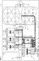
- a battery management system 1 which is used to control the connection and disconnection of consumer groups VG1, VG2, VG3, VGn to a system battery 12, for example a 110 V gel lead battery, and also to control charging of the system battery 12 via a battery charger 16 .
- the battery management system 1 has a central control device 11, which includes a processor 112 and for controlling a battery circuit breaker 10 for connecting the system battery 12 to a busbar arrangement 14 and also for controlling switching devices 171-174 for connecting and disconnecting the consumer groups VG1-VGn on the Busbar assembly 14 is used.
- the control device 11 is connected to a ballast 13 and is also connected to the battery charger 16 (with a rated output of 25 kW, for example) and an energy storage arrangement 15 in the form of a capacitor arrangement, which is used to provide energy when the system battery 12 is in a deep discharge state .
- the control device 11 has a battery current detection 111.1 for detecting a battery current on a current path 101 of the system battery 12 via a battery current sensor 100, a detection device 111.2 for detecting the block voltage via block voltage taps 122 on the system battery 12 and a detection device 111.3 for detecting a system current via a system current sensor 140 on a conductor rail of the conductor rail arrangement 14, which are each connected to the processor 112 and transmit measured values to the processor 112 for evaluation.
- An operating temperature at the system battery 12, measured via a battery temperature sensor 121 can also be recorded via the recording device 111.2 and fed to the processor 112.
- the control device 11 also has a bus driver 114 for connection to a bus system 2 via a bus connection 117 .
- a bus driver 114 for connection to a bus system 2 via a bus connection 117 .
- a wireless interface 118 for example in the form of an RFID interface
- a wireless connection 3 to an external communication device, for example using the near field communication technology.
- the control device 11 can receive control signals from an external control system 4, for example a higher-level system of a rail vehicle, via a control input 113 in order to switch on or off consumer groups VG1-VGn, for example, depending on such control signals.
- the control device 11 also has a switching assembly 115, via which a switching current can be output to the battery circuit breaker 10 and the switching devices 171-174 in order to switch the battery circuit breaker 10 or the switching devices 171-174 between different switching states, in particular to switch the system battery 12 or to connect one of the consumer groups VG1-VGn to the busbar arrangement 14 or to separate it from the busbar arrangement 14.
- the ballast 13 is used to generate a switching current that is required to switch the battery circuit breaker 10 and the switching devices 171-174.
- the ballast 13 has a setpoint adjuster 131 which is designed to control an activation circuit 132 and a power stage 133 for generating a switching current based on the setpoint as a function of a setpoint specified by the control device 11 .
- the ballast 13 delivers the switching current generated in this way to the control device 11, which feeds the switching current via the switching assembly 115, formed by a binary switch arrangement, to the battery protection switch 10 or one of the switching devices 171-174 and thus switches it between different switching states.
- the battery management system 1 can manage with a single ballast 13 .
- the ballast 13 is designed here to set the switching current according to the requirements of the assembly to be switched, depending on a setpoint value specified via the control device 11, so that the switching current has a current strength that is sufficient for switching the battery circuit breaker 10 or the switching device 171-174 to be switched is required.
- the control device 11 gives the ballast 13 a setpoint value for the switching current, which corresponds to the required switching current for the battery circuit breaker 10 and which, for example, depends on the number of pulling magnets in the battery circuit breaker 10 for mechanically adjusting the switches of the battery circuit breaker 10 depends. If, on the other hand, one of the switching devices 171-174, which are assigned to the consumer groups VG1-VGn, is to be switched, a setpoint value is specified via the control device 11 and a switching current is generated by the ballast 13 based on the setpoint value, which corresponds to that required for the switching device 171-174 switching current corresponds.
- the battery protection switch 10 - for example of the type SBG-437-02-V0171 and designed for a nominal current of 240 V, for example - is, in the illustrated embodiment, designed as a two-pole switch for switching a positive current path 101 and a negative current path 102 of the system battery 12 is used, so that both of the system battery 12 associated current paths 101, 102 can be separated from the busbar assembly 14 via the battery circuit breaker 10.
- the battery circuit breaker 10 has, for example, two pull magnets for mechanically switching the mechanical switches assigned to the individual current paths 101, 102, which must be supplied with a correspondingly high switching current in order to switch the battery circuit breaker 10 between an on state and an off state.
- the switching devices 171-174 each have, for example, only one pulling magnet and require a correspondingly smaller switching current.
- Both the battery protection switch 10 and the switching devices 171-174 are preferably each designed as a bistable switch with two stable switching states.
- the battery protection switch 10 and the switching devices 171-174 can each be switched over between the stable switching states.
- the battery circuit breaker 10 and the switching device 171-174 can, for example, each have a set coil (“S”) for setting the respective pull magnet arrangement to switch on the battery circuit breaker 10 or the switching device 171-174 and a reset coil (“R”) to reset the pull magnet arrangement to switch it off of the battery circuit breaker 10 or the switching device 171-174.
- S set coil
- R reset coil
- the consumer groups VG1-VGn can correspond to consumers of different comfort levels, for example.
- a first consumer group VG1 designed, for example, for a current of 40 A—can be assigned consumers for providing basic functions, for example emergency lighting and a door control function or the like.
- a second consumer group VG2 designed, for example, for a current of 80 A—can, in contrast, be assigned functions of a medium comfort level, for example a heating function and full lighting of a rail vehicle.
- a third load group VG3 designed, for example, for a current of 100 A—can be assigned functions of a higher comfort level, for example an air conditioning system or an inverter system for laptop sockets or the like.
- Further consumer groups VGn can be present, in which case the battery management system 1 can in principle be operated with any number of switching devices 171-174 for connecting and disconnecting different consumer groups VG1-VGn.
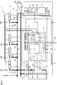
- the battery management system 1 can be integrated in a compact design in a housing 19, as is shown in an exemplary physical layout in FIG 2 is shown.
- the battery circuit breaker 10, the control device 11, the ballast 13, the switching devices 171-173, the energy storage arrangement 15 and the battery charger 16 can be integrated into such a common housing 19, with the unitary assembly created in this way preferably being in the immediate vicinity, in particular of the System battery 12 is arranged.
- connection and the disconnection of the consumer groups VG1-VGn preferably take place in a staggered manner, controlled by the control device 2.
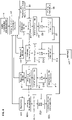
- a flow chart for switching on consumer groups VG1-VGn is to be based on the following 3 be explained.
- step A1 The connection of consumer groups VG1-VGn is triggered, for example, by a control command for so-called upgrading (step A1), which is effected, for example, by a train driver of the rail vehicle and is fed to the control device 11 via the external control system 4 .
- the consumer groups VG1-VGn are initially switched off via the switching devices 171-174, and the battery protection switch 10 is also in its off state (state A2).
- the battery condition is first checked, for example based on the battery temperature (step A3), and then it is checked whether the system battery 12 has sufficient power to connect the consumer groups VG1-VGn (step A4).
- the feed capability is evaluated, for example, by comparing the existing battery voltage U B with a threshold value Umin. If the battery voltage U B is above the threshold value Umin, it is assumed that the system battery 12 has sufficient feeding capacity. It is also assumed that there is sufficient feeding capacity when the battery charger 16 is switched on and the system battery 12 is thus being charged.
- the control device 11 sends a setpoint value for the switching current for switching the battery circuit breaker 10 to the setpoint adjuster 131 of the ballast 3.
- the switching assembly 115 is in the form the binary switch of the control device 11 is activated, and a control command for providing the switching current is sent to the power stage 133 of the ballast 13 (step A5), so that the switching current via the Switching assembly 115 is fed to the battery circuit breaker 10 and accordingly the battery circuit breaker 10 is switched from its off state to the on state (step A6).
- the switching assembly 115 is switched off again and the switching current is therefore no longer passed through to the battery protection switch 10 .
- This predetermined time t v is measured in such a way that the battery protection switch 10 is switched reliably, but is not overloaded.
- step A7 the control device 11 determines a new target value for switching the switching device 171 and sends it to the ballast 13 .
- the switching assembly 115 in the form of the binary switch is switched on via a control command DIGOUT 02, an ON command is sent to the power stage 133 of the ballast 13 and the switching current set by the setpoint adjuster 131 on the basis of the setpoint is thus routed to the switching device 171 (step A7), which thus switches and the consumer group VG1 switches on (step A8).
- step A7 the control command DIGOUT 02 and thus the switching current is switched off.
- step A9 the setpoint for switching the switching device 172 is determined by the control device 11 and sent to the setpoint adjuster 131 of the ballast 13, the switching assembly 115 in the form of the binary switch is switched on with a control command DIGOUT 03 and the power stage 133 of the Ballast 13 driven to generate the switching current.
- the switching device 172 is thus switched on and the load module VG2 is switched on (step A10). After a predetermined time tv, the control command DIGOUT 03 and thus the switching current are switched off again.
- the control device 11 enters a Setpoint for switching the switching device 173 is generated and sent to the setpoint adjuster 131 of the ballast 13, the switching assembly 115 is switched on by means of a control command DIGOUT 04 and the power stage 133 of the ballast 13 is controlled to generate the switching current based on the set setpoint (step A11).
- the switching device 173 is thus switched on and thus the consumer group VG3 is switched on (step A12), and after a predetermined time t v the switching assembly 115 and thus the switching current are switched off again.
- step A13 If further consumer groups VGn are present, further switching devices 174 can be switched in the same way (step A13).
- step A14 If the desired consumer groups VG1-VGn are switched on, a check is carried out continuously or at predetermined time intervals during normal operation to determine whether the system battery 12 has sufficient feed capacity (step A14). If so, normal operation continues. However, if this is not the case (step A15), a shutdown procedure may be initiated, within which the consumer groups VG1-VGn are switched off again (steps A16 and A17).
- the switching current can be limited via an inrush current limiter in such a way that a thermal or magnetic safety function of the battery circuit breaker 10 or the respective switching device 171-174 is not triggered and the battery circuit breaker 10 and the switching devices 171-174 are thus switched reliably.
- the switching on of the consumer groups VG1-VGn thus takes place in a time-staggered manner, in that the battery protection switch 10 and the switching devices 171-174 are activated one after the other. In this case, the switching on takes place with repeated monitoring of the feed capacity of the system battery 12 based on the existing battery voltage U B .
- FIG. 4 shows a flow chart for switching off consumer groups VG1-VGn in a time-staggered manner.
- the dismantling i.e. the switching off of the consumer groups VG1-VGn, is carried out, for example, by a dismantling command, for example a corresponding control command from a train driver, which is sent to the control device 11 via the external control system 4, or when insufficient supply capacity is detected at the system battery 12 (step A14 in 3 ) triggered (step B1 in 4 ). If there is a criterion for dismantling, the consumer groups VG1-VGn are switched off one after the other, starting with the highest comfort level (consumer group VGn) (with the exception of an emergency shutdown, in which the shutdown takes place simultaneously (step B25)).
- a dismantling command for example a corresponding control command from a train driver
- step B2 it is first checked whether the system battery 12 has reached a certain depth of discharge. This is done in particular by checking whether the battery voltage U B has fallen below a predetermined threshold value Umin.
- the dismantling can generally take place in a staggered manner with predetermined time intervals t v1 -t v3 and t vBSS specified on the basis of the consumer groups VG1-VGn. For example, it may be necessary for a consumer group VG1-VGn to be supplied with power for a certain amount of time, for example a few minutes or even a few hours, when a shutdown command is present, in order to carry out certain functions.
- step B2 If it is determined in step B2 that the system battery 12 does not have sufficient charging capacity because the battery voltage U B is less than the threshold value Umin, the consumer groups VG1-VG N can also be switched off without a time delay, i.e. without complying with the predetermined times t v1 -t v3 and t vBSS are done.
- steps B3 to B7 the consumer group VG3 (assuming that no other consumer groups VGn are present) are switched off by after a predetermined, assigned time t v1 (step B3, unless it has been determined in step B2 that the battery voltage U B is smaller than the threshold value Umin), a switching current for resetting the switching device 173 is generated via the ballast 13 (step B4) and via the switching assembly 115 of the switching device 173 is supplied (step S5), so that the consumer group VG3 is switched off (step B6).
- the correct shutdown is checked in step B7.
- steps B10 to B14 for consumer group VG2 This is repeated in steps B10 to B14 for consumer group VG2, in steps B15 to B19 for consumer group VG1 and in steps B20 to B24 for battery circuit breaker 10, with the respective delay time t v2 , t v3 , t vBSS each with checking the switching off of the previous consumer group begins and is complied with, unless it is determined during repeated testing in step B2 that the battery voltage U B is less than the threshold value Umin.
- the predetermined times t v1 -t v3 and t vBSS can be the same or different.
- the threshold value Umin for checking the depth of discharge for the individual consumer groups VG1-VGn can be the same or different.
- a warning in the form of a message to the higher-level control system 4 can be generated for the train driver (step B9).
- step B25 the shutdown can also take place simultaneously, so that all switching devices 171-174 and the battery circuit breaker 10 are switched simultaneously to separate the consumer groups VG1-VGn from the system battery 12.
- the system battery 12 can become totally discharged or there can be voltage differences between assemblies (e.g. if the rail vehicle is idle for a long time without being fed in).
- the control device 11 of the battery management system 1 is designed to detect such states and initiates an equalizing charge via the battery charger 16 when a deep discharge state is detected.
- Such an equalizing charge requires a charging current with a comparatively low current intensity, referred to as I20, corresponding to a twentieth of the nominal current over a defined period of time, for example a period between 44 hours and 48 hours, in order to achieve effective charging of the system battery 12 .
- a separate converter for feeding the output charge into the system battery 12 can be dispensed with here.
- the battery charger 16 has a control input 161 which enables the output voltage of the battery charger 16 to be adjusted via an analog output 116 of the control device 11 .
- the battery charger 16 is controlled here via the switching assembly 115 in the form of the binary switch of the control device 11, which is connected to a digital input 162 of the battery charger 16, in that the switching assembly 115 sends a switching command for the equalizing charge to the battery charger 16.
- measured values from the battery current sensor 100, the battery temperature sensor 121 and the block voltage obtained via the block voltage taps 122 can also be taken into account.
- the equalizing charging process is controlled via the control device 11, which regulates the battery charger 16 during the equalizing charging process and also sends a message to a train driver, for example, via the data bus system 2, by means of which the train driver is asked, for example, to connect the rail vehicle to an external power supply for feeding in external energy becomes.
- the system voltage is generally regulated via the battery charger 16.
- the additional energy storage arrangement 15 in the form of a capacitor assembly, for example using so-called supercapacitors, is used in the event of an extreme deep discharge of the system battery 12, which may also damage the system battery 12, to carry out an emergency start regime.
- the energy storage arrangement 15 is connected to the busbar arrangement 14 under the control of the control device 11 and energy is thus fed into the system from capacitors 155 of the energy storage arrangement 15 . Feeding in takes place via a feedback thyristor 153 and an inrush current limiter 152 and is controlled via a control unit 151.
- the control device 11 is in particular connected to a switch 154 of the energy storage arrangement 15, which is connected to the busbar arrangement 14 in order to connect the energy storage arrangement 15.
- the energy storage arrangement 15 can, for example, make so much energy available that certain emergency functions can be carried out.
- the battery charger 16 can be started with the energy storage arrangement 5 in order to initiate an equalization charging process for the system battery 12 .
- the bus connection 117 for connecting to the bus system 2 of a vehicle control level can be compatible with an iCOM system, for example. Control commands can be received via bus connection 117. In addition, a system configuration is possible.
- Diagnostic data can be read out, for example, via the wireless interface 118, designed, for example, by an RFID interface.
- a user can connect to the control device 11 via the data interface 118, for example using a communication device in the form of a smartphone or the like, in order to read diagnostic data for maintenance or repairs.
- the control device 11 can record and evaluate measured values from different sensors, in particular from the battery current sensor 100, the system current sensor 140, the battery temperature sensor 121 and the block voltage To create service life forecasts of the system battery 12 and other assemblies, in particular the battery circuit breaker 10 and the switching devices 171-174.
- the control device 11 can record operating data of the battery charger 16, which enables the MTBF (Mean Time Between Failures) to be calculated in order to verify values predicted in the so-called RPA (Reliability Prediction Analysis).
- U BB is the block voltage
- ⁇ Elyt the electrolyte temperature
- n Zyc the number of cycles
- E N the nominal energy throughput (battery-specific value)
- f l the multiple of the discharge current
- ta the average operating temperature.
- the calculation is carried out at specific time intervals, with linear interpolation between sets of characteristic curves. With each recalculation, the accuracy of the service life prediction is (quasi-) iteratively improved by the cumulative cycle evaluation.
- a predetermined service life limit is reached, an error message is sent to the vehicle control system via the bus system 2 . A pre-warning signal is sent even before the service life limit is reached, so that appropriate preventive measures can be initiated.
- a service life prognosis for the battery circuit breaker 10 and the switching devices 171-174 can also be created.
- the respective switching current of the battery protection switch 10 or of the respective switching devices 171-174 is evaluated by the control device 11 at the switching moment, which enables a service life prognosis for each of these switches.
- figure 5 shows a typical characteristic for the battery circuit breaker 10 and the switching device 171-174. The is shown in a double-logarithmic manner Service life, indicated by the number of switching cycles, depending on the switching current. Such characteristic curves can be determined, for example, by series of measurements in long-term tests.
- a service life prognosis for the battery circuit breaker 10 and the switching devices 171-174, measured values for the switching current during switching are recorded by the control device 11, so that a service life prognosis can be calculated by counting switching cycles (n cyc ) with a corresponding switching current evaluation. For example, an average switching current over the total number of switching cycles can be determined on the basis of the detected switching current, in order then to determine an estimated service life, ie a total possible number of switching cycles, on the basis of the characteristic curve. In this case, too, when the end of service life is reached, an error message is generated and sent to the vehicle control system via the bus system 2 .
- the current service life prognosis data can be called up at any time via the (RFID) interface 118 and are therefore available to the operator for preventive maintenance planning.
Claims (15)
- Système de gestion de batterie (1), notamment pour un véhicule ferroviaire, comprenant une batterie d'équipement (12), un arrangement de barres-bus (14), un disjoncteur de batterie (10) servant à la connexion commutable de la batterie d'équipement (12) à l'arrangement de barres-bus (14) et au moins un dispositif de commutation (171-174) servant à la connexion commutable d'au moins un groupe de récepteurs (VG1-VGn) à l'arrangement de barres-bus (14),
caractérisé parun dispositif de commande (11) destiné à commander des opérations de commutation pour commuter le disjoncteur de batterie (10) et l'au moins un dispositif de commutation (171-174) et un régulateur de puissance (13) unique destiné à générer un courant de commutation servant à la commutation du disjoncteur de batterie (10) et de l'au moins un dispositif de commutation (171-174), le dispositif de commande (11) étant configuré pour fournir au régulateur de puissance (13) une valeur de consigne pour le courant de commutation servant à la commutation du disjoncteur de batterie (10) ou de l'au moins un dispositif de commutation (171-174),le dispositif de commande (11) étant configuré pour transmettre une première valeur de consigne pour un courant de commutation servant à la commutation du disjoncteur de batterie (10) et une deuxième valeur de consigne pour un courant de commutation servant à la commutation de l'au moins un dispositif de commutation (171-174),le régulateur de puissance (13) possédant un élément de réglage de valeur de consigne (131) destiné à régler le courant de commutation en fonction de la valeur de consigne reçue par le dispositif de commande (11) etle dispositif de commande (11) étant configuré pour commander plusieurs éléments de commutation (115), lesquels effectuent la distribution des courants de commutation délivrés par le régulateur de puissance (13), adaptés au dispositif de commutation (171-174) respectif, sur les dispositifs de commutation (171-174) à commander. - Système de gestion de batterie (1) selon la revendication 1, caractérisé en ce que le régulateur de puissance (13) possède un étage de puissance (133) destiné à générer le courant de commutation servant à la commutation du disjoncteur de batterie (10) et de l'au moins un dispositif de commutation (171-174).
- Système de gestion de batterie (1) selon l'une des revendications précédentes, caractérisé en ce que le dispositif de commande (11), le régulateur de puissance (13), le disjoncteur de batterie (10) et l'au moins un dispositif de commutation (171-174) sont disposés dans un boîtier (19) commun.
- Système de gestion de batterie (1) selon l'une des revendications précédentes, caractérisé en ce que le dispositif de commande (11) est configuré pour déclencher une opération de commutation destinée à la commutation du disjoncteur de batterie (10) ou de l'au moins un dispositif de commutation (171-174) en fonction d'un état de charge de la batterie d'équipement (12).
- Système de gestion de batterie (1) selon l'une des revendications précédentes, caractérisé par un capteur de courant de batterie (100) destiné à mesurer un flux de courant entre la batterie d'équipement (12) et l'arrangement de barres-bus (14).
- Système de gestion de batterie (1) selon la revendication 5, caractérisé en ce que le dispositif de commande (11) est configuré pour interpréter les opérations de commutation du disjoncteur de batterie (10) et/ou de l'au moins un dispositif de commutation (171-174) à l'aide de valeurs mesurées du capteur de courant de batterie (100) associées aux opérations de commutation en vue de déterminer une valeur caractéristique indicative de la durée de vie du disjoncteur de batterie (10) et/ou de l'au moins un dispositif de commutation (171-174).
- Système de gestion de batterie (1) selon la revendication 6, caractérisé en ce que le dispositif de commande (11) est configuré pour, en plus des valeurs mesurées du capteur de courant de batterie (100), interpréter les valeurs mesurées d'un capteur de courant d'équipement (140), lequel est disposé pour mesurer un flux de courant sur l'arrangement de barres-bus (14), en vue de déterminer la valeur caractéristique indicative de la durée de vie du disjoncteur de batterie (10) et/ou de l'au moins un dispositif de commutation (171-174).
- Système de gestion de batterie (1) selon l'une des revendications précédentes, caractérisé en ce que le disjoncteur de batterie (10) est de configuration bipolaire pour la commutation de deux trajets de courant (101, 102), par le biais desquels la batterie d'équipement (12) peut être connectée à l'arrangement de barres-bus (14).
- Système de gestion de batterie (1) selon l'une des revendications précédentes, caractérisé en ce que le disjoncteur de batterie (10) possède deux états de commutation stables.
- Système de gestion de batterie (1) selon l'une des revendications précédentes, caractérisé en ce que l'au moins un dispositif de commutation (171-174) est de configuration unipolaire pour la commutation d'un trajet de courant (175-178), par le biais duquel l'au moins un groupe de récepteurs (VG1-VGn) peut être connecté à l'arrangement de barres-bus (14).
- Système de gestion de batterie (1) selon l'une des revendications précédentes, caractérisé en ce que l'au moins un dispositif de commutation (171-174) possède deux états de commutation stables.
- Système de gestion de batterie (1) selon l'une des revendications précédentes, caractérisé en ce que le disjoncteur de batterie (10) et/ou l'au moins un dispositif de commutation (171-174) possèdent une fonction de sécurité thermique et/ou magnétique.
- Système de gestion de batterie (1) selon l'une des revendications précédentes, caractérisé par un chargeur de batterie (16) connecté à l'arrangement de barres-bus (14) et destiné à charger la batterie d'équipement (12), le dispositif de commande (11) étant configuré pour commander le chargeur de batterie (16) en fonction de l'état de charge de la batterie d'équipement (12).
- Système de gestion de batterie (1) selon l'une des revendications précédentes, caractérisé par un arrangement d'accumulation d'énergie (15) supplémentaire, connecté à l'arrangement de barres-bus (14), destiné à fournir de l'énergie électrique dans un état de décharge profonde de la batterie d'équipement (12), le dispositif de commande (11) étant configuré pour commander l'arrangement d'accumulation d'énergie (15).
- Système de gestion de batterie (1) selon l'une des revendications précédentes, caractérisé en ce que le système de gestion de batterie (1) possède une pluralité de dispositifs de commutation (171-174) servant à la connexion commutable d'une pluralité de groupes de récepteurs (VG1-VGn) à l'arrangement de barres-bus (14).
Applications Claiming Priority (2)
| Application Number | Priority Date | Filing Date | Title |
|---|---|---|---|
| DE102018109594.5A DE102018109594A1 (de) | 2018-04-20 | 2018-04-20 | Batteriemanagementsystem, insbesondere für ein Schienenfahrzeug |
| PCT/EP2019/059990 WO2019202030A1 (fr) | 2018-04-20 | 2019-04-17 | Système de gestion de batterie muni d'une commande de commutateurs, en particulier pour un véhicule ferroviaire |
Publications (2)
| Publication Number | Publication Date |
|---|---|
| EP3781430A1 EP3781430A1 (fr) | 2021-02-24 |
| EP3781430B1 true EP3781430B1 (fr) | 2022-12-14 |
Family
ID=66379879
Family Applications (1)
| Application Number | Title | Priority Date | Filing Date |
|---|---|---|---|
| EP19721221.0A Active EP3781430B1 (fr) | 2018-04-20 | 2019-04-17 | Système de gestion de batterie muni d'une commande de commutateurs, en particulier pour un véhicule ferroviaire |
Country Status (6)
| Country | Link |
|---|---|
| EP (1) | EP3781430B1 (fr) |
| CN (1) | CN112533787A (fr) |
| DE (1) | DE102018109594A1 (fr) |
| ES (1) | ES2939724T3 (fr) |
| PT (1) | PT3781430T (fr) |
| WO (1) | WO2019202030A1 (fr) |
Families Citing this family (4)
| Publication number | Priority date | Publication date | Assignee | Title |
|---|---|---|---|---|
| CN112864479B (zh) * | 2019-11-12 | 2022-06-07 | 株洲中车时代电气股份有限公司 | 一种轨道交通锂电池管理系统及电池系统 |
| DE102020131819A1 (de) | 2020-12-01 | 2022-06-02 | PTC Rail Services GmbH | Schaltungsanordnung und Verfahren zum energieoptimierten Betrieb elektromagnetischer Triebsysteme |
| CN113991263B (zh) * | 2021-10-09 | 2023-06-02 | 广东汇天航空航天科技有限公司 | 动力系统以及可飞行装置 |
| CN113922451A (zh) * | 2021-10-13 | 2022-01-11 | 南京汉瑞交通技术有限公司 | 一种适用于轨道交通的备用电源系统 |
Citations (1)
| Publication number | Priority date | Publication date | Assignee | Title |
|---|---|---|---|---|
| DE202011051972U1 (de) * | 2011-11-15 | 2012-01-23 | Pcs Power Converter Solutions Gmbh | Schaltungsanordnung zum Ansteuern eines Schaltgerätes |
Family Cites Families (8)
| Publication number | Priority date | Publication date | Assignee | Title |
|---|---|---|---|---|
| DE3822021C1 (fr) | 1988-06-30 | 1989-10-19 | Auergesellschaft Gmbh, 1000 Berlin, De | |
| DE10026835B4 (de) | 2000-05-30 | 2004-12-30 | Fahrzeugausrüstung Berlin GmbH | Schaltungsanordnung und Verfahren zur Vermeidung von Tiefenladezuständen bei Bleibatterien in batteriegepufferten elektrischen Anlagen, insbesondere in Schienenfahrzeugen |
| EP2428387A4 (fr) * | 2009-04-23 | 2017-03-22 | Toyota Jidosha Kabushiki Kaisha | Système d'alimentation électrique de véhicule électrique et procédé de commande correspondant |
| KR101217074B1 (ko) * | 2011-02-21 | 2012-12-31 | 로베르트 보쉬 게엠베하 | 배터리 관리 시스템 |
| JP5865013B2 (ja) * | 2011-10-27 | 2016-02-17 | 三洋電機株式会社 | 車両用の電源装置及びこの電源装置を備える車両 |
| DE102012214554A1 (de) * | 2012-08-16 | 2014-02-20 | Robert Bosch Gmbh | Verfahren zur Überführung von Batterien in einen entladenen Zustand, Batteriemanagementsystem, Inverter, System zur Erzeugung einer Wechselspannung, Ladestromquelle und Kraftfahrzeug |
| DE102014220033A1 (de) * | 2014-10-02 | 2016-04-07 | Robert Bosch Gmbh | Elektrochemische Energiespeichereinrichtung für eine Speichereinheit eines Systems zur elektrochemischen Energiespeicherung, Verfahren zum Steuern eines Flusses elektrischer Energie in einem System zur elektrochemischen Energiespeicherung und System zur elektrochemischen Energiespeicherung |
| DE102015015580A1 (de) | 2015-12-04 | 2017-06-08 | Pcs Power Converter Solutions Gmbh | Schaltungsanordnung zum Betrieb elektromagnetischer Triebsysteme |
-
2018
- 2018-04-20 DE DE102018109594.5A patent/DE102018109594A1/de active Pending
-
2019
- 2019-04-17 ES ES19721221T patent/ES2939724T3/es active Active
- 2019-04-17 WO PCT/EP2019/059990 patent/WO2019202030A1/fr active Application Filing
- 2019-04-17 EP EP19721221.0A patent/EP3781430B1/fr active Active
- 2019-04-17 CN CN201980027134.3A patent/CN112533787A/zh active Pending
- 2019-04-17 PT PT197212210T patent/PT3781430T/pt unknown
Patent Citations (1)
| Publication number | Priority date | Publication date | Assignee | Title |
|---|---|---|---|---|
| DE202011051972U1 (de) * | 2011-11-15 | 2012-01-23 | Pcs Power Converter Solutions Gmbh | Schaltungsanordnung zum Ansteuern eines Schaltgerätes |
Also Published As
| Publication number | Publication date |
|---|---|
| PT3781430T (pt) | 2023-03-20 |
| WO2019202030A1 (fr) | 2019-10-24 |
| ES2939724T3 (es) | 2023-04-26 |
| CN112533787A (zh) | 2021-03-19 |
| EP3781430A1 (fr) | 2021-02-24 |
| DE102018109594A1 (de) | 2019-10-24 |
Similar Documents
| Publication | Publication Date | Title |
|---|---|---|
| EP3781430B1 (fr) | Système de gestion de batterie muni d'une commande de commutateurs, en particulier pour un véhicule ferroviaire | |
| EP3390133B1 (fr) | Module de sécurité et station de charge munie d'un module de sécurité | |
| EP0582913B1 (fr) | Dispositif de commutation | |
| DE112018005101T5 (de) | Konfigurierbares batteriepack zum schnellladen | |
| DE102017103730A1 (de) | Schaltung und Verfahren zur Detektion von Batteriezellverschlechterungsereignissen | |
| DE112013003194T5 (de) | Batteriesatz-Wartungsvorrichtung für Hybrid- und Elektrofahrzeuge | |
| DE102018106489A1 (de) | Duale bus-batterie-vorladeschaltung | |
| EP2435279B1 (fr) | Réseau de bord pour un véhicule ainsi que dispositif de commande pour un réseau de bord | |
| EP2630000A2 (fr) | Système de gestion de batterie pour système d'alimentation électrique comprenant une zone basse tension et une zone haute tension | |
| DE112010006053T5 (de) | Ladevorrichtung und Verfahren zum Steuern einer Ladevorrichtung | |
| WO2012163504A2 (fr) | Dispositif et procédé pour décharger automatiquement une batterie de véhicule | |
| DE102012222208A1 (de) | Verfahren zum gesteuerten Verbinden mehrerer Bordnetzzweige eines Fahrzeugs, Steuereinheit zur Ausführung des Verfahrens sowie Bordnetz | |
| DE102014202504A1 (de) | Trenneinheit zur galvanischen Trennung des Leistungsstromkreises zwischen einer Spannungsquelle und einer Verbrauchereinrichtung sowie Batteriesystem mit einer solchen Trenneinheit | |
| EP3342629B1 (fr) | Technique de connexion variable d'un système d'accumulation d'énergie de traction | |
| WO2019034474A1 (fr) | Dispositif d'interruption pour un réseau d'alimentation électrique | |
| DE112014007109T5 (de) | Fahrzeuggleichspannungswandler | |
| DE102017103375A1 (de) | Fehlererkennung in einem mehrfach-hochspannungsbussystem | |
| EP2786891A1 (fr) | Système de batterie, véhicule avec système de batterie et procédé de fonctionnement d'un système de batterie dans un véhicule | |
| DE102016109074A1 (de) | Verfahren und Anordnung zum Laden einer Fahrzeugbatterie | |
| DE102013225732A1 (de) | Hochvolt-Sicherung für Fahrzeuge | |
| EP3273507B1 (fr) | Système accumulateur d'énergie de traction pour véhicule | |
| EP1468863B1 (fr) | Dispositif et procédé de contrôle d'une batterie éléctrique dans un submersible | |
| WO2015150131A1 (fr) | Procédé de surveillance de l'état des contacts d'un contacteur commandable au moyen d'une bobine excitatrice | |
| EP3698419A1 (fr) | Système de batterie haute tension et procédé de fonctionnement d'un système de batterie haute tension | |
| DE102015014181A1 (de) | Hochvolt-Netz für ein Kraftfahrzeug und Verfahren zum Betreiben eines Hochvolt-Netzes |
Legal Events
| Date | Code | Title | Description |
|---|---|---|---|
| STAA | Information on the status of an ep patent application or granted ep patent |
Free format text: STATUS: UNKNOWN |
|
| STAA | Information on the status of an ep patent application or granted ep patent |
Free format text: STATUS: THE INTERNATIONAL PUBLICATION HAS BEEN MADE |
|
| PUAI | Public reference made under article 153(3) epc to a published international application that has entered the european phase |
Free format text: ORIGINAL CODE: 0009012 |
|
| STAA | Information on the status of an ep patent application or granted ep patent |
Free format text: STATUS: REQUEST FOR EXAMINATION WAS MADE |
|
| 17P | Request for examination filed |
Effective date: 20201119 |
|
| AK | Designated contracting states |
Kind code of ref document: A1 Designated state(s): AL AT BE BG CH CY CZ DE DK EE ES FI FR GB GR HR HU IE IS IT LI LT LU LV MC MK MT NL NO PL PT RO RS SE SI SK SM TR |
|
| AX | Request for extension of the european patent |
Extension state: BA ME |
|
| DAV | Request for validation of the european patent (deleted) | ||
| DAX | Request for extension of the european patent (deleted) | ||
| GRAP | Despatch of communication of intention to grant a patent |
Free format text: ORIGINAL CODE: EPIDOSNIGR1 |
|
| STAA | Information on the status of an ep patent application or granted ep patent |
Free format text: STATUS: GRANT OF PATENT IS INTENDED |
|
| INTG | Intention to grant announced |
Effective date: 20220628 |
|
| GRAS | Grant fee paid |
Free format text: ORIGINAL CODE: EPIDOSNIGR3 |
|
| GRAA | (expected) grant |
Free format text: ORIGINAL CODE: 0009210 |
|
| STAA | Information on the status of an ep patent application or granted ep patent |
Free format text: STATUS: THE PATENT HAS BEEN GRANTED |
|
| AK | Designated contracting states |
Kind code of ref document: B1 Designated state(s): AL AT BE BG CH CY CZ DE DK EE ES FI FR GB GR HR HU IE IS IT LI LT LU LV MC MK MT NL NO PL PT RO RS SE SI SK SM TR |
|
| REG | Reference to a national code |
Ref country code: GB Ref legal event code: FG4D Free format text: NOT ENGLISH |
|
| REG | Reference to a national code |
Ref country code: CH Ref legal event code: EP |
|
| REG | Reference to a national code |
Ref country code: DE Ref legal event code: R096 Ref document number: 502019006530 Country of ref document: DE |
|
| RAP4 | Party data changed (patent owner data changed or rights of a patent transferred) |
Owner name: ELLENBERGER & POENSGEN GMBH Owner name: POWERTECH CONVERTER GMBH |
|
| REG | Reference to a national code |
Ref country code: IE Ref legal event code: FG4D Free format text: LANGUAGE OF EP DOCUMENT: GERMAN |
|
| REG | Reference to a national code |
Ref country code: AT Ref legal event code: REF Ref document number: 1537479 Country of ref document: AT Kind code of ref document: T Effective date: 20230115 |
|
| REG | Reference to a national code |
Ref country code: PT Ref legal event code: SC4A Ref document number: 3781430 Country of ref document: PT Date of ref document: 20230320 Kind code of ref document: T Free format text: AVAILABILITY OF NATIONAL TRANSLATION Effective date: 20230314 |
|
| REG | Reference to a national code |
Ref country code: NL Ref legal event code: FP |
|
| REG | Reference to a national code |
Ref country code: LT Ref legal event code: MG9D |
|
| REG | Reference to a national code |
Ref country code: ES Ref legal event code: FG2A Ref document number: 2939724 Country of ref document: ES Kind code of ref document: T3 Effective date: 20230426 |
|
| PG25 | Lapsed in a contracting state [announced via postgrant information from national office to epo] |
Ref country code: SE Free format text: LAPSE BECAUSE OF FAILURE TO SUBMIT A TRANSLATION OF THE DESCRIPTION OR TO PAY THE FEE WITHIN THE PRESCRIBED TIME-LIMIT Effective date: 20221214 Ref country code: LT Free format text: LAPSE BECAUSE OF FAILURE TO SUBMIT A TRANSLATION OF THE DESCRIPTION OR TO PAY THE FEE WITHIN THE PRESCRIBED TIME-LIMIT Effective date: 20221214 Ref country code: FI Free format text: LAPSE BECAUSE OF FAILURE TO SUBMIT A TRANSLATION OF THE DESCRIPTION OR TO PAY THE FEE WITHIN THE PRESCRIBED TIME-LIMIT Effective date: 20221214 |
|
| REG | Reference to a national code |
Ref country code: NO Ref legal event code: T2 Effective date: 20221214 |
|
| PG25 | Lapsed in a contracting state [announced via postgrant information from national office to epo] |
Ref country code: RS Free format text: LAPSE BECAUSE OF FAILURE TO SUBMIT A TRANSLATION OF THE DESCRIPTION OR TO PAY THE FEE WITHIN THE PRESCRIBED TIME-LIMIT Effective date: 20221214 Ref country code: LV Free format text: LAPSE BECAUSE OF FAILURE TO SUBMIT A TRANSLATION OF THE DESCRIPTION OR TO PAY THE FEE WITHIN THE PRESCRIBED TIME-LIMIT Effective date: 20221214 Ref country code: HR Free format text: LAPSE BECAUSE OF FAILURE TO SUBMIT A TRANSLATION OF THE DESCRIPTION OR TO PAY THE FEE WITHIN THE PRESCRIBED TIME-LIMIT Effective date: 20221214 Ref country code: GR Free format text: LAPSE BECAUSE OF FAILURE TO SUBMIT A TRANSLATION OF THE DESCRIPTION OR TO PAY THE FEE WITHIN THE PRESCRIBED TIME-LIMIT Effective date: 20230315 |
|
| PGFP | Annual fee paid to national office [announced via postgrant information from national office to epo] |
Ref country code: TR Payment date: 20230307 Year of fee payment: 5 |
|
| PGFP | Annual fee paid to national office [announced via postgrant information from national office to epo] |
Ref country code: NL Payment date: 20230417 Year of fee payment: 5 |
|
| PG25 | Lapsed in a contracting state [announced via postgrant information from national office to epo] |
Ref country code: SM Free format text: LAPSE BECAUSE OF FAILURE TO SUBMIT A TRANSLATION OF THE DESCRIPTION OR TO PAY THE FEE WITHIN THE PRESCRIBED TIME-LIMIT Effective date: 20221214 Ref country code: RO Free format text: LAPSE BECAUSE OF FAILURE TO SUBMIT A TRANSLATION OF THE DESCRIPTION OR TO PAY THE FEE WITHIN THE PRESCRIBED TIME-LIMIT Effective date: 20221214 Ref country code: EE Free format text: LAPSE BECAUSE OF FAILURE TO SUBMIT A TRANSLATION OF THE DESCRIPTION OR TO PAY THE FEE WITHIN THE PRESCRIBED TIME-LIMIT Effective date: 20221214 |
|
| PGFP | Annual fee paid to national office [announced via postgrant information from national office to epo] |
Ref country code: PT Payment date: 20230417 Year of fee payment: 5 Ref country code: NO Payment date: 20230418 Year of fee payment: 5 Ref country code: IT Payment date: 20230426 Year of fee payment: 5 Ref country code: FR Payment date: 20230417 Year of fee payment: 5 Ref country code: ES Payment date: 20230517 Year of fee payment: 5 Ref country code: DE Payment date: 20230307 Year of fee payment: 5 Ref country code: CH Payment date: 20230502 Year of fee payment: 5 |
|
| PG25 | Lapsed in a contracting state [announced via postgrant information from national office to epo] |
Ref country code: IS Free format text: LAPSE BECAUSE OF FAILURE TO SUBMIT A TRANSLATION OF THE DESCRIPTION OR TO PAY THE FEE WITHIN THE PRESCRIBED TIME-LIMIT Effective date: 20230414 Ref country code: AL Free format text: LAPSE BECAUSE OF FAILURE TO SUBMIT A TRANSLATION OF THE DESCRIPTION OR TO PAY THE FEE WITHIN THE PRESCRIBED TIME-LIMIT Effective date: 20221214 |
|
| REG | Reference to a national code |
Ref country code: DE Ref legal event code: R097 Ref document number: 502019006530 Country of ref document: DE |
|
| PLBE | No opposition filed within time limit |
Free format text: ORIGINAL CODE: 0009261 |
|
| STAA | Information on the status of an ep patent application or granted ep patent |
Free format text: STATUS: NO OPPOSITION FILED WITHIN TIME LIMIT |
|
| PG25 | Lapsed in a contracting state [announced via postgrant information from national office to epo] |
Ref country code: DK Free format text: LAPSE BECAUSE OF FAILURE TO SUBMIT A TRANSLATION OF THE DESCRIPTION OR TO PAY THE FEE WITHIN THE PRESCRIBED TIME-LIMIT Effective date: 20221214 |
|
| PGFP | Annual fee paid to national office [announced via postgrant information from national office to epo] |
Ref country code: GB Payment date: 20230420 Year of fee payment: 5 |
|
| 26N | No opposition filed |
Effective date: 20230915 |
|
| PG25 | Lapsed in a contracting state [announced via postgrant information from national office to epo] |
Ref country code: SI Free format text: LAPSE BECAUSE OF FAILURE TO SUBMIT A TRANSLATION OF THE DESCRIPTION OR TO PAY THE FEE WITHIN THE PRESCRIBED TIME-LIMIT Effective date: 20221214 |
|
| PG25 | Lapsed in a contracting state [announced via postgrant information from national office to epo] |
Ref country code: LU Free format text: LAPSE BECAUSE OF NON-PAYMENT OF DUE FEES Effective date: 20230417 |
|
| REG | Reference to a national code |
Ref country code: BE Ref legal event code: MM Effective date: 20230430 |
|
| PG25 | Lapsed in a contracting state [announced via postgrant information from national office to epo] |
Ref country code: MC Free format text: LAPSE BECAUSE OF FAILURE TO SUBMIT A TRANSLATION OF THE DESCRIPTION OR TO PAY THE FEE WITHIN THE PRESCRIBED TIME-LIMIT Effective date: 20221214 |
|
| PG25 | Lapsed in a contracting state [announced via postgrant information from national office to epo] |
Ref country code: MC Free format text: LAPSE BECAUSE OF FAILURE TO SUBMIT A TRANSLATION OF THE DESCRIPTION OR TO PAY THE FEE WITHIN THE PRESCRIBED TIME-LIMIT Effective date: 20221214 |
|
| REG | Reference to a national code |
Ref country code: IE Ref legal event code: MM4A |
|
| PG25 | Lapsed in a contracting state [announced via postgrant information from national office to epo] |
Ref country code: BE Free format text: LAPSE BECAUSE OF NON-PAYMENT OF DUE FEES Effective date: 20230430 |
|
| REG | Reference to a national code |
Ref country code: AT Ref legal event code: PC Ref document number: 1537479 Country of ref document: AT Kind code of ref document: T Owner name: ELLENBERGER & POENSGEN GMBH, DE Effective date: 20240122 Ref country code: AT Ref legal event code: PC Ref document number: 1537479 Country of ref document: AT Kind code of ref document: T Owner name: ABB SCHWEIZ AG, CH Effective date: 20240122 |
|
| REG | Reference to a national code |
Ref country code: DE Ref legal event code: R081 Ref document number: 502019006530 Country of ref document: DE Owner name: ELLENBERGER & POENSGEN GMBH, DE Free format text: FORMER OWNERS: ELLENBERGER & POENSGEN GMBH, 90518 ALTDORF, DE; POWERTECH CONVERTER GMBH, 13507 BERLIN, DE Ref country code: DE Ref legal event code: R081 Ref document number: 502019006530 Country of ref document: DE Owner name: ABB SCHWEIZ AG, CH Free format text: FORMER OWNERS: ELLENBERGER & POENSGEN GMBH, 90518 ALTDORF, DE; POWERTECH CONVERTER GMBH, 13507 BERLIN, DE |
|
| PG25 | Lapsed in a contracting state [announced via postgrant information from national office to epo] |
Ref country code: IE Free format text: LAPSE BECAUSE OF NON-PAYMENT OF DUE FEES Effective date: 20230417 |