EP3781069B1 - Systèmes chirurgicaux robotiques et leurs chariots de bras robotisés - Google Patents
Systèmes chirurgicaux robotiques et leurs chariots de bras robotisés Download PDFInfo
- Publication number
- EP3781069B1 EP3781069B1 EP19789524.6A EP19789524A EP3781069B1 EP 3781069 B1 EP3781069 B1 EP 3781069B1 EP 19789524 A EP19789524 A EP 19789524A EP 3781069 B1 EP3781069 B1 EP 3781069B1
- Authority
- EP
- European Patent Office
- Prior art keywords
- carriage
- pinion
- support column
- brake
- robotic arm
- Prior art date
- Legal status (The legal status is an assumption and is not a legal conclusion. Google has not performed a legal analysis and makes no representation as to the accuracy of the status listed.)
- Active
Links
Images


Classifications
-
- A—HUMAN NECESSITIES
- A61—MEDICAL OR VETERINARY SCIENCE; HYGIENE
- A61B—DIAGNOSIS; SURGERY; IDENTIFICATION
- A61B34/00—Computer-aided surgery; Manipulators or robots specially adapted for use in surgery
- A61B34/30—Surgical robots
- A61B34/35—Surgical robots for telesurgery
-
- A—HUMAN NECESSITIES
- A61—MEDICAL OR VETERINARY SCIENCE; HYGIENE
- A61B—DIAGNOSIS; SURGERY; IDENTIFICATION
- A61B50/00—Containers, covers, furniture or holders specially adapted for surgical or diagnostic appliances or instruments, e.g. sterile covers
- A61B50/10—Furniture specially adapted for surgical or diagnostic appliances or instruments
- A61B50/13—Trolleys, e.g. carts
-
- A—HUMAN NECESSITIES
- A61—MEDICAL OR VETERINARY SCIENCE; HYGIENE
- A61B—DIAGNOSIS; SURGERY; IDENTIFICATION
- A61B90/00—Instruments, implements or accessories specially adapted for surgery or diagnosis and not covered by any of the groups A61B1/00 - A61B50/00, e.g. for luxation treatment or for protecting wound edges
- A61B90/50—Supports for surgical instruments, e.g. articulated arms
-
- B—PERFORMING OPERATIONS; TRANSPORTING
- B25—HAND TOOLS; PORTABLE POWER-DRIVEN TOOLS; MANIPULATORS
- B25J—MANIPULATORS; CHAMBERS PROVIDED WITH MANIPULATION DEVICES
- B25J19/00—Accessories fitted to manipulators, e.g. for monitoring, for viewing; Safety devices combined with or specially adapted for use in connection with manipulators
- B25J19/0004—Braking devices
-
- B—PERFORMING OPERATIONS; TRANSPORTING
- B25—HAND TOOLS; PORTABLE POWER-DRIVEN TOOLS; MANIPULATORS
- B25J—MANIPULATORS; CHAMBERS PROVIDED WITH MANIPULATION DEVICES
- B25J19/00—Accessories fitted to manipulators, e.g. for monitoring, for viewing; Safety devices combined with or specially adapted for use in connection with manipulators
- B25J19/0008—Balancing devices
- B25J19/002—Balancing devices using counterweights
-
- B—PERFORMING OPERATIONS; TRANSPORTING
- B25—HAND TOOLS; PORTABLE POWER-DRIVEN TOOLS; MANIPULATORS
- B25J—MANIPULATORS; CHAMBERS PROVIDED WITH MANIPULATION DEVICES
- B25J5/00—Manipulators mounted on wheels or on carriages
- B25J5/007—Manipulators mounted on wheels or on carriages mounted on wheels
-
- B—PERFORMING OPERATIONS; TRANSPORTING
- B25—HAND TOOLS; PORTABLE POWER-DRIVEN TOOLS; MANIPULATORS
- B25J—MANIPULATORS; CHAMBERS PROVIDED WITH MANIPULATION DEVICES
- B25J9/00—Programme-controlled manipulators
- B25J9/10—Programme-controlled manipulators characterised by positioning means for manipulator elements
- B25J9/102—Gears specially adapted therefor, e.g. reduction gears
-
- B—PERFORMING OPERATIONS; TRANSPORTING
- B25—HAND TOOLS; PORTABLE POWER-DRIVEN TOOLS; MANIPULATORS
- B25J—MANIPULATORS; CHAMBERS PROVIDED WITH MANIPULATION DEVICES
- B25J9/00—Programme-controlled manipulators
- B25J9/10—Programme-controlled manipulators characterised by positioning means for manipulator elements
- B25J9/104—Programme-controlled manipulators characterised by positioning means for manipulator elements with cables, chains or ribbons
-
- A—HUMAN NECESSITIES
- A61—MEDICAL OR VETERINARY SCIENCE; HYGIENE
- A61B—DIAGNOSIS; SURGERY; IDENTIFICATION
- A61B90/00—Instruments, implements or accessories specially adapted for surgery or diagnosis and not covered by any of the groups A61B1/00 - A61B50/00, e.g. for luxation treatment or for protecting wound edges
- A61B90/50—Supports for surgical instruments, e.g. articulated arms
- A61B2090/5025—Supports for surgical instruments, e.g. articulated arms with a counter-balancing mechanism
- A61B2090/504—Supports for surgical instruments, e.g. articulated arms with a counter-balancing mechanism with a counterweight
-
- A—HUMAN NECESSITIES
- A61—MEDICAL OR VETERINARY SCIENCE; HYGIENE
- A61B—DIAGNOSIS; SURGERY; IDENTIFICATION
- A61B90/00—Instruments, implements or accessories specially adapted for surgery or diagnosis and not covered by any of the groups A61B1/00 - A61B50/00, e.g. for luxation treatment or for protecting wound edges
- A61B90/50—Supports for surgical instruments, e.g. articulated arms
- A61B2090/508—Supports for surgical instruments, e.g. articulated arms with releasable brake mechanisms
-
- A—HUMAN NECESSITIES
- A61—MEDICAL OR VETERINARY SCIENCE; HYGIENE
- A61B—DIAGNOSIS; SURGERY; IDENTIFICATION
- A61B50/00—Containers, covers, furniture or holders specially adapted for surgical or diagnostic appliances or instruments, e.g. sterile covers
- A61B50/20—Holders specially adapted for surgical or diagnostic appliances or instruments
- A61B50/24—Stands
- A61B50/26—Stands floor-based
Definitions
- Robotic surgical systems are used in minimally invasive medical procedures because of their increased accuracy and expediency relative to handheld surgical instruments.
- a robotic arm supports a surgical instrument having an end effector mounted thereto by a wrist assembly.
- the robotic arm In operation, the robotic arm is moved to a position over a patient and then guides the surgical instrument into a small incision via a surgical port or a natural orifice of a patient to position the end effector at a work site within the patient's body.
- a cart is provided to support the robotic arm and allow a clinician to move the robotic arm to different locations within the operating room.
- the height of the robotic arm over a patient may need to be adjusted (e.g., the robotic arm is lowered or raised) to precisely position the end effector at a work site within a patient's body. Adjusting the height of the robotic arm involves moving the robotic arm vertically along a support column of the cart. Due to the weight of the robotic arm and/or other components associated with the robotic arm, manual adjustment of the vertical position of the robotic arm may require a lot of force applied either manually or by a motor.
- parallel and perpendicular are understood to include relative configurations that are substantially parallel and substantially perpendicular up to about + or - 10 degrees from true parallel and true perpendicular.
- distal refers to that portion of the robotic surgical system or component thereof, that is closer to the patient
- proximal refers to that portion of the robotic surgical system or component thereof, that is farther from the patient.
- a surgical cart for supporting a robotic arm and for facilitating movement of the robotic arm around an operating room.
- the cart includes a base equipped with wheels, and a support column extending vertically from the base.
- the support column supports a carriage that is movable along the vertical axis of the support column and which carries a robotic arm.
- the surgical cart further includes a counterbalance mechanism that functions to assist a clinician in manually adjusting the vertical position of the carriage along the support column.
- a braking mechanism that maintains the selected vertical position of the carriage relative to the support column.
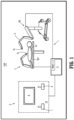
- Robotic surgical system 1 generally includes a plurality of surgical robotic arms 2, 3 having a surgical instrument, such as, for example, an electromechanical instrument 10 removably attached thereto; a control device 4; and an operating console 5 coupled with control device 4.
- Operating console 5 includes a display device 6, which is set up in particular to display three-dimensional images; and manual input devices 7, 8, by means of which a person (not shown), e.g., a clinician, is able to telemanipulate robotic arms 2, 3 in a first operating mode, as known in principle to a person skilled in the art.
- a person e.g., a clinician
- Each of the robotic arms 2, 3 may be composed of a plurality of members, which are connected through joints.
- Robotic arms 2, 3 may be driven by electric drives (not shown) that are connected to control device 4.
- Control device 4 e.g., a computer
- Control device 4 is set up to activate the drives, in particular by means of a computer program, in such a way that robotic arms 2, 3 and thus electromechanical instrument 10 (including the electromechanical end effector (not shown)) execute a desired movement according to a movement defined by means of manual input devices 7, 8.
- Control device 4 may also be set up in such a way that it regulates the movement of robotic arms 2, 3 and/or of the drives.
- Robotic surgical system 1 is configured for use on a patient "P" lying on a surgical table “ST” to be treated in a minimally invasive manner by means of a surgical instrument, e.g., electromechanical instrument 10.
- Robotic surgical system 1 may also include more or less than two robotic arms 2, 3, the additional robotic arms likewise being connected to control device 4 and being telemanipulatable by means of operating console 5.
- a surgical instrument for example, electromechanical instrument 10 (including the electromechanical end effector), may also be attached to the additional robotic arm.
- the robotic arms such as for example, robotic arm 3, is supported on a surgical cart 100.
- the surgical cart 100 may incorporate the control device 4.
- the robotic arms, such as for example, robotic arm 2 may be coupled to the surgical table "ST.”
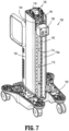
- the surgical cart 100 is configured to move robotic arm 3 ( FIG. 1 ) to a selected position within operating room "OR" ( FIG. 1 ) and to provide height adjustment of the robotic arm 3.
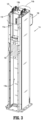
- the surgical cart 100 generally includes a cart base 102, a support column 104 extending vertically (i.e., perpendicularly) from the cart base 102, and a carriage or slider 106 slidably supported on column 104 and configured for supporting robotic arm 3 thereon.
- the support column 104 of the surgical cart 100 defines a longitudinal axis "X" and has a first end 104a supported on the cart base 102 and a second free end 104b.
- the support column 104 includes a pair of opposed sidewalls 108a, 108b.
- a pair of handles 110a, 110b is attached to respective sidewalls 108a, 108b and is configured to be grasped by a clinician to facilitate movement of the surgical cart 100 within the operating room "OR.”
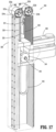
- the sidewalls 108a, 108b of the support column 104 are laterally spaced from one another to define a longitudinally-extending channel 112 having an internal support structure 114 disposed therein.
- the internal support structure 114 of the support column 104 extends along the longitudinal axis "X" of the support column 104 and is configured to slidably support both the carriage 106 and a counterweight 130.
- the internal support structure 114 of the support column 104 has a first longitudinal side 114a defining a first longitudinally-extending track 116a, and a second longitudinal side 114b defining a second longitudinally-extending track 116b.
- the carriage 106 is slidably supported in the first track 116a of the first longitudinal side 114a
- the counterweight 130 is slidably supported in the second track 116b of the second longitudinal side 114b.
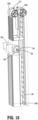
- the support column 104 includes a platform 118 disposed on the internal support structure 114, at second free end 104b of column 104, for supporting a pulley assembly 120 thereon.
- the pulleys 120a, 120b are rotatably supported on platform 118 via respective hubs 122a, 122b. It is contemplated that each of the hubs 122a, 122b may include a braking mechanism 124, such as, for example, a servomotor brake or an electromagnetic brake, configured to selectively halt rotation of the pulleys 120a, 120b. In embodiments, the hubs 122a, 122b may each include a motor 126 for driving a rotation of the pulleys 120a, 120b, thereby moving the carriage 106. A detailed description of an exemplary servomotor brake may be found in U.S. Patent No. 6,273,22 1 . In embodiments, the pulleys 120a, 120b may have an absolute encoder to determine a position of the robotic arm 3.
- a braking mechanism 124 such as, for example, a servomotor brake or an electromagnetic brake
- the pulley assembly 120 includes first and second cables 128, 132 and a toggle bar 134.
- the first cable 128 extends over the first pair of pulleys 120a
- the second cable 132 extends over the second pair of pulleys 120b.
- the first cable 128 has a first end 128a fixedly coupled to the counterweight 130, and a second end (not explicitly shown) fixedly coupled to the carriage 106.
- the second cable 132 has a first end (not explicitly shown) fixedly coupled to the counterweight 130, and a second end (not explicitly shown) fixedly coupled to the carriage 106.
- the toggle bar 134 of the pulley assembly 120 is pivotably supported on the counterweight 130.
- the toggle bar 134 has a first end 134a having the first end 128a of the first cable 128 fixed thereto, and a second end 134b having the first end of the second cable 132 fixed thereto.
- the toggle bar 134 has an intermediate portion pivotably attached to a fulcrum 136, which is attached to the counterweight 130.
- the toggle bar 134 accounts for any manufacturing tolerances or stretching in the cables 128, 132 that may occur over time. For example, if the first cable 128 begins to stretch or lengthen whereas the second cable 132 does not, the toggle bar 134 will pivot to move the first end 134a of the toggle bar 134 toward the counterweight 130 to account for the lengthening of the first cable 128. As such, even with an uneven tension in one of the cables 128, 132, the first and second cables 128, 132 continue to carry an equal load of the counterweight 130. Further, the toggle bar 134 accommodates for manufacturing tolerances in the cables 128a, 132.
- the counterweight 130 has a mass substantially equal to the combined mass of the carriage 106, the robotic arm 3, and the attached surgical instrument 10.
- the counterweight 130 may have a mass substantially equal to the combined mass of the carriage 106, the robotic arm 3, and/or the surgical instrument 10.
- the counterweight 130 functions to reduce the effort required of a clinician, or in some embodiments, a motor, in raising or lowering the carriage 106 (with the robotic arm 3 attached) along the support column 104 by making the carriage 106 free-floating.
- the counterweight 130 may include a plurality of discreet weights stacked on one another.
- Each of the weights may be detachable from the counterweight unit 130 to provide a clinician with the ability to adjust the mass of the counterweight 130 depending on the mass of the carriage 106, the robotic arm 3, and/or other components being ultimately supported by the carriage 106.
- the counterweight 106 may be considered a component of the pulley assembly 120.
- the surgical cart 100 includes a braking mechanism 140 disposed within the cavity 112 of the support column 104.
- the braking mechanism 140 includes a shaft or rod 142 and a brake 144 slidably mounted to the shaft 142.
- the shaft 142 extends longitudinally within the support column 104 and is fixed at its ends between the platform 118 and the cart base 102.
- the brake 144 has a connector or extension 146 that fixes the brake 144 to the carriage 106 such that axial movement of the carriage 106 along the track 116a of the support column 104 causes the brake 144 to slide along the shaft 142.
- a longitudinally-extending channel 148 is defined through the brake 144 and has the shaft 142 extending therethrough.
- the brake 144 may be configured as an electromagnetic brake, a servomotor brake, hydraulic, pneumatic, or the like.
- the brake 144 frictionally engages the shaft 142.
- the brake 144 may include a sensor (not explicitly shown) that senses a threshold force applied on the carriage 106 causing the brake 144 to automatically release from engagement with the shaft 142.
- the threshold force sensed by the sensor may be an upward force applied by the clinician on the carriage 106 intended to raise the carriage 106.
- the brake 144 may automatically frictionally engage the shaft 142 in the absence of the threshold force.
- the senor may be configured to detect when the motor 126 ( FIG. 5 ) of the pulley assembly 120 is being activated, or may receive a contemporaneous signal from control device 4 indicating that motor 126 is being activated. Upon the sensor sensing an activation of the motor 126 or receiving a signal from control device 4, the brake 144 releases from engagement with the shaft 142 to allow for the raising or lowering of the carriage 106 driven by the motor 126.
- the cart base 102 of the surgical cart 100 is fixed to the first end 104a of the support column 104 and includes four casters 103a, 103b, 103c, 103d.
- the cart base 102 may include more or less than four casters.
- the cart base 102 further includes two foot pedals 105a, 105b coupled to the casters 103a-103d via linkages 107a, 107b that function to rotate the casters 103a-103d in a selected direction. As such, using the foot pedals 105a, 105b, a clinician may control the direction of movement of the surgical cart 100.
- the carriage 106 may be raised or lowered to a selected vertical position along the longitudinal axis "X" of the support column 104.
- a clinician may either actuate the motor 126 in the hubs 122a, 122b of the pulley assembly 120 via the control device 4, or manually raise the carriage 106 by hand.
- the counterweight 130 of the pulley assembly 120 reduces the energy or force required to raise the carriage 106 due to the counterweight 130 acting on the carriage 106 in the same direction that the carriage 106 is being moved by the clinician or the motor 126.
- the carriage 106 With the brake 144 engaged to the shaft 142, the carriage 106 will be fixed in its vertical position on the support column 104. In the instance where the combined mass of the carriage 106, the robotic arm 3, and the surgical instrument 10 is greater than the mass of the counterweight 130, the brake 144 will prevent the carriage 106 from being lowered so long as the brake 144 is in the actuated state. In the alternative instance where the counterweight 130 is greater in mass than the combined mass of the carriage 106, the robotic arm 3, and the surgical instrument 10, the brake 144 will prevent the carriage 106 from being raised so long as the brake 144 is in the actuated state.
- the surgical cart 200 is configured to move the robotic arm 3 to a selected position within operating room "OR" ( FIG. 1 ) and to provide vertical movement of the robotic arm 3.
- the surgical cart 200 generally includes a cart base 202, a support column 204 extending vertically (e.g., perpendicularly) from the cart base 202, and a carriage or slider 206 configured for supporting the robotic arm 3 thereon. Only those components of the surgical cart 200 deemed important in elucidating features that differ from the surgical cart 100 of FIGS. 2-9 will be described in detail.
- the surgical cart 200 includes a braking mechanism 240 for selectively fixing the vertical position of the carriage 206, and in turn the robotic arm 3, relative to the support column 204.
- the braking mechanism 240 includes a ball screw assembly 242, 244 and a motorized brake 246 operably engaged to the ball screw assembly.
- the ball screw assembly includes a ball screw 242 and a ball nut 244 threadingly coupled to the ball screw 242.
- the braking mechanism 240 may include a conventional lead screw and a conventional nut threaded thereto.
- the ball screw 242 has a high pitch relative to a conventional ball screw, wherein the relative high pitch facilitates raising and lowereing of carriage 106, and in turn, robotic arm 3..
- the ball nut 244 of the braking mechanism 240 is rotatably mounted to the carriage 206 such that the nut 244 moves with the carriage 206 axially along the length of the support column 204. It is contemplated that the nut 244 may have a surface feature (not explicitly shown) defined on its outer surface that engages with a corresponding surface feature (not explicitly shown) on the carriage 206 which allows for relative rotation of the nut 244 while inhibiting relative axial movement of the nut 244.
- the nut 244 is threadingly coupled to the ball screw 242 such that axial movement of the nut 244 along the ball screw 242 causes the ball screw 242 to rotate about its longitudinal axis.
- the ball screw 242 of the braking mechanism 240 extends longitudinally within the support column 204 and is axially fixed at its ends between a platform 248 and the brake 246 of the braking mechanism 240.
- the brake 246 of the braking mechanism 240 is mounted on the end of the ball screw 242 and may be an electromagnetic brake, a servomotor brake, or the like.
- the brake 246 defines a longitudinally-extending channel 250 having the end of the ball screw 242 extending therethrough.
- the brake 246 is configured to selectively frictionally engage the ball screw 242 in response to an actuation of the brake 246 via the control device 4.
- the brake 246 may include a sensor (not explicitly shown) that controls the actuation of the brake 246.
- the sensor may be configured to sense a threshold force applied on the carriage 206 and in response cause the brake 246 to automatically release from engagement with the ball screw 242.
- the threshold force sensed by the sensor may be caused by a clinician applying an upward force on the carriage 206 intended to raise the carriage 206.
- the brake 246 may be further configured to automatically frictionally engage the ball screw 242 in the absence of the threshold force.
- the sensor controls the brake 246 of the braking mechanism 240 for selectively fixing the vertical position of the carriage 206 on the support column 204.
- a processor (not explicitly shown) may be provided to direct the operation of the brake 246 in response to the sensor sensing the threshold force.
- the surgical cart 200 may further include a motor 252 operably coupled to the ball screw 242 to effect a rotation of the ball screw 242.
- a motor 252 operably coupled to the ball screw 242 to effect a rotation of the ball screw 242.
- an activation of the motor 252 causes the ball screw 242 to rotate, thereby driving an upward or downward movement of the nut 244 along the ball screw 242 and, in turn, a corresponding upward or downward movement of the carriage 206.
- the sensor may be configured to detect when the motor 252 is being activated and upon the sensor sensing the activation of the motor 252, the brake 246 may be configured to automatically release from engagement with the ball screw 242 to allow for the raising or lowering of the carriage 206 by the motor 252.
- another brake (not shown) may be provided that selectively engages the nut 244 to prevent rotation of the nut 244 and/or axial translation of the nut 244.
- a clinician may either manually apply a force on the carriage 206, or the motor 252 may be activated by a clinician pressing a button to drive the carriage 206 movement.
- the sensor senses either the manual force being applied on the carriage 206, or the sensor senses an activation of the motor 252.
- the sensor communicates with the processor, which then directs the brake 246 of the braking mechanism 240 to release the ball screw 242. If vertical adjustment of the carriage 206 is being driven manually, the force applied on the carriage 206 by the clinician moves the carriage 206 and the attached nut 244 and robotic arm 3, along the ball screw 242 since the ball screw 242 is no longer being prevented from rotating by the brake 246.
- the activation of the motor 252 rotates the ball screw 242 since the ball screw 242 is no longer being prevented from rotating by the brake 246.
- the nut 244 moves along the ball screw 242, thereby moving the carriage 206 and the attached robotic arm 3 along the support column 204.
- the braking mechanism 260 includes a linear motion brake mounted to the carriage 206 and movable therewith.
- the linear motion brake includes a pair of clamp arms 262a, 262b that selectively grasp a track 205 of the support column 204 to halt axial movement of the carriage 206 along the track 205.
- the linear motion brake may include a manual actuator 264 operable by a clinician to manually actuate the linear brake.
- a detail description of an exemplary linear motion brake may be found in U.S. Patent No. 8,220,592 .
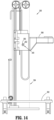
- a surgical cart 300 of robotic surgical system 1 configured for use in accordance with the present disclosure.
- the surgical cart 300 is configured to move the robotic arm 3 to a selected position within the operating room "OR" ( FIG. 1 ) and to provide vertical movement of the robotic arm 3.
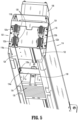
- the surgical cart 300 generally includes a cart base 302, a support column 304 extending vertically (e.g., perpendicularly) from the cart base 302, and a carriage or slider 306 configured for supporting the robotic arm 3 thereon. Only those components of the surgical cart 300 deemed important in elucidating features that differ from the surgical cart 100 of FIGS. 2-9 will be described in detail.
- the surgical cart 300 includes a braking mechanism 340, similar to the braking mechanism 240 described with reference to FIG 11 .
- the braking mechanism 340 is configured to fix the vertical position of the carriage 306, and in turn the robotic arm 3, relative to the support column 304.
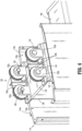
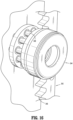
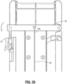
- the braking mechanism 340 includes a rack 342 and pinion 344 operably coupled to one another to selectively halt axial movement of the carriage 306 along the support column 304.
- the rack 342 of the braking mechanism 340 is fixedly mounted to the support column 304 and extends parallel with the longitudinal axis of the support column 304.
- the rack 342 defines a plurality of teeth 346 along its length configured to meshingly engage with bars 348 of the pinion 344.
- the pinion 344 of the braking mechanism 340 is non-rotatably mounted to an axle 350 that is rotatably mounted to the carriage 306. As such, the pinion 344 is able to rotate relative to the carriage 306 while being axially fixed relative to the carriage 306.
- the axle 350 is rotatably fixed relative to the carriage 306 while the pinion 344 is rotatably mounted to the axle 350.
- the pinion 344 may have helical teeth for reducing backlash.
- the braking mechanism 340 further includes a brake 352 mounted to an end of the axle 350.
- the brake 352 may be an electromagnetic brake, a servomotor brake, or the like, and is configured to selectively frictionally engage the pinion 344 in response to an actuation of the brake 344 via the control device 4.
- the brake 344 may include a sensor (not explicitly shown) that controls the actuation of the brake 344.
- the sensor may be configured to sense a threshold force applied on the carriage 306 and in response cause the brake 352 to automatically release from engagement with the pinion 344.
- the threshold force sensed by the sensor may be caused by a clinician applying an upward force on the carriage 306 intended to raise the carriage 306.
- the brake 352 may be further configured to automatically frictionally engage the pinion 344 in the absence of the threshold force.
- the sensor controls the brake 352 of the braking mechanism 340 for selectively fixing the vertical position of the carriage 306 on the support column 304.
- a processor e.g., the control device 4, may be provided to direct the operation of the brake 352 in response to the sensor sensing the threshold force.
- the support column 304 may further include a motor (not explicitly shown) operably coupled to the pinion 344 or the axle 350 to effect a rotation of the pinion 344 either directly, or indirectly via the axle 350.
- a motor (not explicitly shown) operably coupled to the pinion 344 or the axle 350 to effect a rotation of the pinion 344 either directly, or indirectly via the axle 350.
- an activation of the motor causes the pinion 344 to rotate, thereby driving an upward or downward movement of the pinion 344 along the rack 342, and in turn, a corresponding upward or downward movement of the carriage 306 along the support column 304.
- the sensor may be configured to detect when the motor is being activated and upon the sensor sensing an activation of the motor, the brake 352 may automatically release from engagement with the pinion 344 to allow for the raising or lowering of the carriage 306.
- the processor may be configured to direct the operation of the brake 352 in response to the sensor sensing an activation or deactivation of the motor.
- both the axle 350 and the pinion 344 may be non-rotatable relative to the carriage 306.
- the pinion 344 is movable between a first or braking position in which the pinion 344 is engaged to the rack 342, and a second or non-braking position in which the pinion 344 is disengaged from the rack 342.
- the pinion 344 acts as the brake 352 by being selectively engaged with the rack 342 to halt movement of the carriage 306 along the support column 304.
- a clinician may either manually apply a force on the carriage 306, or the motor may be activated to drive the carriage 306 movement.
- the sensor senses either the manual force being applied on the carriage 306 by the clinician, or the sensor senses an activation of the motor.
- the sensor communicates with the processor, which then directs the brake 352 of the braking mechanism 340 to release the pinion 344. If vertical adjustment of the carriage 306 is being driven manually, the force applied on the carriage 306 by the clinician moves the carriage 306, the attached robotic arm 3, and the pinion 344, along the support column 304 since the pinion 344 is no longer being prevented from rotating by the brake 352.
- the activation of the motor rotates the pinion 344 since the pinion 344 is no longer being prevented from rotating by the brake 352.
- the pinion 344 rotates, the pinion 344 moves axially along the rack 342, thereby moving the carriage 306 and the attached robotic arm 3 along the support column 304.
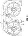
- the surgical cart 300 includes a pair of spring members 320a, 320b mounted in the support column 304 and configured to counterbalance the combined mass of the carriage 306 and the attached robotic arm 3.
- Each of the spring members 320a, 320b may be constant force springs having one or more laminations or layers fabricated from stainless steel, fiberglass, or any suitable material. The number and thickness of the laminations and the type of material used to fabricate the constant-force springs 320a, 320b is selected based on the combined mass of the carriage 306, the robotic arm 3, and the attached surgical instrument.
- the constant-force springs 320a, 320b are each coiled about a drum 322a, 322b.
- the two drums 322a, 322b are disposed adjacent one another and are each rotatably mounted to a respective axle or pivot pin 324a, 324b.
- a first end of each of the springs is secured (e.g., bolted or soldered) to the respective drum 322a, 322b, and a second end 326, 328 of each of the springs 320a, 320b extends downwardly from the respective drum 322a, 322b.
- One or both of the second ends 326, 328 of the springs 320a, 320b are directly attached to the carriage 306.
- the springs 320a, 320b function to reduce the effort required of a clinician, or in some embodiments, a motor, in raising or lowering the carriage 306 (with the robotic arm 3 attached) along the support column 304 by making the carriage 306 free-floating.
- electrical switches 341 such as, for example, hall effect sensors, may be associated with the springs 320a, 320b used to detect if the springs 320a, 320b break.
- the respective electrical switch 341 would be activated, thereby providing a signal or the like to the clinician or technician that there has been a failure, and, in embodiments, the system is placed in a permanent or temporary "hold” or “shut-down” state, until the particular robotic cart 300 is replaced and/or repaired.
- the carriage 306 may be raised or lowered to a selected position along the longitudinal axis of the support column 304. For example, to lower the carriage 306, a threshold amount of force is required to overcome the spring force of the springs 320a, 320b. Upon overcoming the spring force of the springs 320a, 320b, the carriage 306 is lowered away from the drums 322a, 322b, thereby uncoiling the springs 320a, 320b.
- a brake such as, for example, the braking mechanism 340, may be used to maintain the carriage 306 in the selected vertical position on the support column 304.
- the brake is released allowing the spring force of the springs 320a, 320b to act on the carriage 306.
- the springs 320a, 320b attempt to return to their natural, coiled state, the springs 320a, 320b exert an upwardly-oriented force on the carriage 306 to facilitate upward vertical movement of the carriage 306 along the support column 304.
- the springs 320a, 320b reduce the energy required to raise the carriage 306 due to the springs 320a, 320b acting on the carriage 306 in the same direction the carriage 306 is being moved by the clinician or the motor.
- the cart 300 may further include an overlatch mechanism for adjusting the force required to rotate the pinion 344 of the braking mechanism 340.
- the overlatch mechanism includes a cable 330, a lever 331, and a pivot arm 333 ( FIG. 20 ).
- the cable 330 has a first end 330a anchored to the lever 331, and a second end 330b anchored to a base of the support column 304.
- the cable 330 is wrapped about the pinion 344 of the braking mechanism 340 to provide a selective amount of resistance to rotation of the pinion 344.
- the lever 331 is actuated, which causes the pivot arm 333 to pivot downwardly, thereby bringing the first end 330a of the cable 330 closer to the second end 330b. In this way, the cable 330 loosens about the pinion 344 to allow the pinion 344 to more easily rotate.
- surgical carts 100, 200, 300 of the present disclosure may incorporate any of the braking mechanisms described above for holding the carriage in a selected vertical position along the support column.
Landscapes
- Engineering & Computer Science (AREA)
- Health & Medical Sciences (AREA)
- Surgery (AREA)
- Life Sciences & Earth Sciences (AREA)
- Robotics (AREA)
- Mechanical Engineering (AREA)
- Medical Informatics (AREA)
- Heart & Thoracic Surgery (AREA)
- Biomedical Technology (AREA)
- Molecular Biology (AREA)
- Animal Behavior & Ethology (AREA)
- General Health & Medical Sciences (AREA)
- Public Health (AREA)
- Veterinary Medicine (AREA)
- Nuclear Medicine, Radiotherapy & Molecular Imaging (AREA)
- Oral & Maxillofacial Surgery (AREA)
- Pathology (AREA)
- Manipulator (AREA)
- Apparatus For Radiation Diagnosis (AREA)
Claims (2)
- Chariot chirurgical (300) destiné à supporter un bras robotique (3), comprenant :une colonne de support (304) s'étendant verticalement et définissant un axe longitudinal ;un chariot (306) accouplé de manière mobile à la colonne de support et conçu pour porter un bras robotique ; etun mécanisme de freinage (340) comportant :une crémaillère (342) fixée à la colonne de support ; etun pignon (344) monté sur le chariot et conçu pour s'accoupler de manière fonctionnelle à la crémaillère de sorte que le mouvement axial du chariot le long de l'axe longitudinal défini par la colonne de support est empêché en réponse à l'arrêt de la rotation du pignon, dans lequel le mécanisme de freinage comporte un frein (352) accouplé au pignon et conçu pour se déplacer par rapport au pignon entre une première position dans laquelle le pignon est autorisé à tourner et une seconde position dans laquelle le frein empêche le pignon de tourner par rapport au frein ; oudans lequel le pignon est accouplé de manière à ne pas pouvoir tourner au chariot et est sélectivement mobile par rapport à la crémaillère entre une première position ou position de freinage dans laquelle le pignon est accouplé de manière fonctionnelle à la crémaillère, et une seconde position ou position de non-freinage dans laquelle le pignon est désaccouplé de la crémaillère ;le chariot comprenant en outre un ensemble de poulies (120) comportant :une première poulie (120a) supportée par la colonne de support ;un premier câble (128) s'étendant sur la première poulie et ayant une première extrémité fixée au chariot et une seconde extrémité ; etun contrepoids (130) fixé à la seconde extrémité du premier câble, une seconde poulie (120b) supportée par la colonne de support ;un second câble (132) s'étendant sur la seconde poulie et ayant une première extrémité fixée au chariot et une seconde extrémité fixée au contrepoids ; etdans lequel l'ensemble de poulies comporte une barre à bascule (134) accouplée de manière à pouvoir pivoter au contrepoids, la barre à bascule comportant une première extrémité (134a) à laquelle est fixée la seconde extrémité du premier câble, et une seconde extrémité (134b) à laquelle est fixée la seconde extrémité du second câble.
- Chariot chirurgical selon la revendication 1, dans lequel le contrepoids comporte une pluralité de poids discrets dans une configuration empilée et détachables les uns des autres.
Applications Claiming Priority (2)
| Application Number | Priority Date | Filing Date | Title |
|---|---|---|---|
| US201862658101P | 2018-04-16 | 2018-04-16 | |
| PCT/US2019/024509 WO2019203999A1 (fr) | 2018-04-16 | 2019-03-28 | Systèmes chirurgicaux robotiques et leurs chariots de bras robotisés |
Publications (3)
| Publication Number | Publication Date |
|---|---|
| EP3781069A1 EP3781069A1 (fr) | 2021-02-24 |
| EP3781069A4 EP3781069A4 (fr) | 2022-01-12 |
| EP3781069B1 true EP3781069B1 (fr) | 2025-04-30 |
Family
ID=68239768
Family Applications (1)
| Application Number | Title | Priority Date | Filing Date |
|---|---|---|---|
| EP19789524.6A Active EP3781069B1 (fr) | 2018-04-16 | 2019-03-28 | Systèmes chirurgicaux robotiques et leurs chariots de bras robotisés |
Country Status (4)
| Country | Link |
|---|---|
| US (1) | US11944510B2 (fr) |
| EP (1) | EP3781069B1 (fr) |
| CN (1) | CN111970988B (fr) |
| WO (1) | WO2019203999A1 (fr) |
Families Citing this family (9)
| Publication number | Priority date | Publication date | Assignee | Title |
|---|---|---|---|---|
| CN111971150A (zh) | 2018-04-20 | 2020-11-20 | 柯惠Lp公司 | 手术机器人手推车放置的系统和方法 |
| EP3998968B1 (fr) | 2019-07-15 | 2025-08-06 | Stryker Corporation | Systèmes associés à un instrument chirurgical robotique à main |
| CN112568934B (zh) * | 2019-09-30 | 2025-03-25 | 通用电气精准医疗有限责任公司 | 一种成像装置及其成像方法 |
| CN113017839B (zh) * | 2021-02-01 | 2022-07-26 | 武汉中科医疗科技工业技术研究院有限公司 | 升降立柱以及手术机器人 |
| DE112022003390T5 (de) * | 2021-07-02 | 2024-06-06 | Covidien Lp | Robotische operationssysteme und roboterarmwagen dafür |
| CN113855255B (zh) * | 2021-10-27 | 2023-03-07 | 哈尔滨思哲睿智能医疗设备股份有限公司 | 升降旋转机构、机械臂及主从手术机器人 |
| CN115153856B (zh) * | 2022-07-29 | 2026-02-03 | 上海卓昕医疗科技有限公司 | 一种机械臂及其移动控制方法 |
| CN118000919B (zh) * | 2024-04-08 | 2024-08-02 | 江苏长友特钢机械有限公司 | 一种手术机械臂 |
| WO2025257679A1 (fr) * | 2024-06-11 | 2025-12-18 | Covidien Lp | Chariot de bras robotique chirurgical |
Citations (1)
| Publication number | Priority date | Publication date | Assignee | Title |
|---|---|---|---|---|
| US20010013764A1 (en) * | 1998-08-04 | 2001-08-16 | Blumenkranz Steven J. | Manipulator positioning linkage for robotic surgery |
Family Cites Families (15)
| Publication number | Priority date | Publication date | Assignee | Title |
|---|---|---|---|---|
| KR100354380B1 (ko) | 2000-04-18 | 2002-09-28 | 주식회사 이성건설기계 | 승강기용 브레이크장치 |
| US7891935B2 (en) | 2002-05-09 | 2011-02-22 | Brooks Automation, Inc. | Dual arm robot |
| US20070029142A1 (en) | 2005-08-03 | 2007-02-08 | Drennen David B | Brake system including ball screw and nut assembly |
| US8607935B2 (en) | 2005-12-20 | 2013-12-17 | Intuitive Surgical Operations, Inc. | Guide systems for laminated spring assemblies |
| EP1815950A1 (fr) | 2006-02-03 | 2007-08-08 | The European Atomic Energy Community (EURATOM), represented by the European Commission | Dispositif chirurgical robotique pour effectuer des techniques opératoires minimalement invasive |
| US20100243344A1 (en) * | 2006-09-25 | 2010-09-30 | Board Of Trustees Of Leland Stanford Junior University | Electromechanically counterbalanced humanoid robotic system |
| DE102008059331B4 (de) | 2008-11-27 | 2012-05-31 | Siemens Aktiengesellschaft | Stativ, insbesondere Bodenstativ |
| US8672543B2 (en) * | 2010-04-13 | 2014-03-18 | Carestream Health, Inc. | Counterweight for mobile x-ray device |
| CN112842538B (zh) * | 2013-03-15 | 2024-09-10 | 直观外科手术操作公司 | 具有操控界面的外科患者侧手推车 |
| CN103896183B (zh) | 2014-03-04 | 2016-08-24 | 唐山开元机器人系统有限公司 | 一种竖轴上下移动轻阻力、防失速的升降装置 |
| US10201390B2 (en) | 2014-03-17 | 2019-02-12 | Intuitive Surgical Operations, Inc. | Command shaping to dampen vibrations in mode transitions |
| EP2957272B1 (fr) | 2014-05-19 | 2020-03-11 | The University of Dundee | Système basé au sol de support d'équipement médical |
| CN105361951B (zh) * | 2015-12-14 | 2017-11-14 | 山东科技大学 | 一种微创腹腔手术持镜机器人 |
| US10034721B1 (en) | 2017-09-27 | 2018-07-31 | Verb Surgical Inc. | Robotic arm cart having shock absorbing mechanisms and uses therefor |
| JP6469304B1 (ja) | 2018-10-23 | 2019-02-13 | 株式会社A−Traction | 手術支援装置、その制御方法及びプログラム |
-
2019
- 2019-03-28 WO PCT/US2019/024509 patent/WO2019203999A1/fr not_active Ceased
- 2019-03-28 CN CN201980025013.5A patent/CN111970988B/zh active Active
- 2019-03-28 EP EP19789524.6A patent/EP3781069B1/fr active Active
- 2019-03-28 US US17/047,788 patent/US11944510B2/en active Active
Patent Citations (1)
| Publication number | Priority date | Publication date | Assignee | Title |
|---|---|---|---|---|
| US20010013764A1 (en) * | 1998-08-04 | 2001-08-16 | Blumenkranz Steven J. | Manipulator positioning linkage for robotic surgery |
Also Published As
| Publication number | Publication date |
|---|---|
| US11944510B2 (en) | 2024-04-02 |
| CN111970988B (zh) | 2024-11-05 |
| EP3781069A1 (fr) | 2021-02-24 |
| CN111970988A (zh) | 2020-11-20 |
| WO2019203999A1 (fr) | 2019-10-24 |
| US20210153973A1 (en) | 2021-05-27 |
Similar Documents
| Publication | Publication Date | Title |
|---|---|---|
| EP3781069B1 (fr) | Systèmes chirurgicaux robotiques et leurs chariots de bras robotisés | |
| US10737062B2 (en) | Auto lock for catheter handle | |
| JP5630879B2 (ja) | 伸展性外科手術デバイス | |
| EP1123690B1 (fr) | Commandes d'inclinaisons procédurales pour brancard | |
| JP6710683B2 (ja) | 患者支持システムおよびそのような患者支持システム用のレベリングシステム | |
| EP2085062A2 (fr) | Poignée poussoir dotée d'une tige de poignée pivotante | |
| US20250213409A1 (en) | Devices and methods for transferring an object | |
| WO2019164856A1 (fr) | Systèmes et procédés de contrôle d'effecteurs d'extrémité | |
| CA3022165A1 (fr) | Ensembles chirurgicaux robotiques et unites d'entrainement d'instrument associees | |
| KR20160135278A (ko) | 액티브 바이어스를 가진 일정 힘 스프링 | |
| CN111565664B (zh) | 手术机器人臂及其滑轮组件 | |
| US7857778B2 (en) | Apparatus for physiotherapeutic treatment | |
| US8092402B2 (en) | Power assist control method, power assist control apparatus, and reduction apparatus | |
| CN111227946A (zh) | 一种微创血管介入手术机器人操作装置 | |
| US20220104915A1 (en) | Robotic surgical systems and robotic arm carts thereof | |
| JPH09238931A (ja) | X線診断装置 | |
| JP2024054315A (ja) | 外科手術器具の制御 | |
| JPWO2021046658A5 (fr) | ||
| GB2522120A (en) | Medical instrument with a flexible toothed belt | |
| KR102772511B1 (ko) | 환자의 안전이 강화된 재활치료용 로봇 | |
| CA2088388A1 (fr) | Dispositif de securite pour appareil servant a lever et a descendre des charges | |
| JP2002165846A (ja) | 医療台 | |
| KR102150633B1 (ko) | 컨트롤 암 구조 및 컨트롤 암 설계방법 |
Legal Events
| Date | Code | Title | Description |
|---|---|---|---|
| STAA | Information on the status of an ep patent application or granted ep patent |
Free format text: STATUS: THE INTERNATIONAL PUBLICATION HAS BEEN MADE |
|
| PUAI | Public reference made under article 153(3) epc to a published international application that has entered the european phase |
Free format text: ORIGINAL CODE: 0009012 |
|
| STAA | Information on the status of an ep patent application or granted ep patent |
Free format text: STATUS: REQUEST FOR EXAMINATION WAS MADE |
|
| 17P | Request for examination filed |
Effective date: 20201113 |
|
| AK | Designated contracting states |
Kind code of ref document: A1 Designated state(s): AL AT BE BG CH CY CZ DE DK EE ES FI FR GB GR HR HU IE IS IT LI LT LU LV MC MK MT NL NO PL PT RO RS SE SI SK SM TR |
|
| AX | Request for extension of the european patent |
Extension state: BA ME |
|
| DAV | Request for validation of the european patent (deleted) | ||
| DAX | Request for extension of the european patent (deleted) | ||
| A4 | Supplementary search report drawn up and despatched |
Effective date: 20211214 |
|
| RIC1 | Information provided on ipc code assigned before grant |
Ipc: A61B 50/26 20160101ALN20211208BHEP Ipc: B25J 19/00 20060101ALI20211208BHEP Ipc: B25J 9/10 20060101ALI20211208BHEP Ipc: B25J 5/00 20060101ALI20211208BHEP Ipc: A61B 90/50 20160101ALI20211208BHEP Ipc: A61B 34/35 20160101ALI20211208BHEP Ipc: A61B 50/13 20160101AFI20211208BHEP |
|
| GRAP | Despatch of communication of intention to grant a patent |
Free format text: ORIGINAL CODE: EPIDOSNIGR1 |
|
| STAA | Information on the status of an ep patent application or granted ep patent |
Free format text: STATUS: GRANT OF PATENT IS INTENDED |
|
| RIC1 | Information provided on ipc code assigned before grant |
Ipc: A61B 50/26 20160101ALN20241028BHEP Ipc: B25J 19/00 20060101ALI20241028BHEP Ipc: B25J 9/10 20060101ALI20241028BHEP Ipc: B25J 5/00 20060101ALI20241028BHEP Ipc: A61B 90/50 20160101ALI20241028BHEP Ipc: A61B 34/35 20160101ALI20241028BHEP Ipc: A61B 50/13 20160101AFI20241028BHEP |
|
| RIC1 | Information provided on ipc code assigned before grant |
Ipc: A61B 50/26 20160101ALN20241112BHEP Ipc: B25J 19/00 20060101ALI20241112BHEP Ipc: B25J 9/10 20060101ALI20241112BHEP Ipc: B25J 5/00 20060101ALI20241112BHEP Ipc: A61B 90/50 20160101ALI20241112BHEP Ipc: A61B 34/35 20160101ALI20241112BHEP Ipc: A61B 50/13 20160101AFI20241112BHEP |
|
| INTG | Intention to grant announced |
Effective date: 20241128 |
|
| GRAS | Grant fee paid |
Free format text: ORIGINAL CODE: EPIDOSNIGR3 |
|
| GRAA | (expected) grant |
Free format text: ORIGINAL CODE: 0009210 |
|
| STAA | Information on the status of an ep patent application or granted ep patent |
Free format text: STATUS: THE PATENT HAS BEEN GRANTED |
|
| AK | Designated contracting states |
Kind code of ref document: B1 Designated state(s): AL AT BE BG CH CY CZ DE DK EE ES FI FR GB GR HR HU IE IS IT LI LT LU LV MC MK MT NL NO PL PT RO RS SE SI SK SM TR |
|
| REG | Reference to a national code |
Ref country code: CH Ref legal event code: EP Ref country code: GB Ref legal event code: FG4D |
|
| REG | Reference to a national code |
Ref country code: IE Ref legal event code: FG4D |
|
| REG | Reference to a national code |
Ref country code: DE Ref legal event code: R096 Ref document number: 602019069370 Country of ref document: DE |
|
| REG | Reference to a national code |
Ref country code: NL Ref legal event code: MP Effective date: 20250430 |
|
| REG | Reference to a national code |
Ref country code: AT Ref legal event code: MK05 Ref document number: 1789340 Country of ref document: AT Kind code of ref document: T Effective date: 20250430 |
|
| PG25 | Lapsed in a contracting state [announced via postgrant information from national office to epo] |
Ref country code: FI Free format text: LAPSE BECAUSE OF FAILURE TO SUBMIT A TRANSLATION OF THE DESCRIPTION OR TO PAY THE FEE WITHIN THE PRESCRIBED TIME-LIMIT Effective date: 20250430 Ref country code: PT Free format text: LAPSE BECAUSE OF FAILURE TO SUBMIT A TRANSLATION OF THE DESCRIPTION OR TO PAY THE FEE WITHIN THE PRESCRIBED TIME-LIMIT Effective date: 20250901 Ref country code: ES Free format text: LAPSE BECAUSE OF FAILURE TO SUBMIT A TRANSLATION OF THE DESCRIPTION OR TO PAY THE FEE WITHIN THE PRESCRIBED TIME-LIMIT Effective date: 20250430 |
|
| REG | Reference to a national code |
Ref country code: LT Ref legal event code: MG9D |
|
| PG25 | Lapsed in a contracting state [announced via postgrant information from national office to epo] |
Ref country code: NO Free format text: LAPSE BECAUSE OF FAILURE TO SUBMIT A TRANSLATION OF THE DESCRIPTION OR TO PAY THE FEE WITHIN THE PRESCRIBED TIME-LIMIT Effective date: 20250730 Ref country code: GR Free format text: LAPSE BECAUSE OF FAILURE TO SUBMIT A TRANSLATION OF THE DESCRIPTION OR TO PAY THE FEE WITHIN THE PRESCRIBED TIME-LIMIT Effective date: 20250731 |
|
| PG25 | Lapsed in a contracting state [announced via postgrant information from national office to epo] |
Ref country code: PL Free format text: LAPSE BECAUSE OF FAILURE TO SUBMIT A TRANSLATION OF THE DESCRIPTION OR TO PAY THE FEE WITHIN THE PRESCRIBED TIME-LIMIT Effective date: 20250430 Ref country code: NL Free format text: LAPSE BECAUSE OF FAILURE TO SUBMIT A TRANSLATION OF THE DESCRIPTION OR TO PAY THE FEE WITHIN THE PRESCRIBED TIME-LIMIT Effective date: 20250430 |
|
| PG25 | Lapsed in a contracting state [announced via postgrant information from national office to epo] |
Ref country code: BG Free format text: LAPSE BECAUSE OF FAILURE TO SUBMIT A TRANSLATION OF THE DESCRIPTION OR TO PAY THE FEE WITHIN THE PRESCRIBED TIME-LIMIT Effective date: 20250430 |
|
| PG25 | Lapsed in a contracting state [announced via postgrant information from national office to epo] |
Ref country code: HR Free format text: LAPSE BECAUSE OF FAILURE TO SUBMIT A TRANSLATION OF THE DESCRIPTION OR TO PAY THE FEE WITHIN THE PRESCRIBED TIME-LIMIT Effective date: 20250430 |
|
| PG25 | Lapsed in a contracting state [announced via postgrant information from national office to epo] |
Ref country code: AT Free format text: LAPSE BECAUSE OF FAILURE TO SUBMIT A TRANSLATION OF THE DESCRIPTION OR TO PAY THE FEE WITHIN THE PRESCRIBED TIME-LIMIT Effective date: 20250430 |
|
| PG25 | Lapsed in a contracting state [announced via postgrant information from national office to epo] |
Ref country code: RS Free format text: LAPSE BECAUSE OF FAILURE TO SUBMIT A TRANSLATION OF THE DESCRIPTION OR TO PAY THE FEE WITHIN THE PRESCRIBED TIME-LIMIT Effective date: 20250731 |
|
| PG25 | Lapsed in a contracting state [announced via postgrant information from national office to epo] |
Ref country code: IS Free format text: LAPSE BECAUSE OF FAILURE TO SUBMIT A TRANSLATION OF THE DESCRIPTION OR TO PAY THE FEE WITHIN THE PRESCRIBED TIME-LIMIT Effective date: 20250830 |
|
| PG25 | Lapsed in a contracting state [announced via postgrant information from national office to epo] |
Ref country code: LV Free format text: LAPSE BECAUSE OF FAILURE TO SUBMIT A TRANSLATION OF THE DESCRIPTION OR TO PAY THE FEE WITHIN THE PRESCRIBED TIME-LIMIT Effective date: 20250430 |
|
| PG25 | Lapsed in a contracting state [announced via postgrant information from national office to epo] |
Ref country code: DK Free format text: LAPSE BECAUSE OF FAILURE TO SUBMIT A TRANSLATION OF THE DESCRIPTION OR TO PAY THE FEE WITHIN THE PRESCRIBED TIME-LIMIT Effective date: 20250430 Ref country code: SM Free format text: LAPSE BECAUSE OF FAILURE TO SUBMIT A TRANSLATION OF THE DESCRIPTION OR TO PAY THE FEE WITHIN THE PRESCRIBED TIME-LIMIT Effective date: 20250430 |
|
| PG25 | Lapsed in a contracting state [announced via postgrant information from national office to epo] |
Ref country code: CZ Free format text: LAPSE BECAUSE OF FAILURE TO SUBMIT A TRANSLATION OF THE DESCRIPTION OR TO PAY THE FEE WITHIN THE PRESCRIBED TIME-LIMIT Effective date: 20250430 |
|
| PG25 | Lapsed in a contracting state [announced via postgrant information from national office to epo] |
Ref country code: EE Free format text: LAPSE BECAUSE OF FAILURE TO SUBMIT A TRANSLATION OF THE DESCRIPTION OR TO PAY THE FEE WITHIN THE PRESCRIBED TIME-LIMIT Effective date: 20250430 |
|
| PG25 | Lapsed in a contracting state [announced via postgrant information from national office to epo] |
Ref country code: RO Free format text: LAPSE BECAUSE OF FAILURE TO SUBMIT A TRANSLATION OF THE DESCRIPTION OR TO PAY THE FEE WITHIN THE PRESCRIBED TIME-LIMIT Effective date: 20250430 Ref country code: SK Free format text: LAPSE BECAUSE OF FAILURE TO SUBMIT A TRANSLATION OF THE DESCRIPTION OR TO PAY THE FEE WITHIN THE PRESCRIBED TIME-LIMIT Effective date: 20250430 |
|
| PG25 | Lapsed in a contracting state [announced via postgrant information from national office to epo] |
Ref country code: IT Free format text: LAPSE BECAUSE OF FAILURE TO SUBMIT A TRANSLATION OF THE DESCRIPTION OR TO PAY THE FEE WITHIN THE PRESCRIBED TIME-LIMIT Effective date: 20250430 |