EP3780801B1 - Benutzervorrichtung und drahtlose basisstation - Google Patents
Benutzervorrichtung und drahtlose basisstation Download PDFInfo
- Publication number
- EP3780801B1 EP3780801B1 EP18913942.1A EP18913942A EP3780801B1 EP 3780801 B1 EP3780801 B1 EP 3780801B1 EP 18913942 A EP18913942 A EP 18913942A EP 3780801 B1 EP3780801 B1 EP 3780801B1
- Authority
- EP
- European Patent Office
- Prior art keywords
- srs
- csi
- transmission
- radio resources
- time alignment
- Prior art date
- Legal status (The legal status is an assumption and is not a legal conclusion. Google has not performed a legal analysis and makes no representation as to the accuracy of the status listed.)
- Active
Links
Images


Classifications
-
- H—ELECTRICITY
- H04—ELECTRIC COMMUNICATION TECHNIQUE
- H04L—TRANSMISSION OF DIGITAL INFORMATION, e.g. TELEGRAPHIC COMMUNICATION
- H04L5/00—Arrangements affording multiple use of the transmission path
- H04L5/003—Arrangements for allocating sub-channels of the transmission path
- H04L5/0078—Timing of allocation
-
- H—ELECTRICITY
- H04—ELECTRIC COMMUNICATION TECHNIQUE
- H04W—WIRELESS COMMUNICATION NETWORKS
- H04W72/00—Local resource management
- H04W72/04—Wireless resource allocation
- H04W72/044—Wireless resource allocation based on the type of the allocated resource
- H04W72/0446—Resources in time domain, e.g. slots or frames
-
- H—ELECTRICITY
- H04—ELECTRIC COMMUNICATION TECHNIQUE
- H04L—TRANSMISSION OF DIGITAL INFORMATION, e.g. TELEGRAPHIC COMMUNICATION
- H04L5/00—Arrangements affording multiple use of the transmission path
- H04L5/003—Arrangements for allocating sub-channels of the transmission path
- H04L5/0048—Allocation of pilot signals, i.e. of signals known to the receiver
-
- H—ELECTRICITY
- H04—ELECTRIC COMMUNICATION TECHNIQUE
- H04L—TRANSMISSION OF DIGITAL INFORMATION, e.g. TELEGRAPHIC COMMUNICATION
- H04L5/00—Arrangements affording multiple use of the transmission path
- H04L5/003—Arrangements for allocating sub-channels of the transmission path
- H04L5/0053—Allocation of signalling, i.e. of overhead other than pilot signals
- H04L5/0057—Physical resource allocation for CQI
-
- H—ELECTRICITY
- H04—ELECTRIC COMMUNICATION TECHNIQUE
- H04W—WIRELESS COMMUNICATION NETWORKS
- H04W72/00—Local resource management
- H04W72/04—Wireless resource allocation
-
- H—ELECTRICITY
- H04—ELECTRIC COMMUNICATION TECHNIQUE
- H04W—WIRELESS COMMUNICATION NETWORKS
- H04W72/00—Local resource management
- H04W72/20—Control channels or signalling for resource management
- H04W72/21—Control channels or signalling for resource management in the uplink direction of a wireless link, i.e. towards the network
-
- H—ELECTRICITY
- H04—ELECTRIC COMMUNICATION TECHNIQUE
- H04W—WIRELESS COMMUNICATION NETWORKS
- H04W56/00—Synchronisation arrangements
- H04W56/001—Synchronization between nodes
Definitions
- the present invention relates to a terminal and a radio base station capable of performing radio communication.
- LTE Long Term Evolution
- NR 5G New Radio
- Semi-Persistent is newly defined as a method for transmitting a report of Channel State Information (CSI) and Sounding Reference Signal (SRS) (see Non-Patent Document 1).
- CSI Channel State Information
- SRS Sounding Reference Signal
- a user equipment upon receiving a request from a radio base station (gNB), a user equipment (UE) performs the CSI reporting and SRS transmission in each set period.
- gNB radio base station
- UE user equipment
- Non-Patent Document 1 3GPP TS 38.331. V15.0.0 3rd Generation Partnership Project; Technical Specification Group Radio Access Network NR Radio Resource Control (RRC) protocol specification (Release 15), 3GPP, December 2017 .
- RRC Radio Resource Control
- 3GPP R1-1710938 relates to reference signals for new radio(NR): CSI-RS resources may be configured as Semi-Persistent.
- US 2016 0270112 A1 relates to a wireless device that, when a time alignment timer of the first TAG expires, stops reception of downlink shared channel transport blocks on a first secondary cell in the secondary PUCCH group and continues reception of downlink multicast channel transport blocks on a first secondary cell.
- US 2016/057786 A1 discloses a terminal configured to transmit channel state information and/or reference signal to a radio base station, and configured to deactivate transmission performed by the transmitting unit when a time alignment timer of an uplink transmission expires.
- UE determines that uplink (UL) synchronization cannot be established and stops transmission using a channel other than a random access channel (RACH).
- RACH random access channel
- the UE releases radio resources for CSI and SRS, regardless of the transmission method. In other words, even in the Semi-Persistent method, the radio resources are released.
- the radio resources for the CSI and the SRS can be used commonly between a plurality of the UEs.
- the radio resources are released even in the Semi-Persistent method once the timeAlignmentTimer expires, when the UE completes the random access procedure and returns to the previous state, reconfiguring the radio resources in a radio resource control layer (RRC) again becomes necessary.
- RRC radio resource control layer
- One object of the present invention is to provide a terminal and a radio base station that are capable of realizing a more efficient utilization of radio resources for CSI and SRS.
- FIG. 1 is an overall schematic configuration diagram of a radio communication system 10 according to the present embodiment.
- the radio communication system 10 includes a radio base station 100 (hereinafter, "gNB 100"), and user equipments 200A and 200B (hereinafter, "UE 200A and UE 200B").
- gNB 100 radio base station 100
- UE 200A and UE 200B user equipments 200A and 200B
- the gNB 100 and the UE 200A (the same applies to the UE 200B, hereinafter the same) perform radio communication in accordance with 5G New Radio (hereinafter, "NR") specifications.
- the UE 200A transmits to the gNB 100 a report of Channel State Information (CSI) and a Sounding Reference Signal (SRS).
- CSI is transmitted by using PUCCH (Physical Uplink Control Channel)
- the CSI indicates a quality measurement result of a downlink (DL) channel, such as Channel Quality Indicator (CQI) and the like.
- the SRS is a reference signal used by the gNB 100 for performing quality measurement in an uplink (UL) channel. Based on such a quality measurement, an appropriate Modulation and Coding Scheme (MCS) can be selected for each UE.
- CQI Channel Quality Indicator
- MCS Modulation and Coding Scheme
- the gNB 100 aligns the transmission timings of the UL signals (performs Time Alignment) for each UE. Such an alignment is performed because the propagation delay between each UE and the gNB 100 is different.
- a functional block configuration of the radio communication system 10 will be explained. Specifically, the functional block configuration of the gNB 100 and the UE 200A (UE 200B) is explained. For convenience of explanation, the UE 200A will be explained first.
- FIG. 2 is a functional block diagram of the UE 200A. As shown in FIG. 2 , the UE 200A includes a transmitting unit 210, a receiving unit 220, and a controlling unit 230. Note that the UE 200B also has a similar functional block configuration.
- the transmitting unit 210 transmits UL signal of the NR.
- the UL signal transmitted by the transmitting unit 210 includes signals of a physical layer (PHY) (radio signal), a radio resource control layer (RRC), and a non-access stratum (NAS) .
- PHY physical layer
- RRC radio resource control layer
- NAS non-access stratum
- the transmitting unit 210 can transmit to the radio base station by the Semi-Persistent method the CSI and / or the SRS (hereinafter, "CSI / SRS") by using predetermined radio resources (such as frequency, time, and space) base station by the Semi-Persistent method.
- the transmitting unit 210 supports a plurality of transmission methods including Semi-Persistent. Specifically, the transmitting unit 210 can transmit the CSI and the SRS by using any of the "Periodic", “Aperiodic", and " Semi-Persistent" transmission methods.
- the CSI / SRS is autonomously transmitted in each set period.
- the CSI / SRS is transmitted only once each time a request is received from the gNB 100.
- the plurality of the UEs can commonly use the same radio resources.
- the CSI / SRS is transmitted autonomously in each set period.
- the plurality of the UEs can commonly use the same radio resources, and signaling relating to the request from the gNB 100, too, can be suppressed.
- the receiving unit 220 receives DL signal of the NR. Similar to the transmitting unit 210, the DL signal received by the receiving unit 220 includes signals of a physical layer (PHY) (radio signal), a radio resource control layer (RRC), and a non-access stratum (NAS).
- PHY physical layer
- RRC radio resource control layer
- NAS non-access stratum
- the controlling unit 230 performs controls relating to the UL signals transmitted by the transmitting unit 210 and the DL signals received by the receiving unit 220.
- the controlling unit 230 performs control relating to the alignment of the UL signal transmission timings.
- the controlling unit 230 retains the radio resources for the CSI / SRS transmission, and deactivates the CSI / SRS transmission performed by the transmitting unit 210.
- the controlling unit 230 does not release and retains the radio resources for the CSI / SRS transmission. On the other hand, the controlling unit 230 deactivates the CSI / SRS transmission performed by the transmitting unit 210.
- TA Timing Advance
- the controlling unit 230 autonomously activates the CSI / SRS transmission performed by the transmitting unit 210. Furthermore, the time Alignment Timer is restarted upon receiving the TA command.
- the controlling unit 230 performs different control in a control (handling) to be performed when the time Alignment Timer for the CSI expires and a control to be performed when the time Alignment Timer for the SRS expires.
- a control handling
- the radio resources can be released, and in the case of the SRS, the transmission can be deactivated while retaining the radio resources.
- controlling unit 230 can apply a different handling for each radio resource (for example, for each frequency band) for the CSI (or the SRS).
- the controlling unit 230 can apply a different handling for each CSI / SRS transmission method. For example, in the "Periodic” method, the radio resources can be released, and in the "Aperiodic” method, the radio resources can be retained.
- any of the handling (releasing the radio resources or retaining thereof) can be applied for each of the "Periodic", “Aperiodic", and " Semi -Persistent” transmission methods.
- the handling to be applied can be set from a not-shown core network side.
- a timing at which the controlling unit 230 deactivates the CSI / SRS transmission performed by the transmitting unit 210 can be the same as a timing at which the time Alignment Timer expires or a timing at which the time Alignment Timer is restarted the next time.
- the timing at which the controlling unit 230 deactivates the CSI / SRS transmission can be a timing at which the random access procedure (RAprocedure) using the random access channel (RACH) is completed after the time Alignment Timer has expired.
- the timing at which the transmission is actually deactivated can be after a predetermined period has elapsed since the timing explained above (for example, a next transmission timing when the transmission is not deactivated, or a timing of a next UL subframe).
- the timing at which the controlling unit 230 autonomously activates (resumes) the CSI / SRS transmission performed by the transmitting unit 210 can be the same as a timing at which the timeAlignmentTimer is reactivated, or at a timing when an instruction to activate the CSI / SRS transmission is received from the gNB 100.
- the CSI / SRS transmission can be resumed at an earlier time period.
- a timing at which the transmission is actually resumed can be a timing reached after a predetermined time period is elapsed since the timing explained above.
- the controlling unit 230 can performs different control in a control to be performed when the time Alignment Timer for the SRS to which the switching is applied expires, and a control to be performed when the time Alignment Timer for the SRS to which the switching is not applied expires.
- the carrier based SRS switching assuming the reciprocity between the UL and the DL in TDD (Time Division Duplex), quality of the DL is estimated by using the SRS transmitted from the UE 200A.
- the SRS cannot be transmitted simultaneously in a plurality of component carriers (CCs).
- the carrier based SRS switching is supported only in TDM ( TDD) in which switching of the component carriers is possible.
- the controlling unit 230 controls the operation of the UE 200A according to any of the following methods:
- a TDM-based control can be performed for a part or all of the component carriers used in the transmission of the UL signals, or a control can be performed in the PUSCH ( Physical Uplink Shared Channel) and / or the PUCCH on the component carriers that are not supported (for which transmission configuration is not performed).
- PUSCH Physical Uplink Shared Channel
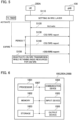
- FIG. 3 is a functional block diagram of the gNB 100. As shown in FIG. 3 , the gNB 100 includes a transmitting unit 110, a receiving unit 120, and a controlling unit 130.
- the transmitting unit 110 transmits a DL signal according to the NR system.
- the DL signal transmitted by the transmitting unit 110 includes a physical layer (PHY) signal (radio signal) and a radio resource control layer (RR C) signal.
- PHY physical layer
- RR C radio resource control layer
- the receiving unit 120 receives the UL signal according to the NR system. Similar to the transmitting unit 110, the UL signal received by the receiving unit 120 includes a physical layer (PHY) signal (radio signal), a radio resource control layer (RRC) signal, and a non-access stratum (NAS) signal.
- PHY physical layer
- RRC radio resource control layer
- NAS non-access stratum
- the receiving unit 120 receives from the UE 200A ( UE 200B) the CSI and / or the SRS by using predetermined radio resources (such as frequency, time, and space) by the Semi-Persistent transmission method. Similar to the UE 200A, the gNB 100 supports the plurality of the transmission methods including the Semi-Persistent method. Specifically, the receiving unit 120 can receive the CSI and the SRS transmitted from the UE 200A by using any of the "Periodic", “Aperiodic", and " Semi-Persistent" transmission methods.
- the controlling unit 130 performs control relating to the DL signals transmitted by the transmitting unit 110 and the UL signals received by the receiving unit 120.
- the controlling unit 130 retains the radio resources for the CSI / SRS transmission performed by the UE 200A.
- the controlling unit 130 does not release but retains the radio resources for the CSI / SRS transmission.
- the controlling unit 130 does not release but retains the radio resources for the CSI / SRS transmission.
- Operation of Radio Communication System Operation of the radio communication system 10 is explained below. Specifically, an operation in which the gNB 100 and the UE 200A transmit the CSI or the SRS is explained.
- FIG. 4 a sequence in which the transmission of the CSI or the SRS is performed by the gNB 100 and the UE 200A ( part 1) is shown.
- the Semi-Persistent transmission method is configured as the transmission method of the CSI / SRS.
- the gNB 100 and the UE 200A perform settings in the RRClayer ( Step S10). Accordingly, the transmitting and receiving the CSI / SRS becomes possible.
- the gNB 100 transmits to the UE 200A a command (Activate) via which the CSI / SRS transmission in the Semi-Persistent is activated (Step S20).
- the UE 200A transmits the CSI / SRS for every period T ( Steps S30 to S50).
- CSI / SRS indicates the CSI and / or SRS (represented as CSI / SRS report in the figures) .
- FIG. 5 a sequence in which the transmission of the CSI or the SRS is performed by the gNB 100 and the UE 200A ( part 2) is shown. Even in the present operation example, "Semi-Persistent" is configured as the transmission method of the CSI / SRS. Apart of the operations that is different from that performed in Operation Example 1 will be mainly explained below.
- the UE 200A activates the time Alignment Timer (TA timer in the figure).
- the UE 200A transmits the CSI / SRS in each period T ( Steps S130 and S140). Moreover, the time Alignment Timer (TA timer) expires after the CSI / SRS is transmitted at Step S130.
- the UE 200A deactivates the CSI / SRS transmission while retaining the radio resources for the CSI / SRS transmission (Step S150).
- the UE 200A (the same applies to the UE 200B, hereinafter the same) retains the radio resources for the CSI / SRS transmission, and deactivates the CSI / SRS transmission.
- the gNB 100 retains the radio resources for the CSI / SRS transmission.
- the radio resources for the CSI / SRS transmission are retained, it is not necessary to reconfigure the radio resources in the RRC even when the UE 200A completes the random access procedure and returns to the previous state.
- the radio resources used for the Semi-Persistent method can be used commonly between the plurality of the UEs, even when the radio resources are retained, utilization efficiency of the radio resources is not adversely affected.
- one of the aims of using the Semi-Persistent method is to essentially avoid reconfiguration of the radio resources in the RRC, according to the present embodiment, even when the timeAlignmentTimer expires, such reconfiguration can be reliably avoided.
- the UE 200A when the time Alignment Timer is restarted, the UE 200A can activate (resume) the transmission of the CSI / SRS. Therefore, transmission of the CSI / SRS can be promptly resumed by using the retained radio resources for the CSI / SRS transmission. Accordingly, a more efficient utilization of the radio resources for the CSI and the SRS can be realized.
- the UE 200Acan performs different control in the control ( handling) to be performed when the time Alignment Timer for the CSI expires and the control to be performed when the timeAlignmentTimer for the SRS expires. Therefore, it is possible to realize an appropriate handling of the radio resources according to the characteristics of the CSI and the SRS or the amount of the radio resources that can be secured within a cell.
- the UE 200A when the carrier based SRS switching is applied, the UE 200A can performs different control in a control to be performed when the time Alignment Timer for the SRS to which the carrier based SRS switching is applied expires, and a control to be performed when the time Alignment Timer for the SRS to which the carrier based SRS switching is not applied expires. Therefore, an appropriate handling of the radio resource according to the characteristics of the carrier based SRS switching can be realized.
- a control (handling) to be performed when the time Alignment Timer for the CSI expires and a control (handling) to be performed when the time Alignment Timer for the SRS expires can be different for each component carrier (CC) (specifically, for P Cell (Primary Cell), PS Cell (Primary S Cell) PUCCH S Cell (Secondary Cell), or a normal S Cell) .
- CC component carrier
- such a handling can be different depending on the UL type (Supplemental UL) and Normal UL (non-SUL), or can be different for each BWP (Bandwidth part) (initial BWP, default BWP, or other BWP).
- the handling for the CSI and the handling for the SRS can differ in the attributes explained above.
- the PUCCH and SRS used for CSI transmission are explained as an example, however, a similar control can be applied to other channels (for example, PUSCH (Physical Uplink Shared Channel)) to which the similar control can be applied.
- PUSCH Physical Uplink Shared Channel
- each functional block may be realized by one device combined physically and / or logically.
- two or more devices separated physically and / or logically may be directly and / or indirectly connected (for example, wired and / or wireless) to each other, and each functional block may be realized by these plural devices.
- FIG. 6 is a diagram showing an example of a hardware configuration of these devices. As shown in FIG. 6 , these devices can be configured as a computer device including a processor 1001, a memory 1002, a storage 1003, a communication device 1004, an input device 1005, an output device 1006, a bus 1007, and the like.
- the processor 1001 for example, operates an operating system to control the entire computer.
- the processor 1001 can be configured with a central processing unit ( CPU) including an interface with a peripheral device, a control device, a computing device, a register, and the like.
- CPU central processing unit
- the memory 1002 is a computer readable recording medium and is configured, for example, with at least one of ROM (Read Only Memory), EPROM ( Erasable Programmable ROM), EEPROM (Electrically Erasable Programmable ROM), RAM (Random Access Memory), and the like.
- the memory 1002 can be called register, cache, main memory (main memory), and the like.
- the memory 1002 can store therein a computer program (computer program codes), software modules, and the like that can execute the method according to the above embodiments.
- the storage 1003 is a computer readable recording medium.
- Examples of the storage 1003 include an optical disk such as CD-ROM ( Compact Disc ROM), a hard disk drive, a flexible disk, a magneto-optical disk (for example, a compact disk, a digital versatile disk, a Blu-ray ( Registered Trademark) disk), a smart card, a flash memory (for example, a card, a stick, a key drive), a floppy (Registered Trademark) disk, a magnetic strip, and the like.
- the storage 1003 can be called an auxiliary storage device.
- the recording medium can be, for example, a database including the memory 1002 and / or the storage 1003, a server, or other appropriate medium.
- the communication device 1004 is hardware (transmission / reception device) capable of performing communication between computers via a wired and / or wireless network.
- the communication device 1004 is also called, for example, a network device, a network controller, a network card, a communication module, and the like.
- the input device 1005 is an input device (for example, a keyboard, a mouse, a microphone, a switch, a button, a sensor, and the like) that accepts input from the outside.
- the output device 1006 is an output device (for example, a display, a speaker, an LED lamp, and the like) that outputs data to the outside. Note that, the input device 1005 and the output device 1006 may be integrated (for example, a touch screen).
- the respective devices such as the processor 1001 and the memory 1002, are connected to each other with the bus 1007 for communicating information there among.
- the bus 1007 can be constituted by a single bus or can be constituted by separate buses between the devices.
- the manner of notification of information is not limited to the one explained in the embodiments, and the notification may be performed in other manner.
- the notification of information can be performed by physical layer signaling (for example, DCI (Downlink Control Information), UCI (Uplink Control Information)), upper layer signaling (for example, RRC signaling, MAC ( Medium Access Control) signaling, notification information (MIB (Master Information Block), SIB (System Information Block)), other signals, or a combination thereof.
- the RRC signaling can be called RRC message, and the RRC signaling can be, for example, RRC Connection Setup message, RRC Connection Reconfiguration message, and the like.
- the input / output information can be stored in a specific location (for example, a memory) or can be managed in a management table.
- the information to be input / output can be overwritten, updated, or added.
- the information can be deleted after outputting.
- the inputted information can be transmitted to another device.
- the specific operations performed by the gNB 100 can be performed by another network node (device).
- functions of the gNB 100 can be provided by combining a plurality of other network nodes.
- the used parameter and the like can be represented by an absolute value, can be expressed as a relative value from a predetermined value, or can be represented by corresponding other information.
- the radio resource can be indicated by an index.
- the gNB 100 can accommodate one or more (for example, three) cells (also called sectors).
- the entire coverage area of the base station can be divided into a plurality of smaller areas.
- communication service can be provided by a base station subsystem (for example, a small base station for indoor use RRH: Remote Radio Head).
- cell refers to a part or all of the coverage area of a base station and / or a base station subsystem that performs communication service in this coverage.
- base station eNB
- cell refers to a part or all of the coverage area of a base station and / or a base station subsystem that performs communication service in this coverage.
- base station eNB
- cell refers to a part or all of the coverage area of a base station and / or a base station subsystem that performs communication service in this coverage.
- base station eNodeB
- gNB gNodeB
- the UE 200Aand the UE 200B are called by the persons skilled in the art as a subscriber station, a mobile unit, a subscriber unit, a radio unit, a remote unit, a mobile device, a radio device, a radio communication device, a remote device, a mobile subscriber station, an access terminal, a mobile terminal, a radio terminal, a remote terminal, a handset, a user agent, a mobile client, a client, or with some other suitable term.
- the phrase “based on” does not mean “based only on” unless explicitly stated otherwise. In other words, the phrase “based on” means both “based only on” and “based at least on”.
- any reference to an element using a designation such as "first”, “second”, and the like used in the present specification generally does not limit the amount or order of those elements. Such designations can be used in the present specification as a convenient way to distinguish between two or more elements. Thus, the reference to the first and second elements does not imply that only two elements can be adopted, or that the first element must precede the second element in some or the other manner.
- the present invention is useful in that, a more efficient utilization of the radio resources for the CSI and the SRS can be realized.
Landscapes
- Engineering & Computer Science (AREA)
- Signal Processing (AREA)
- Computer Networks & Wireless Communication (AREA)
- Mobile Radio Communication Systems (AREA)
Claims (4)
- Endgerät (200), umfassend:eine Sendeeinheit (210), die konfiguriert ist, um Kanalzustandsinformationen und/oder ein Referenzsignal an eine Funkbasisstation (100) unter Verwendung vorbestimmter Funkressourcen nach dem Verfahren der semipersistenten Übertragung zu senden; undeine Steuereinheit (230), die konfiguriert ist, um die vorbestimmten Funkressourcen beizubehalten und die von der Sendeeinheit (210) durchgeführte Übertragung zu deaktivieren, wenn ein Zeitausrichtungszeitgeber einer Uplink-Übertragung abläuft,wobei die Steuereinheit (230) konfiguriert ist, um, wenn der Zeitausrichtungszeitgeber abläuft, die von der Sendeeinheit durchgeführte Übertragung der Kanalzustandsinformationen zu deaktivieren und das Referenzsignal anders als eine Steuerung der Kanalzustandsinformationen zu steuern.
- Endgerät (200) nach Anspruch 1, wobei die Steuereinheit (230) konfiguriert ist, um die von der Sendeeinheit durchgeführte Übertragung zu aktivieren, wenn der Zeitausrichtungszeitgeber neu gestartet wird.
- Endgerät (200) nach Anspruch 1, wobei die Steuereinheit (230) konfiguriert ist, um, wenn die trägerbasierte SRS-Umschaltung angewendet wird, eine unterschiedliche Steuerung durchzuführen, und zwar eine Steuerung, die durchgeführt wird, wenn der Zeitausrichtungszeitgeber für das Referenzsignal, auf das die Umschaltung angewendet wird, abläuft, und eine Steuerung, die durchgeführt wird, wenn der Zeitausrichtungszeitgeber für das Referenzsignal, auf das die Umschaltung nicht angewendet wird, abläuft.
- Funkbasisstation (100), umfassend:eine Empfangseinheit (120), die konfiguriert ist, um von einem Endgerät (200) Kanalzustandsinformationen und/oder ein Referenzsignal zu empfangen, das unter Verwendung vorbestimmter Funkressourcen nach dem Verfahren der semipersistenten Übertragung gesendet wird; undeine Steuereinheit (130), die konfiguriert ist, um die vorbestimmten Funkressourcen auch dann beizubehalten, wenn ein Zeitausrichtungszeitgeber einer Aufwärtsübertragung in dem Endgerät abläuft.
Applications Claiming Priority (1)
| Application Number | Priority Date | Filing Date | Title |
|---|---|---|---|
| PCT/JP2018/014635 WO2019193725A1 (ja) | 2018-04-05 | 2018-04-05 | ユーザ装置及び無線基地局 |
Publications (3)
| Publication Number | Publication Date |
|---|---|
| EP3780801A1 EP3780801A1 (de) | 2021-02-17 |
| EP3780801A4 EP3780801A4 (de) | 2021-12-08 |
| EP3780801B1 true EP3780801B1 (de) | 2024-07-17 |
Family
ID=68100375
Family Applications (1)
| Application Number | Title | Priority Date | Filing Date |
|---|---|---|---|
| EP18913942.1A Active EP3780801B1 (de) | 2018-04-05 | 2018-04-05 | Benutzervorrichtung und drahtlose basisstation |
Country Status (6)
| Country | Link |
|---|---|
| US (1) | US20210153192A1 (de) |
| EP (1) | EP3780801B1 (de) |
| JP (1) | JP7273801B2 (de) |
| CN (1) | CN111937454B (de) |
| PL (1) | PL3780801T3 (de) |
| WO (1) | WO2019193725A1 (de) |
Families Citing this family (1)
| Publication number | Priority date | Publication date | Assignee | Title |
|---|---|---|---|---|
| EP3777386B1 (de) * | 2018-05-10 | 2023-01-25 | Apple Inc. | Zellulare meldungstechniken für synchronisationsstatusänderungen |
Family Cites Families (18)
| Publication number | Priority date | Publication date | Assignee | Title |
|---|---|---|---|---|
| SG194059A1 (en) * | 2011-04-01 | 2013-11-29 | Interdigital Patent Holdings | Method and apparatus for controlling connectivity to a network |
| JP2013102398A (ja) * | 2011-11-09 | 2013-05-23 | Ntt Docomo Inc | 無線通信システム、ユーザ端末及び無線通信方法 |
| EP3937551A3 (de) * | 2012-01-25 | 2022-02-09 | Comcast Cable Communications, LLC | Direktzugriffskanal in einer drahtlosen mehrträgerkommunikation mit zeitvorlaufsgruppen |
| JP5743965B2 (ja) * | 2012-06-26 | 2015-07-01 | 株式会社Nttドコモ | ユーザ端末、無線通信システム、無線通信方法及び無線基地局 |
| US8976780B2 (en) * | 2012-09-27 | 2015-03-10 | Blackberry Limited | Uplink timing maintenance upon time alignment timer expiry |
| WO2015151729A1 (ja) * | 2014-03-31 | 2015-10-08 | 株式会社Nttドコモ | 移動局、基地局、上りリンク信号送信方法及び上りリンク信号受信方法 |
| JP2016034112A (ja) * | 2014-07-31 | 2016-03-10 | 株式会社Nttドコモ | ユーザ装置、及び上り送信タイミング制御方法 |
| EP3070986B1 (de) * | 2015-02-26 | 2019-05-08 | HTC Corporation | Vorrichtung und verfahren zur handhabung von kommunikationsoperationen mit einem netzwerk |
| US9992759B2 (en) * | 2015-03-09 | 2018-06-05 | Ofinno Technologies, Llc | Downlink multicast channel and data channel in a wireless network |
| CN107534540B (zh) * | 2015-04-10 | 2020-10-23 | Lg 电子株式会社 | 在无线通信系统中报告信道状态信息的方法及其设备 |
| CN107431522B (zh) * | 2015-04-10 | 2021-03-16 | Lg 电子株式会社 | 在无线通信系统中报告信道状态信息的方法及其设备 |
| US10123349B2 (en) * | 2015-07-09 | 2018-11-06 | Qualcomm Incorporated | Low latency physical uplink control channel with scheduling request and channel state information |
| CN108029088B (zh) * | 2015-09-18 | 2021-01-15 | 夏普株式会社 | 终端装置、基站装置以及通信方法 |
| EP4294094B1 (de) * | 2016-08-10 | 2025-05-14 | InterDigital Patent Holdings, Inc. | Lichtkonnektivität und autonome mobilität |
| WO2018043560A1 (ja) * | 2016-08-31 | 2018-03-08 | 株式会社Nttドコモ | ユーザ端末及び無線通信方法 |
| US10512036B2 (en) * | 2017-03-22 | 2019-12-17 | Ofinno, Llc | Secondary base station change |
| KR102580213B1 (ko) * | 2017-06-15 | 2023-09-19 | 삼성전자주식회사 | 이동 통신 시스템에서의 데이터 전송 방법 및 장치 |
| CA3024549A1 (en) * | 2017-11-16 | 2019-05-16 | Comcast Cable Communications, Llc | Power control for bandwidth part switching |
-
2018
- 2018-04-05 EP EP18913942.1A patent/EP3780801B1/de active Active
- 2018-04-05 WO PCT/JP2018/014635 patent/WO2019193725A1/ja not_active Ceased
- 2018-04-05 PL PL18913942.1T patent/PL3780801T3/pl unknown
- 2018-04-05 JP JP2020512192A patent/JP7273801B2/ja active Active
- 2018-04-05 CN CN201880092119.2A patent/CN111937454B/zh active Active
- 2018-04-05 US US17/045,082 patent/US20210153192A1/en not_active Abandoned
Also Published As
| Publication number | Publication date |
|---|---|
| CN111937454B (zh) | 2024-03-01 |
| EP3780801A4 (de) | 2021-12-08 |
| WO2019193725A1 (ja) | 2019-10-10 |
| US20210153192A1 (en) | 2021-05-20 |
| CN111937454A (zh) | 2020-11-13 |
| EP3780801A1 (de) | 2021-02-17 |
| JP7273801B2 (ja) | 2023-05-15 |
| JPWO2019193725A1 (ja) | 2021-04-15 |
| PL3780801T3 (pl) | 2024-11-12 |
Similar Documents
| Publication | Publication Date | Title |
|---|---|---|
| US12531622B2 (en) | Enhancements for beam group reporting in multi-TRP scenarios | |
| US12150169B2 (en) | Random-access procedure | |
| CN111434182B (zh) | 用户装置 | |
| EP3909180B1 (de) | Scell-verwaltung für ca | |
| US20210266849A1 (en) | User equipment | |
| US20230309165A1 (en) | User terminal, base station, and radio communication method | |
| JPWO2018143353A1 (ja) | ユーザ装置及び無線通信方法 | |
| US20190021060A1 (en) | Radio base station and communication control method | |
| EP3780801B1 (de) | Benutzervorrichtung und drahtlose basisstation | |
| US20190110275A1 (en) | Radio base station and communication control method | |
| JP7149324B2 (ja) | 端末及び基地局装置 | |
| JP7108026B2 (ja) | ユーザ装置及び無線基地局 | |
| WO2026018818A1 (en) | Methods and apparatuses for on-demand synchronization signal block operations in wireless communication systems | |
| JP7100195B2 (ja) | ユーザ装置 | |
| KR20250042037A (ko) | 무선 통신 시스템에서 핸드오버 절차를 수행하는 방법 및 장치 | |
| HK40013424A (en) | Methods and devices for random access procedure | |
| HK40013424B (en) | Methods and devices for random access procedure |
Legal Events
| Date | Code | Title | Description |
|---|---|---|---|
| STAA | Information on the status of an ep patent application or granted ep patent |
Free format text: STATUS: THE INTERNATIONAL PUBLICATION HAS BEEN MADE |
|
| PUAI | Public reference made under article 153(3) epc to a published international application that has entered the european phase |
Free format text: ORIGINAL CODE: 0009012 |
|
| STAA | Information on the status of an ep patent application or granted ep patent |
Free format text: STATUS: REQUEST FOR EXAMINATION WAS MADE |
|
| 17P | Request for examination filed |
Effective date: 20201020 |
|
| AK | Designated contracting states |
Kind code of ref document: A1 Designated state(s): AL AT BE BG CH CY CZ DE DK EE ES FI FR GB GR HR HU IE IS IT LI LT LU LV MC MK MT NL NO PL PT RO RS SE SI SK SM TR |
|
| AX | Request for extension of the european patent |
Extension state: BA ME |
|
| DAV | Request for validation of the european patent (deleted) | ||
| DAX | Request for extension of the european patent (deleted) | ||
| A4 | Supplementary search report drawn up and despatched |
Effective date: 20211108 |
|
| RIC1 | Information provided on ipc code assigned before grant |
Ipc: H04L 5/00 20060101ALI20211102BHEP Ipc: H04W 72/04 20090101AFI20211102BHEP |
|
| P01 | Opt-out of the competence of the unified patent court (upc) registered |
Effective date: 20230509 |
|
| RIC1 | Information provided on ipc code assigned before grant |
Ipc: H04L 5/00 20060101ALI20231130BHEP Ipc: H04W 72/04 20090101AFI20231130BHEP |
|
| GRAP | Despatch of communication of intention to grant a patent |
Free format text: ORIGINAL CODE: EPIDOSNIGR1 |
|
| STAA | Information on the status of an ep patent application or granted ep patent |
Free format text: STATUS: GRANT OF PATENT IS INTENDED |
|
| INTG | Intention to grant announced |
Effective date: 20240227 |
|
| GRAS | Grant fee paid |
Free format text: ORIGINAL CODE: EPIDOSNIGR3 |
|
| GRAA | (expected) grant |
Free format text: ORIGINAL CODE: 0009210 |
|
| STAA | Information on the status of an ep patent application or granted ep patent |
Free format text: STATUS: THE PATENT HAS BEEN GRANTED |
|
| AK | Designated contracting states |
Kind code of ref document: B1 Designated state(s): AL AT BE BG CH CY CZ DE DK EE ES FI FR GB GR HR HU IE IS IT LI LT LU LV MC MK MT NL NO PL PT RO RS SE SI SK SM TR |
|
| REG | Reference to a national code |
Ref country code: CH Ref legal event code: EP |
|
| REG | Reference to a national code |
Ref country code: DE Ref legal event code: R096 Ref document number: 602018072035 Country of ref document: DE |
|
| REG | Reference to a national code |
Ref country code: IE Ref legal event code: FG4D |
|
| REG | Reference to a national code |
Ref country code: LT Ref legal event code: MG9D |
|
| REG | Reference to a national code |
Ref country code: NL Ref legal event code: MP Effective date: 20240717 |
|
| PG25 | Lapsed in a contracting state [announced via postgrant information from national office to epo] |
Ref country code: PT Free format text: LAPSE BECAUSE OF FAILURE TO SUBMIT A TRANSLATION OF THE DESCRIPTION OR TO PAY THE FEE WITHIN THE PRESCRIBED TIME-LIMIT Effective date: 20241118 |
|
| REG | Reference to a national code |
Ref country code: AT Ref legal event code: MK05 Ref document number: 1705291 Country of ref document: AT Kind code of ref document: T Effective date: 20240717 |
|
| PG25 | Lapsed in a contracting state [announced via postgrant information from national office to epo] |
Ref country code: NL Free format text: LAPSE BECAUSE OF FAILURE TO SUBMIT A TRANSLATION OF THE DESCRIPTION OR TO PAY THE FEE WITHIN THE PRESCRIBED TIME-LIMIT Effective date: 20240717 |
|
| PG25 | Lapsed in a contracting state [announced via postgrant information from national office to epo] |
Ref country code: PT Free format text: LAPSE BECAUSE OF FAILURE TO SUBMIT A TRANSLATION OF THE DESCRIPTION OR TO PAY THE FEE WITHIN THE PRESCRIBED TIME-LIMIT Effective date: 20241118 Ref country code: NL Free format text: LAPSE BECAUSE OF FAILURE TO SUBMIT A TRANSLATION OF THE DESCRIPTION OR TO PAY THE FEE WITHIN THE PRESCRIBED TIME-LIMIT Effective date: 20240717 |
|
| PG25 | Lapsed in a contracting state [announced via postgrant information from national office to epo] |
Ref country code: NO Free format text: LAPSE BECAUSE OF FAILURE TO SUBMIT A TRANSLATION OF THE DESCRIPTION OR TO PAY THE FEE WITHIN THE PRESCRIBED TIME-LIMIT Effective date: 20241017 |
|
| PG25 | Lapsed in a contracting state [announced via postgrant information from national office to epo] |
Ref country code: FI Free format text: LAPSE BECAUSE OF FAILURE TO SUBMIT A TRANSLATION OF THE DESCRIPTION OR TO PAY THE FEE WITHIN THE PRESCRIBED TIME-LIMIT Effective date: 20240717 Ref country code: GR Free format text: LAPSE BECAUSE OF FAILURE TO SUBMIT A TRANSLATION OF THE DESCRIPTION OR TO PAY THE FEE WITHIN THE PRESCRIBED TIME-LIMIT Effective date: 20241018 |
|
| PG25 | Lapsed in a contracting state [announced via postgrant information from national office to epo] |
Ref country code: BG Free format text: LAPSE BECAUSE OF FAILURE TO SUBMIT A TRANSLATION OF THE DESCRIPTION OR TO PAY THE FEE WITHIN THE PRESCRIBED TIME-LIMIT Effective date: 20240717 |
|
| PG25 | Lapsed in a contracting state [announced via postgrant information from national office to epo] |
Ref country code: LV Free format text: LAPSE BECAUSE OF FAILURE TO SUBMIT A TRANSLATION OF THE DESCRIPTION OR TO PAY THE FEE WITHIN THE PRESCRIBED TIME-LIMIT Effective date: 20240717 |
|
| PG25 | Lapsed in a contracting state [announced via postgrant information from national office to epo] |
Ref country code: IS Free format text: LAPSE BECAUSE OF FAILURE TO SUBMIT A TRANSLATION OF THE DESCRIPTION OR TO PAY THE FEE WITHIN THE PRESCRIBED TIME-LIMIT Effective date: 20241117 Ref country code: AT Free format text: LAPSE BECAUSE OF FAILURE TO SUBMIT A TRANSLATION OF THE DESCRIPTION OR TO PAY THE FEE WITHIN THE PRESCRIBED TIME-LIMIT Effective date: 20240717 |
|
| PG25 | Lapsed in a contracting state [announced via postgrant information from national office to epo] |
Ref country code: HR Free format text: LAPSE BECAUSE OF FAILURE TO SUBMIT A TRANSLATION OF THE DESCRIPTION OR TO PAY THE FEE WITHIN THE PRESCRIBED TIME-LIMIT Effective date: 20240717 |
|
| PG25 | Lapsed in a contracting state [announced via postgrant information from national office to epo] |
Ref country code: ES Free format text: LAPSE BECAUSE OF FAILURE TO SUBMIT A TRANSLATION OF THE DESCRIPTION OR TO PAY THE FEE WITHIN THE PRESCRIBED TIME-LIMIT Effective date: 20240717 Ref country code: RS Free format text: LAPSE BECAUSE OF FAILURE TO SUBMIT A TRANSLATION OF THE DESCRIPTION OR TO PAY THE FEE WITHIN THE PRESCRIBED TIME-LIMIT Effective date: 20241017 |
|
| PG25 | Lapsed in a contracting state [announced via postgrant information from national office to epo] |
Ref country code: RS Free format text: LAPSE BECAUSE OF FAILURE TO SUBMIT A TRANSLATION OF THE DESCRIPTION OR TO PAY THE FEE WITHIN THE PRESCRIBED TIME-LIMIT Effective date: 20241017 Ref country code: NO Free format text: LAPSE BECAUSE OF FAILURE TO SUBMIT A TRANSLATION OF THE DESCRIPTION OR TO PAY THE FEE WITHIN THE PRESCRIBED TIME-LIMIT Effective date: 20241017 Ref country code: LV Free format text: LAPSE BECAUSE OF FAILURE TO SUBMIT A TRANSLATION OF THE DESCRIPTION OR TO PAY THE FEE WITHIN THE PRESCRIBED TIME-LIMIT Effective date: 20240717 Ref country code: IS Free format text: LAPSE BECAUSE OF FAILURE TO SUBMIT A TRANSLATION OF THE DESCRIPTION OR TO PAY THE FEE WITHIN THE PRESCRIBED TIME-LIMIT Effective date: 20241117 Ref country code: HR Free format text: LAPSE BECAUSE OF FAILURE TO SUBMIT A TRANSLATION OF THE DESCRIPTION OR TO PAY THE FEE WITHIN THE PRESCRIBED TIME-LIMIT Effective date: 20240717 Ref country code: GR Free format text: LAPSE BECAUSE OF FAILURE TO SUBMIT A TRANSLATION OF THE DESCRIPTION OR TO PAY THE FEE WITHIN THE PRESCRIBED TIME-LIMIT Effective date: 20241018 Ref country code: FI Free format text: LAPSE BECAUSE OF FAILURE TO SUBMIT A TRANSLATION OF THE DESCRIPTION OR TO PAY THE FEE WITHIN THE PRESCRIBED TIME-LIMIT Effective date: 20240717 Ref country code: ES Free format text: LAPSE BECAUSE OF FAILURE TO SUBMIT A TRANSLATION OF THE DESCRIPTION OR TO PAY THE FEE WITHIN THE PRESCRIBED TIME-LIMIT Effective date: 20240717 Ref country code: BG Free format text: LAPSE BECAUSE OF FAILURE TO SUBMIT A TRANSLATION OF THE DESCRIPTION OR TO PAY THE FEE WITHIN THE PRESCRIBED TIME-LIMIT Effective date: 20240717 Ref country code: AT Free format text: LAPSE BECAUSE OF FAILURE TO SUBMIT A TRANSLATION OF THE DESCRIPTION OR TO PAY THE FEE WITHIN THE PRESCRIBED TIME-LIMIT Effective date: 20240717 |
|
| PG25 | Lapsed in a contracting state [announced via postgrant information from national office to epo] |
Ref country code: DK Free format text: LAPSE BECAUSE OF FAILURE TO SUBMIT A TRANSLATION OF THE DESCRIPTION OR TO PAY THE FEE WITHIN THE PRESCRIBED TIME-LIMIT Effective date: 20240717 Ref country code: RO Free format text: LAPSE BECAUSE OF FAILURE TO SUBMIT A TRANSLATION OF THE DESCRIPTION OR TO PAY THE FEE WITHIN THE PRESCRIBED TIME-LIMIT Effective date: 20240717 Ref country code: SM Free format text: LAPSE BECAUSE OF FAILURE TO SUBMIT A TRANSLATION OF THE DESCRIPTION OR TO PAY THE FEE WITHIN THE PRESCRIBED TIME-LIMIT Effective date: 20240717 |
|
| REG | Reference to a national code |
Ref country code: DE Ref legal event code: R097 Ref document number: 602018072035 Country of ref document: DE |
|
| PG25 | Lapsed in a contracting state [announced via postgrant information from national office to epo] |
Ref country code: EE Free format text: LAPSE BECAUSE OF FAILURE TO SUBMIT A TRANSLATION OF THE DESCRIPTION OR TO PAY THE FEE WITHIN THE PRESCRIBED TIME-LIMIT Effective date: 20240717 |
|
| PG25 | Lapsed in a contracting state [announced via postgrant information from national office to epo] |
Ref country code: CZ Free format text: LAPSE BECAUSE OF FAILURE TO SUBMIT A TRANSLATION OF THE DESCRIPTION OR TO PAY THE FEE WITHIN THE PRESCRIBED TIME-LIMIT Effective date: 20240717 |
|
| PGFP | Annual fee paid to national office [announced via postgrant information from national office to epo] |
Ref country code: PL Payment date: 20250321 Year of fee payment: 8 |
|
| PG25 | Lapsed in a contracting state [announced via postgrant information from national office to epo] |
Ref country code: SK Free format text: LAPSE BECAUSE OF FAILURE TO SUBMIT A TRANSLATION OF THE DESCRIPTION OR TO PAY THE FEE WITHIN THE PRESCRIBED TIME-LIMIT Effective date: 20240717 |
|
| PLBE | No opposition filed within time limit |
Free format text: ORIGINAL CODE: 0009261 |
|
| STAA | Information on the status of an ep patent application or granted ep patent |
Free format text: STATUS: NO OPPOSITION FILED WITHIN TIME LIMIT |
|
| 26N | No opposition filed |
Effective date: 20250422 |
|
| PGFP | Annual fee paid to national office [announced via postgrant information from national office to epo] |
Ref country code: DE Payment date: 20250422 Year of fee payment: 8 |
|
| PGFP | Annual fee paid to national office [announced via postgrant information from national office to epo] |
Ref country code: GB Payment date: 20250423 Year of fee payment: 8 |
|
| PG25 | Lapsed in a contracting state [announced via postgrant information from national office to epo] |
Ref country code: SE Free format text: LAPSE BECAUSE OF FAILURE TO SUBMIT A TRANSLATION OF THE DESCRIPTION OR TO PAY THE FEE WITHIN THE PRESCRIBED TIME-LIMIT Effective date: 20240717 |
|
| REG | Reference to a national code |
Ref country code: CH Ref legal event code: H13 Free format text: ST27 STATUS EVENT CODE: U-0-0-H10-H13 (AS PROVIDED BY THE NATIONAL OFFICE) Effective date: 20251125 |
|
| PG25 | Lapsed in a contracting state [announced via postgrant information from national office to epo] |
Ref country code: LU Free format text: LAPSE BECAUSE OF NON-PAYMENT OF DUE FEES Effective date: 20250405 |
|
| PG25 | Lapsed in a contracting state [announced via postgrant information from national office to epo] |
Ref country code: MC Free format text: LAPSE BECAUSE OF FAILURE TO SUBMIT A TRANSLATION OF THE DESCRIPTION OR TO PAY THE FEE WITHIN THE PRESCRIBED TIME-LIMIT Effective date: 20240717 |
|
| REG | Reference to a national code |
Ref country code: BE Ref legal event code: MM Effective date: 20250430 |
|
| PG25 | Lapsed in a contracting state [announced via postgrant information from national office to epo] |
Ref country code: FR Free format text: LAPSE BECAUSE OF NON-PAYMENT OF DUE FEES Effective date: 20250430 |
|
| PG25 | Lapsed in a contracting state [announced via postgrant information from national office to epo] |
Ref country code: BE Free format text: LAPSE BECAUSE OF NON-PAYMENT OF DUE FEES Effective date: 20250430 |
|
| PG25 | Lapsed in a contracting state [announced via postgrant information from national office to epo] |
Ref country code: CH Free format text: LAPSE BECAUSE OF NON-PAYMENT OF DUE FEES Effective date: 20250430 |