EP3780250B1 - Batteriemodul, batteriepack mit solch einem batteriemodul und fahrzeug mit solch einem batteriepack - Google Patents
Batteriemodul, batteriepack mit solch einem batteriemodul und fahrzeug mit solch einem batteriepack Download PDFInfo
- Publication number
- EP3780250B1 EP3780250B1 EP19860960.4A EP19860960A EP3780250B1 EP 3780250 B1 EP3780250 B1 EP 3780250B1 EP 19860960 A EP19860960 A EP 19860960A EP 3780250 B1 EP3780250 B1 EP 3780250B1
- Authority
- EP
- European Patent Office
- Prior art keywords
- bus bar
- heatsink
- battery
- battery module
- battery cell
- Prior art date
- Legal status (The legal status is an assumption and is not a legal conclusion. Google has not performed a legal analysis and makes no representation as to the accuracy of the status listed.)
- Active
Links
- 238000001816 cooling Methods 0.000 claims description 59
- 239000000498 cooling water Substances 0.000 claims description 54
- 239000000463 material Substances 0.000 claims description 3
- 238000010586 diagram Methods 0.000 description 22
- 230000020169 heat generation Effects 0.000 description 3
- 230000001965 increasing effect Effects 0.000 description 3
- PXHVJJICTQNCMI-UHFFFAOYSA-N Nickel Chemical compound [Ni] PXHVJJICTQNCMI-UHFFFAOYSA-N 0.000 description 2
- 239000000446 fuel Substances 0.000 description 2
- UFHFLCQGNIYNRP-UHFFFAOYSA-N Hydrogen Chemical compound [H][H] UFHFLCQGNIYNRP-UHFFFAOYSA-N 0.000 description 1
- WHXSMMKQMYFTQS-UHFFFAOYSA-N Lithium Chemical compound [Li] WHXSMMKQMYFTQS-UHFFFAOYSA-N 0.000 description 1
- HBBGRARXTFLTSG-UHFFFAOYSA-N Lithium ion Chemical compound [Li+] HBBGRARXTFLTSG-UHFFFAOYSA-N 0.000 description 1
- 239000006227 byproduct Substances 0.000 description 1
- OJIJEKBXJYRIBZ-UHFFFAOYSA-N cadmium nickel Chemical compound [Ni].[Cd] OJIJEKBXJYRIBZ-UHFFFAOYSA-N 0.000 description 1
- 230000009977 dual effect Effects 0.000 description 1
- 230000000694 effects Effects 0.000 description 1
- 238000005265 energy consumption Methods 0.000 description 1
- 238000004146 energy storage Methods 0.000 description 1
- 230000002708 enhancing effect Effects 0.000 description 1
- 239000002803 fossil fuel Substances 0.000 description 1
- 229910052739 hydrogen Inorganic materials 0.000 description 1
- 239000001257 hydrogen Substances 0.000 description 1
- 238000009413 insulation Methods 0.000 description 1
- 229910052744 lithium Inorganic materials 0.000 description 1
- 229910001416 lithium ion Inorganic materials 0.000 description 1
- 239000007769 metal material Substances 0.000 description 1
- 238000000034 method Methods 0.000 description 1
- 229910052759 nickel Inorganic materials 0.000 description 1
- QELJHCBNGDEXLD-UHFFFAOYSA-N nickel zinc Chemical compound [Ni].[Zn] QELJHCBNGDEXLD-UHFFFAOYSA-N 0.000 description 1
- 238000004806 packaging method and process Methods 0.000 description 1
- 229920000642 polymer Polymers 0.000 description 1
- 239000000047 product Substances 0.000 description 1
- 238000003466 welding Methods 0.000 description 1
Images


Classifications
-
- H—ELECTRICITY
- H01—ELECTRIC ELEMENTS
- H01M—PROCESSES OR MEANS, e.g. BATTERIES, FOR THE DIRECT CONVERSION OF CHEMICAL ENERGY INTO ELECTRICAL ENERGY
- H01M10/00—Secondary cells; Manufacture thereof
- H01M10/60—Heating or cooling; Temperature control
- H01M10/65—Means for temperature control structurally associated with the cells
- H01M10/655—Solid structures for heat exchange or heat conduction
- H01M10/6554—Rods or plates
-
- H—ELECTRICITY
- H01—ELECTRIC ELEMENTS
- H01M—PROCESSES OR MEANS, e.g. BATTERIES, FOR THE DIRECT CONVERSION OF CHEMICAL ENERGY INTO ELECTRICAL ENERGY
- H01M10/00—Secondary cells; Manufacture thereof
- H01M10/60—Heating or cooling; Temperature control
- H01M10/65—Means for temperature control structurally associated with the cells
- H01M10/655—Solid structures for heat exchange or heat conduction
-
- H—ELECTRICITY
- H01—ELECTRIC ELEMENTS
- H01M—PROCESSES OR MEANS, e.g. BATTERIES, FOR THE DIRECT CONVERSION OF CHEMICAL ENERGY INTO ELECTRICAL ENERGY
- H01M10/00—Secondary cells; Manufacture thereof
- H01M10/60—Heating or cooling; Temperature control
- H01M10/65—Means for temperature control structurally associated with the cells
- H01M10/656—Means for temperature control structurally associated with the cells characterised by the type of heat-exchange fluid
- H01M10/6567—Liquids
- H01M10/6568—Liquids characterised by flow circuits, e.g. loops, located externally to the cells or cell casings
-
- H—ELECTRICITY
- H01—ELECTRIC ELEMENTS
- H01M—PROCESSES OR MEANS, e.g. BATTERIES, FOR THE DIRECT CONVERSION OF CHEMICAL ENERGY INTO ELECTRICAL ENERGY
- H01M10/00—Secondary cells; Manufacture thereof
- H01M10/60—Heating or cooling; Temperature control
- H01M10/61—Types of temperature control
- H01M10/613—Cooling or keeping cold
-
- B—PERFORMING OPERATIONS; TRANSPORTING
- B60—VEHICLES IN GENERAL
- B60L—PROPULSION OF ELECTRICALLY-PROPELLED VEHICLES; SUPPLYING ELECTRIC POWER FOR AUXILIARY EQUIPMENT OF ELECTRICALLY-PROPELLED VEHICLES; ELECTRODYNAMIC BRAKE SYSTEMS FOR VEHICLES IN GENERAL; MAGNETIC SUSPENSION OR LEVITATION FOR VEHICLES; MONITORING OPERATING VARIABLES OF ELECTRICALLY-PROPELLED VEHICLES; ELECTRIC SAFETY DEVICES FOR ELECTRICALLY-PROPELLED VEHICLES
- B60L50/00—Electric propulsion with power supplied within the vehicle
- B60L50/50—Electric propulsion with power supplied within the vehicle using propulsion power supplied by batteries or fuel cells
- B60L50/60—Electric propulsion with power supplied within the vehicle using propulsion power supplied by batteries or fuel cells using power supplied by batteries
- B60L50/64—Constructional details of batteries specially adapted for electric vehicles
-
- B—PERFORMING OPERATIONS; TRANSPORTING
- B60—VEHICLES IN GENERAL
- B60L—PROPULSION OF ELECTRICALLY-PROPELLED VEHICLES; SUPPLYING ELECTRIC POWER FOR AUXILIARY EQUIPMENT OF ELECTRICALLY-PROPELLED VEHICLES; ELECTRODYNAMIC BRAKE SYSTEMS FOR VEHICLES IN GENERAL; MAGNETIC SUSPENSION OR LEVITATION FOR VEHICLES; MONITORING OPERATING VARIABLES OF ELECTRICALLY-PROPELLED VEHICLES; ELECTRIC SAFETY DEVICES FOR ELECTRICALLY-PROPELLED VEHICLES
- B60L58/00—Methods or circuit arrangements for monitoring or controlling batteries or fuel cells, specially adapted for electric vehicles
- B60L58/10—Methods or circuit arrangements for monitoring or controlling batteries or fuel cells, specially adapted for electric vehicles for monitoring or controlling batteries
- B60L58/24—Methods or circuit arrangements for monitoring or controlling batteries or fuel cells, specially adapted for electric vehicles for monitoring or controlling batteries for controlling the temperature of batteries
- B60L58/26—Methods or circuit arrangements for monitoring or controlling batteries or fuel cells, specially adapted for electric vehicles for monitoring or controlling batteries for controlling the temperature of batteries by cooling
-
- H—ELECTRICITY
- H01—ELECTRIC ELEMENTS
- H01M—PROCESSES OR MEANS, e.g. BATTERIES, FOR THE DIRECT CONVERSION OF CHEMICAL ENERGY INTO ELECTRICAL ENERGY
- H01M10/00—Secondary cells; Manufacture thereof
- H01M10/60—Heating or cooling; Temperature control
- H01M10/61—Types of temperature control
- H01M10/617—Types of temperature control for achieving uniformity or desired distribution of temperature
-
- H—ELECTRICITY
- H01—ELECTRIC ELEMENTS
- H01M—PROCESSES OR MEANS, e.g. BATTERIES, FOR THE DIRECT CONVERSION OF CHEMICAL ENERGY INTO ELECTRICAL ENERGY
- H01M10/00—Secondary cells; Manufacture thereof
- H01M10/60—Heating or cooling; Temperature control
- H01M10/62—Heating or cooling; Temperature control specially adapted for specific applications
- H01M10/625—Vehicles
-
- H—ELECTRICITY
- H01—ELECTRIC ELEMENTS
- H01M—PROCESSES OR MEANS, e.g. BATTERIES, FOR THE DIRECT CONVERSION OF CHEMICAL ENERGY INTO ELECTRICAL ENERGY
- H01M10/00—Secondary cells; Manufacture thereof
- H01M10/60—Heating or cooling; Temperature control
- H01M10/64—Heating or cooling; Temperature control characterised by the shape of the cells
- H01M10/647—Prismatic or flat cells, e.g. pouch cells
-
- H—ELECTRICITY
- H01—ELECTRIC ELEMENTS
- H01M—PROCESSES OR MEANS, e.g. BATTERIES, FOR THE DIRECT CONVERSION OF CHEMICAL ENERGY INTO ELECTRICAL ENERGY
- H01M10/00—Secondary cells; Manufacture thereof
- H01M10/60—Heating or cooling; Temperature control
- H01M10/65—Means for temperature control structurally associated with the cells
- H01M10/653—Means for temperature control structurally associated with the cells characterised by electrically insulating or thermally conductive materials
-
- H—ELECTRICITY
- H01—ELECTRIC ELEMENTS
- H01M—PROCESSES OR MEANS, e.g. BATTERIES, FOR THE DIRECT CONVERSION OF CHEMICAL ENERGY INTO ELECTRICAL ENERGY
- H01M10/00—Secondary cells; Manufacture thereof
- H01M10/60—Heating or cooling; Temperature control
- H01M10/65—Means for temperature control structurally associated with the cells
- H01M10/655—Solid structures for heat exchange or heat conduction
- H01M10/6551—Surfaces specially adapted for heat dissipation or radiation, e.g. fins or coatings
-
- H—ELECTRICITY
- H01—ELECTRIC ELEMENTS
- H01M—PROCESSES OR MEANS, e.g. BATTERIES, FOR THE DIRECT CONVERSION OF CHEMICAL ENERGY INTO ELECTRICAL ENERGY
- H01M10/00—Secondary cells; Manufacture thereof
- H01M10/60—Heating or cooling; Temperature control
- H01M10/65—Means for temperature control structurally associated with the cells
- H01M10/655—Solid structures for heat exchange or heat conduction
- H01M10/6553—Terminals or leads
-
- H—ELECTRICITY
- H01—ELECTRIC ELEMENTS
- H01M—PROCESSES OR MEANS, e.g. BATTERIES, FOR THE DIRECT CONVERSION OF CHEMICAL ENERGY INTO ELECTRICAL ENERGY
- H01M10/00—Secondary cells; Manufacture thereof
- H01M10/60—Heating or cooling; Temperature control
- H01M10/65—Means for temperature control structurally associated with the cells
- H01M10/655—Solid structures for heat exchange or heat conduction
- H01M10/6556—Solid parts with flow channel passages or pipes for heat exchange
-
- H—ELECTRICITY
- H01—ELECTRIC ELEMENTS
- H01M—PROCESSES OR MEANS, e.g. BATTERIES, FOR THE DIRECT CONVERSION OF CHEMICAL ENERGY INTO ELECTRICAL ENERGY
- H01M10/00—Secondary cells; Manufacture thereof
- H01M10/60—Heating or cooling; Temperature control
- H01M10/65—Means for temperature control structurally associated with the cells
- H01M10/656—Means for temperature control structurally associated with the cells characterised by the type of heat-exchange fluid
- H01M10/6567—Liquids
-
- H—ELECTRICITY
- H01—ELECTRIC ELEMENTS
- H01M—PROCESSES OR MEANS, e.g. BATTERIES, FOR THE DIRECT CONVERSION OF CHEMICAL ENERGY INTO ELECTRICAL ENERGY
- H01M50/00—Constructional details or processes of manufacture of the non-active parts of electrochemical cells other than fuel cells, e.g. hybrid cells
- H01M50/20—Mountings; Secondary casings or frames; Racks, modules or packs; Suspension devices; Shock absorbers; Transport or carrying devices; Holders
- H01M50/204—Racks, modules or packs for multiple batteries or multiple cells
- H01M50/207—Racks, modules or packs for multiple batteries or multiple cells characterised by their shape
- H01M50/211—Racks, modules or packs for multiple batteries or multiple cells characterised by their shape adapted for pouch cells
-
- H—ELECTRICITY
- H01—ELECTRIC ELEMENTS
- H01M—PROCESSES OR MEANS, e.g. BATTERIES, FOR THE DIRECT CONVERSION OF CHEMICAL ENERGY INTO ELECTRICAL ENERGY
- H01M50/00—Constructional details or processes of manufacture of the non-active parts of electrochemical cells other than fuel cells, e.g. hybrid cells
- H01M50/20—Mountings; Secondary casings or frames; Racks, modules or packs; Suspension devices; Shock absorbers; Transport or carrying devices; Holders
- H01M50/249—Mountings; Secondary casings or frames; Racks, modules or packs; Suspension devices; Shock absorbers; Transport or carrying devices; Holders specially adapted for aircraft or vehicles, e.g. cars or trains
-
- H—ELECTRICITY
- H01—ELECTRIC ELEMENTS
- H01M—PROCESSES OR MEANS, e.g. BATTERIES, FOR THE DIRECT CONVERSION OF CHEMICAL ENERGY INTO ELECTRICAL ENERGY
- H01M50/00—Constructional details or processes of manufacture of the non-active parts of electrochemical cells other than fuel cells, e.g. hybrid cells
- H01M50/20—Mountings; Secondary casings or frames; Racks, modules or packs; Suspension devices; Shock absorbers; Transport or carrying devices; Holders
- H01M50/258—Modular batteries; Casings provided with means for assembling
-
- H—ELECTRICITY
- H01—ELECTRIC ELEMENTS
- H01M—PROCESSES OR MEANS, e.g. BATTERIES, FOR THE DIRECT CONVERSION OF CHEMICAL ENERGY INTO ELECTRICAL ENERGY
- H01M50/00—Constructional details or processes of manufacture of the non-active parts of electrochemical cells other than fuel cells, e.g. hybrid cells
- H01M50/50—Current conducting connections for cells or batteries
- H01M50/502—Interconnectors for connecting terminals of adjacent batteries; Interconnectors for connecting cells outside a battery casing
- H01M50/521—Interconnectors for connecting terminals of adjacent batteries; Interconnectors for connecting cells outside a battery casing characterised by the material
- H01M50/526—Interconnectors for connecting terminals of adjacent batteries; Interconnectors for connecting cells outside a battery casing characterised by the material having a layered structure
-
- H—ELECTRICITY
- H01—ELECTRIC ELEMENTS
- H01M—PROCESSES OR MEANS, e.g. BATTERIES, FOR THE DIRECT CONVERSION OF CHEMICAL ENERGY INTO ELECTRICAL ENERGY
- H01M50/00—Constructional details or processes of manufacture of the non-active parts of electrochemical cells other than fuel cells, e.g. hybrid cells
- H01M50/50—Current conducting connections for cells or batteries
- H01M50/531—Electrode connections inside a battery casing
-
- H—ELECTRICITY
- H01—ELECTRIC ELEMENTS
- H01M—PROCESSES OR MEANS, e.g. BATTERIES, FOR THE DIRECT CONVERSION OF CHEMICAL ENERGY INTO ELECTRICAL ENERGY
- H01M50/00—Constructional details or processes of manufacture of the non-active parts of electrochemical cells other than fuel cells, e.g. hybrid cells
- H01M50/50—Current conducting connections for cells or batteries
- H01M50/543—Terminals
- H01M50/547—Terminals characterised by the disposition of the terminals on the cells
- H01M50/548—Terminals characterised by the disposition of the terminals on the cells on opposite sides of the cell
-
- H—ELECTRICITY
- H01—ELECTRIC ELEMENTS
- H01M—PROCESSES OR MEANS, e.g. BATTERIES, FOR THE DIRECT CONVERSION OF CHEMICAL ENERGY INTO ELECTRICAL ENERGY
- H01M50/00—Constructional details or processes of manufacture of the non-active parts of electrochemical cells other than fuel cells, e.g. hybrid cells
- H01M50/50—Current conducting connections for cells or batteries
- H01M50/543—Terminals
- H01M50/552—Terminals characterised by their shape
- H01M50/553—Terminals adapted for prismatic, pouch or rectangular cells
- H01M50/557—Plate-shaped terminals
-
- H—ELECTRICITY
- H01—ELECTRIC ELEMENTS
- H01M—PROCESSES OR MEANS, e.g. BATTERIES, FOR THE DIRECT CONVERSION OF CHEMICAL ENERGY INTO ELECTRICAL ENERGY
- H01M2220/00—Batteries for particular applications
- H01M2220/20—Batteries in motive systems, e.g. vehicle, ship, plane
-
- Y—GENERAL TAGGING OF NEW TECHNOLOGICAL DEVELOPMENTS; GENERAL TAGGING OF CROSS-SECTIONAL TECHNOLOGIES SPANNING OVER SEVERAL SECTIONS OF THE IPC; TECHNICAL SUBJECTS COVERED BY FORMER USPC CROSS-REFERENCE ART COLLECTIONS [XRACs] AND DIGESTS
- Y02—TECHNOLOGIES OR APPLICATIONS FOR MITIGATION OR ADAPTATION AGAINST CLIMATE CHANGE
- Y02E—REDUCTION OF GREENHOUSE GAS [GHG] EMISSIONS, RELATED TO ENERGY GENERATION, TRANSMISSION OR DISTRIBUTION
- Y02E60/00—Enabling technologies; Technologies with a potential or indirect contribution to GHG emissions mitigation
- Y02E60/10—Energy storage using batteries
Definitions
- the present disclosure relates to a battery module, a battery pack including the battery module, and a vehicle including the battery pack.
- Secondary batteries which are highly applicable to various products and exhibit superior electrical properties such as high energy density, etc. are commonly used not only in portable devices but also in electric vehicles (EVs) or hybrid electric vehicles (HEVs) driven by electrical power sources.
- EVs electric vehicles
- HEVs hybrid electric vehicles
- the secondary battery is drawing attentions as a new energy source for enhancing environment friendliness and energy efficiency in that the use of fossil fuels can be reduced greatly and no byproduct is generated during energy consumption.
- Secondary batteries widely used at present include lithium ion batteries, lithium polymer batteries, nickel cadmium batteries, nickel hydrogen batteries, nickel zinc batteries and the like.
- An operating voltage of the unit secondary battery cell namely a unit battery cell, is about 2.5V to 4.5V. Therefore, if a higher output voltage is required, a plurality of battery cells may be connected in series to configure a battery pack. In addition, depending on the charge/discharge capacity required for the battery pack, a plurality of battery cells may be connected in parallel to configure a battery pack. Thus, the number of battery cells included in the battery pack may be variously set according to the required output voltage or the demanded charge/discharge capacity.
- the temperature deviation inside the battery cell becomes large.
- a portion near the electrode lead is locally heated more than the other portion.
- JP 2013 229266 relates to an assembled battery in which a plurality of flat batteries are stacked and arranged, and particularly relates to a cooling structure of the battery.
- the present disclosure is directed to providing a battery module, which may improve a cooling temperature deviation of a battery cell when cooling a battery module or a battery pack, a battery pack including the battery module, and a vehicle including the battery pack.
- the invention provides a battery module, comprising: at least one battery cell; a bus bar assembly connected to an electrode lead of the at least one battery cell and provided to both side surfaces of the at least one battery cell; at least one heatsink provided to at least one side of the at least one battery cell and the bus bar assembly; and a pair of cooling plates connected perpendicular to the at least one heatsink and provided in direct contact with the bus bar assembly.
- the bus bar assembly may include a bus bar housing mounted to both sides of the at least one battery cell; a connection bus bar provided to the bus bar housing to contact the electrode lead of the at least one battery cell; and a heat transfer member configured to guide connection of the connection bus bar and the pair of cooling plates.
- the heat transfer member may be mounted to the connection bus bar and provided in direct contact with the connection bus bar and the pair of cooling plates, respectively.
- the heat transfer member may be made of a thermal interface material.
- the heatsink may be provided in a pair, and the pair of heatsinks may have an inner channel for a cooling water to flow and cover one side and the other side of the at least one battery cell and the bus bar assembly.
- the pair of heatsinks may include a lower heatsink configured to cover a lower side of the at least one battery cell and the bus bar assembly; and an upper heatsink disposed opposite to the lower heatsink and configured to cover an upper side of the at least one battery cell and the bus bar assembly.
- the battery module further comprises a perimeter tube configured to surround the pair of cooling plates at least partially and communicate with the at least one heatsink.
- the perimeter tube includes a tube body configured to surround each cooling plate at least partially and having an inner channel; at least one cooling water supply tube configured to communicate the tube body with the at least one heatsink and supply a cooling water to the tube body; and at least one cooling water discharge tube spaced apart from the cooling water supply tube by a predetermined distance and configured to communicate the tube body with the at least one heatsink so that the cooling water in the tube body is discharged to the at least one heatsink.
- the present disclosure provides a battery pack, comprising: at least one battery module according to the above embodiments; and a pack case configured to package the at least one battery module.
- the present disclosure provides a vehicle, comprising at least one battery pack according to the above embodiment.
- a battery module which may improve a cooling temperature deviation of a battery cell when cooling a battery module or a battery pack, a battery pack including the battery module, and a vehicle including the battery pack.
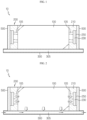
- FIG. 1 is a diagram for illustrating a battery module according to an embodiment of the present disclosure.
- the battery module 10 may include a battery cell 100, a bus bar assembly 200, a heatsink 300, and a cooling plate 500.
- the battery cell 100 is a secondary battery and may be provided as a pouch-type secondary battery, a rectangular secondary battery or a cylindrical secondary battery. Hereinafter, in this embodiment, the battery cell 100 is described as a pouch-type secondary battery.
- the battery cell 100 may be provided in at least one or more. If a plurality of battery cells 100 are provided, the plurality of battery cell 100 may be electrically connected to each other.
- the bus bar assembly 200 is connected to an electrode lead 105 of the at least one battery cell 100 and may be provided to both side surfaces of the at least one battery cell 100.
- the bus bar assembly 200 may include a bus bar housing 210, a connection bus bar 230, and a heat transfer member 250.
- the bus bar housing 210 is mounted to both sides of the at least one battery cell 100 and may cover both sides of the at least one battery cell 100.
- the bus bar housing 210 may have a size capable of covering both sides of the at least one battery cell 100.
- connection bus bar 230 is provided to the bus bar housing 210 and may be in contact with the at least one electrode lead 105 for electrical connection with the at least one battery cell 100.
- the connection bus bar 230 may be fixed to the at least one electrode lead 105 by laser welding.
- the heat transfer member 250 may guide the connection of the connection bus bar 230 and the pair of cooling plates 500, explained later. Specifically, the heat transfer member 250 may be mounted to the connection bus bar 230 and be in directly contact with the connection bus bar 230 and the pair of cooling plates 500, explained later.
- the heat transfer member 250 may be made of a thermal interface material with high heat transfer efficiency. Moreover, the heat transfer member 250 may perform an insulation function between the connection bus bar 230 and the pair of cooling plates 500, explained later.
- the heatsink 300 may be provided to at least one side of the at least one battery cell 100 and the bus bar assembly 200. Specifically, the heatsink 300 may be provided to a lower side of the at least one battery cell 100 and the bus bar assembly 200.
- the heatsink 300 may have an inner channel 305 through which a cooling water flows.
- the cooling plate 500 may be provided in a pair.
- the pair of cooling plates 500 are connected perpendicular to the heatsink 300 and may be in direct contact with the bus bar assembly 200.
- the cooling plate 500 may be made of a metal material with high thermal conductivity.
- FIG. 2 is a diagram for illustrating a heat transfer path and a cooling water flow of the battery module of FIG. 1 .
- the generated heat of the at least one battery cell 100 may be transferred to the heatsink 300.
- the heatsink 300 may cool the at least one battery cell 100 according to the cooling water flow formed through the inner channel 305.
- the heat generated at both sides of the at least one battery cell 100 namely at the electrode lead 105 and the connection bus bar 230 of the bus bar assembly 200, may be transferred to the pair of cooling plates 500.
- the heat transfer member 250 of the bus bar assembly 200 allows the heat generated at the electrode lead 105 and the connection bus bar 230 of the at least one battery cell 100 to be transferred more rapidly to the pair of cooling plates 500.
- the heat generated at the electrode lead 105 of the at least one battery cell 100 and the connection bus bar 230 of the bus bar assembly 200 may also be cooled effectively.
- the heat transfer at both sides of the at least one battery cell 100 may be performed in the order of the at least one battery cell 100, the electrode lead 105, the connection bus bar 230, the heat transfer member 250, the pair of cooling plates 500 and the heatsink 300.
- the cooling temperature deviation that may occur while cooling the at least one battery cell 100 may be greatly improved by means of the pair of cooling plates 500 connected to the heat transfer member 250 of the bus bar assembly 200 and the heatsink 300.
- FIGS. 3 and 4 are diagrams for illustrating a battery module according to another embodiment of the present disclosure.
- the battery module 20 according to this embodiment is similar to the battery module 10 of the former embodiment, the features substantially identical or similar to those of the former embodiment will not described in detail, and features different from the former embodiment will be described in detail.
- the battery module 20 may include the battery cell 100, the bus bar assembly 200, the heatsink 300, the cooling plate 500, and a perimeter tube 600.
- the battery cell 100, the bus bar assembly 200, the heatsink 300 and the cooling plate 500 are substantially identical or similar to the former embodiment, hereinafter, they will not be described in detail.
- the perimeter tube 600 may be provided in a pair.
- the pair of perimeter tubes 600 surrounds the pair of cooling plates 500 at least partially, respectively, and may communicate with the heatsink 300.
- the pair of perimeter tubes 600 may surround a rim of the cooling plate 500 to be in contact with the rim of the cooling plate 500, respectively.
- Each of the pair of perimeter tubes 600 may include a tube body 610, a cooling water supply tube 630 and a cooling water discharge tube 650.
- the tube body 610 may surround each cooling plate 500at least partially.
- An inner channel 615 through which a cooling water flows may be provided inside the tube body 610.
- the cooling water supply tube 630 communicates the tube body 610 with the heatsink 300 and may supply the cooling water in the heatsink 300 to the tube body 610.
- the cooling water discharge tube 650 is spaced apart from the cooling water supply tube 630 by a predetermined distance and may communicate the cooling channel 615 of the tube body 610 with the heatsink 300 so that the cooling water in the tube body 610 is discharged to the heatsink 300.
- FIG. 5 is a diagram for illustrating a cooling water flow of a perimeter tube, employed at the battery module of FIG. 3 .
- the cooling water in the heatsink 300 may flow to the tube body 610 of the perimeter tube 600 through the cooling water supply tube 630 of the perimeter tube 600.
- the cooling water introduced into the tube body 610 may flow along the inner channel 615 of the tube body 610 and be discharged again to the inner channel 305 of the heatsink 300 through the cooling water discharge tube 650.
- the temperature of the cooling plate 500 disposed inside the perimeter tube 600 may be further lowered by means of the perimeter tube 600, so that the temperature of the portion near the electrode lead 105 (see FIG. 3 ) of the at least one battery cell 100 may be lowered more greatly.
- the perimeter tube 600 by means of the perimeter tube 600, it is possible to effectively prevent the cooling deviation between the portion near the electrode lead 105 and the other portion, which is caused due to the heat generation at the electrode lead 105 of the at least one battery cell 100.
- FIG. 6 is a diagram for illustrating a perimeter tube according to another embodiment, employed at the battery module of FIG. 3 .
- a cooling water supply tube 635 and a cooling water discharge tube 655 of the perimeter tube 600 may be formed to have a predetermined length so that the tube body 610 is spaced apart from the heatsink 300 by a predetermined distance, as long as the cooling water may be supplied and discharged from the heatsink 300 into the tube body 610.
- FIG. 7 is a diagram for illustrating a battery module according to still another embodiment of the present disclosure.
- the battery module 30 according to this embodiment is similar to the battery modules 10, 20 of the former embodiments, the features substantially identical or similar to those of the former embodiment will not described in detail, and features different from the former embodiments will be described in detail.
- the battery module 30 may include the battery cell 100, the bus bar assembly 200, a pair of heatsinks 300, 400, and the cooling plate 500.
- the pair of heatsinks 300, 400 may include inner channels 305, 405 for the cooling water to flow and cover one side and the other side of the at least one battery cell 100 and the bus bar assembly 200.
- the pair of heatsinks 300, 400 may include the lower heatsink 300 and the upper heatsink 400.
- the lower heatsink 300 has the inner channel 305 and may cover the lower side of the at least one battery cell 100 and the bus bar assembly 200.
- the lower heatsink 300 may be disposed in contact with the lower side of the pair of cooling plates 500.
- the upper heatsink 400 has the inner channel 405 and may cover the upper side of the at least one battery cell 100 and the bus bar assembly 200.
- the lower heatsink 300 may be disposed in contact with the upper side of the pair of cooling plates 500.
- FIG. 8 is a diagram for illustrating a heat transfer path and a cooling water flow of the battery module of FIG. 7 .
- the heat generated at the at least one battery cell 100 may be transferred to the lower heatsink 300 and the upper heatsink 400.
- the heat generated at the electrode lead 105 of the at least one battery cell 100 and the connection bus bar 230 of the bus bar assembly 200 may be transferred to the lower heatsink 300 and the upper heatsink 400 through the heat transfer member 250 and the cooling plate 500, respectively.
- a dual cooling structure using the upper heatsink 400 and the lower heatsink 300 is implemented, thereby further improving the cooling performance.
- FIGS. 9 and 10 are diagrams for illustrating a battery module according to still another embodiment of the present disclosure.
- the battery module 40 according to this embodiment is similar to the battery modules 10, 20, 30 of the former embodiments, the features substantially identical or similar to those of the former embodiment will not described in detail, and features different from the former embodiments will be described in detail.
- the battery module 40 may include the battery cell 100, the bus bar assembly 200, the pair of heatsinks 300, 400, the cooling plate 500, and the pair of perimeter tubes 600.
- the pair of heatsinks 300, 400 may include the lower heatsink 300 and the upper heatsink 400.
- cooling plate 500 is substantially identical or similar to the former embodiments, hereinafter, they will not be described in detail.
- Each of the pair of perimeter tubes 600 may include a tube body 610, a cooling water supply tube 630 and a cooling water discharge tube 650.
- An upper side of the tube body 610 may be disposed in contact with the bottom of the upper heatsink 400. Accordingly, in this embodiment, the cooling performance of the tube body 610 may be further improved, thereby lowering the temperature of the cooling plate 500 even further.
- cooling water supply tube 630 and the cooling water discharge tube 650 are substantially identical or similar to the former embodiments, hereinafter, they will not be described in detail.
- the upper heatsink 400 is disposed in contact with the perimeter tube 600, it is possible to further improve the cooling performance of the perimeter tube 600.
- FIGS. 11 and 12 are diagrams for illustrating a battery module according to still another embodiment of the present disclosure.
- the battery module 50 according to this embodiment is similar to the battery modules 10, 20, 30, 40 of the former embodiments, the features substantially identical or similar to those of the former embodiment will not described in detail, and features different from the former embodiments will be described in detail.
- the battery module 50 may include the battery cell 100, the bus bar assembly 200, the pair of heatsinks 300, 400, the cooling plate 500, and a pair of perimeter tubes 700.
- the pair of heatsinks 300, 400 may include the lower heatsink 300 and the upper heatsink 400.
- the lower heatsink 300 and the upper heatsink 400 may be formed to have different flow rates of the cooling water flowing therein.
- the flow rate in the lower heatsink 300 may be greater than the flow rate in the upper heatsink 400.
- cooling plate 500 is substantially identical or similar to the former embodiments, hereinafter, they will not be described in detail.
- Each of the pair of perimeter tubes 700 may include a tube body 710, a cooling water supply tube 730, 740 and a cooling water discharge tube 750, 760.
- the tube body 710 has an inner channel 715 and surrounds the rim of the cooling plate 500, and may be disposed to contact the top surface of the lower heatsink 300 and the bottom surface of the upper heatsink 400 or to be spaced apart therefrom by a predetermined distance.
- the cooling water supply tube 730, 740 may be provided in a pair.
- the pair of cooling water supply tubes 730, 740 are provided at the bottom of the tube body 710, respectively, and may communicate with the inner channel 305 of the lower heatsink 300.
- the cooling water discharge tube 750, 760 may be provided in a pair.
- the pair of cooling water discharge tubes 750, 760 are provided at the top of the tube body 710, respectively, and may communicate with the inner channel 405 of the upper heatsink 400.
- each of the pair of perimeter tubes 700 may include the pair of cooling water supply tubes 730, 740 and the pair of cooling water discharge tubes 750, 760.
- the cooling water may flow at different flow rates in the lower heatsink 300 and the upper heatsink 400 as described above.
- the pair of cooling water supply tubes 730, 740 may be provided to the top of the tube body 710 and the pair of cooling water discharge tubes 750, 760 may be provided to the bottom of the tube body 710.
- FIG. 13 is a diagram for illustrating a battery pack according to an embodiment of the present disclosure
- FIG. 14 is a diagram for illustrating a vehicle according to an embodiment of the present disclosure.
- a battery pack 1 may include at least one battery module 10 according to the former embodiment and a pack case 60 for packaging the at least one battery module 10.
- the at least one battery module may be provided as any one of the battery modules 20, 30, 40, 50 of the former embodiments or provided in plural. If the battery module is provided in plural, the plurality of battery modules may be an aggregate of the battery module 10 of the former embodiment and the battery modules 20, 30, 40, 50.
- the battery pack 1 may be provided to a vehicle V as a fuel source of the vehicle V.
- the battery pack 1 may be provided to a vehicle V such as an electric vehicle, a hybrid vehicle, and various other-type vehicles capable of using the battery pack 1 as a fuel source.
- the battery pack 1 may be provided in other devices, instruments or facilities such as an energy storage system using a secondary battery, in addition to the vehicle V.
- the battery pack 1 of this embodiment and devices, instruments or facilities such as a vehicle V, which have the battery pack 1 include the battery module 10, 20 as described above, and thus it is possible to implement a battery pack 1 having all the advantages of the battery module 10, 20 described above, or devices, instruments, facilities or the like such as a vehicle V, which have the battery pack 1.
- the battery module 10, 20, 30, 40, 50 which may improve a cooling temperature deviation of the battery cell 100 when cooling the battery module or the battery pack, the battery pack 1 including the battery module 10, 20, 30, 40, 50, and the vehicle V including the battery pack 1.
Landscapes
- Chemical & Material Sciences (AREA)
- Chemical Kinetics & Catalysis (AREA)
- Electrochemistry (AREA)
- General Chemical & Material Sciences (AREA)
- Engineering & Computer Science (AREA)
- Manufacturing & Machinery (AREA)
- Aviation & Aerospace Engineering (AREA)
- Life Sciences & Earth Sciences (AREA)
- Sustainable Development (AREA)
- Sustainable Energy (AREA)
- Power Engineering (AREA)
- Transportation (AREA)
- Mechanical Engineering (AREA)
- Secondary Cells (AREA)
- Battery Mounting, Suspending (AREA)
- Connection Of Batteries Or Terminals (AREA)
Claims (8)
- Batteriemodul (10, 20), umfassend:wenigstens eine Batteriezelle (100);eine Sammelschienen-Anordnung (200), welche mit einer Elektrodenleitung der wenigstens einen Batteriezelle verbunden und an beiden Seitenflächen der wenigstens einen Batteriezelle bereitgestellt ist;wenigstens eine Wärmesenke (300), welche an wenigstens einer Seite der wenigstens einen Batteriezelle und der Sammelschienen-Anordnung bereitgestellt ist;ein Paar von Kühlplatten (500), welche senkrecht zu der wenigstens einen Wärmesenke verbunden und in direktem Kontakt mit der Sammelschienen-Anordnung bereitgestellt sind;ein Umfangsrohr (600), welches dazu bereitgestellt ist, das Paar von Kühlplatten wenigstens teilweise zu umgeben und mit der wenigstens einen Wärmesenke zu kommunizieren, wobei das Umfangsrohr umfasst:einen Rohrkörper (610), welcher dazu eingerichtet ist, jede Kühlplatte wenigstens teilweise zu umgeben, und einen inneren Kanal aufweist;wenigstens ein Kühlwasser-Zufuhrrohr (630), welches dazu eingerichtet ist, den Rohrkörper mit der wenigstens einen Wärmesenke in Kommunikation zu versetzen und ein Kühlwasser zu dem Rohrkörper zuzuführen; undwenigstens ein Kühlwasser-Abgaberohr (650), welches von dem Kühlwasser-Zufuhrrohr um einen vorbestimmten Abstand beabstandet und dazu eingerichtet ist, den Rohrkörper mit der wenigstens einen Wärmesenke in Kommunikation zu versetzen, so dass das Kühlwasser in dem Rohrkörper zu der wenigstens einen Wärmesenke abgegeben wird.
- Batteriemodul nach Anspruch 1,
wobei die Sammelschienen-Anordnung umfasst:ein Sammelschienen-Gehäuse (210), welches an beiden Seiten der wenigstens einen Batteriezelle montiert ist;eine Verbindung-Sammelschiene (230), welche an dem Sammelschienen-Gehäuse bereitgestellt ist, um die Elektrodenleitung der wenigstens einen Batteriezelle zu kontaktieren; undein Wärmetransfer-Element (250), welches dazu eingerichtet ist, eine Verbindung der Verbindung-Sammelschiene und des Paars von Kühlplatten zu führen. - Batteriemodul nach Anspruch 2,
wobei das Wärmetransfer-Element (250) an der Verbindung-Sammelschiene montiert und in direktem Kontakt mit jeweils der Verbindung-Sammelschiene und dem Paar von Kühlplatten bereitgestellt ist. - Batteriemodul nach Anspruch 2,
wobei das Wärmetransfer-Element aus einem Wärme-Schnittstellenmaterial hergestellt ist. - Batteriemodul nach Anspruch 1,wobei die Wärmesenke in einem Paar bereitgestellt ist, undwobei das Paar von Wärmesenken einen inneren Kanal (305) für ein Kühlwasser für ein Strömen und Bedecken einer Seite und der anderen Seite der wenigstens einen Batteriezelle und der Sammelschienen-Anordnung aufweist.
- Batteriemodul nach Anspruch 5,
wobei das Paar von Wärmesenken umfassen:eine untere Wärmesenke (300), welche dazu eingerichtet ist, eine untere Seite der wenigstens einen Batteriezelle und der Sammelschienen-Anordnung zu bedecken; undeine obere Wärmesenke (400), welche gegenüber der unteren Wärmesenke angeordnet und dazu eingerichtet ist, eine obere Seite der wenigstens einen Batteriezelle und der Sammelschienen-Anordnung zu bedecken. - Batteriepack, umfassend:wenigstens ein Batteriemodul nach Anspruch 1; undein Packgehäuse, welches dazu eingerichtet ist, das wenigstens eine Batteriemodul zu verpacken.
- Fahrzeug, umfassend:
wenigstens einen Batteriepack nach Anspruch 7.
Applications Claiming Priority (2)
| Application Number | Priority Date | Filing Date | Title |
|---|---|---|---|
| KR1020180109838A KR102204302B1 (ko) | 2018-09-13 | 2018-09-13 | 배터리 모듈, 이러한 배터리 모듈을 포함하는 배터리 팩 및 이러한 배터리 팩을 포함하는 자동차 |
| PCT/KR2019/010701 WO2020054998A1 (ko) | 2018-09-13 | 2019-08-22 | 배터리 모듈, 이러한 배터리 모듈을 포함하는 배터리 팩 및 이러한 배터리 팩을 포함하는 자동차 |
Publications (3)
| Publication Number | Publication Date |
|---|---|
| EP3780250A1 EP3780250A1 (de) | 2021-02-17 |
| EP3780250A4 EP3780250A4 (de) | 2021-06-02 |
| EP3780250B1 true EP3780250B1 (de) | 2024-04-03 |
Family
ID=69778440
Family Applications (1)
| Application Number | Title | Priority Date | Filing Date |
|---|---|---|---|
| EP19860960.4A Active EP3780250B1 (de) | 2018-09-13 | 2019-08-22 | Batteriemodul, batteriepack mit solch einem batteriemodul und fahrzeug mit solch einem batteriepack |
Country Status (6)
| Country | Link |
|---|---|
| US (1) | US11876199B2 (de) |
| EP (1) | EP3780250B1 (de) |
| JP (1) | JP7062193B2 (de) |
| KR (1) | KR102204302B1 (de) |
| CN (2) | CN210468034U (de) |
| WO (1) | WO2020054998A1 (de) |
Families Citing this family (13)
| Publication number | Priority date | Publication date | Assignee | Title |
|---|---|---|---|---|
| JP6883774B2 (ja) * | 2016-12-27 | 2021-06-09 | パナソニックIpマネジメント株式会社 | 電池モジュール |
| KR102204302B1 (ko) | 2018-09-13 | 2021-01-15 | 주식회사 엘지화학 | 배터리 모듈, 이러한 배터리 모듈을 포함하는 배터리 팩 및 이러한 배터리 팩을 포함하는 자동차 |
| KR20210133788A (ko) * | 2020-04-29 | 2021-11-08 | 주식회사 엘지에너지솔루션 | 냉각 유로 구조의 효율화 및 안정성을 향상시킨 배터리 팩 및 이를 포함하는 자동차 |
| DE102020117673A1 (de) * | 2020-07-03 | 2022-01-05 | Witzenmann Gmbh | Temperiervorrichtung für eine Batteriezellen-Anordnung, Batteriezellen-Anordnung und Verfahren zum Temperieren einer solchen |
| KR20220038848A (ko) | 2020-09-21 | 2022-03-29 | 주식회사 엘지에너지솔루션 | 냉각성능이 향상된 전지 모듈 및 이를 포함하는 전지 팩 |
| KR20220049724A (ko) * | 2020-10-15 | 2022-04-22 | 주식회사 엘지에너지솔루션 | 냉각성능이 향상된 전지 팩 및 이를 포함하는 디바이스 |
| DE102020125856A1 (de) * | 2020-10-30 | 2022-05-05 | Volkswagen Aktiengesellschaft | Batteriemodul |
| JP7434197B2 (ja) * | 2021-02-08 | 2024-02-20 | プライムプラネットエナジー&ソリューションズ株式会社 | 組電池 |
| FR3125169A1 (fr) * | 2021-07-06 | 2023-01-13 | Safran Electrical & Power | Batterie d’accumulateurs à gestion thermique active |
| KR20230012355A (ko) * | 2021-07-15 | 2023-01-26 | 주식회사 엘지에너지솔루션 | 배터리 팩 및 이를 포함하는 자동차 |
| EP4181285A1 (de) | 2021-07-30 | 2023-05-17 | Contemporary Amperex Technology Co., Limited | Batterie, elektrische vorrichtung sowie batterieherstellungsverfahren und -vorrichtung |
| CN114497825A (zh) * | 2022-03-03 | 2022-05-13 | 威睿电动汽车技术(宁波)有限公司 | 电芯组件和电池装置 |
| KR20240016534A (ko) * | 2022-07-29 | 2024-02-06 | 인지컨트롤스 주식회사 | 배터리 모듈 |
Family Cites Families (24)
| Publication number | Priority date | Publication date | Assignee | Title |
|---|---|---|---|---|
| JP2006139928A (ja) | 2004-11-10 | 2006-06-01 | Nissan Motor Co Ltd | バッテリシステム |
| JP5448116B2 (ja) | 2009-04-01 | 2014-03-19 | エルジー・ケム・リミテッド | 向上させた安全性を有するバッテリーモジュール |
| KR20110024954A (ko) | 2009-09-03 | 2011-03-09 | 삼성전자주식회사 | 냉각용 유로를 갖는 이차 전지 모듈 |
| JP2013062023A (ja) | 2010-02-23 | 2013-04-04 | Bosch Corp | バッテリパック |
| US8383260B2 (en) * | 2010-02-26 | 2013-02-26 | GM Global Technology Operations LLC | U-formed cooling plate with solid fins for lithium pouch cells |
| KR101890830B1 (ko) * | 2010-10-29 | 2018-08-22 | 다나 캐나다 코포레이션 | 열전도성 배터리를 냉각하기 위한 열교환기 및 배터리 유닛 구조 |
| EP2650960B1 (de) | 2011-01-26 | 2020-01-01 | LG Chem, Ltd. | Kühlelement mit verbesserter anordnungsproduktivität und batteriemodule damit |
| JP5916500B2 (ja) * | 2012-04-27 | 2016-05-11 | オートモーティブエナジーサプライ株式会社 | 組電池 |
| US8852781B2 (en) * | 2012-05-19 | 2014-10-07 | Lg Chem, Ltd. | Battery cell assembly and method for manufacturing a cooling fin for the battery cell assembly |
| KR102002350B1 (ko) | 2012-07-19 | 2019-07-23 | 에스케이이노베이션 주식회사 | 전지모듈 어셈블리 |
| JP2014216298A (ja) | 2013-04-30 | 2014-11-17 | 日立オートモティブシステムズ株式会社 | 電池モジュール |
| KR101589996B1 (ko) | 2013-06-07 | 2016-01-29 | 주식회사 엘지화학 | 액상 냉매 유출에 대한 안전성이 향상된 전지팩 |
| KR101601149B1 (ko) | 2013-10-17 | 2016-03-08 | 주식회사 엘지화학 | 2이상의 분리된 유로를 가진 히트싱크 |
| US9444124B2 (en) * | 2014-01-23 | 2016-09-13 | Lg Chem, Ltd. | Battery cell assembly and method for coupling a cooling fin to first and second cooling manifolds |
| KR101990590B1 (ko) * | 2015-08-17 | 2019-06-18 | 주식회사 엘지화학 | 배터리 모듈, 배터리 모듈을 포함하는 배터리 팩 및 배터리 팩을 포함하는 자동차 |
| US10741891B2 (en) * | 2015-11-03 | 2020-08-11 | Ford Global Technologies, Llc | Traction battery assembly |
| WO2017104938A1 (ko) * | 2015-12-14 | 2017-06-22 | 주식회사 엘지화학 | 배터리 모듈, 이러한 배터리 모듈을 포함하는 배터리 팩 및 이러한 배터리 팩을 포함하는 자동차 |
| US10493353B2 (en) | 2016-02-05 | 2019-12-03 | Chuen Wook Park Lee | Protective equipment for transmitting a score in sports |
| KR102018719B1 (ko) * | 2016-02-12 | 2019-09-04 | 주식회사 엘지화학 | 배터리 셀 냉각용 버스바 및 이를 이용한 배터리 모듈 |
| KR102295950B1 (ko) | 2016-06-17 | 2021-08-30 | 에스케이이노베이션 주식회사 | 이차 전지용 냉각 지지 구조체 및 이를 포함하는 이차 전지 팩 |
| KR102413433B1 (ko) | 2016-07-13 | 2022-06-28 | 에스케이온 주식회사 | 배터리 모듈 |
| DE102017104709A1 (de) * | 2017-03-07 | 2018-09-13 | Dr. Ing. H.C. F. Porsche Aktiengesellschaft | Batteriemodul zur Verwendung bei einem Hochvolt-Energiespeicher |
| KR102301195B1 (ko) | 2017-12-01 | 2021-09-09 | 주식회사 엘지에너지솔루션 | 배터리 팩 |
| KR102204302B1 (ko) | 2018-09-13 | 2021-01-15 | 주식회사 엘지화학 | 배터리 모듈, 이러한 배터리 모듈을 포함하는 배터리 팩 및 이러한 배터리 팩을 포함하는 자동차 |
-
2018
- 2018-09-13 KR KR1020180109838A patent/KR102204302B1/ko active IP Right Grant
-
2019
- 2019-08-22 EP EP19860960.4A patent/EP3780250B1/de active Active
- 2019-08-22 WO PCT/KR2019/010701 patent/WO2020054998A1/ko unknown
- 2019-08-22 US US16/979,425 patent/US11876199B2/en active Active
- 2019-08-22 JP JP2020542854A patent/JP7062193B2/ja active Active
- 2019-09-12 CN CN201921531329.5U patent/CN210468034U/zh active Active
- 2019-09-12 CN CN201910863390.8A patent/CN110896161B/zh active Active
Also Published As
| Publication number | Publication date |
|---|---|
| CN110896161A (zh) | 2020-03-20 |
| JP7062193B2 (ja) | 2022-05-06 |
| US11876199B2 (en) | 2024-01-16 |
| US20210005943A1 (en) | 2021-01-07 |
| KR20200030968A (ko) | 2020-03-23 |
| KR102204302B1 (ko) | 2021-01-15 |
| JP2021513199A (ja) | 2021-05-20 |
| CN210468034U (zh) | 2020-05-05 |
| EP3780250A1 (de) | 2021-02-17 |
| WO2020054998A1 (ko) | 2020-03-19 |
| CN110896161B (zh) | 2021-07-09 |
| EP3780250A4 (de) | 2021-06-02 |
Similar Documents
| Publication | Publication Date | Title |
|---|---|---|
| EP3780250B1 (de) | Batteriemodul, batteriepack mit solch einem batteriemodul und fahrzeug mit solch einem batteriepack | |
| EP3675274B1 (de) | Batteriemodul, batteriepack mit dem batteriemodul und fahrzeug mit dem batteriepack | |
| EP3361554B1 (de) | Batteriemodul, batteriepack mit batteriemodul und fahrzeug mit batteriepack | |
| EP3291360B1 (de) | Batteriepack und fahrzeug mit solch einem batteriepack | |
| US11024896B2 (en) | Battery module with cooling unit to cover exposed parts of adjacent battery cell assemblies. Battery pack including battery module, and vehicle including battery pack | |
| EP3358668B1 (de) | Batteriemodul, batteriepack und fahrzeug damit | |
| US11764425B2 (en) | Battery module, battery pack including same battery module, and vehicle including same battery pack | |
| EP3460871A1 (de) | Batteriemodul, batteriepack mit dem batteriemodul und fahrzeug mit dem batteriepack | |
| US11777157B2 (en) | Battery module | |
| CN105489796A (zh) | 电池组壳体、电池组和使用电池组作为电源的装置 | |
| KR102061292B1 (ko) | 배터리 모듈, 배터리 모듈을 포함하는 배터리 팩 및 배터리 팩을 포함하는 자동차 | |
| US20190288357A1 (en) | Battery module, battery pack comprising same, and vehicle | |
| US11611120B2 (en) | Battery module, battery pack comprising battery module, and vehicle comprising battery pack | |
| KR102067709B1 (ko) | 배터리 모듈, 배터리 모듈을 포함하는 배터리 팩 및 배터리 팩을 포함하는 자동차 | |
| KR102082902B1 (ko) | 배터리 모듈, 이러한 배터리 모듈을 포함하는 배터리 팩 및 이러한 배터리 팩을 포함하는 자동차 |
Legal Events
| Date | Code | Title | Description |
|---|---|---|---|
| STAA | Information on the status of an ep patent application or granted ep patent |
Free format text: STATUS: THE INTERNATIONAL PUBLICATION HAS BEEN MADE |
|
| PUAI | Public reference made under article 153(3) epc to a published international application that has entered the european phase |
Free format text: ORIGINAL CODE: 0009012 |
|
| STAA | Information on the status of an ep patent application or granted ep patent |
Free format text: STATUS: REQUEST FOR EXAMINATION WAS MADE |
|
| 17P | Request for examination filed |
Effective date: 20201112 |
|
| AK | Designated contracting states |
Kind code of ref document: A1 Designated state(s): AL AT BE BG CH CY CZ DE DK EE ES FI FR GB GR HR HU IE IS IT LI LT LU LV MC MK MT NL NO PL PT RO RS SE SI SK SM TR |
|
| AX | Request for extension of the european patent |
Extension state: BA ME |
|
| A4 | Supplementary search report drawn up and despatched |
Effective date: 20210506 |
|
| RIC1 | Information provided on ipc code assigned before grant |
Ipc: H01M 10/655 20140101AFI20210429BHEP Ipc: H01M 10/6551 20140101ALI20210429BHEP Ipc: H01M 10/6554 20140101ALI20210429BHEP Ipc: H01M 10/6556 20140101ALI20210429BHEP Ipc: H01M 10/6567 20140101ALI20210429BHEP Ipc: H01M 10/653 20140101ALI20210429BHEP Ipc: H01M 10/625 20140101ALI20210429BHEP |
|
| DAV | Request for validation of the european patent (deleted) | ||
| DAX | Request for extension of the european patent (deleted) | ||
| RAP1 | Party data changed (applicant data changed or rights of an application transferred) |
Owner name: LG ENERGY SOLUTION LTD. |
|
| RAP3 | Party data changed (applicant data changed or rights of an application transferred) |
Owner name: LG ENERGY SOLUTION, LTD. |
|
| REG | Reference to a national code |
Ref country code: DE Ref legal event code: R079 Ref document number: 602019049719 Country of ref document: DE Free format text: PREVIOUS MAIN CLASS: H01M0010655000 Ipc: H01M0010613000 Ref country code: DE Ref legal event code: R079 Free format text: PREVIOUS MAIN CLASS: H01M0010655000 Ipc: H01M0010613000 |
|
| RIC1 | Information provided on ipc code assigned before grant |
Ipc: H01M 10/6551 20140101ALI20231004BHEP Ipc: H01M 10/6556 20140101ALI20231004BHEP Ipc: H01M 10/6554 20140101ALI20231004BHEP Ipc: H01M 10/653 20140101ALI20231004BHEP Ipc: H01M 10/625 20140101ALI20231004BHEP Ipc: H01M 50/50 20210101ALI20231004BHEP Ipc: H01M 50/557 20210101ALI20231004BHEP Ipc: H01M 50/548 20210101ALI20231004BHEP Ipc: H01M 50/526 20210101ALI20231004BHEP Ipc: H01M 50/502 20210101ALI20231004BHEP Ipc: H01M 10/6553 20140101ALI20231004BHEP Ipc: H01M 50/249 20210101ALI20231004BHEP Ipc: H01M 50/211 20210101ALI20231004BHEP Ipc: H01M 10/6568 20140101ALI20231004BHEP Ipc: H01M 10/647 20140101ALI20231004BHEP Ipc: H01M 10/617 20140101ALI20231004BHEP Ipc: H01M 10/613 20140101AFI20231004BHEP |
|
| GRAP | Despatch of communication of intention to grant a patent |
Free format text: ORIGINAL CODE: EPIDOSNIGR1 |
|
| STAA | Information on the status of an ep patent application or granted ep patent |
Free format text: STATUS: GRANT OF PATENT IS INTENDED |
|
| INTG | Intention to grant announced |
Effective date: 20231113 |
|
| P01 | Opt-out of the competence of the unified patent court (upc) registered |
Effective date: 20231201 |
|
| GRAS | Grant fee paid |
Free format text: ORIGINAL CODE: EPIDOSNIGR3 |
|
| GRAA | (expected) grant |
Free format text: ORIGINAL CODE: 0009210 |
|
| STAA | Information on the status of an ep patent application or granted ep patent |
Free format text: STATUS: THE PATENT HAS BEEN GRANTED |
|
| AK | Designated contracting states |
Kind code of ref document: B1 Designated state(s): AL AT BE BG CH CY CZ DE DK EE ES FI FR GB GR HR HU IE IS IT LI LT LU LV MC MK MT NL NO PL PT RO RS SE SI SK SM TR |
|
| REG | Reference to a national code |
Ref country code: CH Ref legal event code: EP |
|
| REG | Reference to a national code |
Ref country code: DE Ref legal event code: R096 Ref document number: 602019049719 Country of ref document: DE |
|
| REG | Reference to a national code |
Ref country code: IE Ref legal event code: FG4D |