EP3780247B1 - Internal pressure measuring jig for cylindrical battery cell - Google Patents
Internal pressure measuring jig for cylindrical battery cell Download PDFInfo
- Publication number
- EP3780247B1 EP3780247B1 EP19893591.8A EP19893591A EP3780247B1 EP 3780247 B1 EP3780247 B1 EP 3780247B1 EP 19893591 A EP19893591 A EP 19893591A EP 3780247 B1 EP3780247 B1 EP 3780247B1
- Authority
- EP
- European Patent Office
- Prior art keywords
- jig
- battery cell
- pressure
- cylindrical battery
- hole
- Prior art date
- Legal status (The legal status is an assumption and is not a legal conclusion. Google has not performed a legal analysis and makes no representation as to the accuracy of the status listed.)
- Active
Links
Images




Classifications
-
- H—ELECTRICITY
- H01—ELECTRIC ELEMENTS
- H01M—PROCESSES OR MEANS, e.g. BATTERIES, FOR THE DIRECT CONVERSION OF CHEMICAL ENERGY INTO ELECTRICAL ENERGY
- H01M10/00—Secondary cells; Manufacture thereof
- H01M10/42—Methods or arrangements for servicing or maintenance of secondary cells or secondary half-cells
- H01M10/4285—Testing apparatus
-
- G—PHYSICS
- G01—MEASURING; TESTING
- G01K—MEASURING TEMPERATURE; MEASURING QUANTITY OF HEAT; THERMALLY-SENSITIVE ELEMENTS NOT OTHERWISE PROVIDED FOR
- G01K7/00—Measuring temperature based on the use of electric or magnetic elements directly sensitive to heat ; Power supply therefor, e.g. using thermoelectric elements
- G01K7/02—Measuring temperature based on the use of electric or magnetic elements directly sensitive to heat ; Power supply therefor, e.g. using thermoelectric elements using thermoelectric elements, e.g. thermocouples
-
- G—PHYSICS
- G01—MEASURING; TESTING
- G01L—MEASURING FORCE, STRESS, TORQUE, WORK, MECHANICAL POWER, MECHANICAL EFFICIENCY, OR FLUID PRESSURE
- G01L19/00—Details of, or accessories for, apparatus for measuring steady or quasi-steady pressure of a fluent medium insofar as such details or accessories are not special to particular types of pressure gauges
- G01L19/06—Means for preventing overload or deleterious influence of the measured medium on the measuring device or vice versa
-
- H—ELECTRICITY
- H01—ELECTRIC ELEMENTS
- H01M—PROCESSES OR MEANS, e.g. BATTERIES, FOR THE DIRECT CONVERSION OF CHEMICAL ENERGY INTO ELECTRICAL ENERGY
- H01M10/00—Secondary cells; Manufacture thereof
- H01M10/04—Construction or manufacture in general
- H01M10/0422—Cells or battery with cylindrical casing
-
- H—ELECTRICITY
- H01—ELECTRIC ELEMENTS
- H01M—PROCESSES OR MEANS, e.g. BATTERIES, FOR THE DIRECT CONVERSION OF CHEMICAL ENERGY INTO ELECTRICAL ENERGY
- H01M10/00—Secondary cells; Manufacture thereof
- H01M10/42—Methods or arrangements for servicing or maintenance of secondary cells or secondary half-cells
-
- H—ELECTRICITY
- H01—ELECTRIC ELEMENTS
- H01M—PROCESSES OR MEANS, e.g. BATTERIES, FOR THE DIRECT CONVERSION OF CHEMICAL ENERGY INTO ELECTRICAL ENERGY
- H01M10/00—Secondary cells; Manufacture thereof
- H01M10/42—Methods or arrangements for servicing or maintenance of secondary cells or secondary half-cells
- H01M10/48—Accumulators combined with arrangements for measuring, testing or indicating the condition of cells, e.g. the level or density of the electrolyte
- H01M10/486—Accumulators combined with arrangements for measuring, testing or indicating the condition of cells, e.g. the level or density of the electrolyte for measuring temperature
-
- G—PHYSICS
- G01—MEASURING; TESTING
- G01L—MEASURING FORCE, STRESS, TORQUE, WORK, MECHANICAL POWER, MECHANICAL EFFICIENCY, OR FLUID PRESSURE
- G01L19/00—Details of, or accessories for, apparatus for measuring steady or quasi-steady pressure of a fluent medium insofar as such details or accessories are not special to particular types of pressure gauges
- G01L19/06—Means for preventing overload or deleterious influence of the measured medium on the measuring device or vice versa
- G01L19/0672—Leakage or rupture protection or detection
-
- Y—GENERAL TAGGING OF NEW TECHNOLOGICAL DEVELOPMENTS; GENERAL TAGGING OF CROSS-SECTIONAL TECHNOLOGIES SPANNING OVER SEVERAL SECTIONS OF THE IPC; TECHNICAL SUBJECTS COVERED BY FORMER USPC CROSS-REFERENCE ART COLLECTIONS [XRACs] AND DIGESTS
- Y02—TECHNOLOGIES OR APPLICATIONS FOR MITIGATION OR ADAPTATION AGAINST CLIMATE CHANGE
- Y02E—REDUCTION OF GREENHOUSE GAS [GHG] EMISSIONS, RELATED TO ENERGY GENERATION, TRANSMISSION OR DISTRIBUTION
- Y02E60/00—Enabling technologies; Technologies with a potential or indirect contribution to GHG emissions mitigation
- Y02E60/10—Energy storage using batteries
-
- Y—GENERAL TAGGING OF NEW TECHNOLOGICAL DEVELOPMENTS; GENERAL TAGGING OF CROSS-SECTIONAL TECHNOLOGIES SPANNING OVER SEVERAL SECTIONS OF THE IPC; TECHNICAL SUBJECTS COVERED BY FORMER USPC CROSS-REFERENCE ART COLLECTIONS [XRACs] AND DIGESTS
- Y02—TECHNOLOGIES OR APPLICATIONS FOR MITIGATION OR ADAPTATION AGAINST CLIMATE CHANGE
- Y02P—CLIMATE CHANGE MITIGATION TECHNOLOGIES IN THE PRODUCTION OR PROCESSING OF GOODS
- Y02P70/00—Climate change mitigation technologies in the production process for final industrial or consumer products
- Y02P70/50—Manufacturing or production processes characterised by the final manufactured product
Definitions
- the present invention relates to a jig for measuring internal pressure of a cylindrical battery cell, and more particularly, to a jig for measuring internal pressure of a cylindrical battery cell capable of correcting the result of the internal pressure measurement according to temperature, in which a pressure sensor and a gas discharge induction unit are located in the same space.
- lithium secondary batteries such as lithium ion batteries and lithium ion polymer batteries having high energy density, discharge voltage, and output stability.
- a positive electrode and a negative electrode are formed by applying an electrode mixture containing an electrode active material to a surface of a current collector, then a separate is interposed therebetween to thereby make an electrode assembly, which is then mounted in a cylindrical or rectangular metal can or inside a pouch-type case of an aluminum laminate sheet, and a liquid electrolyte is injected or impregnated into the electrode assembly or a solid electrolyte to prepare a secondary battery.
- the secondary battery has a number of problems that threaten the safety of the secondary battery, such as internal short circuit due to external shock, overcharge, heat generation by over-discharge, etc., and decomposition of electrolytes due thereto, thermal runaway, etc.
- the explosion of the secondary battery originates from various causes, but an increase in gas pressure inside the secondary battery also becomes a cause according to the decomposition of the electrolyte.
- gas is generated through an electrochemical reaction by the electrolyte and the electrode active material.
- the generated gas increases the internal pressure of the secondary battery, causing weakening of fastening between parts, damage to the external battery case of the secondary battery, premature operation of the protection circuit, deformation of the electrode, internal short circuit, and explosion, etc.
- the conventional pressure measuring device of a battery cell has used a method in which a cell is drilled in a battery cell and a gas is diffused into a space inside the device to perform measurement.
- Korean Patent Publication No. 10-2010-0088927 discloses a method of measuring the internal pressure of a secondary battery by drilling a hole in the external battery case of the secondary battery for pressure measurement and attaching a pressure sensor.
- the above technology has great limitations in accurate pressure measurement because gas leakage, electrolyte leakage, and changes in the internal space due to the installation of a pressure sensor may be caused in the process of drilling a hole for pressure measurement.
- the present invention was designed to solve the above problems, and an object of the present invention is to provide a jig for measuring internal pressure capable of accurately checking the internal pressure result of a cylindrical battery cell by allowing correction of internal pressure according to temperature change by locating the gas discharge unit and the pressure measuring unit in the same space for measurement of internal pressure of the cylindrical battery cell, and installing the temperature sensor in contact with the loaded cylindrical battery cell.
- an object of the present invention is to provide an internal pressure measuring jig that enables precise internal pressure measurement by minimizing a gas discharge space by fastening an upper jig and a lower jig.
- a jig for measuring internal pressure of a cylindrical battery cell including: a lower jig configured to have a shape corresponding to that of the cylindrical battery cell, and include a receiving groove, into which the cylindrical battery cell is detachably fitted, and a temperature measuring unit; and an upper jig including a pressure measuring unit and being detachably coupled with the lower jig to close an opening of the receiving groove.
- the temperature measuring unit may include a temperature sensor extending into the receiving groove to measure the temperature of the cylindrical battery cell, and the lower jig may further include a temperature sensor hole through which the temperature sensor passes.
- the temperature sensor hole may be sealed by applying a sealing material in a state that the temperature sensor is penetrated, and the temperature sensor may be a thermocouple in which stainless (SUS) wire is covered by an insulating member.
- SUS stainless
- the pressure measuring unit includes: a gas discharge induction unit for forming a hole in the cylindrical battery cell to discharge gas from inside the cylindrical battery cell; and a pressure sensor for measuring a pressure of the gas discharged by operation of the gas discharge induction unit.
- the upper jig further includes a pressure sensor hole through which the pressure sensor passes. The pressure sensor hole may be sealed by applying a sealing material in a state that the pressure sensor is penetrated.
- the gas discharge induction unit may include a support unit having a sharp shape on one surface and forming a hole in the cylindrical battery cell, and a gas discharge operation switch connected to the support unit and moving the support unit in a direction of the cylindrical battery cell, and the support unit may have a needle or cone shape.
- the gas discharge operation switch may include a spring therein for a push/pull scheme.
- the upper jig may be provided with a sealing member for sealing a space between the receiving groove and the upper jig.
- the upper jig may further include a sealing groove formed along a circumference of the receiving groove, and the sealing member may be formed by applying a sealing material on the sealing groove to be in pressure contact with the lower jig when the upper jig closes an opening of the receiving groove.
- the jig may further include a coupling member configured to closely couple the upper jig to the lower jig.
- the lower jig may further include at least one lower coupling hole
- the upper jig may further include at least one upper coupling hole corresponding to the lower coupling hole
- the coupling member may be provided with a coupling bolt screwed to the lower coupling hole and the upper coupling hole.
- the jig for measuring internal pressure of the cylindrical battery cell of the present invention may further include a display unit for displaying a temperature and a pressure measured by the temperature measuring unit and the pressure measuring unit.
- the present invention when measuring the internal pressure for setting the open pressure of a current interruptive device (CID) at the time of designing a cylindrical battery cell, by positioning the gas discharge unit and the pressure measuring unit inside the jig for measuring the internal pressure in the same space, the discharged gas is discharged to the pressure measuring unit and the gas flow space is minimized, thereby reducing the error in pressure measurement, thereby enabling precise measurement.
- CID current interruptive device
- the temperature measuring unit was designed to penetrate the lower jig in the present invention. As such, as one side of the temperature measuring unit comes into contact with the cylindrical battery cell to be mounted and the other side is exposed outside the jig, it is possible to measure and monitor the temperature of the cylindrical battery cell from the outside, and to minimize the occurrence of errors during pressure correction according to real-time monitoring.
- the swelling phenomenon of the secondary battery refers to a phenomenon in which the internal pressure of the battery cell increases rapidly and the external side, case, etc. of the battery swell. This swelling phenomenon is due to a phenomenon in which gas is generated by heat generation or ignition of the electrode of the secondary battery, or gas is generated by decomposition of the electrolyte by overvoltage.
- damage to the battery case due to explosion of the secondary battery may cause leakage of the electrolyte provided in the secondary battery, and may cause damage such as short circuit, electric shock, or fire.
- an object of the present invention is to provide a precise jig for measuring the internal pressure when designing a cylindrical battery cell to prevent such problems.
- the pressure sensor and the gas discharge induction unit are placed in the same space, it is possible to minimize the gas flow space compared to the conventional one as being equipped with the temperature measuring unit, and it is possible to correct the pressure measurement value according to real-time temperature monitoring, thereby exhibiting the effects of allowing precise internal pressure measurement.
- FIG. 1 is a schematic diagram showing a combined state of a jig for measuring internal pressure of a battery cell according to an embodiment of the present invention
- FIG. 2 is a schematic diagram showing a separated state of a jig for measuring internal pressure of the present invention.
- a jig 1 for measuring internal pressure of a cylindrical battery cell includes: a lower jig 10 configured to have a shape corresponding to that of the cylindrical battery cell, and include a receiving groove 11, into which the cylindrical battery cell is detachably fitted, and a temperature measuring unit 12; and an upper jig 20 configured to include a pressure measuring unit 21 that discharges gas inside the cylindrical battery cell and measures a pressure of the discharged gas, and be detachably coupled with the lower jig 10 to close an opening of the receiving groove 11.
- the pressure measuring unit 21 of the upper jig 20 includes a gas discharge induction unit 22 and a pressure sensor 23 including a gas discharge operation switch 222.
- the lower jig 10 and the upper jig 20 are sealed and fastened to each other.
- the above sealing fastening structure of the lower jig 10 and the upper jig 20 is used not to deviate from the originally loaded position or state or to deviate significantly in order to accurately measure the internal pressure of the cylindrical battery cell.
- the cylindrical battery cell whose internal pressure is measured is loaded into the receiving groove 11 of the lower jig 10.
- the loading direction of the cylindrical battery cell loads the battery cell such that the bottom surface of the battery cell faces upward. This is because the thickness of the cylindrical battery cell is too thick to penetrate the upper cap. That is, by loading such that the bottom of the battery cell becomes the upper part, a hole is well formed in the bottom of the battery cell through the pressure measuring unit of the jig of the present invention described later, so that the gas inside the battery cell can be easily discharged.
- FIG. 2 is a separated schematic view showing a jig for measuring internal pressure of the present invention.
- the lower coupling hole 18 formed at the edge of the lower jig 10 and the upper coupling hole 28 formed at the edge of the upper jig 20 are formed at positions corresponding to each other.
- the lower coupling hole 18 and the upper coupling hole 28 provide an installation space of the coupling bolt of the coupling member 29 to be described later.
- a plurality of upper coupling holes 28 are formed at predetermined intervals along the edge of the upper jig 20 so as to correspond to the lower coupling holes 18, respectively.
- a plurality of lower coupling holes 18 are also formed at predetermined intervals along the edge of the lower jig 10 so as to correspond to the upper coupling holes 28, respectively.
- the coupling member 29 is a member for closely coupling the lower jig 10 and the upper jig 20 so that the receiving groove 11 is closed. As shown in FIG. 2 , the coupling member 29 includes a plurality of coupling bolts screwed with the lower coupling hole 18 and the upper coupling hole 28, and a nut which is screwed with the coupling bolt to allow the lower jig 10 to be in close contact with the upper jig 20.
- the head of the coupling bolt is supported on the upper surface of the upper jig 20, and the end portion of the coupling bolt is screwed to the upper coupling hole 28 and the lower coupling hole 18 to penetrate the lower jig 10.
- the nut is screwed into the end portion of the coupling bolt passing through the lower coupling hole 18. Then, the lower jig 10 and the upper jig 20 are tightened by the bolt head and the nut to be tightly coupled.
- FIG. 3 is a schematic view showing the lower jig 10 of a jig for measuring internal pressure, in which 10A is a plan view of the lower jig 10 facing the upper jig 20, 10B is a plan view of the lower jig 10 exposed in the outer direction, and 10C is a side view of the lower jig 10.
- the receiving groove 11 is a space in which a cylindrical battery cell for measuring pressure is received by discharging internal gas.
- the inner portion is preferably formed of a metal material, but is not limited thereto.
- it has a shape corresponding to the cylindrical battery cell so that the cylindrical battery cell can be fitted for separation and loading.
- the receiving groove 11 since the receiving groove 11 has a shape corresponding to that of the cylindrical battery cell, when internal gas is generated inside the cylindrical battery cell, the internal gas is discharged into the receiving groove of the lower jig and the gas flow space can be minimized. Minimizing the flow space of the gas exerts an effect of increasing the precision of pressure measurement according to gas discharge.
- the lower jig 10 is characterized in that it has a temperature measuring unit 12 on the side.
- the temperature measuring unit 12 is provided on one side of the lower jig 10, as shown in 10A and 10B. Although one temperature measuring unit 12 is provided in the present application, two or more may be provided for precise temperature measurement.
- the temperature measuring unit 12 includes a temperature sensor 13 extending into the receiving groove 11 to measure the temperature of the cylindrical cell, and a temperature sensor hole 14 through which the temperature sensor 13 passes.
- the temperature sensor 13 is characterized in that a stainless (SUS) wire is a thermocouple covered with an insulating member.
- the temperature of the cylindrical battery cell is measured through the temperature sensor 13, and the temperature change outside the jig can be monitored in real time.
- a stainless steel wire as the temperature sensor 13, it is strong even in corrosion and high temperature, robust against external shocks and vibrations, and is rapid and precise in reaction.
- the temperature sensor 13 has a structure penetrating the lower jig 10. One side of the temperature sensor 13 is in contact with the receiving groove 11, and the other side is exposed to the outside of the jig.
- the temperature sensor hole 14 is a hole formed on the lower jig 10 through which the temperature sensor 13 penetrates, as shown in 10C, and is formed to correspond to the diameter of the temperature sensor 13. That is, it has a structure capable of measuring temperature by making contact with a cylindrical battery cell into which the temperature sensor 13 is loaded through the temperature sensor hole 14 generated on one side of the lower jig 10.
- a sealing material is applied and sealed along the outer periphery of the temperature sensor hole 14 in a state in which the temperature sensor 13 is penetrated and coupled through the temperature sensor hole 14.
- the material of the sealing material is not particularly limited.
- the sealing material may be silicon rubber. Gas leakage to the outside is prevented through the temperature sensor hole 14 through the application of sealing material, and by preventing the drop of the pressure due thereto, precise pressure measurement becomes possible.
- a display unit for displaying the temperature value measured from the temperature sensor 13 may be further included.
- the display means for implementing such a display unit can be controlled through a control device such as a computer, and can be confirmed through a display connected thereto. That is, the temperature sensor 13 can monitor the surface temperature of the cylindrical battery cell from the outside in real time.
- the internal pressure measuring unit was not included, and it was common to measure only the internal pressure value according to gas ejection.
- the internal pressure of a battery cell measured according to a conventional method has a large error due to a change in temperature, a work for correcting the error was required separately.
- the jig 1 for measuring internal pressure according to the present invention is provided with a temperature measuring unit 12, not only it is possible to perform temperature measurement and monitoring of the battery cell from the outside, but also it is possible to perform pressure correction according to accurate temperature measurement, thereby exhibiting the effect of allowing precise internal pressure measurement.
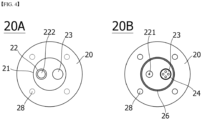
- FIG. 4 is a schematic view showing the upper jig 20 of a jig for measuring internal pressure, in which 20A is a plan view of the upper jig 20 facing the lower jig 10, and 20B is a plan view of the upper jig 10 exposed in the outer direction.
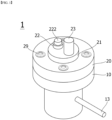
- FIG. 5 is a three-dimensional view showing one surface of the upper jig 20.
- the upper jig 20 is provided with a pressure measuring unit 21, and the pressure measuring unit 21 includes a gas discharge induction unit 22 for forming a hole in the cylindrical battery cell, and a pressure sensor 23 for measuring the pressure of the gas discharged by the operation of the gas discharge induction unit 22 so that the gas inside the cylindrical battery cell can be discharged.
- the pressure measuring unit 21 includes a gas discharge induction unit 22 for forming a hole in the cylindrical battery cell, and a pressure sensor 23 for measuring the pressure of the gas discharged by the operation of the gas discharge induction unit 22 so that the gas inside the cylindrical battery cell can be discharged.
- the gas discharge induction unit 22 has a structure penetrating the upper jig 20. Specifically, the gas discharge induction unit 22 includes a gas discharge operation switch 222 exposed toward the outside direction, has one side of a sharp shape, and includes a support unit 223 which forms a hole in the loaded cylindrical battery cell.
- the gas discharge operation switch 222 is exposed to the outside of the jig and is a physical switch for forming a hole on one surface of the loaded cylindrical battery cell when the user measures the internal pressure. That is, when the user pushes the gas discharge operation switch 222, the support unit 223 positioned toward the inside of the jig moves in the loaded cylindrical battery cell direction. As such, the support unit 223 allows gas to penetrate the lower surface of the battery cell to thereby be discharged from the inside of the battery cell into the jig. Conversely, when the gas discharge operation switch 222 is pulled, the internal support unit 223 returns to its original position.
- the gas discharge operation switch 222 is characterized in that it includes a spring 223 therein for the push/pull operation.
- the spring 223 By including the spring 223 therein, when the user pushes the gas discharge operation switch 222 once, a hole is formed in the battery cell through the internal support unit 223, and then when pushed once again, the support unit 223 is returned to the original position by the spring 223.
- the support unit 223 is for forming a hole in a cylindrical battery cell, but is preferably in the shape of a needle or cone, but is not limited thereto.
- An object having a sharp shape for forming a hole on one surface of the cylindrical battery cell can be used as the support unit 223 of the present invention.
- the pressure measuring unit 21 of the present invention includes a pressure sensor 23 for measuring the pressure of the gas discharged by the operation of the gas discharge induction unit 22.
- the pressure sensor 23 has a structure penetrating the upper jig 20. To this end, referring to FIG. 4 , a pressure sensor hole 24 is formed.
- the pressure sensor hole 24 provides an installation space of the pressure sensor 23.
- the pressure sensor hole 24 is formed along the periphery of the pressure sensor 23 on one surface of the upper jig 20 when the pressure sensor 23 is combined with the upper jig 20, as shown in FIGS. 4 and 5 .
- a sealing material is applied and sealed along the outer circumference of the pressure sensor hole 24. That is, the pressure sensor hole 24 is sealed through the sealing material in a state that the pressure sensor 23 penetrates the upper jig 20. This is to completely seal a space between the pressure sensor 23 and the pressure sensor hole 24.
- the material of the sealing material is not particularly limited, and may be, for example, silicone rubber.
- the upper jig 20 of the present invention may further include a sealing member 26 corresponding to the circumference of the receiving groove 11 of the lower jig 10 when engaged with the lower jig 10.
- the sealing member 26 is formed on one surface of the upper jig 20 facing the lower jig 10.
- the sealing member 26 is a member for sealing a space between the receiving groove 11 and the upper jig 20. As shown in FIG. 4 , the sealing member 26 is formed on one surface of the upper jig 20 and is formed to correspond to the receiving groove 11 of the lower jig 10.
- the installation method of a sealing member 26 is not specifically limited. In the present invention, preferably, a sealing groove (not shown) formed along the circumference of the receiving groove 11 may be further provided to install the sealing member 26.
- the sealing member 26 may be formed by applying a sealing material to the sealing groove so that the upper jig 20 is in contact with the lower jig 10 by pressure when the opening of the receiving groove 11 is closed. That is, it is to completely seal a space between the receiving groove 11 and the upper jig 20.
- the material of the sealing material is not particularly limited, and may be, for example, silicone rubber.
- the jig for measuring internal pressure 1 further includes a temperature measuring unit 12 and a display unit 30 for displaying the temperature and pressure measured by the pressure measuring unit 21, respectively.
- the temperature measuring unit 12 and the pressure measuring unit 21 are connected to the display unit 30.
- the display unit 30 may synthesize the temperature data and pressure data received from the temperature measuring unit 12 and the pressure measuring unit 21 to thereby generate data of temperature and pressure in which the internal gas is generated, and output the collected data as images.
- the display unit 30 can also display the quantitative and qualitative analysis data of the internal gas and the corrected data of the pressure value according to the temperature value.
- the display unit 30 may further include a control unit and a display.
- a jelly-roll type (wound) electrode assembly 710 is accommodated in a receiving portion of the cylindrical can 720, the electrolyte is injected into the receiving portion so that the electrode assembly 710 is completely immersed in the cylindrical can 720, and a cap assembly 732 is mounted and coupled to an open top end of the cylindrical can 720.
- the electrode assembly 710 has a structure in which a positive electrode 713, a separator 712, and a negative electrode 711 are sequentially stacked and wound in a round shape, and a cylindrical center pin (not shown) may be inserted into the center of the electrode assembly 710.
- the center pin is generally made of a metal material to impart a predetermined strength, and has a hollow cylindrical structure in which a plate is rounded. In some cases, the center pin may be removed after welding the electrode of the electrode assembly 710 to the cylindrical can 720 or the cap assembly 732.
- the cap assembly 732 has a structure in which the upper cap 731 and the internal pressure drop safety vent are in close contact with each other at the inside of the airtight gasket mounted on the upper inner surface of the crimping part and the beading part 740 of the cylindrical can 720, the upper cap 731 protrudes upward and serves as a positive electrode, and a plurality of through-holes through which the gas inside the can may be discharged may be formed along the periphery of the protrusion.
- a positive electrode tab protrudes from the insulating plate in the upper axial direction at the center of the electrode assembly 710 to be electrically connected to the upper cap 731 of the cap assembly 732 to apply an electric current.
- a safety vent 734 is a thin film structure through which a current flows, and a central portion thereof is recessed to form an indented central portion, and two notches reaching depths are formed at the upper and lower bending portions of the central portion.
- An insulating plate 733 is mounted on the upper surface of the electrode assembly 710 to prevent contact with the electrode lead, thereby preventing a short circuit due to contact between the electrode assembly 710 and the electrode lead.
- the cylindrical can 720 may be made of metal, preferably made of stainless steel.
- the cylindrical can 720 may include a receiving unit in which the electrode assembly 710 may be accommodated, and the upper end part may be open.
- the positive electrode tab of the electrode assembly 710 is protruded in the upper axial direction from the insulating plate 733 to be coupled to the upper cap of the cap assembly by spot welding and may be electrically connected to make the electricity.
- the negative electrode tab of the electrode assembly may be spot welded to the lower inner surface of the cylindrical can and electrically connected to apply electric current.
- the cylindrical battery cell used in the present invention includes two or more unit electrodes including a positive electrode or a negative electrode, and an electrode assembly, which is wound in a state where a separator is interposed between the unit electrodes, is embedded in the battery case.
- the unit electrode may be manufactured by applying an electrode mixture containing an electrode active material on a current collector and then drying the electrode mixture.
- the electrode mixture may further include a binder, a conductive material, a filler, and the like, as necessary.
- Both weak magnetic and nonmagnetic metal ultrathins may be used as the current collector.
- the positive electrode collector generally has a thickness of 3 to 500 micrometers.
- the positive electrode current collector is not particularly limited as long as it has high conductivity without causing a chemical change in the battery.
- Examples of the positive electrode current collector include stainless steel, aluminum, nickel, titanium, or aluminum or stainless steel of which the surface has been treated with carbon, nickel, titanium, silver, or the like.
- the current collector may have fine irregularities on the surface thereof to increase the adhesion of the positive electrode active material, and various forms such as a sheet, a foil, and a net are possible.
- the negative electrode collector generally has a thickness of 3 to 500 micrometers.
- the negative electrode current collector is not particularly limited as long as it has electrical conductivity without causing chemical changes in the battery, and examples thereof include copper, stainless steel, aluminum, nickel, titanium, sintered carbon, copper or stainless steel of which the surface has been treated with carbon, nickel, titanium, silver or the like, aluminum-cadmium alloy, or the like.
- fine unevenness can be formed on the surface to enhance the bonding force of the negative electrode active material, and it can be used in various forms such as a sheet, a foil, and a net.
- the positive electrode active material is a material capable of causing an electrochemical reaction and a lithium transition metal oxide, and contains two or more transition metals.
- the negative electrode active material examples include carbon such as non-graphitized carbon and graphite carbon; metal complex oxide such as Li x Fe 2 O 3 (0 ⁇ x ⁇ 1), Li x WO 2 (0 ⁇ x ⁇ 1), Sn x Me 1-x Me' y O z (Me: Mn, Fe, Pb, Ge; Me': Al, B, P, Si, groups 1, 2, and 3 of the periodic table, halogen; 0 ⁇ x ⁇ 1; 1 ⁇ y ⁇ 3; 1 ⁇ z ⁇ 8); lithium alloy; silicon alloy; tin alloy; metal oxides such as SnO, SnO 2 , PbO, PbO 2 , Pb 2 O 3 , Pb 3 O 4 , Sb 2 O 3 , Sb 2 O 4 , Sb 2 O 5 , GeO, GeO 2 , Bi 2 O 3 , Bi 2 O 4 , and Bi 2 O 5 ; conductive polymers such as polyacetylene; and Li-Co-Ni-based materials.
- metal complex oxide such as Li
- the conductive material is usually added in an amount of 1 to 30% by weight based on the total weight of the mixture including the positive electrode active material.
- a conductive material is not particularly limited as long as it has electrical conductivity without causing a chemical change in the battery, and examples thereof include graphite such as natural graphite and artificial graphite; carbon black such as carbon black, acetylene black, Ketjen black, channel black, furnace black, lamp black, and thermal black; conductive fibers such as carbon fiber and metal fiber; metal powders such as carbon fluoride, aluminum and nickel powder; conductive whiskey such as zinc oxide and potassium titanate; conductive metal oxides such as titanium oxide; and conductive materials such as polyphenylene derivatives and the like.
- the binder is added in an amount of 1 to 30% by weight, on the basis of the total weight of the mixture containing the positive electrode active material, as a component that assists in bonding between the active material and the conductive material and bonding to the current collector.
- binders include polyvinylidene fluoride, polyvinyl alcohol, carboxymethylcellulose (CMC), starch, hydroxypropylcellulose, regenerated cellulose, polyvinylpyrrolidone, tetrafluoroethylene, polyethylene, polypropylene, ethylene-propylene-diene terpolymer (EPDM), sulfonated EPDM, styrene butylene rubber, fluorine rubber, various copolymers and the like.
- the filler is optionally used as a component for inhibiting expansion of an electrode, and is not particularly limited as long as it is a fibrous material without causing a chemical change in the battery.
- the filler include olefin polymers such as polyethylene and polypropylene; fibrous materials such as glass fibers and carbon fibers.
- the viscosity modifier is a component that adjusts the viscosity of the electrode mixture so that the mixing process of the electrode mixture and the coating process on the current collector thereof may be easy, and may be added up to 30% by weight based on the total weight of the negative electrode mixture.
- examples of such a viscosity modifier include carboxy methyl cellulose, polyvinylidene fluoride, and the like, but are not limited thereto.
- the solvent described above may serve as a viscosity modifier.
- the adhesion promoter is an auxiliary component added to improve the adhesion of the active material to the current collector and may be added in less than 10% by weight compared to the binder, and some examples thereof include oxalic acid, adipic acid, formic acid, acrylic acid derivatives, itaconic acid derivatives, and the like.
- the separator is interposed between the positive electrode and the negative electrode, and an insulating thin film having high ion permeability and mechanical strength is used.
- the pore diameter of the separator is generally 0.01 to 10 micrometers, and the thickness is generally 5 to 300 micrometers.
- Examples of such a separator include olefin-based polymers such as polypropylene which is chemically resistant and hydrophobic; a sheet or a nonwoven fabric made of glass fiber, polyethylene or the like.
- the solid electrolyte such as a polymer
- the solid electrolyte may also serve as a separator.
- the lithium salt-containing non-aqueous electrolyte solution consists of an electrolyte and a lithium salt. And a non-aqueous organic solvent, an organic solid electrolyte, an inorganic solid electrolyte, and the like are used as the electrolyte solution.
- non-aqueous organic solvent examples include N-methyl-2-pyrrolidinone, propylene carbonate, ethylene carbonate, butylenecarbonate, dimethyl carbonate, diethyl carbonate, gamma-Butyrolactone, 1,2-dimethoxyethane, tetrahydroxyfuran, 2-methyltetrahydrofuran, dimethylsulfoxide, 1,3-dioxolane, formamide, dimethylformamide, dioxolane, acetonitrile, nitromethane, methyl formate, methyl acetate, phosphoric acid triester, trimethoxymethane, dioxolane derivatives, sulfolane, methyl sulfolane, 1,3-dimethyl-2-imidazolidinone, propylene carbonate derivatives, tetrahydrofuran derivatives, ethers, methyl pyrophosphate, ethyl propionate, etc.
- organic solid electrolyte examples include a polymer electrolyte such as a polyethylene derivative, a polyethylene oxide derivative, a polypropylene oxide derivative, a phosphate ester polymer, an agitation lysine, a polyester sulfide, a polyvinyl alcohol, a polyvinylidene fluoride, a polymerizer including an ionic dissociation group, and the like.
- a polymer electrolyte such as a polyethylene derivative, a polyethylene oxide derivative, a polypropylene oxide derivative, a phosphate ester polymer, an agitation lysine, a polyester sulfide, a polyvinyl alcohol, a polyvinylidene fluoride, a polymerizer including an ionic dissociation group, and the like.
- Examples of the inorganic solid electrolyte include nitrides, halides, and sulfates of Li such as Li 3 N, LiI, Li 5 NI 2 , Li 3 N-LiI-LiOH, LiSiO 4 , LiSiO 4 -LiI-LiOH, Li 2 SiS 3 , Li 4 SiO 4 , Li 4 SiO 4 -LiI-LiOH, and Li 3 PO 4 -Li 2 S-SiS 2 .
- Li 3 N, LiI, Li 5 NI 2 Li 3 N-LiI-LiOH, LiSiO 4 , LiSiO 4 -LiI-LiOH, Li 2 SiS 3 , Li 4 SiO 4 , Li 4 SiO 4 -LiI-LiOH, and Li 3 PO 4 -Li 2 S-SiS 2 .
- the lithium salt is a substance that is soluble in the non-aqueous electrolyte.
- the examples of the lithium salt include LiCl, LiBr, LiI, LiClO 4 , LiBF 4 , LiB 10 Cl 10 , LiPF 6 , LiCF 3 SO 3 , LiCF 3 CO 2 , LiAsF 6 , LiSbF 6 , LiAlCl 4 , CH 3 SO 3 Li, (CF 3 SO 2 ) 2 NLi, chloroborane lithium, lower aliphatic carboxylic acid lithium, lithium 4-phenylborate, imide and the like.
- pyridine triethylphosphite, triethanolamine, cyclic ether, ethylenediamine, n-glyme, hexaphosphoric triamide, nitrobenzene derivative, sulfur, quinone imine dye, N-substituted oxazolidinone, N-substituted imidazolidine, ethylene glycol dialkyl ether, ammonium salt, pyrrole, 2-methoxyethanol, aluminum trichloride, etc. may be added to the electrolyte.
- a halogen-containing solvent such as carbon tetrachloride or ethylene trifluoride may be further added to impart nonflammability, or a carbon dioxide gas may be further added to improve the high-temperature storage characteristics, and FEC (Fluoro-EthyleneCarbonate), PRS (Propene sultone), and the like may be further added.
- a lithium salt such as LiPF 6 , LiClO 4 , LiBF 4 , and LiN(SO 2 CF 3 ) 2 may be added to a mixed solvent of a cyclic carbonate of EC or PC which is a high-dielectric solvent and a linear carbonate of DEC, DMC or EMC which is low viscosity solvent to thereby prepare a non-aqueous electrolyte containing a lithium salt.
- the above-described jig for measuring internal pressure exhibits effects capable of accurately measuring the internal pressure of the cylindrical battery cell of the secondary battery.
- the jig for measuring internal pressure of the present invention when a cylindrical battery cell is loaded and gas is ejected from the battery cell after the upper and lower jigs are fastened, it is possible to minimize the accommodation space, thereby exhibiting the effect of more accurately performing internal pressure measurement.
- the cell gas generating unit and the cell internal pressure measuring unit are placed in the same space, thereby exhibiting the effect of reducing the errors of internal pressure measurement.
- the jig for measuring internal pressure of the present invention includes a temperature measuring unit capable of measuring and monitoring from the outside of the jig, so it is possible to detect and check the temperature change in real-time when measuring the inner pressure, thereby minimizing the occurrence of errors during pressure correction.
Landscapes
- Engineering & Computer Science (AREA)
- Manufacturing & Machinery (AREA)
- Chemical & Material Sciences (AREA)
- Chemical Kinetics & Catalysis (AREA)
- Electrochemistry (AREA)
- General Chemical & Material Sciences (AREA)
- Physics & Mathematics (AREA)
- General Physics & Mathematics (AREA)
- Secondary Cells (AREA)
Description
- This application claims the benefit of priority based on
Korean Patent Application No. 10-2018-0153835, filed on December 3, 2018 - The present invention relates to a jig for measuring internal pressure of a cylindrical battery cell, and more particularly, to a jig for measuring internal pressure of a cylindrical battery cell capable of correcting the result of the internal pressure measurement according to temperature, in which a pressure sensor and a gas discharge induction unit are located in the same space.
- As the price of energy sources increases due to depletion of fossil fuels and the interest in environmental pollution increases, the demand for environmentally friendly alternative energy sources becomes an indispensable factor for future life. Especially, as technology development and demand for mobile devices are increasing, demand for secondary batteries as energy sources is rapidly increasing.
- Typically, in terms of the shape of the battery, there is a high demand for a prismatic secondary battery and a pouch-type secondary battery that can be applied to products such as mobile phones with a small thickness. In terms of materials, there is a high demand for lithium secondary batteries such as lithium ion batteries and lithium ion polymer batteries having high energy density, discharge voltage, and output stability.
- Generally, in order to prepare a secondary battery, first, a positive electrode and a negative electrode are formed by applying an electrode mixture containing an electrode active material to a surface of a current collector, then a separate is interposed therebetween to thereby make an electrode assembly, which is then mounted in a cylindrical or rectangular metal can or inside a pouch-type case of an aluminum laminate sheet, and a liquid electrolyte is injected or impregnated into the electrode assembly or a solid electrolyte to prepare a secondary battery.
- One of the main research tasks of the secondary battery as described above is to improve the safety of the secondary battery. The secondary battery has a number of problems that threaten the safety of the secondary battery, such as internal short circuit due to external shock, overcharge, heat generation by over-discharge, etc., and decomposition of electrolytes due thereto, thermal runaway, etc.
- In particular, the explosion of the secondary battery originates from various causes, but an increase in gas pressure inside the secondary battery also becomes a cause according to the decomposition of the electrolyte. Specifically, when the secondary battery is repeatedly charged and discharged, gas is generated through an electrochemical reaction by the electrolyte and the electrode active material. At this time, the generated gas increases the internal pressure of the secondary battery, causing weakening of fastening between parts, damage to the external battery case of the secondary battery, premature operation of the protection circuit, deformation of the electrode, internal short circuit, and explosion, etc.
- In order to solve the safety problem of the secondary battery as described above, it was necessary to check the occurrence of a problem through a device for measuring the internal pressure during charging and discharging of the secondary battery. Examples of apparatus for measuring the internal pressure of a battery cell are disclosed
JP 2001 332312 CN 101 281 984 , andCN 102 868 003 . - The conventional pressure measuring device of a battery cell has used a method in which a cell is drilled in a battery cell and a gas is diffused into a space inside the device to perform measurement. In this regard,
Korean Patent Publication No. 10-2010-0088927 - In addition, since the space inside the conventional pressure-resistant measuring device is wider than the space inside the cell to be mounted, there is a problem in that gas discharged from the battery cell is located in an unnecessarily wide space. For this reason, it was necessary to minimize the gas flow space in the device when gas is discharged from the battery cell.
- In addition, since the pressure measuring unit and the gas discharge unit are conventionally separated, not only the error value is large, but also the measured pressure value has an error due to the temperature change. As such, in the process of correcting the pressure result value according to the temperature, it was difficult to perform precise internal pressure measurement as the error increased.
- The present invention was designed to solve the above problems, and an object of the present invention is to provide a jig for measuring internal pressure capable of accurately checking the internal pressure result of a cylindrical battery cell by allowing correction of internal pressure according to temperature change by locating the gas discharge unit and the pressure measuring unit in the same space for measurement of internal pressure of the cylindrical battery cell, and installing the temperature sensor in contact with the loaded cylindrical battery cell.
- In addition, an object of the present invention is to provide an internal pressure measuring jig that enables precise internal pressure measurement by minimizing a gas discharge space by fastening an upper jig and a lower jig.
- According to the present invention, there is provided A jig for measuring internal pressure of a cylindrical battery cell, including: a lower jig configured to have a shape corresponding to that of the cylindrical battery cell, and include a receiving groove, into which the cylindrical battery cell is detachably fitted, and a temperature measuring unit; and an upper jig including a pressure measuring unit and being detachably coupled with the lower jig to close an opening of the receiving groove.
- The temperature measuring unit may include a temperature sensor extending into the receiving groove to measure the temperature of the cylindrical battery cell, and the lower jig may further include a temperature sensor hole through which the temperature sensor passes. In this case, the temperature sensor hole may be sealed by applying a sealing material in a state that the temperature sensor is penetrated, and the temperature sensor may be a thermocouple in which stainless (SUS) wire is covered by an insulating member.
- The pressure measuring unit includes: a gas discharge induction unit for forming a hole in the cylindrical battery cell to discharge gas from inside the cylindrical battery cell; and a pressure sensor for measuring a pressure of the gas discharged by operation of the gas discharge induction unit. Herein, the upper jig further includes a pressure sensor hole through which the pressure sensor passes. The pressure sensor hole may be sealed by applying a sealing material in a state that the pressure sensor is penetrated.
- Herein, the gas discharge induction unit may include a support unit having a sharp shape on one surface and forming a hole in the cylindrical battery cell, and a gas discharge operation switch connected to the support unit and moving the support unit in a direction of the cylindrical battery cell, and the support unit may have a needle or cone shape. Further, the gas discharge operation switch may include a spring therein for a push/pull scheme.
- According to an embodiment of the present invention, the upper jig may be provided with a sealing member for sealing a space between the receiving groove and the upper jig. Specifically, the upper jig may further include a sealing groove formed along a circumference of the receiving groove, and the sealing member may be formed by applying a sealing material on the sealing groove to be in pressure contact with the lower jig when the upper jig closes an opening of the receiving groove.
- According to another embodiment of the present invention, the jig may further include a coupling member configured to closely couple the upper jig to the lower jig. Specifically, the lower jig may further include at least one lower coupling hole, the upper jig may further include at least one upper coupling hole corresponding to the lower coupling hole, and the coupling member may be provided with a coupling bolt screwed to the lower coupling hole and the upper coupling hole.
- According to another embodiment of the present invention, the jig for measuring internal pressure of the cylindrical battery cell of the present invention may further include a display unit for displaying a temperature and a pressure measured by the temperature measuring unit and the pressure measuring unit.
- According to the present invention, when measuring the internal pressure for setting the open pressure of a current interruptive device (CID) at the time of designing a cylindrical battery cell, by positioning the gas discharge unit and the pressure measuring unit inside the jig for measuring the internal pressure in the same space, the discharged gas is discharged to the pressure measuring unit and the gas flow space is minimized, thereby reducing the error in pressure measurement, thereby enabling precise measurement.
- In addition, in order to correct the pressure according to the temperature change due to gas discharge, the temperature measuring unit was designed to penetrate the lower jig in the present invention. As such, as one side of the temperature measuring unit comes into contact with the cylindrical battery cell to be mounted and the other side is exposed outside the jig, it is possible to measure and monitor the temperature of the cylindrical battery cell from the outside, and to minimize the occurrence of errors during pressure correction according to real-time monitoring.
-
-
FIG. 1 is a combined schematic view showing a jig for measuring internal pressure of a cylindrical battery cell of the present invention. -
FIG. 2 is a separated schematic view showing a jig for measuring internal pressure of a cylindrical battery cell of the present invention. -
FIG. 3 is a top/bottom/side sectional view of a lower jig of the present invention. -
FIG. 4 is a top/bottom sectional view of an upper jig of the present invention. -
FIG. 5 is a three-dimensional view showing one surface of the upper jig of the present invention. -
FIG. 6 is a schematic diagram showing connection between a jig for measuring internal pressure and a display unit of the present invention. -
FIG. 7 is a cross-sectional view showing a cylindrical battery cell loaded in a jig for measuring internal pressure of the present invention. - Hereinafter, preferred embodiments of the present invention will be described in detail with reference to the accompanying drawings. The terms and words used in the present specification and claims should not be construed as limited to ordinary or dictionary terms and the inventor may properly define the concept of the terms in order to best describe its invention. The terms and words should be construed as meaning and concept consistent with the technical idea of the present invention. Accordingly, the embodiments described in the specification and the configurations described in the drawings are only the most preferred embodiments of the present invention, and do not represent all of the technical ideas of the present invention. It is to be understood that there may be various equivalents and variations in place of them at the time of filing the present application.
- In general, in secondary batteries, swelling occurs under abnormal conditions such as overcharge, overdischarge, short circuit, and overcurrent. In this case, the degree of swelling cannot be accurately detected in real time. The swelling phenomenon of the secondary battery refers to a phenomenon in which the internal pressure of the battery cell increases rapidly and the external side, case, etc. of the battery swell. This swelling phenomenon is due to a phenomenon in which gas is generated by heat generation or ignition of the electrode of the secondary battery, or gas is generated by decomposition of the electrolyte by overvoltage.
- When gas is generated in the battery as described above, an explosion of the secondary battery may be caused, and such an explosion may not only destroy the pack of the secondary battery or devices including the same, but also injure the user.
- In addition, damage to the battery case due to explosion of the secondary battery may cause leakage of the electrolyte provided in the secondary battery, and may cause damage such as short circuit, electric shock, or fire.
- Accordingly, an object of the present invention is to provide a precise jig for measuring the internal pressure when designing a cylindrical battery cell to prevent such problems. In the jig for measuring internal pressure according to the present invention, the pressure sensor and the gas discharge induction unit are placed in the same space, it is possible to minimize the gas flow space compared to the conventional one as being equipped with the temperature measuring unit, and it is possible to correct the pressure measurement value according to real-time temperature monitoring, thereby exhibiting the effects of allowing precise internal pressure measurement.
- Hereinafter, a jig for measuring internal pressure of the present invention will be described.
-
FIG. 1 is a schematic diagram showing a combined state of a jig for measuring internal pressure of a battery cell according to an embodiment of the present invention, andFIG. 2 is a schematic diagram showing a separated state of a jig for measuring internal pressure of the present invention. - Referring to
FIGS. 1 and2 , ajig 1 for measuring internal pressure of a cylindrical battery cell according to an aspect of the present invention includes: alower jig 10 configured to have a shape corresponding to that of the cylindrical battery cell, and include a receivinggroove 11, into which the cylindrical battery cell is detachably fitted, and atemperature measuring unit 12; and anupper jig 20 configured to include apressure measuring unit 21 that discharges gas inside the cylindrical battery cell and measures a pressure of the discharged gas, and be detachably coupled with thelower jig 10 to close an opening of the receivinggroove 11. - The
pressure measuring unit 21 of theupper jig 20 includes a gasdischarge induction unit 22 and apressure sensor 23 including a gasdischarge operation switch 222. In addition, as shown inFIG. 1 , thelower jig 10 and theupper jig 20 are sealed and fastened to each other. - The above sealing fastening structure of the
lower jig 10 and theupper jig 20 is used not to deviate from the originally loaded position or state or to deviate significantly in order to accurately measure the internal pressure of the cylindrical battery cell. - In the present invention, the cylindrical battery cell whose internal pressure is measured is loaded into the receiving
groove 11 of thelower jig 10. At this time, the loading direction of the cylindrical battery cell loads the battery cell such that the bottom surface of the battery cell faces upward. This is because the thickness of the cylindrical battery cell is too thick to penetrate the upper cap. That is, by loading such that the bottom of the battery cell becomes the upper part, a hole is well formed in the bottom of the battery cell through the pressure measuring unit of the jig of the present invention described later, so that the gas inside the battery cell can be easily discharged. -
FIG. 2 is a separated schematic view showing a jig for measuring internal pressure of the present invention. Thelower coupling hole 18 formed at the edge of thelower jig 10 and theupper coupling hole 28 formed at the edge of theupper jig 20 are formed at positions corresponding to each other. Thelower coupling hole 18 and theupper coupling hole 28 provide an installation space of the coupling bolt of thecoupling member 29 to be described later. A plurality of upper coupling holes 28 are formed at predetermined intervals along the edge of theupper jig 20 so as to correspond to the lower coupling holes 18, respectively. At the same time, a plurality of lower coupling holes 18 are also formed at predetermined intervals along the edge of thelower jig 10 so as to correspond to the upper coupling holes 28, respectively. - The
coupling member 29 is a member for closely coupling thelower jig 10 and theupper jig 20 so that the receivinggroove 11 is closed. As shown inFIG. 2 , thecoupling member 29 includes a plurality of coupling bolts screwed with thelower coupling hole 18 and theupper coupling hole 28, and a nut which is screwed with the coupling bolt to allow thelower jig 10 to be in close contact with theupper jig 20. - The head of the coupling bolt is supported on the upper surface of the
upper jig 20, and the end portion of the coupling bolt is screwed to theupper coupling hole 28 and thelower coupling hole 18 to penetrate thelower jig 10. Correspondingly, the nut is screwed into the end portion of the coupling bolt passing through thelower coupling hole 18. Then, thelower jig 10 and theupper jig 20 are tightened by the bolt head and the nut to be tightly coupled. -
FIG. 3 is a schematic view showing thelower jig 10 of a jig for measuring internal pressure, in which 10A is a plan view of thelower jig 10 facing theupper jig lower jig 10 exposed in the outer direction, and 10C is a side view of thelower jig 10. - First, referring to 10A, the receiving
groove 11 is a space in which a cylindrical battery cell for measuring pressure is received by discharging internal gas. The inner portion is preferably formed of a metal material, but is not limited thereto. In addition, it has a shape corresponding to the cylindrical battery cell so that the cylindrical battery cell can be fitted for separation and loading. As in the present invention, since the receivinggroove 11 has a shape corresponding to that of the cylindrical battery cell, when internal gas is generated inside the cylindrical battery cell, the internal gas is discharged into the receiving groove of the lower jig and the gas flow space can be minimized. Minimizing the flow space of the gas exerts an effect of increasing the precision of pressure measurement according to gas discharge. - In addition, the
lower jig 10 is characterized in that it has atemperature measuring unit 12 on the side. Thetemperature measuring unit 12 is provided on one side of thelower jig 10, as shown in 10A and 10B. Although onetemperature measuring unit 12 is provided in the present application, two or more may be provided for precise temperature measurement. - Specifically, the
temperature measuring unit 12 includes atemperature sensor 13 extending into the receivinggroove 11 to measure the temperature of the cylindrical cell, and atemperature sensor hole 14 through which thetemperature sensor 13 passes. - First, the
temperature sensor 13 is characterized in that a stainless (SUS) wire is a thermocouple covered with an insulating member. The temperature of the cylindrical battery cell is measured through thetemperature sensor 13, and the temperature change outside the jig can be monitored in real time. In the present invention, by using a stainless steel wire as thetemperature sensor 13, it is strong even in corrosion and high temperature, robust against external shocks and vibrations, and is rapid and precise in reaction. - In addition, the
temperature sensor 13 has a structure penetrating thelower jig 10. One side of thetemperature sensor 13 is in contact with the receivinggroove 11, and the other side is exposed to the outside of the jig. - The
temperature sensor hole 14 is a hole formed on thelower jig 10 through which thetemperature sensor 13 penetrates, as shown in 10C, and is formed to correspond to the diameter of thetemperature sensor 13. That is, it has a structure capable of measuring temperature by making contact with a cylindrical battery cell into which thetemperature sensor 13 is loaded through thetemperature sensor hole 14 generated on one side of thelower jig 10. - Here, it is characterized in that a sealing material is applied and sealed along the outer periphery of the
temperature sensor hole 14 in a state in which thetemperature sensor 13 is penetrated and coupled through thetemperature sensor hole 14. The material of the sealing material is not particularly limited. For example, the sealing material may be silicon rubber. Gas leakage to the outside is prevented through thetemperature sensor hole 14 through the application of sealing material, and by preventing the drop of the pressure due thereto, precise pressure measurement becomes possible. - In addition, according to another embodiment of the present invention, a display unit for displaying the temperature value measured from the
temperature sensor 13 may be further included. The display means for implementing such a display unit can be controlled through a control device such as a computer, and can be confirmed through a display connected thereto. That is, thetemperature sensor 13 can monitor the surface temperature of the cylindrical battery cell from the outside in real time. - In a conventional battery cell, the internal pressure measuring unit was not included, and it was common to measure only the internal pressure value according to gas ejection. Herein, since the internal pressure of a battery cell measured according to a conventional method has a large error due to a change in temperature, a work for correcting the error was required separately. However, since the
jig 1 for measuring internal pressure according to the present invention is provided with atemperature measuring unit 12, not only it is possible to perform temperature measurement and monitoring of the battery cell from the outside, but also it is possible to perform pressure correction according to accurate temperature measurement, thereby exhibiting the effect of allowing precise internal pressure measurement. -
FIG. 4 is a schematic view showing theupper jig 20 of a jig for measuring internal pressure, in which 20A is a plan view of theupper jig 20 facing thelower jig upper jig 10 exposed in the outer direction.FIG. 5 is a three-dimensional view showing one surface of theupper jig 20. - First, referring to 20A of
FIG. 4 , theupper jig 20 is provided with apressure measuring unit 21, and thepressure measuring unit 21 includes a gasdischarge induction unit 22 for forming a hole in the cylindrical battery cell, and apressure sensor 23 for measuring the pressure of the gas discharged by the operation of the gasdischarge induction unit 22 so that the gas inside the cylindrical battery cell can be discharged. - Referring to
FIG. 5 , first, the gasdischarge induction unit 22 has a structure penetrating theupper jig 20. Specifically, the gasdischarge induction unit 22 includes a gasdischarge operation switch 222 exposed toward the outside direction, has one side of a sharp shape, and includes asupport unit 223 which forms a hole in the loaded cylindrical battery cell. - First, the gas
discharge operation switch 222 is exposed to the outside of the jig and is a physical switch for forming a hole on one surface of the loaded cylindrical battery cell when the user measures the internal pressure. That is, when the user pushes the gasdischarge operation switch 222, thesupport unit 223 positioned toward the inside of the jig moves in the loaded cylindrical battery cell direction. As such, thesupport unit 223 allows gas to penetrate the lower surface of the battery cell to thereby be discharged from the inside of the battery cell into the jig. Conversely, when the gasdischarge operation switch 222 is pulled, theinternal support unit 223 returns to its original position. - In the present invention, as shown in
FIG. 5 , the gasdischarge operation switch 222 is characterized in that it includes aspring 223 therein for the push/pull operation. By including thespring 223 therein, when the user pushes the gasdischarge operation switch 222 once, a hole is formed in the battery cell through theinternal support unit 223, and then when pushed once again, thesupport unit 223 is returned to the original position by thespring 223. - The
support unit 223 is for forming a hole in a cylindrical battery cell, but is preferably in the shape of a needle or cone, but is not limited thereto. An object having a sharp shape for forming a hole on one surface of the cylindrical battery cell can be used as thesupport unit 223 of the present invention. - In addition, the
pressure measuring unit 21 of the present invention includes apressure sensor 23 for measuring the pressure of the gas discharged by the operation of the gasdischarge induction unit 22. - First, the
pressure sensor 23 has a structure penetrating theupper jig 20. To this end, referring toFIG. 4 , apressure sensor hole 24 is formed. - The
pressure sensor hole 24 provides an installation space of thepressure sensor 23. Thepressure sensor hole 24 is formed along the periphery of thepressure sensor 23 on one surface of theupper jig 20 when thepressure sensor 23 is combined with theupper jig 20, as shown inFIGS. 4 and5 . - In the present invention, a sealing material is applied and sealed along the outer circumference of the
pressure sensor hole 24. That is, thepressure sensor hole 24 is sealed through the sealing material in a state that thepressure sensor 23 penetrates theupper jig 20. This is to completely seal a space between thepressure sensor 23 and thepressure sensor hole 24. The material of the sealing material is not particularly limited, and may be, for example, silicone rubber. - Meanwhile, the
upper jig 20 of the present invention may further include a sealingmember 26 corresponding to the circumference of the receivinggroove 11 of thelower jig 10 when engaged with thelower jig 10. Specifically, referring to 20B ofFIG. 4 , it can be seen that the sealingmember 26 is formed on one surface of theupper jig 20 facing thelower jig 10. - The sealing
member 26 is a member for sealing a space between the receivinggroove 11 and theupper jig 20. As shown inFIG. 4 , the sealingmember 26 is formed on one surface of theupper jig 20 and is formed to correspond to the receivinggroove 11 of thelower jig 10. The installation method of a sealingmember 26 is not specifically limited. In the present invention, preferably, a sealing groove (not shown) formed along the circumference of the receivinggroove 11 may be further provided to install the sealingmember 26. - The sealing
member 26 may be formed by applying a sealing material to the sealing groove so that theupper jig 20 is in contact with thelower jig 10 by pressure when the opening of the receivinggroove 11 is closed. That is, it is to completely seal a space between the receivinggroove 11 and theupper jig 20. The material of the sealing material is not particularly limited, and may be, for example, silicone rubber. - According to another embodiment of the present invention, the jig for measuring
internal pressure 1 further includes atemperature measuring unit 12 and adisplay unit 30 for displaying the temperature and pressure measured by thepressure measuring unit 21, respectively. As shown inFIG. 6 , thetemperature measuring unit 12 and thepressure measuring unit 21 are connected to thedisplay unit 30. Thedisplay unit 30 may synthesize the temperature data and pressure data received from thetemperature measuring unit 12 and thepressure measuring unit 21 to thereby generate data of temperature and pressure in which the internal gas is generated, and output the collected data as images. Thedisplay unit 30 can also display the quantitative and qualitative analysis data of the internal gas and the corrected data of the pressure value according to the temperature value. To this end, thedisplay unit 30 may further include a control unit and a display. - Hereinafter, a cylindrical battery cell usable in the present invention will be described.
- Referring to
FIG. 7 , in thecylindrical battery cell 700, a jelly-roll type (wound)electrode assembly 710 is accommodated in a receiving portion of thecylindrical can 720, the electrolyte is injected into the receiving portion so that theelectrode assembly 710 is completely immersed in thecylindrical can 720, and acap assembly 732 is mounted and coupled to an open top end of thecylindrical can 720. - The
electrode assembly 710 has a structure in which apositive electrode 713, aseparator 712, and anegative electrode 711 are sequentially stacked and wound in a round shape, and a cylindrical center pin (not shown) may be inserted into the center of theelectrode assembly 710. The center pin is generally made of a metal material to impart a predetermined strength, and has a hollow cylindrical structure in which a plate is rounded. In some cases, the center pin may be removed after welding the electrode of theelectrode assembly 710 to the cylindrical can 720 or thecap assembly 732. - The
cap assembly 732 has a structure in which theupper cap 731 and the internal pressure drop safety vent are in close contact with each other at the inside of the airtight gasket mounted on the upper inner surface of the crimping part and thebeading part 740 of thecylindrical can 720, theupper cap 731 protrudes upward and serves as a positive electrode, and a plurality of through-holes through which the gas inside the can may be discharged may be formed along the periphery of the protrusion. In addition, a positive electrode tab protrudes from the insulating plate in the upper axial direction at the center of theelectrode assembly 710 to be electrically connected to theupper cap 731 of thecap assembly 732 to apply an electric current. Further, asafety vent 734 is a thin film structure through which a current flows, and a central portion thereof is recessed to form an indented central portion, and two notches reaching depths are formed at the upper and lower bending portions of the central portion. - An insulating
plate 733 is mounted on the upper surface of theelectrode assembly 710 to prevent contact with the electrode lead, thereby preventing a short circuit due to contact between theelectrode assembly 710 and the electrode lead. - The cylindrical can 720 may be made of metal, preferably made of stainless steel. In addition, the cylindrical can 720 may include a receiving unit in which the
electrode assembly 710 may be accommodated, and the upper end part may be open. - On the other hand, the positive electrode tab of the
electrode assembly 710 is protruded in the upper axial direction from the insulatingplate 733 to be coupled to the upper cap of the cap assembly by spot welding and may be electrically connected to make the electricity. In addition, the negative electrode tab of the electrode assembly may be spot welded to the lower inner surface of the cylindrical can and electrically connected to apply electric current. - Meanwhile, the cylindrical battery cell used in the present invention includes two or more unit electrodes including a positive electrode or a negative electrode, and an electrode assembly, which is wound in a state where a separator is interposed between the unit electrodes, is embedded in the battery case. In the present invention, the unit electrode may be manufactured by applying an electrode mixture containing an electrode active material on a current collector and then drying the electrode mixture. The electrode mixture may further include a binder, a conductive material, a filler, and the like, as necessary.
- Both weak magnetic and nonmagnetic metal ultrathins may be used as the current collector. The positive electrode collector generally has a thickness of 3 to 500 micrometers. The positive electrode current collector is not particularly limited as long as it has high conductivity without causing a chemical change in the battery. Examples of the positive electrode current collector include stainless steel, aluminum, nickel, titanium, or aluminum or stainless steel of which the surface has been treated with carbon, nickel, titanium, silver, or the like. The current collector may have fine irregularities on the surface thereof to increase the adhesion of the positive electrode active material, and various forms such as a sheet, a foil, and a net are possible.
- The negative electrode collector generally has a thickness of 3 to 500 micrometers. The negative electrode current collector is not particularly limited as long as it has electrical conductivity without causing chemical changes in the battery, and examples thereof include copper, stainless steel, aluminum, nickel, titanium, sintered carbon, copper or stainless steel of which the surface has been treated with carbon, nickel, titanium, silver or the like, aluminum-cadmium alloy, or the like. In addition, like the positive electrode current collector, fine unevenness can be formed on the surface to enhance the bonding force of the negative electrode active material, and it can be used in various forms such as a sheet, a foil, and a net.
- The positive electrode active material is a material capable of causing an electrochemical reaction and a lithium transition metal oxide, and contains two or more transition metals. Examples thereof include: layered compounds such as lithium cobalt oxide (LiCoO2) and lithium nickel oxide (LiNiO2) substituted with one or more transition metals; lithium manganese oxide substituted with one or more transition metals; lithium nickel oxide represented by the formula LiNi1-yMyO2 (wherein M = Co, Mn, Al, Cu, Fe, Mg, B, Cr, Zn or Ga and contains at least one of the above elements, 0.01≤y≤0.7); lithium nickel cobalt manganese composite oxide represented by the formula Li1+zNibMncCo1-(b+c+d)MdO(2-e)Ae such as Li1+zNi1/3Co1/3Mn1/3O2, Li1+zNi0.4Mn0.4Co0.2O2 etc. (wherein -0.5<z<0.5, 0.1≤b≤0.8, 0.1<c<0.8, 0≤d≤0.2, 0≤e≤0.2, b+c+d< 1, M = Al, Mg, Cr, Ti, Si or Y, and A = F, P or Cl); olivine-based lithium metal phosphate represented by the formula Li1+xM1-yM'yPO4-zXz (wherein M = transition metal, preferably Fe, Mn, Co or Ni, M'= Al, Mg or Ti, X = F, S or N, and -0.5≤x≤0.5, 0≤y≤0.5, 0≤z≤0.1).
- Examples of the negative electrode active material include carbon such as non-graphitized carbon and graphite carbon; metal complex oxide such as LixFe2O3(0≤x≤1), LixWO2(0≤x≤1), SnxMe1-xMe'yOz (Me: Mn, Fe, Pb, Ge; Me': Al, B, P, Si,
groups 1, 2, and 3 of the periodic table, halogen; 0<x≤1; 1≤y≤3; 1≤z≤8); lithium alloy; silicon alloy; tin alloy; metal oxides such as SnO, SnO2, PbO, PbO2, Pb2O3, Pb3O4, Sb2O3, Sb2O4, Sb2O5, GeO, GeO2, Bi2O3, Bi2O4, and Bi2O5; conductive polymers such as polyacetylene; and Li-Co-Ni-based materials. - The conductive material is usually added in an amount of 1 to 30% by weight based on the total weight of the mixture including the positive electrode active material. Such a conductive material is not particularly limited as long as it has electrical conductivity without causing a chemical change in the battery, and examples thereof include graphite such as natural graphite and artificial graphite; carbon black such as carbon black, acetylene black, Ketjen black, channel black, furnace black, lamp black, and thermal black; conductive fibers such as carbon fiber and metal fiber; metal powders such as carbon fluoride, aluminum and nickel powder; conductive whiskey such as zinc oxide and potassium titanate; conductive metal oxides such as titanium oxide; and conductive materials such as polyphenylene derivatives and the like.
- The binder is added in an amount of 1 to 30% by weight, on the basis of the total weight of the mixture containing the positive electrode active material, as a component that assists in bonding between the active material and the conductive material and bonding to the current collector. Examples of such binders include polyvinylidene fluoride, polyvinyl alcohol, carboxymethylcellulose (CMC), starch, hydroxypropylcellulose, regenerated cellulose, polyvinylpyrrolidone, tetrafluoroethylene, polyethylene, polypropylene, ethylene-propylene-diene terpolymer (EPDM), sulfonated EPDM, styrene butylene rubber, fluorine rubber, various copolymers and the like.
- The filler is optionally used as a component for inhibiting expansion of an electrode, and is not particularly limited as long as it is a fibrous material without causing a chemical change in the battery. Examples of the filler include olefin polymers such as polyethylene and polypropylene; fibrous materials such as glass fibers and carbon fibers.
- Other components, such as viscosity modifiers, adhesion promoters, and the like may be further included optionally or in combination of two or more. The viscosity modifier is a component that adjusts the viscosity of the electrode mixture so that the mixing process of the electrode mixture and the coating process on the current collector thereof may be easy, and may be added up to 30% by weight based on the total weight of the negative electrode mixture. Examples of such a viscosity modifier include carboxy methyl cellulose, polyvinylidene fluoride, and the like, but are not limited thereto. In some cases, the solvent described above may serve as a viscosity modifier.
- The adhesion promoter is an auxiliary component added to improve the adhesion of the active material to the current collector and may be added in less than 10% by weight compared to the binder, and some examples thereof include oxalic acid, adipic acid, formic acid, acrylic acid derivatives, itaconic acid derivatives, and the like.
- The separator is interposed between the positive electrode and the negative electrode, and an insulating thin film having high ion permeability and mechanical strength is used. The pore diameter of the separator is generally 0.01 to 10 micrometers, and the thickness is generally 5 to 300 micrometers. Examples of such a separator include olefin-based polymers such as polypropylene which is chemically resistant and hydrophobic; a sheet or a nonwoven fabric made of glass fiber, polyethylene or the like. When a solid electrolyte such as a polymer is used as the electrolyte, the solid electrolyte may also serve as a separator.
- The lithium salt-containing non-aqueous electrolyte solution consists of an electrolyte and a lithium salt. And a non-aqueous organic solvent, an organic solid electrolyte, an inorganic solid electrolyte, and the like are used as the electrolyte solution.
- Examples of the non-aqueous organic solvent include N-methyl-2-pyrrolidinone, propylene carbonate, ethylene carbonate, butylenecarbonate, dimethyl carbonate, diethyl carbonate, gamma-Butyrolactone, 1,2-dimethoxyethane, tetrahydroxyfuran, 2-methyltetrahydrofuran, dimethylsulfoxide, 1,3-dioxolane, formamide, dimethylformamide, dioxolane, acetonitrile, nitromethane, methyl formate, methyl acetate, phosphoric acid triester, trimethoxymethane, dioxolane derivatives, sulfolane, methyl sulfolane, 1,3-dimethyl-2-imidazolidinone, propylene carbonate derivatives, tetrahydrofuran derivatives, ethers, methyl pyrophosphate, ethyl propionate, etc.
- Examples of the organic solid electrolyte include a polymer electrolyte such as a polyethylene derivative, a polyethylene oxide derivative, a polypropylene oxide derivative, a phosphate ester polymer, an agitation lysine, a polyester sulfide, a polyvinyl alcohol, a polyvinylidene fluoride, a polymerizer including an ionic dissociation group, and the like.
- Examples of the inorganic solid electrolyte include nitrides, halides, and sulfates of Li such as Li3N, LiI, Li5NI2, Li3N-LiI-LiOH, LiSiO4, LiSiO4-LiI-LiOH, Li2SiS3, Li4SiO4, Li4SiO4-LiI-LiOH, and Li3PO4-Li2S-SiS2.
- The lithium salt is a substance that is soluble in the non-aqueous electrolyte. The examples of the lithium salt include LiCl, LiBr, LiI, LiClO4, LiBF4, LiB10Cl10, LiPF6, LiCF3SO3, LiCF3CO2, LiAsF6, LiSbF6, LiAlCl4, CH3SO3Li, (CF3SO2)2NLi, chloroborane lithium, lower aliphatic carboxylic acid lithium, lithium 4-phenylborate, imide and the like.
- For the purpose of improving charge/discharge characteristics, flame retardancy, etc., pyridine, triethylphosphite, triethanolamine, cyclic ether, ethylenediamine, n-glyme, hexaphosphoric triamide, nitrobenzene derivative, sulfur, quinone imine dye, N-substituted oxazolidinone, N-substituted imidazolidine, ethylene glycol dialkyl ether, ammonium salt, pyrrole, 2-methoxyethanol, aluminum trichloride, etc. may be added to the electrolyte. In some cases, a halogen-containing solvent such as carbon tetrachloride or ethylene trifluoride may be further added to impart nonflammability, or a carbon dioxide gas may be further added to improve the high-temperature storage characteristics, and FEC (Fluoro-EthyleneCarbonate), PRS (Propene sultone), and the like may be further added.
- In one preferred example, a lithium salt such as LiPF6, LiClO4, LiBF4, and LiN(SO2CF3)2 may be added to a mixed solvent of a cyclic carbonate of EC or PC which is a high-dielectric solvent and a linear carbonate of DEC, DMC or EMC which is low viscosity solvent to thereby prepare a non-aqueous electrolyte containing a lithium salt.
- The above-described jig for measuring internal pressure according to an embodiment of the present invention exhibits effects capable of accurately measuring the internal pressure of the cylindrical battery cell of the secondary battery.
- In addition, according to the jig for measuring internal pressure of the present invention, when a cylindrical battery cell is loaded and gas is ejected from the battery cell after the upper and lower jigs are fastened, it is possible to minimize the accommodation space, thereby exhibiting the effect of more accurately performing internal pressure measurement.
- In addition, according to the jig for measuring internal pressure of the present invention, when measuring the internal pressure by loading the upper jig and the lower jig, the cell gas generating unit and the cell internal pressure measuring unit are placed in the same space, thereby exhibiting the effect of reducing the errors of internal pressure measurement.
- In addition, the jig for measuring internal pressure of the present invention includes a temperature measuring unit capable of measuring and monitoring from the outside of the jig, so it is possible to detect and check the temperature change in real-time when measuring the inner pressure, thereby minimizing the occurrence of errors during pressure correction.
- While the present invention has been particularly shown and described with reference to exemplary embodiments thereof, it is to be understood that the present invention is not limited to the disclosed exemplary embodiments, and various changes and modifications may be made without departing from the technical idea of the present invention and the scope of the appended claims.
-
1: jig for measuring internal pressure 10: lower jig 11: receiving groove 12: temperature measuring unit 13: temperature sensor 14: temperature sensor hole 18: lower coupling hole 20: upper jig 21: pressure measuring unit 22: gas discharge induction unit 23: pressure sensor 24: pressure sensor hole 26: sealing member 28: upper coupling hole 29: coupling member 30: display unit 221: support unit 222: gas discharge operation switch 223: spring 700: battery cell 710: electrode assembly 711: negative electrode 712: separator 713: positive electrode 720: cylindrical can 731: upper cap 732: cap assembly 733: insulating plate 734: safety vent 735: cylindrical battery cell floor 740: crimping part and beading part
Claims (13)
- A jig for measuring internal pressure (1) of a cylindrical battery cell (700), the jig comprising:a lower jig (10) configured to have a shape corresponding to that of the cylindrical battery cell (700), and include a receiving groove (11), into which the cylindrical battery cell (700) is detachably fitted, and a temperature measuring unit (12); andan upper jig (20) including a pressure measuring unit (21) comprising:a gas discharge induction unit (22) for forming a hole in the cylindrical battery cell (700) to discharge gas from inside the cylindrical battery cell (700); anda pressure sensor (23) for measuring a pressure of the gas discharged by operation of the gas discharge induction unit (22),wherein the upper jig (20) further includes a pressure sensor hole (24) through which the pressure sensor (23) passes, andwherein the upper jig (20) is detachably coupled with the lower jig (10) to close an opening of the receiving groove (11).
- The jig (1) of claim 1, wherein the temperature measuring unit (12) includes a temperature sensor (13) extending into the receiving groove (11) to measure the temperature of the cylindrical battery cell (700),
wherein the lower jig (10) further includes a temperature sensor hole (14) through which the temperature sensor passes (13). - The jig (1) of claim 2, wherein the temperature sensor hole (14) is sealed by applying a sealing material in a state that the temperature sensor (13) is penetrated.
- The jig (1) of claim 2, wherein the temperature sensor (13) is a thermocouple in which stainless (SUS) wire is covered with an insulating member.
- The jig (1) of claim 1, wherein the pressure sensor hole (24) is sealed by applying a sealing material in a state that the pressure sensor (23) is penetrated.
- The jig (1) of claim 1, wherein the gas discharge induction unit (22) includes a support unit (221) having a sharp shape on one surface and forming a hole in the cylindrical battery cell (700), and a gas discharge operation switch (222) connected to the support unit (221) and moving the support unit (221) in a direction of the cylindrical battery cell (700).
- The jig (1) of claim 6, wherein the support unit (221) has a needle or cone shape.
- The jig (1) of claim 6, wherein the gas discharge operation switch (222) includes a spring (223) therein for a push/pull scheme.
- The jig (1) of claim 1, wherein the upper jig (20) is provided with a sealing member (26) for sealing a space between the receiving groove (11) and the upper jig (20).
- The jig (1) of claim 9, wherein the upper jig (20) further includes a sealing groove formed along a circumference of the receiving groove (11), and
wherein the sealing member (26) is formed by applying a sealing material on the sealing groove to be in pressure contact with the lower jig (10) when the upper jig (20) closes an opening of the receiving groove (11). - The jig (1) of claim 1, further comprising a coupling member (29) configured to closely couple the upper jig (20) to the lower jig (10).
- The jig (1) of claim 11, wherein the lower jig (10) further includes at least one lower coupling hole (18),wherein the upper jig (20) further includes at least one upper coupling hole (28) corresponding to the lower coupling hole (18), andwherein the coupling member (29) is provided with a coupling bolt screwed to the lower coupling hole (18) and the upper coupling hole (28).
- The jig (1) of claim 1, further comprising a display unit (30) for displaying a temperature and a pressure measured by the temperature measuring unit (12) and the pressure measuring unit (21).
Applications Claiming Priority (2)
| Application Number | Priority Date | Filing Date | Title |
|---|---|---|---|
| KR1020180153835A KR102455848B1 (en) | 2018-12-03 | 2018-12-03 | Jig for measuring internal pressure of cylindrical battery cell |
| PCT/KR2019/016462 WO2020116851A1 (en) | 2018-12-03 | 2019-11-27 | Internal pressure measuring jig for cylindrical battery cell |
Publications (3)
| Publication Number | Publication Date |
|---|---|
| EP3780247A1 EP3780247A1 (en) | 2021-02-17 |
| EP3780247A4 EP3780247A4 (en) | 2021-06-23 |
| EP3780247B1 true EP3780247B1 (en) | 2023-07-19 |
Family
ID=70975359
Family Applications (1)
| Application Number | Title | Priority Date | Filing Date |
|---|---|---|---|
| EP19893591.8A Active EP3780247B1 (en) | 2018-12-03 | 2019-11-27 | Internal pressure measuring jig for cylindrical battery cell |
Country Status (5)
| Country | Link |
|---|---|
| US (1) | US11824171B2 (en) |
| EP (1) | EP3780247B1 (en) |
| KR (1) | KR102455848B1 (en) |
| CN (1) | CN112106247A (en) |
| WO (1) | WO2020116851A1 (en) |
Families Citing this family (11)
| Publication number | Priority date | Publication date | Assignee | Title |
|---|---|---|---|---|
| CN112924865B (en) * | 2021-01-28 | 2022-11-25 | 上海化工研究院有限公司 | Rapid detection device and detection method for reliability of lithium battery current cut-off device |
| DE102021115451A1 (en) * | 2021-06-15 | 2022-12-15 | Bayerische Motoren Werke Aktiengesellschaft | Apparatus for compressing at least a portion of an energy storage cell, and system and method for electrical safety testing |
| KR102952237B1 (en) * | 2021-11-12 | 2026-04-13 | 주식회사 엘지에너지솔루션 | Battery cell internal pressure measuring apparatus |
| CN114440974B (en) * | 2022-01-18 | 2024-01-19 | 上海工程技术大学 | Battery expansion displacement and temperature in-situ measurement device |
| CN114813886B (en) * | 2022-04-24 | 2026-04-14 | 开封时代新能源科技有限公司 | Fixing clamp for electrochemical test working electrode |
| KR20230159102A (en) | 2022-05-13 | 2023-11-21 | 에스케이온 주식회사 | Secondary battery temperature measuring device |
| KR20240013382A (en) * | 2022-07-22 | 2024-01-30 | 주식회사 엘지에너지솔루션 | Apparatus for collecting gas |
| CN115479717B (en) * | 2022-08-26 | 2025-09-23 | 清华大学 | Battery thermal runaway pressure measuring device and battery thermal runaway pressure measuring method |
| CN117629466B (en) * | 2023-11-07 | 2025-06-17 | 华中科技大学 | A current collecting high temperature piezoelectric sensor for solid oxide fuel cell testing |
| USD1083784S1 (en) * | 2024-02-29 | 2025-07-15 | Infinity X1 Llc | Rechargeable battery assembly |
| USD1076795S1 (en) * | 2024-02-29 | 2025-05-27 | Infinity X1 Llc | Rechargeable battery assembly |
Family Cites Families (40)
| Publication number | Priority date | Publication date | Assignee | Title |
|---|---|---|---|---|
| JP3012951B2 (en) | 1990-11-30 | 2000-02-28 | 松下電器産業株式会社 | Metal oxide-hydrogen storage battery and charging method thereof |
| CN2290050Y (en) | 1996-12-30 | 1998-09-02 | 天津莫比士电池有限公司 | Alkaline secondary cell internal pressure testing device |
| JP2001345123A (en) * | 2000-03-30 | 2001-12-14 | Sanyo Electric Co Ltd | Sealed storage battery |
| JP3963340B2 (en) | 2000-05-19 | 2007-08-22 | 財団法人電力中央研究所 | Gas measuring method and apparatus using the same |
| JP2002289265A (en) | 2001-03-23 | 2002-10-04 | Mitsubishi Heavy Ind Ltd | Lithium secondary battery monitoring device |
| JP2002313437A (en) | 2001-04-10 | 2002-10-25 | Asahi Kasei Corp | Method and apparatus for measuring gas amount in sealed battery |
| KR101025516B1 (en) | 2006-09-11 | 2011-04-04 | 주식회사 엘지화학 | Volume change measuring device of battery cell |
| US20090258297A1 (en) * | 2008-04-15 | 2009-10-15 | Davis Stuart M | Battery |
| CN101281984A (en) * | 2008-05-23 | 2008-10-08 | 天津力神电池股份有限公司 | Method and apparatus for detecting inner pressure of lithium ion battery |
| CN100590391C (en) | 2008-05-28 | 2010-02-17 | 苏州大学 | Battery internal gas measuring device |
| DE102008042135A1 (en) * | 2008-09-16 | 2010-03-18 | Robert Bosch Gmbh | battery test |
| JP2010102928A (en) | 2008-10-23 | 2010-05-06 | Toyota Motor Corp | Method and device for determining quality of secondary battery |
| KR101004400B1 (en) | 2008-11-03 | 2010-12-28 | 삼성에스디아이 주식회사 | Withstand voltage measurement device for secondary battery |
| KR101029518B1 (en) * | 2009-02-02 | 2011-04-25 | 전남대학교산학협력단 | Withstand voltage measurement device for secondary battery |
| US8986866B2 (en) * | 2010-11-29 | 2015-03-24 | Apple Inc. | Fault detection and monitoring in batteries |
| KR20130063207A (en) | 2011-12-06 | 2013-06-14 | 주식회사 엘지화학 | Apparatus and method for measuring inner pressure of secondary battery |
| CN102496750B (en) * | 2011-12-20 | 2014-10-08 | 华为技术有限公司 | Battery |
| JP2013205044A (en) * | 2012-03-27 | 2013-10-07 | Mitsubishi Electric Corp | Pressure measuring apparatus for power storage device and method thereof |
| DE102012205136A1 (en) * | 2012-03-29 | 2013-10-02 | Robert Bosch Gmbh | A sensor device for a battery cell of an electrical energy storage, battery cell, method for producing the same and method for transmitting sensor data within the same |
| CN102868003A (en) | 2012-08-28 | 2013-01-09 | 合肥国轩高科动力能源有限公司 | Device and method for detecting internal gas pressure of lithium ion battery |
| CN203037828U (en) * | 2013-01-10 | 2013-07-03 | 宁德新能源科技有限公司 | Detection device for lithium ion battery |
| US9658146B2 (en) * | 2013-02-25 | 2017-05-23 | The Boeing Company | Analysis of rechargeable batteries |
| ES2905854T3 (en) * | 2014-02-13 | 2022-04-12 | Zhejiang Geely Automobile Res Inst Co Ltd | Vehicle battery automatic fire extinguishing and thermal management system |
| KR20150124493A (en) | 2014-04-28 | 2015-11-06 | 세종공업 주식회사 | Multi-sensor apparatus |
| EP3186652B1 (en) * | 2014-08-29 | 2021-07-14 | The Regents Of The University Of Michigan | Bulk force in a battery pack and its application to state of charge estimation |
| JP6190783B2 (en) * | 2014-09-02 | 2017-08-30 | 株式会社コベルコ科研 | Secondary battery and method for measuring gas generated in secondary battery |
| JP6531388B2 (en) | 2014-12-24 | 2019-06-19 | 住友金属鉱山株式会社 | Non-aqueous electrolyte secondary battery and method of evaluating gas generation amount in battery using the battery. |
| KR101803527B1 (en) * | 2014-12-31 | 2017-12-28 | 주식회사 엘지화학 | Apparatus for collecting inner gas in secondary electric cell |
| DE102015002154A1 (en) * | 2015-02-18 | 2016-08-18 | Audi Ag | Battery with at least two battery cells and motor vehicle |
| KR102476001B1 (en) | 2015-10-08 | 2022-12-09 | 에스케이온 주식회사 | Apparatus for measuring pressure of bettery cell |
| KR102130724B1 (en) | 2016-01-08 | 2020-07-06 | 주식회사 엘지화학 | Apparatus for Measuring Generation Amount of Inner Gas Using Coin Cell |
| JP6730056B2 (en) * | 2016-03-29 | 2020-07-29 | 株式会社コベルコ科研 | Method and apparatus for analyzing generated gas of power storage device |
| US20180040926A1 (en) * | 2016-08-05 | 2018-02-08 | Infineon Technologies Ag | Indirect battery pressure measurement |
| CN206194914U (en) | 2016-10-28 | 2017-05-24 | 合肥国轩高科动力能源有限公司 | A safety test device for battery |
| CN106992327B (en) * | 2016-12-30 | 2019-03-26 | 比亚迪股份有限公司 | Deformation component, battery, battery pack and vehicle for battery |
| JP6662319B2 (en) * | 2017-02-03 | 2020-03-11 | オムロン株式会社 | Anomaly detection device |
| KR20180100748A (en) | 2017-03-02 | 2018-09-12 | 주식회사 엘지화학 | Method and apparatus of evaluating a lithium secondary battery |
| KR102379479B1 (en) * | 2017-03-10 | 2022-03-28 | 삼성전자 주식회사 | A method and an electronic device for determination of battery condition based on the pressure |
| KR102367352B1 (en) * | 2017-03-31 | 2022-02-25 | 삼성전자주식회사 | Battery Device, Device and Method for monitoring Battery |
| US10547059B2 (en) * | 2018-02-21 | 2020-01-28 | Duracell U.S. Operations, Inc. | Sulfate and sulfonate based surfactants for alkaline battery anode |
-
2018
- 2018-12-03 KR KR1020180153835A patent/KR102455848B1/en active Active
-
2019
- 2019-11-27 WO PCT/KR2019/016462 patent/WO2020116851A1/en not_active Ceased
- 2019-11-27 EP EP19893591.8A patent/EP3780247B1/en active Active
- 2019-11-27 CN CN201980031751.0A patent/CN112106247A/en active Pending
- 2019-11-27 US US17/056,681 patent/US11824171B2/en active Active
Also Published As
| Publication number | Publication date |
|---|---|
| US20210226265A1 (en) | 2021-07-22 |
| CN112106247A (en) | 2020-12-18 |
| KR102455848B1 (en) | 2022-10-18 |
| KR20200067007A (en) | 2020-06-11 |
| US11824171B2 (en) | 2023-11-21 |
| WO2020116851A1 (en) | 2020-06-11 |
| EP3780247A4 (en) | 2021-06-23 |
| EP3780247A1 (en) | 2021-02-17 |
Similar Documents
| Publication | Publication Date | Title |
|---|---|---|
| US11824171B2 (en) | Internal pressure measuring jig for cylindrical battery cell | |
| US11372052B2 (en) | Jig pressing-type pressing short-circuiting inspection method | |
| KR101999773B1 (en) | Method of Producing Battery Cell Including Reference Electrode for Measuring Relative Electrode Potential and Battery Cell Produced by the Same | |
| US11990588B2 (en) | Battery cell including short-circuit inducing member and safety evaluation method using same | |
| KR20180100748A (en) | Method and apparatus of evaluating a lithium secondary battery | |
| US12224402B2 (en) | Electrochemical element for inducing internal short circuit, and method for evaluating safety using same | |
| US20200153030A1 (en) | Device for charging and discharging and method for charging and discharging battery cell using the same | |
| US11450878B2 (en) | Method for manufacturing cylindrical three-electrode cell, and cylindrical three-electrode cell manufactured thereby | |
| KR20170084789A (en) | Safety Member for Battery Cell and Battery Pack Comprising the Same | |
| KR102656799B1 (en) | Battery internal short circuit inductive device, battery having the same, and battery internal short circuit safety evaluating method | |
| KR102695961B1 (en) | A Battery cell inspection device capable of continuously performing thickness and insulation voltage measurement | |
| KR102684695B1 (en) | Internal short circuit induction device of a battery and a battery cell including the same | |
| KR101631124B1 (en) | Secondary Battery Having Member for Temperature Measurement | |
| KR101671386B1 (en) | Method of Secondary Battery Using Protective Case | |
| EP3937289B1 (en) | Electrochemical device comprising short circuit inducing member, and safety evaluation method using same | |
| KR101849763B1 (en) | Lituim battery having integrated temperature sensor | |
| KR101839405B1 (en) | Protection Circuit Including Detection Device for Detecting Damages of Memory Chip therein and Battery Pack Having the Same | |
| KR20190118250A (en) | Jig press apparatus | |
| KR101751003B1 (en) | Process of Manufacturing Battery cell Including Measurement Process for External Diameter of Electrode Assembly | |
| KR20160091568A (en) | Battery Pack Comprising Control Unit Determining Abnormal State of Battery Units |
Legal Events
| Date | Code | Title | Description |
|---|---|---|---|
| STAA | Information on the status of an ep patent application or granted ep patent |
Free format text: STATUS: THE INTERNATIONAL PUBLICATION HAS BEEN MADE |
|
| PUAI | Public reference made under article 153(3) epc to a published international application that has entered the european phase |
Free format text: ORIGINAL CODE: 0009012 |
|
| STAA | Information on the status of an ep patent application or granted ep patent |
Free format text: STATUS: REQUEST FOR EXAMINATION WAS MADE |
|
| 17P | Request for examination filed |
Effective date: 20201030 |
|
| AK | Designated contracting states |
Kind code of ref document: A1 Designated state(s): AL AT BE BG CH CY CZ DE DK EE ES FI FR GB GR HR HU IE IS IT LI LT LU LV MC MK MT NL NO PL PT RO RS SE SI SK SM TR |
|
| AX | Request for extension of the european patent |
Extension state: BA ME |
|
| A4 | Supplementary search report drawn up and despatched |
Effective date: 20210527 |
|
| RIC1 | Information provided on ipc code assigned before grant |
Ipc: H01M 10/42 20060101AFI20210520BHEP Ipc: G01K 7/02 20210101ALI20210520BHEP Ipc: G01L 19/06 20060101ALI20210520BHEP Ipc: H01M 10/04 20060101ALI20210520BHEP |
|
| RAP1 | Party data changed (applicant data changed or rights of an application transferred) |
Owner name: LG ENERGY SOLUTION LTD. |
|
| DAV | Request for validation of the european patent (deleted) | ||
| DAX | Request for extension of the european patent (deleted) | ||
| RAP3 | Party data changed (applicant data changed or rights of an application transferred) |
Owner name: LG ENERGY SOLUTION, LTD. |
|
| GRAP | Despatch of communication of intention to grant a patent |
Free format text: ORIGINAL CODE: EPIDOSNIGR1 |
|
| STAA | Information on the status of an ep patent application or granted ep patent |
Free format text: STATUS: GRANT OF PATENT IS INTENDED |
|
| INTG | Intention to grant announced |
Effective date: 20230217 |
|
| GRAS | Grant fee paid |
Free format text: ORIGINAL CODE: EPIDOSNIGR3 |
|
| GRAA | (expected) grant |
Free format text: ORIGINAL CODE: 0009210 |
|
| STAA | Information on the status of an ep patent application or granted ep patent |
Free format text: STATUS: THE PATENT HAS BEEN GRANTED |
|
| P01 | Opt-out of the competence of the unified patent court (upc) registered |
Effective date: 20230516 |
|
| AK | Designated contracting states |
Kind code of ref document: B1 Designated state(s): AL AT BE BG CH CY CZ DE DK EE ES FI FR GB GR HR HU IE IS IT LI LT LU LV MC MK MT NL NO PL PT RO RS SE SI SK SM TR |
|
| REG | Reference to a national code |
Ref country code: GB Ref legal event code: FG4D |
|
| REG | Reference to a national code |
Ref country code: CH Ref legal event code: EP |
|
| REG | Reference to a national code |
Ref country code: DE Ref legal event code: R096 Ref document number: 602019033289 Country of ref document: DE |
|
| REG | Reference to a national code |
Ref country code: IE Ref legal event code: FG4D |
|
| REG | Reference to a national code |
Ref country code: LT Ref legal event code: MG9D |
|
| REG | Reference to a national code |
Ref country code: NL Ref legal event code: MP Effective date: 20230719 |
|
| REG | Reference to a national code |
Ref country code: AT Ref legal event code: MK05 Ref document number: 1590393 Country of ref document: AT Kind code of ref document: T Effective date: 20230719 |
|
| PG25 | Lapsed in a contracting state [announced via postgrant information from national office to epo] |
Ref country code: NL Free format text: LAPSE BECAUSE OF FAILURE TO SUBMIT A TRANSLATION OF THE DESCRIPTION OR TO PAY THE FEE WITHIN THE PRESCRIBED TIME-LIMIT Effective date: 20230719 |
|
| PG25 | Lapsed in a contracting state [announced via postgrant information from national office to epo] |
Ref country code: GR Free format text: LAPSE BECAUSE OF FAILURE TO SUBMIT A TRANSLATION OF THE DESCRIPTION OR TO PAY THE FEE WITHIN THE PRESCRIBED TIME-LIMIT Effective date: 20231020 |
|
| PG25 | Lapsed in a contracting state [announced via postgrant information from national office to epo] |
Ref country code: IS Free format text: LAPSE BECAUSE OF FAILURE TO SUBMIT A TRANSLATION OF THE DESCRIPTION OR TO PAY THE FEE WITHIN THE PRESCRIBED TIME-LIMIT Effective date: 20231119 |
|
| PG25 | Lapsed in a contracting state [announced via postgrant information from national office to epo] |
Ref country code: SE Free format text: LAPSE BECAUSE OF FAILURE TO SUBMIT A TRANSLATION OF THE DESCRIPTION OR TO PAY THE FEE WITHIN THE PRESCRIBED TIME-LIMIT Effective date: 20230719 Ref country code: RS Free format text: LAPSE BECAUSE OF FAILURE TO SUBMIT A TRANSLATION OF THE DESCRIPTION OR TO PAY THE FEE WITHIN THE PRESCRIBED TIME-LIMIT Effective date: 20230719 Ref country code: PT Free format text: LAPSE BECAUSE OF FAILURE TO SUBMIT A TRANSLATION OF THE DESCRIPTION OR TO PAY THE FEE WITHIN THE PRESCRIBED TIME-LIMIT Effective date: 20231120 Ref country code: NO Free format text: LAPSE BECAUSE OF FAILURE TO SUBMIT A TRANSLATION OF THE DESCRIPTION OR TO PAY THE FEE WITHIN THE PRESCRIBED TIME-LIMIT Effective date: 20231019 Ref country code: LV Free format text: LAPSE BECAUSE OF FAILURE TO SUBMIT A TRANSLATION OF THE DESCRIPTION OR TO PAY THE FEE WITHIN THE PRESCRIBED TIME-LIMIT Effective date: 20230719 Ref country code: LT Free format text: LAPSE BECAUSE OF FAILURE TO SUBMIT A TRANSLATION OF THE DESCRIPTION OR TO PAY THE FEE WITHIN THE PRESCRIBED TIME-LIMIT Effective date: 20230719 Ref country code: IS Free format text: LAPSE BECAUSE OF FAILURE TO SUBMIT A TRANSLATION OF THE DESCRIPTION OR TO PAY THE FEE WITHIN THE PRESCRIBED TIME-LIMIT Effective date: 20231119 Ref country code: HR Free format text: LAPSE BECAUSE OF FAILURE TO SUBMIT A TRANSLATION OF THE DESCRIPTION OR TO PAY THE FEE WITHIN THE PRESCRIBED TIME-LIMIT Effective date: 20230719 Ref country code: GR Free format text: LAPSE BECAUSE OF FAILURE TO SUBMIT A TRANSLATION OF THE DESCRIPTION OR TO PAY THE FEE WITHIN THE PRESCRIBED TIME-LIMIT Effective date: 20231020 Ref country code: FI Free format text: LAPSE BECAUSE OF FAILURE TO SUBMIT A TRANSLATION OF THE DESCRIPTION OR TO PAY THE FEE WITHIN THE PRESCRIBED TIME-LIMIT Effective date: 20230719 Ref country code: AT Free format text: LAPSE BECAUSE OF FAILURE TO SUBMIT A TRANSLATION OF THE DESCRIPTION OR TO PAY THE FEE WITHIN THE PRESCRIBED TIME-LIMIT Effective date: 20230719 |
|
| PG25 | Lapsed in a contracting state [announced via postgrant information from national office to epo] |
Ref country code: PL Free format text: LAPSE BECAUSE OF FAILURE TO SUBMIT A TRANSLATION OF THE DESCRIPTION OR TO PAY THE FEE WITHIN THE PRESCRIBED TIME-LIMIT Effective date: 20230719 |
|
| REG | Reference to a national code |
Ref country code: DE Ref legal event code: R097 Ref document number: 602019033289 Country of ref document: DE |
|
| PG25 | Lapsed in a contracting state [announced via postgrant information from national office to epo] |
Ref country code: ES Free format text: LAPSE BECAUSE OF FAILURE TO SUBMIT A TRANSLATION OF THE DESCRIPTION OR TO PAY THE FEE WITHIN THE PRESCRIBED TIME-LIMIT Effective date: 20230719 |
|
| PG25 | Lapsed in a contracting state [announced via postgrant information from national office to epo] |
Ref country code: SM Free format text: LAPSE BECAUSE OF FAILURE TO SUBMIT A TRANSLATION OF THE DESCRIPTION OR TO PAY THE FEE WITHIN THE PRESCRIBED TIME-LIMIT Effective date: 20230719 Ref country code: RO Free format text: LAPSE BECAUSE OF FAILURE TO SUBMIT A TRANSLATION OF THE DESCRIPTION OR TO PAY THE FEE WITHIN THE PRESCRIBED TIME-LIMIT Effective date: 20230719 Ref country code: ES Free format text: LAPSE BECAUSE OF FAILURE TO SUBMIT A TRANSLATION OF THE DESCRIPTION OR TO PAY THE FEE WITHIN THE PRESCRIBED TIME-LIMIT Effective date: 20230719 Ref country code: EE Free format text: LAPSE BECAUSE OF FAILURE TO SUBMIT A TRANSLATION OF THE DESCRIPTION OR TO PAY THE FEE WITHIN THE PRESCRIBED TIME-LIMIT Effective date: 20230719 Ref country code: DK Free format text: LAPSE BECAUSE OF FAILURE TO SUBMIT A TRANSLATION OF THE DESCRIPTION OR TO PAY THE FEE WITHIN THE PRESCRIBED TIME-LIMIT Effective date: 20230719 Ref country code: CZ Free format text: LAPSE BECAUSE OF FAILURE TO SUBMIT A TRANSLATION OF THE DESCRIPTION OR TO PAY THE FEE WITHIN THE PRESCRIBED TIME-LIMIT Effective date: 20230719 Ref country code: SK Free format text: LAPSE BECAUSE OF FAILURE TO SUBMIT A TRANSLATION OF THE DESCRIPTION OR TO PAY THE FEE WITHIN THE PRESCRIBED TIME-LIMIT Effective date: 20230719 |
|
| PLBE | No opposition filed within time limit |
Free format text: ORIGINAL CODE: 0009261 |
|
| STAA | Information on the status of an ep patent application or granted ep patent |
Free format text: STATUS: NO OPPOSITION FILED WITHIN TIME LIMIT |
|
| PG25 | Lapsed in a contracting state [announced via postgrant information from national office to epo] |
Ref country code: IT Free format text: LAPSE BECAUSE OF FAILURE TO SUBMIT A TRANSLATION OF THE DESCRIPTION OR TO PAY THE FEE WITHIN THE PRESCRIBED TIME-LIMIT Effective date: 20230719 |
|
| 26N | No opposition filed |
Effective date: 20240422 |
|
| REG | Reference to a national code |
Ref country code: CH Ref legal event code: PL |
|
| PG25 | Lapsed in a contracting state [announced via postgrant information from national office to epo] |
Ref country code: MC Free format text: LAPSE BECAUSE OF FAILURE TO SUBMIT A TRANSLATION OF THE DESCRIPTION OR TO PAY THE FEE WITHIN THE PRESCRIBED TIME-LIMIT Effective date: 20230719 |
|
| PG25 | Lapsed in a contracting state [announced via postgrant information from national office to epo] |
Ref country code: LU Free format text: LAPSE BECAUSE OF NON-PAYMENT OF DUE FEES Effective date: 20231127 |
|
| PG25 | Lapsed in a contracting state [announced via postgrant information from national office to epo] |
Ref country code: CH Free format text: LAPSE BECAUSE OF NON-PAYMENT OF DUE FEES Effective date: 20231130 |
|
| PG25 | Lapsed in a contracting state [announced via postgrant information from national office to epo] |
Ref country code: MC Free format text: LAPSE BECAUSE OF FAILURE TO SUBMIT A TRANSLATION OF THE DESCRIPTION OR TO PAY THE FEE WITHIN THE PRESCRIBED TIME-LIMIT Effective date: 20230719 Ref country code: LU Free format text: LAPSE BECAUSE OF NON-PAYMENT OF DUE FEES Effective date: 20231127 Ref country code: CH Free format text: LAPSE BECAUSE OF NON-PAYMENT OF DUE FEES Effective date: 20231130 Ref country code: SI Free format text: LAPSE BECAUSE OF FAILURE TO SUBMIT A TRANSLATION OF THE DESCRIPTION OR TO PAY THE FEE WITHIN THE PRESCRIBED TIME-LIMIT Effective date: 20230719 |
|
| REG | Reference to a national code |
Ref country code: BE Ref legal event code: MM Effective date: 20231130 |
|
| REG | Reference to a national code |
Ref country code: IE Ref legal event code: MM4A |
|
| PG25 | Lapsed in a contracting state [announced via postgrant information from national office to epo] |
Ref country code: IE Free format text: LAPSE BECAUSE OF NON-PAYMENT OF DUE FEES Effective date: 20231127 |
|
| PG25 | Lapsed in a contracting state [announced via postgrant information from national office to epo] |
Ref country code: BE Free format text: LAPSE BECAUSE OF NON-PAYMENT OF DUE FEES Effective date: 20231130 |
|
| PG25 | Lapsed in a contracting state [announced via postgrant information from national office to epo] |
Ref country code: IE Free format text: LAPSE BECAUSE OF NON-PAYMENT OF DUE FEES Effective date: 20231127 Ref country code: BE Free format text: LAPSE BECAUSE OF NON-PAYMENT OF DUE FEES Effective date: 20231130 |
|
| PG25 | Lapsed in a contracting state [announced via postgrant information from national office to epo] |
Ref country code: BG Free format text: LAPSE BECAUSE OF FAILURE TO SUBMIT A TRANSLATION OF THE DESCRIPTION OR TO PAY THE FEE WITHIN THE PRESCRIBED TIME-LIMIT Effective date: 20230719 |
|
| PG25 | Lapsed in a contracting state [announced via postgrant information from national office to epo] |
Ref country code: BG Free format text: LAPSE BECAUSE OF FAILURE TO SUBMIT A TRANSLATION OF THE DESCRIPTION OR TO PAY THE FEE WITHIN THE PRESCRIBED TIME-LIMIT Effective date: 20230719 |
|
| PG25 | Lapsed in a contracting state [announced via postgrant information from national office to epo] |
Ref country code: CY Free format text: LAPSE BECAUSE OF FAILURE TO SUBMIT A TRANSLATION OF THE DESCRIPTION OR TO PAY THE FEE WITHIN THE PRESCRIBED TIME-LIMIT; INVALID AB INITIO Effective date: 20191127 |
|
| PG25 | Lapsed in a contracting state [announced via postgrant information from national office to epo] |
Ref country code: HU Free format text: LAPSE BECAUSE OF FAILURE TO SUBMIT A TRANSLATION OF THE DESCRIPTION OR TO PAY THE FEE WITHIN THE PRESCRIBED TIME-LIMIT; INVALID AB INITIO Effective date: 20191127 |
|
| PG25 | Lapsed in a contracting state [announced via postgrant information from national office to epo] |
Ref country code: TR Free format text: LAPSE BECAUSE OF FAILURE TO SUBMIT A TRANSLATION OF THE DESCRIPTION OR TO PAY THE FEE WITHIN THE PRESCRIBED TIME-LIMIT Effective date: 20230719 |
|
| PGFP | Annual fee paid to national office [announced via postgrant information from national office to epo] |
Ref country code: DE Payment date: 20251020 Year of fee payment: 7 |
|
| PGFP | Annual fee paid to national office [announced via postgrant information from national office to epo] |
Ref country code: GB Payment date: 20251023 Year of fee payment: 7 |
|
| PGFP | Annual fee paid to national office [announced via postgrant information from national office to epo] |
Ref country code: FR Payment date: 20251021 Year of fee payment: 7 |