EP3780146B1 - Temperaturregelungsanordnung und batteriepack - Google Patents
Temperaturregelungsanordnung und batteriepack Download PDFInfo
- Publication number
- EP3780146B1 EP3780146B1 EP20775798.0A EP20775798A EP3780146B1 EP 3780146 B1 EP3780146 B1 EP 3780146B1 EP 20775798 A EP20775798 A EP 20775798A EP 3780146 B1 EP3780146 B1 EP 3780146B1
- Authority
- EP
- European Patent Office
- Prior art keywords
- extension portion
- side wall
- battery
- temperature control
- wall
- Prior art date
- Legal status (The legal status is an assumption and is not a legal conclusion. Google has not performed a legal analysis and makes no representation as to the accuracy of the status listed.)
- Active
Links
Images

Classifications
-
- H—ELECTRICITY
- H01—ELECTRIC ELEMENTS
- H01M—PROCESSES OR MEANS, e.g. BATTERIES, FOR THE DIRECT CONVERSION OF CHEMICAL ENERGY INTO ELECTRICAL ENERGY
- H01M10/00—Secondary cells; Manufacture thereof
- H01M10/60—Heating or cooling; Temperature control
- H01M10/65—Means for temperature control structurally associated with the cells
- H01M10/655—Solid structures for heat exchange or heat conduction
- H01M10/6556—Solid parts with flow channel passages or pipes for heat exchange
- H01M10/6557—Solid parts with flow channel passages or pipes for heat exchange arranged between the cells
-
- H—ELECTRICITY
- H01—ELECTRIC ELEMENTS
- H01M—PROCESSES OR MEANS, e.g. BATTERIES, FOR THE DIRECT CONVERSION OF CHEMICAL ENERGY INTO ELECTRICAL ENERGY
- H01M10/00—Secondary cells; Manufacture thereof
- H01M10/60—Heating or cooling; Temperature control
- H01M10/61—Types of temperature control
- H01M10/613—Cooling or keeping cold
-
- H—ELECTRICITY
- H01—ELECTRIC ELEMENTS
- H01M—PROCESSES OR MEANS, e.g. BATTERIES, FOR THE DIRECT CONVERSION OF CHEMICAL ENERGY INTO ELECTRICAL ENERGY
- H01M10/00—Secondary cells; Manufacture thereof
- H01M10/60—Heating or cooling; Temperature control
- H01M10/65—Means for temperature control structurally associated with the cells
- H01M10/655—Solid structures for heat exchange or heat conduction
-
- H—ELECTRICITY
- H01—ELECTRIC ELEMENTS
- H01M—PROCESSES OR MEANS, e.g. BATTERIES, FOR THE DIRECT CONVERSION OF CHEMICAL ENERGY INTO ELECTRICAL ENERGY
- H01M10/00—Secondary cells; Manufacture thereof
- H01M10/60—Heating or cooling; Temperature control
- H01M10/65—Means for temperature control structurally associated with the cells
- H01M10/655—Solid structures for heat exchange or heat conduction
- H01M10/6551—Surfaces specially adapted for heat dissipation or radiation, e.g. fins or coatings
-
- H—ELECTRICITY
- H01—ELECTRIC ELEMENTS
- H01M—PROCESSES OR MEANS, e.g. BATTERIES, FOR THE DIRECT CONVERSION OF CHEMICAL ENERGY INTO ELECTRICAL ENERGY
- H01M10/00—Secondary cells; Manufacture thereof
- H01M10/60—Heating or cooling; Temperature control
- H01M10/65—Means for temperature control structurally associated with the cells
- H01M10/655—Solid structures for heat exchange or heat conduction
- H01M10/6554—Rods or plates
- H01M10/6555—Rods or plates arranged between the cells
-
- H—ELECTRICITY
- H01—ELECTRIC ELEMENTS
- H01M—PROCESSES OR MEANS, e.g. BATTERIES, FOR THE DIRECT CONVERSION OF CHEMICAL ENERGY INTO ELECTRICAL ENERGY
- H01M10/00—Secondary cells; Manufacture thereof
- H01M10/60—Heating or cooling; Temperature control
- H01M10/65—Means for temperature control structurally associated with the cells
- H01M10/658—Means for temperature control structurally associated with the cells by thermal insulation or shielding
-
- H—ELECTRICITY
- H01—ELECTRIC ELEMENTS
- H01M—PROCESSES OR MEANS, e.g. BATTERIES, FOR THE DIRECT CONVERSION OF CHEMICAL ENERGY INTO ELECTRICAL ENERGY
- H01M50/00—Constructional details or processes of manufacture of the non-active parts of electrochemical cells other than fuel cells, e.g. hybrid cells
- H01M50/20—Mountings; Secondary casings or frames; Racks, modules or packs; Suspension devices; Shock absorbers; Transport or carrying devices; Holders
- H01M50/204—Racks, modules or packs for multiple batteries or multiple cells
- H01M50/207—Racks, modules or packs for multiple batteries or multiple cells characterised by their shape
- H01M50/209—Racks, modules or packs for multiple batteries or multiple cells characterised by their shape adapted for prismatic or rectangular cells
-
- H—ELECTRICITY
- H01—ELECTRIC ELEMENTS
- H01M—PROCESSES OR MEANS, e.g. BATTERIES, FOR THE DIRECT CONVERSION OF CHEMICAL ENERGY INTO ELECTRICAL ENERGY
- H01M10/00—Secondary cells; Manufacture thereof
- H01M10/60—Heating or cooling; Temperature control
- H01M10/64—Heating or cooling; Temperature control characterised by the shape of the cells
- H01M10/647—Prismatic or flat cells, e.g. pouch cells
-
- Y—GENERAL TAGGING OF NEW TECHNOLOGICAL DEVELOPMENTS; GENERAL TAGGING OF CROSS-SECTIONAL TECHNOLOGIES SPANNING OVER SEVERAL SECTIONS OF THE IPC; TECHNICAL SUBJECTS COVERED BY FORMER USPC CROSS-REFERENCE ART COLLECTIONS [XRACs] AND DIGESTS
- Y02—TECHNOLOGIES OR APPLICATIONS FOR MITIGATION OR ADAPTATION AGAINST CLIMATE CHANGE
- Y02E—REDUCTION OF GREENHOUSE GAS [GHG] EMISSIONS, RELATED TO ENERGY GENERATION, TRANSMISSION OR DISTRIBUTION
- Y02E60/00—Enabling technologies; Technologies with a potential or indirect contribution to GHG emissions mitigation
- Y02E60/10—Energy storage using batteries
Definitions
- the present application relates to the field of battery technology and, in particular, to a battery pack.
- a battery pack usually includes a plurality of batteries grouped together.
- groups technology besides ensurance on strength and performance of a structure itself, influences of the structure on battery life also need to be considered, where temperature and expansion force have a great influence on the battery life, so thermal management and expansion force design must be considered during designing.
- D1 discloses an electrochemical energy storage device
- the device has several electrochemical cells (2) in at least two adjacent rows (3-6) arranged in a heat exchanger structure with channels carrying a flow of a temperature control medium.
- a channel component between the rows of electrochemical cells has adjacent longitudinal heat exchanger channels in the adjacent rows of electrochemical cells. Feed distribution channels and return collection channels are arranged at the ends of the cell rows.
- the battery pack 10 ( JP2000048867A ) discloses a battery pack.
- the battery pack 10 is constituted by layering plural batteries 14, and a spacer 12 is arranged between the batteries 14.
- the spacer 12 is formed of a corrugated plate-like spring and is arranged so that a trough groove extends in the vertical direction.
- the trough groove is formed as a cooling passage for passing a cooling medium.
- Fixing plates 26 are arranged on both ends of the plurally layered arranged batteries 14, and the mutual fixing plates 26 are fixed by screws 30 by extending fixing arms 28.
- the batteries 14 are deformed when internal pressure increases at charging time, but pressing force by deformation of the batteries 14 is absorbed by elastic deformation of a spring of the spacer 12, to thereby prevent the occurrence of looseness in the fixing part of the batteries 14.
- the cartridge for a battery cell comprises: an upper cooling plate and a lower cooling plate which are formed in a plate shape and spaced apart from each other in a face-to-face form so as to form a cooling flow passage therein; a main frame which is formed to surround the outer periphery of the upper cooling plate and the outer periphery of the lower cooling plate, and is configured such that the battery cell is fixed in an upper portion and a lower portion thereof; and a support which is positioned in the cooling flow passage, and has one or more supporting ribs formed protruding in at least one direction of the upper and the lower portions of the support so as to support the upper cooling plate and the lower cooling plate.
- an objective of the present application is to provide a battery pack.
- the temperature control component effectively reduces a force of the temperature control component on a surface of a battery while meeting a thermal management requirement for the battery, thereby greatly improving service life of the battery.
- the present application provides a temperature control component, which includes a temperature control tube.
- the temperature control tube includes: a first side wall; a second side wall, disposed opposite to the first side wall in a longitudinal direction, and the second side wall is connected to the first side wall and forms a cavity together with the first side wall. At least part of an outer surface of the first side wall is formed into a curved surface concave toward the second side wall in the longitudinal direction; and at least part of an outer surface of the second side wall is formed into a curved surface concave toward the first side wall in the longitudinal direction.
- the temperature control tube further includes: a partition wall, extending in the longitudinal direction and connected to the first side wall and the second side wall to divide the cavity into a plurality of channels.
- the first side wall includes: a first main body portion, formed into a curved surface concave toward the second side wall in the longitudinal direction; and a first extension portion, connected to one end of the first main body portion and extending in an up-down direction.
- the second side wall includes: a second main body portion, formed into a curved surface concave toward the first side wall in the longitudinal direction; and a second extension portion, connected to one end of the second main body portion and extending in the up-down direction, and the second extension portion is disposed opposite to the first extension portion in the longitudinal direction.
- the temperature control component further includes: a first insulating member sleeved outside of the first extension portion and the second extension portion.
- the first insulating member includes: a first body portion; and a first opening groove, disposed on the first body portion, a groove depth direction of the first opening groove is disposed in the up-down direction, and the first opening groove is provided for insertion of the first extension portion and the second extension portion.
- the first body portion includes: a first upper wall, located on one side of the first extension portion and the second extension portion in the up-down direction; and two first clamping walls, clamping the first extension portion and the second extension portion in the longitudinal direction, each first clamping wall is connected to the first upper wall and extends in the up-down direction, and a thickness of each first clamping wall gradually decreases in the up-down direction from the first upper wall to a direction away from the first upper wall.
- the first side wall further includes: a third extension portion, connected to the other end of the first main body portion and extending in the up-down direction.
- the second side wall further includes: a fourth extension portion, connected to the other end of the second main body portion and extending in the up-down direction, and the fourth extension portion is disposed opposite to the third extension portion in the longitudinal direction.
- the temperature control component further includes: a second insulating member, sleeved outside of the third extension portion and the fourth extension portion.
- the second insulating member includes: a second body portion; and a second opening groove, disposed on the second body portion, a groove depth direction of the second opening groove is disposed in the up-down direction, and the second opening groove is provided for insertion of the third extension portion and the fourth extension portion.
- the second body portion includes: a second upper wall, located on one side of the third extending portion and the fourth extension portion in the up-down direction; and two second clamping walls, clamping the third extension portion and the fourth extension portion in the longitudinal direction, each second clamping wall is connected to the second upper wall and extends in the up-down direction, and a thickness of each second clamping wall gradually decreases in the up-down direction from the second upper wall to a direction away from the second upper wall.
- the present application also provides a battery pack, which includes a plurality of batteries and the temperature control component described above, the plurality of batteries include a first battery and a second battery, and the temperature control component is disposed between the first battery and the second battery.
- connection should be understood in a broad sense, for example, the “connection” may be a fixed connection, a detachable connection, or an integral connection, or an electrical connection, or a signal connection; the “connection” can be a direct connection or an indirect connection through an intermediate medium.
- connection may be a fixed connection, a detachable connection, or an integral connection, or an electrical connection, or a signal connection; the “connection” can be a direct connection or an indirect connection through an intermediate medium.
- the thermal management design at present, there are mainly two modes of water-cooling and air-cooling. Due to high costs of the water-cooling mode, the battery pack generally adopts the air-cooling mode for heat dissipation.
- the batteries during charging and discharging processes of the battery pack, the batteries will gradually expand and generate interaction forces (that is, expansion forces) with a fixed structure.
- Appropriate expansion forces will be beneficial to the batteries' own reactions, but excessive expansion forces will cause a lithium precipitation phenomenon due to too much pressure on the batteries, and even produce an irreversible capacity loss, thereby greatly reducing the battery life.
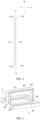
- a battery pack of the present application includes a temperature control component 1, a plurality of batteries 2, a lower box 3, an air duct component 4, a fan 5, a cable tie 6, an upper box cover 7, an end plate 8, an installation panel 9 and a wire harness isolation plate (not shown).
- the plurality of batteries 2 include a first battery 2A and a second battery 2B, and the temperature control component 1 is disposed between the first battery 2A and the second battery 2B. Further, there may be a plurality of first batteries 2A and a plurality of second batteries 2B, the first batteries 2A and the second batteries 2B are sequentially arranged alternately, and the temperature control component 1 may be disposed between each adjacent first battery 2A and second battery 2B in a longitudinal direction Y.
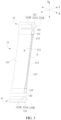
- the temperature control component 1 may include a temperature control tube 11, a first insulating member 12 and a second insulating member 13, where the first insulating member 12 and the second insulating member 13 are sleeved on two ends of the temperature control tube 11 in an up-down direction Z, respectively.
- the temperature control tube 11 is used for heat dissipation treatment for the batteries 2, and in order to ensure strength and thermal conductivity of the temperature control tube 11, the temperature control tube 11 may be made of a metal material, such as an aluminum profile.
- the temperature control tube 11 may include a first side wall 111, a second side wall 112, a partition wall 113, a first connection wall 114, and a second connection wall 115, where the first side wall 111, the second side wall 112, the partition wall 113, the first connection wall 114, and the second connection wall 115 may be integrally formed with an aluminum extrusion process.
- the first side wall 111 and the second side wall 112 are oppositely disposed in the longitudinal direction Y, and the second side wall 112 is connected to the first side wall 111 through the first connection wall 114 and the second connection wall 115, and thereby the first side wall 111, the second side wall 112, the first connection wall 114, and the second connection wall 115 together form a surrounding frame structure with a cavity.
- the first side wall 111 and the second side wall 112 are directly facing large surfaces of corresponding batteries 2. When external air flows through the cavity of the temperature control tube 11, heat dissipation treatment for the batteries 2 could be realized to ensure the temperature control component 1 meets the thermal management requirement for the batteries 2.
- At least part of an outer surface of the first side wall 111 is formed into a curved surface concaved toward the second side wall 112 in the longitudinal direction Y.
- the large surface of the battery 2 gradually bulges into the gap S and presses the outer surface of the first side wall 111, and since at least part of the outer surface of the first side wall 111 is formed into a curved surface, this curved surface structure increases a contact area between the first side wall 111 and the large surface of the corresponding battery 2, and could fit with a shape of the large surface of the corresponding battery 2 bulging out, and thus a force of the temperature control tube 11 on the battery 2 is effectively reduced, and service life of the battery 2 is thereby greatly improved.
- the first side wall 111 may include: a first main body portion 111A, formed into a curved surface concave toward the second side wall 112 in the longitudinal direction Y; a first extension portion 111B, connected to one end of the first main body portion 111A and extending in the up-down direction Z; and a third extension portion 111C, connected to the other end of the first main body portion 111A and extending in the up-down direction Z.
- the first main body portion 111A corresponds to a middle position of the corresponding battery 2
- the first extension portion 111B and the third extension portion 111C correspond to two end positions of the corresponding battery 2 in the up-down direction Z.
- the first extension portion 111B and the third extension portion 111C corresponding to the upper and lower ends of the battery 2 may be directly formed into a planar structure.
- At least part of an outer surface of the second side wall 112 is formed into a curved surface concaved toward the first side wall 111 in the longitudinal direction Y.
- the large surface of the battery 2 gradually bulges into the gap S and presses the outer surface of the second side wall 112, and since at least part of the outer surface of the second side wall 112 is formed into a curved surface, this curved surface structure increases a contact area between the second side wall 112 and the large surface of the corresponding battery 2 and could fit with a shape of the large surface of the corresponding battery 2 bulging out, and thus a force of the temperature control tube 11 on the battery 2 is effectively reduced, and service life of the battery 2 is thereby greatly improved.
- the second side wall 112 may include: a second main body portion 112A, formed into a curved surface concave toward the first side wall 111 in the longitudinal direction Y; a second extension portion 112B, connected to one end of the second main body portion 112A and extending in the up-down direction Z, and disposed opposite to the first extension portion 111B in the longitudinal direction Y; and a fourth extension portion 112C, connected to the other end of the second main body portion 112A and extending in the up-down direction Z, and disposed opposite to the third extension portion 111C in the longitudinal direction Y.
- the second main body portion 112A corresponds to a middle position of the corresponding battery 2
- the second extension portion 112B and the fourth extension portion 112C correspond to two end positions of the corresponding battery 2 in the up-down direction Z.
- the second extension portion 112B and the fourth extension portion 112C corresponding to the upper and lower ends of the battery 2 may be directly formed into a planar structure.
- a gap S is formed between the first side wall 111 and a corresponding battery 2, and between the second side wall 112 and a corresponding battery 2, respectively.
- the large surfaces of two adjacent batteries 2 (that is, the first battery 2A and the second battery 2B) respectively bulge into corresponding gaps S and press the first side wall 111 and the second side wall 112. Since the curved surface structure of the first side wall 111 could fit with a shape of the large surface of the corresponding battery 2 bulging out, and the curved surface structure of the second side wall 112 could also fit with a shape of the large surface of the corresponding battery 2 bulging out, therefore the forces of the temperature control tube 11 on the batteries 2 are effectively reduced, and the service life of the batteries 2 is thereby greatly improved.
- the partition wall 113 extends in the longitudinal direction Y and is connected to the first side wall 111 and the second side wall 112 to divide the cavity into a plurality of channels F.
- the arrangement of the partition wall 113 not only improves strength of the temperature control tube 11, but also ensures that the temperature control tube 11 has enough space for external air to circulate, so that the temperature control component 1 meets the thermal management requirement for the batteries 2.
- the first connection wall 114 is connected to an end of the first extension portion 111B away from the first main body portion 111A and an end of the second extension portion 112B away from the second main body portion 112A, and the first connection wall 114, the first extension portion 111B and the second extension portion 112B are accommodated in the first insulating member 12 together.
- the first connection wall 114 may be formed into a flat plate structure or a curved structure.
- the second connection wall 115 is connected to an end of the third extension portion 111C away from the first main body portion 111A and an end of the fourth extension portion 112C away from the second main body portion 112A, and the second connection wall 115, the third extension portion 111C and the fourth extension portion 112C are accommodated in the second insulating member 13 together.
- the second connection wall 115 may be formed into a flat plate structure or a curved structure.
- the first insulating member 12 is sleeved outside of the first extension portion 111B of the first side wall 111 and the second extension portion 112B of the second side wall 112, and is in direct contact with two adjacent batteries 2.
- the first insulating member 12 is made of an insulating buffer material.
- the first insulating member 12 may include: a first body portion 121; and a first opening groove 122, disposed on the first body portion 121, a groove depth direction of the first opening groove 122 is disposed in the up-down direction Z, and the first opening groove 122 is provided for insertion of the first extension portion 111B, the second extension portion 112B and the first connection wall 114.
- the first body portion 121 may include: a first upper wall 121A, located on one side of the first extension portion 111B and the second extension portion 112B in the up-down direction Z; and two first clamping walls 121B, clamping the first extension portion 111B and the second extension portion 112B in the longitudinal direction Y, each first clamping wall 121B is connected to the first upper wall 121A and extends in the up-down direction Z, and a thickness of each first clamping wall 121B gradually decreases in the up-down direction Z from the first upper wall 121A to a direction away from the first upper wall 121A.
- the second insulating member 13 is sleeved outside of the third extension portion 111C of the first side wall 111 and the fourth extension portion 112C of the second side wall 112, and is in direct contact with the two adjacent batteries 2.
- the second insulating member 13 is also made of an insulating buffer material.
- the second insulating member 13 may include: a second body portion 131; and a second opening groove 132, disposed on the second body portion 131, a groove depth direction of the second opening groove 132 is provided in the up-down direction Z, and the second opening groove 132 is provided for insertion of the third extension portion 111C, the fourth extension portion 112C and the second connection wall 115.
- the second body portion 131 may include: a second upper wall 131A, located on one side of the third extension portion 111C and the fourth extension portion 112C in the up-down direction Z; and two second clamping walls 131B, clamping the first extension portion 111C and the fourth extension portion 112C in the longitudinal direction Y, each second clamping wall 131B is connected to the second upper wall 131A and extends in the up-down direction Z, and a thickness of each second clamping wall 131B gradually decreases in the up-down direction Z from the second upper wall 131A to a direction away from the second upper wall 131A.
- the lower box 3 is used to support the plurality of batteries 2.
- the plurality of batteries 2 may be arranged in at least two rows of battery banks in a lateral direction X, and the air duct component 4 is disposed between the two rows of battery banks and fixed to the lower box 3.
- An air duct is formed between the air duct component 4 and a corresponding battery bank, and the air duct is in communication with the plurality of channels F of the corresponding temperature control component 1 and the fan 5.
- the air duct component 4 may include an air volume regulating plate 41, a first support plate 42, a second support plate 43, a mounting plate 44 and a sealing strip 45.
- the air volume regulating plate 41 is disposed within the air duct, the first support plate 42 is spaced apart from the second support plate 43 in the longitudinal direction Y, and the first support plate 42 is close to the fan 5.
- a height of the air volume regulating plate 41 decreases sequentially in a direction from the first support plate 42 to the second support plate 43, so that the air duct expands, from a side close to the fan 5 to a side away from the fan 5 in the longitudinal direction Y.
- the mounting plate 44 extends in the longitudinal direction Y and is connected to the first support plate 42 and the second support plate 43, and the air volume regulating plate 41 is fixedly mounted on the mounting plate 44.
- the sealing strip 45 is disposed on the first support plate 42, the second support plate 43 and the mounting plate 44. After the air duct component 4 is assembled with the plurality of batteries 2, the sealing strip 45 is adhered to a corresponding battery bank for a sealing connection with the battery bank.
- the end plate 8 is disposed at both ends of each battery bank in the longitudinal direction Y.
- the cable tie 6 tightly bundles, in the circumferential direction, all the batteries 2 in a corresponding battery bank, a corresponding temperature control component 1 and two corresponding end plates 8.
- the installation panel 9 is located outside of a corresponding end plate 8 in the longitudinal direction Y, is fixedly connected to the lower box 3 and the corresponding end plate 8, and is fixedly installed with the fan 5.
- the harness isolation plate is disposed above the plurality of batteries 2 and directly fixed to the end plate 8, thereby helping to improve grouping efficiency and an integration degree of the battery pack.
- the upper box cover 7 is disposed above the harness isolation plate and fixedly connected to the harness isolation plate through fasteners (such as rivets).
- fasteners such as rivets
Landscapes
- Chemical & Material Sciences (AREA)
- Chemical Kinetics & Catalysis (AREA)
- Electrochemistry (AREA)
- General Chemical & Material Sciences (AREA)
- Engineering & Computer Science (AREA)
- Manufacturing & Machinery (AREA)
- Secondary Cells (AREA)
- Battery Mounting, Suspending (AREA)
Claims (7)
- Batteriesatz, dadurch gekennzeichnet, dass er eine Vielzahl von Batterien (2) und eine Temperierungskomponente (1) umfasst, wobei die Vielzahl von Batterien (2) eine erste Batterie (2A) und eine zweite Batterie (2B) umfasst, die Temperierungskomponente (1) zwischen der ersten Batterie (2A) und der zweiten Batterie (2B) angeordnet ist, die Temperierungskomponente (1) eine Temperierungsröhre (11) umfasst und die Temperierungsröhre (11) Folgendes umfasst:eine erste Seitenwand (111);eine zweite Seitenwand (112), die in einer Längsrichtung (Y) der ersten Seitenwand (111) gegenüber angeordnet ist, und wobei die zweite Seitenwand (112) mit der ersten Seitenwand (111) verbunden ist und zusammen mit der ersten Seitenwand (111) einen Hohlraum bildet;wobei mindestens ein Teil einer Außenfläche der ersten Seitenwand (111) zu einer gekrümmten Fläche geformt ist, die in der Längsrichtung (Y) in Richtung der zweiten Seitenwand (112) gewölbt ist; undwobei mindestens ein Teil einer Außenfläche der zweiten Seitenwand (112) zu einer gekrümmten Fläche geformt ist, die in der Längsrichtung (Y) in Richtung der ersten Seitenwand (111) gewölbt ist;wobei die erste Seitenwand (111) Folgendes umfasst: einen ersten Hauptkörperabschnitt (111A), der zu einer gekrümmten Fläche geformt ist, die in der Längsrichtung (Y) in Richtung der zweiten Seitenwand (112) gewölbt ist; und einen ersten Verlängerungsabschnitt (111B), der mit einem Ende des ersten Hauptkörperabschnitts (111A) verbunden ist und sich in einer Aufwärts-Abwärts-Richtung (Z) erstreckt;wobei die zweite Seitenwand (112) Folgendes umfasst: einen zweiten Hauptkörperabschnitt (112A), der zu einer gekrümmten Fläche geformt ist, die in der Längsrichtung (Y) in Richtung der ersten Seitenwand (111) gewölbt ist; und einen zweiten Verlängerungsabschnitt (112B), der mit einem Ende des zweiten Hauptkörperabschnitts (112A) verbunden ist und sich in der Aufwärts-Abwärts-Richtung (Z) erstreckt, und wobei der zweite Verlängerungsabschnitt (112B) in der Längsrichtung (Y) dem ersten Verlängerungsabschnitt (111B) gegenüber angeordnet ist; unddadurch gekennzeichnet, dass die Temperierungskomponente (1) ferner Folgendes umfasst: ein erstes Isolierelement (12), das außen auf den ersten Verlängerungsabschnitt (111B) der ersten Seitenwand (111) und den zweiten Verlängerungsabschnitt (112B) der zweiten Seitenwand (112) aufgesteckt ist und sich mit der ersten Batterie (2A) und der zweiten Batterie (2B) in direktem Kontakt befindet.
- Batteriesatz nach Anspruch 1, dadurch gekennzeichnet, dass die Temperierungsröhre (11) ferner Folgendes umfasst: eine Trennwand (113), die sich in der Längsrichtung (Y) erstreckt und mit der ersten Seitenwand (111) und der zweiten Seitenwand (112) verbunden ist, um den Hohlraum in eine Vielzahl von Durchgängen (F) zu unterteilen.
- Batteriesatz nach Anspruch 1, dadurch gekennzeichnet, dass das erste Isolierelement (12) Folgendes umfasst: einen ersten Körperabschnitt (121); und eine erste Öffnungsnut (122), die an dem ersten Körperabschnitt (121) angeordnet ist, wobei eine Nuttiefenrichtung der ersten Öffnungsnut (122) in der Aufwärts-Abwärts-Richtung (Z) angeordnet ist und die erste Öffnungsnut (122) zum Einstecken des ersten Verlängerungsabschnitts (111B) und des zweiten Verlängerungsabschnitts (112B) vorgesehen ist.
- Batteriesatz nach Anspruch 3, dadurch gekennzeichnet, dass der erste Körperabschnitt (121) Folgendes umfasst: eine erste Deckwand (121A), die sich in der Aufwärts-Abwärts-Richtung (Z) auf einer Seite des ersten Verlängerungsabschnitts (111B) und des zweiten Verlängerungsabschnitts (112B) befindet; und zwei erste Klemmwände (121B), die den ersten Verlängerungsabschnitt (111B) und den zweiten Verlängerungsabschnitt (112B) in der Längsrichtung (Y) klemmen, wobei die zwei ersten Klemmwände (121B) jeweils mit der ersten Deckwand (121A) verbunden sind und sich in der Aufwärts-Abwärts-Richtung (Z) erstrecken, und wobei eine Dicke jeder ersten Klemmwand (121B) in der Aufwärts-Abwärts-Richtung (Z) von der ersten Deckwand (121A) zu einer Richtung weg von der ersten Deckwand (121A) allmählich abnimmt.
- Batteriesatz nach einem der Ansprüche 1 bis 4, dadurch gekennzeichnet, dassdie erste Seitenwand (111) ferner Folgendes umfasst: einen dritten Verlängerungsabschnitt (111C), der mit dem anderen Ende des ersten Hauptkörperabschnitts (111A) verbunden ist und sich in der Aufwärts-Abwärts-Richtung (Z) erstreckt;wobei die zweite Seitenwand (112) ferner Folgendes umfasst: einen vierten Verlängerungsabschnitt (112C), der mit dem anderen Ende des zweiten Hauptkörperabschnitts (112A) verbunden ist und sich in der Aufwärts-Abwärts-Richtung (Z) erstreckt, und wobei der vierte Verlängerungsabschnitt (112C) in der Längsrichtung (Y) dem dritten Verlängerungsabschnitt (111C) gegenüber angeordnet ist;wobei die Temperierungskomponente (1) ferner Folgendes umfasst: ein zweites Isolierelement (13), das außen auf den dritten Verlängerungsabschnitt (111C) und den vierten Verlängerungsabschnitt (112C) aufgesteckt ist.
- Batteriesatz nach Anspruch 5, dadurch gekennzeichnet, dass das zweite Isolierelement (13) Folgendes umfasst: einen zweiten Körperabschnitt (131); und eine zweite Öffnungsnut (132), die an dem zweiten Körperabschnitt (131) angeordnet ist, wobei eine Nuttiefenrichtung der zweiten Öffnungsnut (132) in der Aufwärts-Abwärts-Richtung (Z) angeordnet ist und die zweite Öffnungsnut (132) zum Einstecken des dritten Verlängerungsabschnitts (111C) und des vierten Verlängerungsabschnitts (112C) vorgesehen ist.
- Batteriesatz nach Anspruch 6, dadurch gekennzeichnet, dass der zweite Körperabschnitt (131) Folgendes umfasst: eine zweite Deckwand (131A), die sich in der Aufwärts-Abwärts-Richtung (Z) auf einer Seite des dritten Verlängerungsabschnitts (111C) und des vierten Verlängerungsabschnitts (112C) befindet; und zwei zweite Klemmwände (131B), die den dritten Verlängerungsabschnitt (111C) und den vierten Verlängerungsabschnitt (112C) in der Längsrichtung (Y) klemmen, wobei die zwei zweiten Klemmwände (131B) jeweils mit der zweiten Deckwand (131A) verbunden sind und sich in der Aufwärts-Abwärts-Richtung (Z) erstrecken, und wobei eine Dicke jeder zweiten Klemmwand (131B) in der Aufwärts-Abwärts-Richtung (Z) von der zweiten Deckwand (131A) zu einer Richtung weg von der zweiten Deckwand (131A) allmählich abnimmt.
Applications Claiming Priority (2)
| Application Number | Priority Date | Filing Date | Title |
|---|---|---|---|
| CN201920919814.3U CN210136909U (zh) | 2019-06-18 | 2019-06-18 | 温控组件及电池包 |
| PCT/CN2020/093512 WO2020253507A1 (zh) | 2019-06-18 | 2020-05-29 | 温控组件及电池包 |
Publications (3)
| Publication Number | Publication Date |
|---|---|
| EP3780146A1 EP3780146A1 (de) | 2021-02-17 |
| EP3780146A4 EP3780146A4 (de) | 2021-10-13 |
| EP3780146B1 true EP3780146B1 (de) | 2023-02-15 |
Family
ID=69706914
Family Applications (1)
| Application Number | Title | Priority Date | Filing Date |
|---|---|---|---|
| EP20775798.0A Active EP3780146B1 (de) | 2019-06-18 | 2020-05-29 | Temperaturregelungsanordnung und batteriepack |
Country Status (7)
| Country | Link |
|---|---|
| US (1) | US12206083B2 (de) |
| EP (1) | EP3780146B1 (de) |
| JP (1) | JP7410980B2 (de) |
| KR (1) | KR102740793B1 (de) |
| CN (1) | CN210136909U (de) |
| HU (1) | HUE061487T2 (de) |
| WO (1) | WO2020253507A1 (de) |
Families Citing this family (7)
| Publication number | Priority date | Publication date | Assignee | Title |
|---|---|---|---|---|
| CN112103419B (zh) * | 2019-06-18 | 2024-09-06 | 宁德时代新能源科技股份有限公司 | 温控组件及电池包 |
| CN210136909U (zh) * | 2019-06-18 | 2020-03-10 | 宁德时代新能源科技股份有限公司 | 温控组件及电池包 |
| CN114221074A (zh) * | 2020-09-07 | 2022-03-22 | 比亚迪股份有限公司 | 一种电池托盘、电池包及电动汽车 |
| CN115332669A (zh) * | 2021-01-15 | 2022-11-11 | 张芳群 | 基于侧壁空腔降温的电池 |
| EP4395013A4 (de) * | 2022-01-27 | 2025-01-22 | Contemporary Amperex Technology (Hong Kong) Limited | Batterie, stromverbrauchende vorrichtung, verfahren zur herstellung der batterie und vorrichtung zur herstellung der batterie |
| JP7616153B2 (ja) * | 2022-05-26 | 2025-01-17 | トヨタ自動車株式会社 | 電池パックおよび車両 |
| KR20240092366A (ko) * | 2022-12-14 | 2024-06-24 | 주식회사 엘지에너지솔루션 | 배터리 디바이스 |
Family Cites Families (14)
| Publication number | Priority date | Publication date | Assignee | Title |
|---|---|---|---|---|
| JPH07190661A (ja) * | 1993-12-27 | 1995-07-28 | Hitachi Ltd | 熱交換器 |
| CN1188889A (zh) | 1997-01-20 | 1998-07-29 | 株式会社杰克塞尔 | 热交换器用管 |
| JP2000048867A (ja) * | 1998-07-31 | 2000-02-18 | Toyota Motor Corp | 組電池 |
| DE10238235A1 (de) | 2002-08-21 | 2004-03-04 | Daimlerchrysler Ag | Elektrochemischer Energiespeicher mit Wärmeaustauscherstruktur und mehreren elektrochemischen Speicherzellen |
| EP1644682A1 (de) | 2003-07-15 | 2006-04-12 | Outokumpu Copper Products Oy | DRUCK STANDHALTENDES WûRME BERTRAGUNGSROHR UNDHERSTELLUNGSVERFAHREN DAF R |
| KR100590049B1 (ko) | 2004-11-30 | 2006-06-14 | 삼성에스디아이 주식회사 | 이차 전지 모듈과 이에 적용되는 단위 전지 고정용앤드플레이트 |
| DE102009048250A1 (de) | 2009-10-05 | 2011-04-07 | Li-Tec Battery Gmbh | Batterieanordnung |
| US9065158B2 (en) * | 2010-05-28 | 2015-06-23 | GM Global Technology Operations LLC | Corrugated fin and frame assembly for battery cooling |
| JP2015011919A (ja) * | 2013-07-01 | 2015-01-19 | 三洋電機株式会社 | 電源装置 |
| US9640788B2 (en) | 2014-08-22 | 2017-05-02 | Ford Global Technologies, Llc | Battery cell separator having contoured profile |
| JP2016152203A (ja) * | 2015-02-19 | 2016-08-22 | 日立オートモティブシステムズ株式会社 | 組電池 |
| JP6853947B2 (ja) | 2016-11-15 | 2021-04-07 | 株式会社Gsユアサ | 蓄電装置 |
| KR102244139B1 (ko) | 2017-07-31 | 2021-04-22 | 주식회사 엘지화학 | 배터리 셀용 카트리지 및 이를 포함하는 배터리 모듈 |
| CN210136909U (zh) | 2019-06-18 | 2020-03-10 | 宁德时代新能源科技股份有限公司 | 温控组件及电池包 |
-
2019
- 2019-06-18 CN CN201920919814.3U patent/CN210136909U/zh active Active
-
2020
- 2020-05-29 WO PCT/CN2020/093512 patent/WO2020253507A1/zh not_active Ceased
- 2020-05-29 US US17/044,485 patent/US12206083B2/en active Active
- 2020-05-29 JP JP2021568932A patent/JP7410980B2/ja active Active
- 2020-05-29 KR KR1020217035970A patent/KR102740793B1/ko active Active
- 2020-05-29 EP EP20775798.0A patent/EP3780146B1/de active Active
- 2020-05-29 HU HUE20775798A patent/HUE061487T2/hu unknown
Also Published As
| Publication number | Publication date |
|---|---|
| JP2022537098A (ja) | 2022-08-24 |
| KR20210149139A (ko) | 2021-12-08 |
| KR102740793B1 (ko) | 2024-12-10 |
| US12206083B2 (en) | 2025-01-21 |
| US20230163381A1 (en) | 2023-05-25 |
| JP7410980B2 (ja) | 2024-01-10 |
| EP3780146A4 (de) | 2021-10-13 |
| HUE061487T2 (hu) | 2023-07-28 |
| WO2020253507A1 (zh) | 2020-12-24 |
| EP3780146A1 (de) | 2021-02-17 |
| CN210136909U (zh) | 2020-03-10 |
Similar Documents
| Publication | Publication Date | Title |
|---|---|---|
| EP3780146B1 (de) | Temperaturregelungsanordnung und batteriepack | |
| US11936026B2 (en) | Temperature control component and battery pack | |
| JP7412457B2 (ja) | 温度制御アセンブリ及び電池パック | |
| US8492019B2 (en) | Extruded thermal fin for temperature control of battery cells | |
| JP2022536884A5 (de) | ||
| US20110104545A1 (en) | Battery, Particularly for a Hybrid Drive | |
| CN210136906U (zh) | 温控组件及电池包 | |
| CN210136907U (zh) | 温控组件及电池包 | |
| JP2000048867A (ja) | 組電池 | |
| CN112103418B (zh) | 温控组件及电池包 | |
| CN112103419A (zh) | 温控组件及电池包 | |
| CN118943615A (zh) | 电池包 | |
| CN211376748U (zh) | 温控组件及电池包 | |
| CN116666812A (zh) | 冷却板、电池包和用电设备 | |
| EP4583250A1 (de) | Batteriemodul, kühlplatte und batteriepack | |
| CN118970338B (zh) | 电池箱体 | |
| CN222940005U (zh) | 电池包冷却结构、电池包及车辆 | |
| US20240339651A1 (en) | Cell separation element with swelling adjustment and battery module for a motor vehicle | |
| WO2026031392A1 (zh) | 一种液冷板 | |
| WO2024244855A1 (zh) | 冷却板、电池包和用电设备 |
Legal Events
| Date | Code | Title | Description |
|---|---|---|---|
| STAA | Information on the status of an ep patent application or granted ep patent |
Free format text: STATUS: UNKNOWN |
|
| STAA | Information on the status of an ep patent application or granted ep patent |
Free format text: STATUS: THE INTERNATIONAL PUBLICATION HAS BEEN MADE |
|
| PUAI | Public reference made under article 153(3) epc to a published international application that has entered the european phase |
Free format text: ORIGINAL CODE: 0009012 |
|
| STAA | Information on the status of an ep patent application or granted ep patent |
Free format text: STATUS: REQUEST FOR EXAMINATION WAS MADE |
|
| 17P | Request for examination filed |
Effective date: 20201001 |
|
| AK | Designated contracting states |
Kind code of ref document: A1 Designated state(s): AL AT BE BG CH CY CZ DE DK EE ES FI FR GB GR HR HU IE IS IT LI LT LU LV MC MK MT NL NO PL PT RO RS SE SI SK SM TR |
|
| AX | Request for extension of the european patent |
Extension state: BA ME |
|
| REG | Reference to a national code |
Ref country code: DE Ref legal event code: R079 Ref document number: 602020008136 Country of ref document: DE Free format text: PREVIOUS MAIN CLASS: H01M0002100000 Ipc: H01M0010613000 |
|
| A4 | Supplementary search report drawn up and despatched |
Effective date: 20210908 |
|
| RIC1 | Information provided on ipc code assigned before grant |
Ipc: H01M 50/209 20210101ALI20210903BHEP Ipc: H01M 10/6557 20140101ALI20210903BHEP Ipc: H01M 10/647 20140101ALI20210903BHEP Ipc: H01M 10/613 20140101AFI20210903BHEP |
|
| RAP3 | Party data changed (applicant data changed or rights of an application transferred) |
Owner name: CONTEMPORARY AMPEREX TECHNOLOGY CO., LIMITED |
|
| STAA | Information on the status of an ep patent application or granted ep patent |
Free format text: STATUS: EXAMINATION IS IN PROGRESS |
|
| 17Q | First examination report despatched |
Effective date: 20220503 |
|
| DAV | Request for validation of the european patent (deleted) | ||
| DAX | Request for extension of the european patent (deleted) | ||
| GRAP | Despatch of communication of intention to grant a patent |
Free format text: ORIGINAL CODE: EPIDOSNIGR1 |
|
| STAA | Information on the status of an ep patent application or granted ep patent |
Free format text: STATUS: GRANT OF PATENT IS INTENDED |
|
| INTG | Intention to grant announced |
Effective date: 20221115 |
|
| GRAS | Grant fee paid |
Free format text: ORIGINAL CODE: EPIDOSNIGR3 |
|
| GRAA | (expected) grant |
Free format text: ORIGINAL CODE: 0009210 |
|
| STAA | Information on the status of an ep patent application or granted ep patent |
Free format text: STATUS: THE PATENT HAS BEEN GRANTED |
|
| AK | Designated contracting states |
Kind code of ref document: B1 Designated state(s): AL AT BE BG CH CY CZ DE DK EE ES FI FR GB GR HR HU IE IS IT LI LT LU LV MC MK MT NL NO PL PT RO RS SE SI SK SM TR |
|
| REG | Reference to a national code |
Ref country code: CH Ref legal event code: EP Ref country code: GB Ref legal event code: FG4D |
|
| REG | Reference to a national code |
Ref country code: DE Ref legal event code: R096 Ref document number: 602020008136 Country of ref document: DE |
|
| REG | Reference to a national code |
Ref country code: AT Ref legal event code: REF Ref document number: 1548714 Country of ref document: AT Kind code of ref document: T Effective date: 20230315 Ref country code: IE Ref legal event code: FG4D |
|
| REG | Reference to a national code |
Ref country code: SE Ref legal event code: TRGR |
|
| REG | Reference to a national code |
Ref country code: LT Ref legal event code: MG9D |
|
| P01 | Opt-out of the competence of the unified patent court (upc) registered |
Effective date: 20230516 |
|
| REG | Reference to a national code |
Ref country code: NL Ref legal event code: MP Effective date: 20230215 |
|
| REG | Reference to a national code |
Ref country code: AT Ref legal event code: MK05 Ref document number: 1548714 Country of ref document: AT Kind code of ref document: T Effective date: 20230215 |
|
| REG | Reference to a national code |
Ref country code: HU Ref legal event code: AG4A Ref document number: E061487 Country of ref document: HU |
|
| PG25 | Lapsed in a contracting state [announced via postgrant information from national office to epo] |
Ref country code: RS Free format text: LAPSE BECAUSE OF FAILURE TO SUBMIT A TRANSLATION OF THE DESCRIPTION OR TO PAY THE FEE WITHIN THE PRESCRIBED TIME-LIMIT Effective date: 20230215 Ref country code: PT Free format text: LAPSE BECAUSE OF FAILURE TO SUBMIT A TRANSLATION OF THE DESCRIPTION OR TO PAY THE FEE WITHIN THE PRESCRIBED TIME-LIMIT Effective date: 20230615 Ref country code: NO Free format text: LAPSE BECAUSE OF FAILURE TO SUBMIT A TRANSLATION OF THE DESCRIPTION OR TO PAY THE FEE WITHIN THE PRESCRIBED TIME-LIMIT Effective date: 20230515 Ref country code: NL Free format text: LAPSE BECAUSE OF FAILURE TO SUBMIT A TRANSLATION OF THE DESCRIPTION OR TO PAY THE FEE WITHIN THE PRESCRIBED TIME-LIMIT Effective date: 20230215 Ref country code: LV Free format text: LAPSE BECAUSE OF FAILURE TO SUBMIT A TRANSLATION OF THE DESCRIPTION OR TO PAY THE FEE WITHIN THE PRESCRIBED TIME-LIMIT Effective date: 20230215 Ref country code: LT Free format text: LAPSE BECAUSE OF FAILURE TO SUBMIT A TRANSLATION OF THE DESCRIPTION OR TO PAY THE FEE WITHIN THE PRESCRIBED TIME-LIMIT Effective date: 20230215 Ref country code: HR Free format text: LAPSE BECAUSE OF FAILURE TO SUBMIT A TRANSLATION OF THE DESCRIPTION OR TO PAY THE FEE WITHIN THE PRESCRIBED TIME-LIMIT Effective date: 20230215 Ref country code: ES Free format text: LAPSE BECAUSE OF FAILURE TO SUBMIT A TRANSLATION OF THE DESCRIPTION OR TO PAY THE FEE WITHIN THE PRESCRIBED TIME-LIMIT Effective date: 20230215 Ref country code: AT Free format text: LAPSE BECAUSE OF FAILURE TO SUBMIT A TRANSLATION OF THE DESCRIPTION OR TO PAY THE FEE WITHIN THE PRESCRIBED TIME-LIMIT Effective date: 20230215 |
|
| PG25 | Lapsed in a contracting state [announced via postgrant information from national office to epo] |
Ref country code: PL Free format text: LAPSE BECAUSE OF FAILURE TO SUBMIT A TRANSLATION OF THE DESCRIPTION OR TO PAY THE FEE WITHIN THE PRESCRIBED TIME-LIMIT Effective date: 20230215 Ref country code: IS Free format text: LAPSE BECAUSE OF FAILURE TO SUBMIT A TRANSLATION OF THE DESCRIPTION OR TO PAY THE FEE WITHIN THE PRESCRIBED TIME-LIMIT Effective date: 20230615 Ref country code: GR Free format text: LAPSE BECAUSE OF FAILURE TO SUBMIT A TRANSLATION OF THE DESCRIPTION OR TO PAY THE FEE WITHIN THE PRESCRIBED TIME-LIMIT Effective date: 20230516 Ref country code: FI Free format text: LAPSE BECAUSE OF FAILURE TO SUBMIT A TRANSLATION OF THE DESCRIPTION OR TO PAY THE FEE WITHIN THE PRESCRIBED TIME-LIMIT Effective date: 20230215 |
|
| PG25 | Lapsed in a contracting state [announced via postgrant information from national office to epo] |
Ref country code: SM Free format text: LAPSE BECAUSE OF FAILURE TO SUBMIT A TRANSLATION OF THE DESCRIPTION OR TO PAY THE FEE WITHIN THE PRESCRIBED TIME-LIMIT Effective date: 20230215 Ref country code: RO Free format text: LAPSE BECAUSE OF FAILURE TO SUBMIT A TRANSLATION OF THE DESCRIPTION OR TO PAY THE FEE WITHIN THE PRESCRIBED TIME-LIMIT Effective date: 20230215 Ref country code: EE Free format text: LAPSE BECAUSE OF FAILURE TO SUBMIT A TRANSLATION OF THE DESCRIPTION OR TO PAY THE FEE WITHIN THE PRESCRIBED TIME-LIMIT Effective date: 20230215 Ref country code: DK Free format text: LAPSE BECAUSE OF FAILURE TO SUBMIT A TRANSLATION OF THE DESCRIPTION OR TO PAY THE FEE WITHIN THE PRESCRIBED TIME-LIMIT Effective date: 20230215 Ref country code: CZ Free format text: LAPSE BECAUSE OF FAILURE TO SUBMIT A TRANSLATION OF THE DESCRIPTION OR TO PAY THE FEE WITHIN THE PRESCRIBED TIME-LIMIT Effective date: 20230215 |
|
| REG | Reference to a national code |
Ref country code: DE Ref legal event code: R097 Ref document number: 602020008136 Country of ref document: DE |
|
| PG25 | Lapsed in a contracting state [announced via postgrant information from national office to epo] |
Ref country code: SK Free format text: LAPSE BECAUSE OF FAILURE TO SUBMIT A TRANSLATION OF THE DESCRIPTION OR TO PAY THE FEE WITHIN THE PRESCRIBED TIME-LIMIT Effective date: 20230215 |
|
| PLBE | No opposition filed within time limit |
Free format text: ORIGINAL CODE: 0009261 |
|
| STAA | Information on the status of an ep patent application or granted ep patent |
Free format text: STATUS: NO OPPOSITION FILED WITHIN TIME LIMIT |
|
| REG | Reference to a national code |
Ref country code: CH Ref legal event code: PL |
|
| PG25 | Lapsed in a contracting state [announced via postgrant information from national office to epo] |
Ref country code: MC Free format text: LAPSE BECAUSE OF FAILURE TO SUBMIT A TRANSLATION OF THE DESCRIPTION OR TO PAY THE FEE WITHIN THE PRESCRIBED TIME-LIMIT Effective date: 20230215 |
|
| 26N | No opposition filed |
Effective date: 20231116 |
|
| REG | Reference to a national code |
Ref country code: BE Ref legal event code: MM Effective date: 20230531 |
|
| PG25 | Lapsed in a contracting state [announced via postgrant information from national office to epo] |
Ref country code: SI Free format text: LAPSE BECAUSE OF FAILURE TO SUBMIT A TRANSLATION OF THE DESCRIPTION OR TO PAY THE FEE WITHIN THE PRESCRIBED TIME-LIMIT Effective date: 20230215 Ref country code: MC Free format text: LAPSE BECAUSE OF FAILURE TO SUBMIT A TRANSLATION OF THE DESCRIPTION OR TO PAY THE FEE WITHIN THE PRESCRIBED TIME-LIMIT Effective date: 20230215 Ref country code: LU Free format text: LAPSE BECAUSE OF NON-PAYMENT OF DUE FEES Effective date: 20230529 Ref country code: CH Free format text: LAPSE BECAUSE OF NON-PAYMENT OF DUE FEES Effective date: 20230531 Ref country code: LI Free format text: LAPSE BECAUSE OF NON-PAYMENT OF DUE FEES Effective date: 20230531 |
|
| REG | Reference to a national code |
Ref country code: IE Ref legal event code: MM4A |
|
| PG25 | Lapsed in a contracting state [announced via postgrant information from national office to epo] |
Ref country code: IE Free format text: LAPSE BECAUSE OF NON-PAYMENT OF DUE FEES Effective date: 20230529 |
|
| PG25 | Lapsed in a contracting state [announced via postgrant information from national office to epo] |
Ref country code: IE Free format text: LAPSE BECAUSE OF NON-PAYMENT OF DUE FEES Effective date: 20230529 |
|
| PG25 | Lapsed in a contracting state [announced via postgrant information from national office to epo] |
Ref country code: BE Free format text: LAPSE BECAUSE OF NON-PAYMENT OF DUE FEES Effective date: 20230531 |
|
| REG | Reference to a national code |
Ref country code: DE Ref legal event code: R081 Ref document number: 602020008136 Country of ref document: DE Owner name: CONTEMPORARY AMPEREX TECHNOLOGY (HONG KONG) LI, HK Free format text: FORMER OWNER: CONTEMPORARY AMPEREX TECHNOLOGY CO., LIMITED, NINGDE, FUJIAN, CN |
|
| REG | Reference to a national code |
Ref country code: GB Ref legal event code: 732E Free format text: REGISTERED BETWEEN 20240822 AND 20240828 |
|
| REG | Reference to a national code |
Ref country code: HU Ref legal event code: GB9C Owner name: CONTEMPORARY AMPEREX TECHNOLOGY (HONG KONG) LIMITED, HK Free format text: FORMER OWNER(S): CONTEMPORARY AMPEREX TECHNOLOGY CO., LIMITED, CN Ref country code: HU Ref legal event code: FH1C Free format text: FORMER REPRESENTATIVE(S): SBGK SZABADALMI UEGYVIVOEI IRODA, HU Representative=s name: DANUBIA SZABADALMI ES JOGI IRODA KFT., HU |
|
| PG25 | Lapsed in a contracting state [announced via postgrant information from national office to epo] |
Ref country code: BG Free format text: LAPSE BECAUSE OF FAILURE TO SUBMIT A TRANSLATION OF THE DESCRIPTION OR TO PAY THE FEE WITHIN THE PRESCRIBED TIME-LIMIT Effective date: 20230215 |
|
| PG25 | Lapsed in a contracting state [announced via postgrant information from national office to epo] |
Ref country code: BG Free format text: LAPSE BECAUSE OF FAILURE TO SUBMIT A TRANSLATION OF THE DESCRIPTION OR TO PAY THE FEE WITHIN THE PRESCRIBED TIME-LIMIT Effective date: 20230215 |
|
| PGFP | Annual fee paid to national office [announced via postgrant information from national office to epo] |
Ref country code: SE Payment date: 20250310 Year of fee payment: 6 |
|
| PGFP | Annual fee paid to national office [announced via postgrant information from national office to epo] |
Ref country code: DE Payment date: 20250402 Year of fee payment: 6 |
|
| PGFP | Annual fee paid to national office [announced via postgrant information from national office to epo] |
Ref country code: HU Payment date: 20250429 Year of fee payment: 6 |
|
| PGFP | Annual fee paid to national office [announced via postgrant information from national office to epo] |
Ref country code: IT Payment date: 20250422 Year of fee payment: 6 |
|
| PGFP | Annual fee paid to national office [announced via postgrant information from national office to epo] |
Ref country code: FR Payment date: 20250401 Year of fee payment: 6 |
|
| PG25 | Lapsed in a contracting state [announced via postgrant information from national office to epo] |
Ref country code: CY Free format text: LAPSE BECAUSE OF FAILURE TO SUBMIT A TRANSLATION OF THE DESCRIPTION OR TO PAY THE FEE WITHIN THE PRESCRIBED TIME-LIMIT; INVALID AB INITIO Effective date: 20200529 |
|
| PG25 | Lapsed in a contracting state [announced via postgrant information from national office to epo] |
Ref country code: TR Free format text: LAPSE BECAUSE OF FAILURE TO SUBMIT A TRANSLATION OF THE DESCRIPTION OR TO PAY THE FEE WITHIN THE PRESCRIBED TIME-LIMIT Effective date: 20230215 |
|
| PGFP | Annual fee paid to national office [announced via postgrant information from national office to epo] |
Ref country code: GB Payment date: 20260310 Year of fee payment: 7 |