EP3779744B1 - Informationsverarbeitungseinrichtung, steuerungsverfahren dafür, programm und informationsverarbeitungssystem - Google Patents
Informationsverarbeitungseinrichtung, steuerungsverfahren dafür, programm und informationsverarbeitungssystem Download PDFInfo
- Publication number
- EP3779744B1 EP3779744B1 EP20200215.0A EP20200215A EP3779744B1 EP 3779744 B1 EP3779744 B1 EP 3779744B1 EP 20200215 A EP20200215 A EP 20200215A EP 3779744 B1 EP3779744 B1 EP 3779744B1
- Authority
- EP
- European Patent Office
- Prior art keywords
- domain
- image reading
- web
- information processing
- information
- Prior art date
- Legal status (The legal status is an assumption and is not a legal conclusion. Google has not performed a legal analysis and makes no representation as to the accuracy of the status listed.)
- Active
Links
Images







Classifications
-
- G—PHYSICS
- G06—COMPUTING OR CALCULATING; COUNTING
- G06F—ELECTRIC DIGITAL DATA PROCESSING
- G06F3/00—Input arrangements for transferring data to be processed into a form capable of being handled by the computer; Output arrangements for transferring data from processing unit to output unit, e.g. interface arrangements
- G06F3/12—Digital output to print unit, e.g. line printer, chain printer
- G06F3/1201—Dedicated interfaces to print systems
- G06F3/1223—Dedicated interfaces to print systems specifically adapted to use a particular technique
- G06F3/1229—Printer resources management or printer maintenance, e.g. device status, power levels
- G06F3/1232—Transmitting printer device capabilities, e.g. upon request or periodically
-
- G—PHYSICS
- G06—COMPUTING OR CALCULATING; COUNTING
- G06F—ELECTRIC DIGITAL DATA PROCESSING
- G06F21/00—Security arrangements for protecting computers, components thereof, programs or data against unauthorised activity
- G06F21/60—Protecting data
- G06F21/604—Tools and structures for managing or administering access control systems
-
- G—PHYSICS
- G06—COMPUTING OR CALCULATING; COUNTING
- G06F—ELECTRIC DIGITAL DATA PROCESSING
- G06F13/00—Interconnection of, or transfer of information or other signals between, memories, input/output devices or central processing units
-
- G—PHYSICS
- G06—COMPUTING OR CALCULATING; COUNTING
- G06F—ELECTRIC DIGITAL DATA PROCESSING
- G06F21/00—Security arrangements for protecting computers, components thereof, programs or data against unauthorised activity
- G06F21/30—Authentication, i.e. establishing the identity or authorisation of security principals
- G06F21/44—Program or device authentication
-
- G—PHYSICS
- G06—COMPUTING OR CALCULATING; COUNTING
- G06F—ELECTRIC DIGITAL DATA PROCESSING
- G06F21/00—Security arrangements for protecting computers, components thereof, programs or data against unauthorised activity
- G06F21/60—Protecting data
- G06F21/62—Protecting access to data via a platform, e.g. using keys or access control rules
-
- G—PHYSICS
- G06—COMPUTING OR CALCULATING; COUNTING
- G06F—ELECTRIC DIGITAL DATA PROCESSING
- G06F3/00—Input arrangements for transferring data to be processed into a form capable of being handled by the computer; Output arrangements for transferring data from processing unit to output unit, e.g. interface arrangements
- G06F3/12—Digital output to print unit, e.g. line printer, chain printer
- G06F3/1201—Dedicated interfaces to print systems
- G06F3/1202—Dedicated interfaces to print systems specifically adapted to achieve a particular effect
- G06F3/1203—Improving or facilitating administration, e.g. print management
-
- G—PHYSICS
- G06—COMPUTING OR CALCULATING; COUNTING
- G06F—ELECTRIC DIGITAL DATA PROCESSING
- G06F3/00—Input arrangements for transferring data to be processed into a form capable of being handled by the computer; Output arrangements for transferring data from processing unit to output unit, e.g. interface arrangements
- G06F3/12—Digital output to print unit, e.g. line printer, chain printer
- G06F3/1201—Dedicated interfaces to print systems
- G06F3/1223—Dedicated interfaces to print systems specifically adapted to use a particular technique
- G06F3/1224—Client or server resources management
- G06F3/1227—Printer definition files
-
- G—PHYSICS
- G06—COMPUTING OR CALCULATING; COUNTING
- G06F—ELECTRIC DIGITAL DATA PROCESSING
- G06F3/00—Input arrangements for transferring data to be processed into a form capable of being handled by the computer; Output arrangements for transferring data from processing unit to output unit, e.g. interface arrangements
- G06F3/12—Digital output to print unit, e.g. line printer, chain printer
- G06F3/1201—Dedicated interfaces to print systems
- G06F3/1223—Dedicated interfaces to print systems specifically adapted to use a particular technique
- G06F3/1229—Printer resources management or printer maintenance, e.g. device status, power levels
- G06F3/1231—Device related settings, e.g. IP address, Name, Identification
-
- G—PHYSICS
- G06—COMPUTING OR CALCULATING; COUNTING
- G06F—ELECTRIC DIGITAL DATA PROCESSING
- G06F3/00—Input arrangements for transferring data to be processed into a form capable of being handled by the computer; Output arrangements for transferring data from processing unit to output unit, e.g. interface arrangements
- G06F3/12—Digital output to print unit, e.g. line printer, chain printer
- G06F3/1201—Dedicated interfaces to print systems
- G06F3/1223—Dedicated interfaces to print systems specifically adapted to use a particular technique
- G06F3/1236—Connection management
-
- H—ELECTRICITY
- H04—ELECTRIC COMMUNICATION TECHNIQUE
- H04L—TRANSMISSION OF DIGITAL INFORMATION, e.g. TELEGRAPHIC COMMUNICATION
- H04L67/00—Network arrangements or protocols for supporting network services or applications
- H04L67/50—Network services
- H04L67/535—Tracking the activity of the user
-
- H—ELECTRICITY
- H04—ELECTRIC COMMUNICATION TECHNIQUE
- H04N—PICTORIAL COMMUNICATION, e.g. TELEVISION
- H04N1/00—Scanning, transmission or reproduction of documents or the like, e.g. facsimile transmission; Details thereof
Definitions
- the present invention relates to an information processing apparatus, a control method therefor, a program, and an information processing system.
- patent literature 1 enables image reading via a web browser
- a web storage system in which read images are to be stored may reside in a domain different from the domain of a web application service providing system (cross domain).
- various web browsers serving as an operational environment for web applications implement a function of prohibiting JavaScript (R) included in a web application from obtaining data by transmitting a request to domains other than a domain in which the web application resides (prohibition of cross-domain requests).
- R JavaScript
- patent literature 1 describes a method of obtaining data using JSONP (JavaScript (R) Object Notation with Padding: a mechanism of obtaining cross-domain data using a script tag).
- JSONP JavaScript (R) Object Notation with Padding: a mechanism of obtaining cross-domain data using a script tag.
- this mechanism is inappropriate as a format for handling sensitive information because a server's endpoint is always exposed.
- XMLHttpRequest Level 2 Another measure for the cross-domain request prohibition function is XMLHttpRequest Level 2, which is specifications allowing cross-domain requests.
- CORS Cross-Origin Resource Sharing
- a web storage service i.e., a destination server
- CORS Cross-Origin Resource Sharing
- the present invention has been made in the light of the above problems, and an object thereof is to enable highly secure and user-convenient cross-domain communications.
- a user terminal (an information processing apparatus) 200, a web application service providing system 300, and a web storage system 400 (an external apparatus) are interconnected via a network 500 such as the Internet or an intranet.
- a network 500 such as the Internet or an intranet.
- multiple user terminals 200, web application service providing systems 300, and web storage systems 400 may be interconnected.
- domain A denotes the domain of the web application service providing system 300 and a browser 201
- domain B denotes the domain of the web storage system 400
- domain C denotes the domain of a Scan Server 202, as an example.
- An image reading apparatus (a device apparatus) 100 is connected to the user terminal 200.
- the connection to the user terminal 200 may be made with wired communication (e.g., a USB cable) as well as wireless communication.
- the image reading apparatus 100 may also be incorporated in the user terminal 200.
- the device apparatus may be an imaging apparatus (e.g., a camera), an image forming apparatus (e.g., a multifunction peripheral), an electric appliance (e.g., a refrigerator), a sensor (e.g., a thermometer), or an automobile.
- an imaging apparatus shot image information or audio information will be transmitted.
- an electric appliance information about the state of the electric appliance itself will be transmitted.
- a sensor information sensable by the sensor will be transmitted.
- information such as the mileage or location will be transmitted.
- FIG 1 is a schematic diagram of the image reading apparatus 100 according to an embodiment.
- the image reading apparatus 100 is an apparatus that transports one or more carrier media S stacked on a placement table 1 into the apparatus one by one along a path RT to read their images and ejects the carrier media S onto an ejection tray 2.
- the carrier media S to be read are sheets of OA paper, checks, vouchers, or cards, and the sheets may be thick or thin. Examples of cards may include insurance cards, drivers' licenses, and credit cards.
- the carrier media S also include books such as passports.
- a first transport unit 10 is provided as a feeding mechanism for feeding the carrier media S along the path RT.
- the first transport unit 10 includes a feed roller 11 and a separation roller 12 disposed opposite the feed roller 11, and successively transports the carrier media S on the placement table 1 one by one in a transport direction D1.
- Driving forces are transmitted to the feed roller 11 from a driving unit 3 such as a motor via a transmission unit 5, so that the feed roller 11 is rotationally driven in a direction indicated by an arrow in the figure (the forward direction to transport the carrier media S along the path RT).
- the transmission unit 5, which is an electromagnetic clutch for example, transmits and shuts off driving forces from the driving unit 3 to the feed roller 11.
- the transmission unit 5 connecting the driving unit 3 and the feed roller 11 transmits driving forces in normal mode, and shuts off driving forces in reversely transporting the carrier media S.
- the feed roller 11 becomes freely rotatable.
- the transmission unit 5 as above need not be provided if the feed roller 11 is driven only in one direction.
- the separation roller 12 disposed opposite the feed roller 11 is a roller for separating each carrier medium S and is in pressure-contact with the feed roller 11 at a constant pressure. To maintain this pressure-contact state, the separation roller 12 is swingably provided and configured to be biased toward the feed roller 11. Driving forces are transmitted to the separation roller 12 from the driving unit 3 via a torque limiter 12a, so that the separation roller 12 is rotationally driven in a direction indicated by a solid arrow (the direction opposite the forward direction of the feed roller 11).
- the separation roller 12 Since the transmission of driving forces to the separation roller 12 is restricted by the torque limiter 12a, the separation roller 12 rotates in a direction dragged by the feed roller 11 (the direction indicated by a dashed arrow) while in contact with the feed roller 11. Therefore, when multiple carrier media S are transported to the pressure-contact point between the feed roller 11 and the separation roller 12, the carrier media S except one of them are blocked so as not to be transported downstream.
- the separation roller 12 and the feed roller 11 form a separation mechanism in this embodiment, such a separation mechanism may not be necessarily provided. Rather, the feeding mechanism may simply successively feed the carrier media S one by one to the path RT. If the separation mechanism is provided, a separation pad that applies friction to the carrier media S may be disposed in pressure-contact with the feed roller 11, instead of a component like the separation roller 121, thereby realizing a similar separation function.
- a second transport unit 20 is a transport mechanism downstream in the transport direction from the first transport unit 10.
- the second transport unit 20 includes a driving roller 21 and a driven roller 22 driven by the driving roller 21, and transports the carrier media S transported from the first transport unit 10 downstream.
- Driving forces are transmitted to the driving roller 21 from a driving unit 4 such as a motor, so that the driving roller 21 is rotationally driven in a direction indicated by an arrow in the figure.
- the driven roller 22 is in pressure-contact with the driving roller 21 at a constant pressure and dragged by the driving roller 21.
- the driven roller 22 may be biased toward the driving roller 21 by a biasing unit (not shown) such as a spring.
- a third transport unit 30 resides downstream in the transport direction from the second transport unit 20.
- the third transport unit 30 includes a driving roller 31 and a driven roller 32 driven by the driving roller 31, and transports the carrier media S transported from the second transport unit 20 onto the ejection tray 2. That is, the third transport unit 30 functions as an ejection mechanism.
- Driving forces are transmitted to the driving roller 31 from the driving unit 4 such as a motor, so that the driving roller 31 is rotationally driven in a direction indicated by an arrow in the figure.
- the driven roller 32 is in pressure-contact with the driving roller 31 at a constant pressure and dragged by the driving roller 31.
- the driven roller 32 may be biased toward the driving roller 31 by a biasing unit (not shown) such as a spring.
- image reading units 70 disposed between the second transport unit 20 and the third transport unit 30 reads images, so that the second transport unit 20 and the third transport unit 30 transport the carrier media S at a constant speed. Keeping the transport speed not below the transport speed of the first transport unit 10 can ensure avoidance of a situation in which the following carrier medium S catches up with the preceding carrier medium S. For example, in this embodiment, the speed of the carrier media S transported by the second transport unit 20 and the third transport unit 30 is controlled to be above the speed of the carrier media S transported by the first transport unit 10.
- a minimum required interval can still be provided between the preceding carrier medium S and the following carrier medium S by controlling the driving unit 3 to intermittently delay the start of feeding the following carrier medium S.
- a multi-feed detection sensor 40 disposed between the first transport unit 10 and the second transport unit 20 is an example of a detection sensor for detecting that several carrier media S (such as paper) sticking together have passed through the first transport unit 10 due to e.g., static electricity (i.e., multi-feed in which the media are transported in layers) (a sensor for detecting the behavior and state of the sheets). While various types of sensors are available as the multi-feed detection sensor 40, it is an ultrasonic sensor in this embodiment and includes an ultrasonic transmission unit 41 and a corresponding reception unit 42.
- the multi-feed detection sensor 40 detects multi-feed based on a principle that the carrier media S such as paper involve different amounts of attenuation of ultrasound passing therethrough in the cases where the carrier media S are transported in layers and where they are transported one by one.
- a medium detection sensor 50 disposed downstream in the transport direction from the multi-feed detection sensor 40, is an example of an upstream detection sensor disposed upstream from the second transport unit 20 and downstream from the first transport unit 10 (a sensor for detecting the behavior and state of the sheets).
- the medium detection sensor 50 detects the position of each carrier medium S transported by the first transport unit 10, or more specifically, whether or not an edge of the carrier medium S has reached or passed a detection point of the medium detection sensor 50. While various types of sensors are available as the medium detection sensor 50, it is an optical sensor in this embodiment and includes a light emission unit 51 and a corresponding light reception unit 52.
- the medium detection sensor 50 detects the carrier medium S based on a principle that the received-light intensity (the amount of received light) changes upon reaching or passing of the carrier medium S.
- the above-described medium detection sensor 50 is provided near and downstream from the multi-feed detection sensor 40 such that, when the leading edge of the carrier medium S is detected by the medium detection sensor 50, the carrier medium S reaches the position allowing detection of multi-feed by the multi-feed detection sensor 40.
- the medium detection sensor 50 is not limited to the above-described optical sensor, but may be a sensor capable of sensing an edge of the carrier medium S (such as an image sensor) or a lever-shaped sensor projecting into the path RT.
- a medium detection sensor 60 which is different from the medium detection sensor 50, is an example of a downstream detection sensor disposed upstream from the image reading units 70 and downstream from the second transport unit 20.
- the medium detection sensor 60 detects the position of each carrier medium S transported by the second transport unit 20. While various types of sensors are available as the medium detection sensor 60, it is an optical sensor in this embodiment as with the medium detection sensor 50, and includes a light emission unit 61 and a light reception unit 62.
- the medium detection sensor 60 detects the carrier medium S based on a principle that the received-light intensity (the amount of received light) changes upon reaching or passing of the carrier medium S. While the medium detection sensors 50 and 60 are respectively disposed on the upstream and downstream sides of the second transport unit 20 in the transport direction in this embodiment, a medium detection sensor may only be disposed on either one side.
- the image reading units 70 residing downstream from the medium detection sensor 60, performs optical scanning, conversion into electric signals, and reading as image data, for example.
- the image reading units 70 include components such as a light source (such as an LED light), an image sensor, and a lens array.
- the image reading units 70 are respectively disposed on both sides of the path RT to read the right side and the reverse side of the carrier medium S.
- one image reading unit 70 may be disposed only on one side of the path RT to read only one side of the carrier medium S.
- the image reading units 70 are arranged oppositely on both sides of the path RT in this embodiment, they may be displaced with some space in the direction of the path RT, for example.
- FIG 3 is a block diagram of the control unit 8 of A, illustrating a hardware configuration of the image reading apparatus 100 according to an embodiment.
- the control unit 8 includes a CPU 81, a storage unit 82, an operation unit 83, a communication unit 84, an actuator 85, an interface unit 86, an image memory 89, and a form processing unit 90.
- the CPU 81 controls the entire image reading apparatus 100 by executing programs stored in the storage unit 82.
- the storage unit 82 includes a RAM and a ROM, for example.
- the operation unit 83 includes switches and a touch panel, for example, and receives user operations.
- the communication unit 84 is an interface for communicating information with external apparatuses. If an external apparatus is assumed to be a PC (the user terminal), the communication unit 84 may be a USB interface or SCSI interface, for example. Besides these wired communication interfaces, the communication unit 84 may be a wireless communication interface or may include both wired and wireless communication interfaces.
- the interface unit 86 is an I/O interface for data input/output to/from the actuator 85 and a sensor 87.
- the actuator 85 includes the driving unit 3, the driving unit 4, and the transmission unit 5.
- the sensor 87 includes the multi-feed detection sensor 40, the medium detection sensors 50 and 60, and the image reading units 70.
- the image memory 89 saves image data read by the sensor 87.
- the form processing unit 90 performs optical text recognition processing on the image data saved in the image memory 89, recognizes the form type, and attaches information to the image data.
- the control unit 8 upon receiving an instruction to start image reading from the user terminal 200 to which the image reading apparatus 100 is connected, the control unit 8 starts driving the first to third transport units 10 to 30.
- the carrier media S stacked on the placement table 1 are transported one by one, starting with the carrier medium S at the bottom in the stack.
- the carrier media S are checked for multi-feed by the multi-feed detection sensor 40, and if no occurrence of multi-feed is determined, the transport is continued. If the occurrence of multi-feed is determined, the transport may be stopped, or the first transport unit 10 may stop accepting subsequent carrier media S and the multi-fed carrier media S may be simply ejected.
- the control unit 8 causes the image reading units 70 to start reading images on each carrier medium S transported by the second transport unit 20.
- the control unit 8 saves the read images in the image memory 89, performs optical text recognition processing on the saved image data, recognizes the form type, and attaches information to the image data.
- the control unit 8 then successively transmits the image data to the user terminal 200.
- the carrier medium S having its images read is ejected by the third transport unit 30 onto the ejection tray 2, and the image reading processing on that carrier medium S is completed.
- FIG 4 is a block diagram illustrating an exemplary hardware configuration of a computer applicable to the user terminal 200.
- a CPU 41 controls the entire computer using computer programs and data stored in a ROM 42 and a RAM 43.
- the ROM 42 stores setting data and a boot program for the computer.
- the CPU 81 performs processing that will be described below as being performed by the user terminal 200.
- the RAM 43 has an area for temporarily storing computer programs and data loaded from an HDD (a hard disk drive) 44 and data externally received via an interface 47.
- the RAM 43 further has a work area for use by the CPU 41 in performing various kinds of processing. That is, the RAM 43 can provide different areas as appropriate.
- the HDD 44 stores an OS (Operating System), and computer programs and data for causing the CPU 41 to perform various kinds of processing conducted by the apparatus employing this computer.
- the computer programs include computer programs for causing the CPU 41 to perform processing that will be described below as being performed by the user terminal 200.
- the computer programs and data stored in the HDD 44 are loaded into the RAM 43 as appropriate under the control of the CPU 41 to be processed by the CPU 41.
- the HDD 44 also records permission settings (such as permitted domains and access tokens) for permitting cross-domain communications.
- An input device 45 includes a keyboard and a mouse, and the operator of the computer can operate the input device 45 to input various instructions to the CPU 41.
- a display device 46 includes a CRT or liquid crystal display screen and can display the result of processing performed by the CPU 41 as graphics or text.
- the interface 47 includes various interfaces.
- the interface 47 includes a network interface for connecting the computer to a network, and a device interface for connecting the image reading apparatus 100 to the computer.
- a bus 48 interconnects the above-described components. While the user terminal 200 is described to be a computer configured as illustrated in FIG 4 in this embodiment for simplicity, the configuration of the computer is not limited to the illustrated configuration.
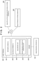
- the user terminal 200 is operated by a user and includes the browser (a web browser) 201, the Scan Server 202, and a driver 205.
- the user can use web applications (the web application service providing system 300 and the web storage system 400) via the browser 201 in the user terminal 200.
- the Scan Server 202 includes a web server unit 203 and an image reading apparatus operation unit 204.
- the browser 201 communicates with the web applications (the web application service providing system 300 and the web storage system 400).
- the Scan Server 202 is a program (a web server program) operating in the user terminal 200 in which the browser 201 communicating with the web applications (the web application service providing system 300 and the web storage system 400) operates.
- the web server unit 203 of the Scan Server 202 may listen with the host name "localhost" in the user terminal 200 in order to not to operate as a web server capable of name resolution from browsers in any user terminals by avoiding communication blocking by a firewall (not shown).
- the Scan Server 202 provides an endpoint (the image reading apparatus operation unit 204) for performing image reading processing using the image reading apparatus 100 connected to the user terminal 200, and an endpoint (the web server unit 203) for communicating with a web system in a domain different from the domain of a web system that sends a request.
- the image reading apparatus operation unit 204 can be instructed to operate the image reading apparatus 100.
- the image reading apparatus operation unit 204 operates the image reading apparatus 100 connected to the user terminal 200.
- the driver 205 is software for controlling the image reading apparatus 100.
- the Scan Server 202 belongs to the domain C and the web application service providing system 300 belongs to the domain A, so that they belong to different domains. Consequently, if the web application of the web application service providing system 300, operating on the browser 201 in the user terminal 200, is going to communicate with the web server unit 203 of the Scan Server 202, it will be a cross-domain request.
- the web application of the web application service providing system 300 operating on the browser 201 communicates with the Scan Server 202, it attempts a request transmission according to the CORS standard specifications (HTTP message transmission) in order to address the cross-domain request.
- the HTTP messages also include requests/responses based on HTTPS communications.
- processing of permitting the cross-domain request and enabling cross-domain communications will be specifically described with reference to FIGS. 5 and 6 .
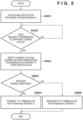
- FIG 5 is a flowchart illustrating processing in the browser 201.
- the user operating the user terminal 200 is a user of the web application service providing system 300
- the user accesses the web application service providing system 300 via the browser 201 in the user terminal 200.
- the browser 201 accesses the domain of the web application service providing system 300 (domain A) (S5001).
- the browser 201 determines whether or not a request transmission (HTTP message transmission) to a different domain (e.g., the domain of the Scan Server 202 (domain C)) occurs (S5002). If a request transmission to a different domain does not occur (NO in S5002), the process is repeated.
- a request transmission HTTP message transmission
- domain C domain of the Scan Server 202
- the browser 201 in the user terminal 200 performs a request transmission according to the CORS specifications (HTTP message transmission) to the Scan Server 202 by specifying the domain of the web application service providing system 300 (domain A) in the Origin header in the request (S5003).
- HTTP HyperText Transfer Protocol
- the request to the Scan Server 202 may be based on WebSocket or other protocols.
- the browser 201 determines whether or not a normal response is received from the Scan Server 202 (S5004).
- a normal response is received if the domain of the web application service providing system 300 (domain A) is permitted in the Scan Server 202; otherwise, an error response is received.
- the browser 201 (the web application of the web application service providing system 300 operating on the browser 201) can communicate with the Scan Server 202 (S5005). That is, cross-domain communications (communications between the domain A and the domain C) are enabled. If an error response is received from the Scan Server 202 (NO in S5004), the browser 201 (the web application of the web application service providing system 300 operating on the browser 201) cannot communicate with the Scan Server 202.
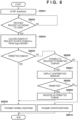
- FIG 6 is a flowchart illustrating processing in the Scan Server 202.
- the Scan Server 202 determines whether or not a request (an HTTP message) according to CORS is received (S6002). If it is not received (NO in S6002), the process is repeated.
- the domain (domain A) of the request source (the browser 201) is acquired from the Origin header in the request (S6003). It is determined whether or not the acquired domain is registered as a permitted domain (whether or not it is set to be permitted) (S6004). If the domain is registered (YES in S6004), a normal response is transmitted to the domain (domain A) of the request source (the browser 201) (S6005).
- the Scan Server 202 determines whether or not the domain included in the Origin header can be registered as a permitted domain (S6006). Whether or not the domain can be registered may be determined in the following ways. For example, the maximum number of permitted domains is preset, and if the maximum number is currently not reached, the domain can be registered; if the maximum number is reached, the domain cannot be registered. In another way, impermissible domains are preset (e.g., a black list), and if the domain included in the Origin header is an impermissible domain, the domain cannot be registered; otherwise, the domain can be registered. In still another way, permissible domains are preset (e.g., a white list), and if the domain included in the Origin header is a permissible domain, the domain can be registered; otherwise, the domain cannot be registered.
- the maximum number of permitted domains is preset, and if the maximum number is currently not reached, the domain can be registered; if the maximum number is reached, the domain cannot be registered.
- Determining whether or not the domain can be registered in S6006 can eliminate display of unnecessary confirmation messages to the user. If the domain cannot be registered (NO in S6006), an error response is transmitted to the domain (domain A) of the request source (the browser 201) as an operation of prohibiting the CORS-based access (S6010).
- S6006 If the domain can be registered (YES in S6006), a confirmation message for CORS-setting permission is displayed on the user terminal 200 (S6007).
- the Scan Server 202 determines whether or not the request from the web application service providing system 300 is permitted by the user (S6008). If the request is not permitted (NO in S6008), the process proceeds to S6010.
- the domain (domain A) is set as a permitted domain and registered (S6009). The process then proceeds to S6005.
- the processing from S6006 to S6009 may be omitted, and if the domain is not registered as a permitted domain (NO in S6004), an error response may be transmitted (S6010). Also, the processing in S6004 and S6006 may be omitted for the received request, and the confirmation message for CORS-setting permission may be displayed on the user terminal 200 (S6007). Also, the processing of determining whether or not the acquired domain is a permitted domain (S6004) may be omitted, and a normal response may be transmitted (S6005).
- the Scan Server 202 requires an access token of the web storage system 400 when transmitting information including the result of image reading processing (read image data) to the web storage system 400 (domain B). Therefore, before starting the image reading processing, the web application of the web application service providing system 300 operating on the browser 201 in the user terminal 200 acquires the access token of the web storage system 400 via the Scan Server 202 and stores the access token.
- authentication information e.g., an access token
- OAuth 2.0 an authentication protocol in conventional art
- FIG 7 is a sequence diagram illustrating an exemplary functional configuration of the system according to an embodiment.
- a user 1000 instructs, via the browser 201, an operation to start authentication (S10010).
- the browser 201 transmits a request for an authentication screen to the web storage service 400 (S10011).
- the web storage service 400 transmits a response with the authentication screen to the browser 201 (S10012).
- the user 1000 instructs an authentication operation via the browser 201 (S10020).
- the browser 201 transmits authentication information and a request for an authorization screen to the web storage service 400 (S10021).
- the web storage service 400 transmits a response with the authorization screen to the browser 201 (S10022).
- the user 1000 instructs an authorization operation via the browser 201 (S10030).
- the browser 201 transmits authorization information and a request for an authorization code to the web storage service 400 (S10031).
- the web storage service 400 transmits the authorization code and redirection to the browser 201 (S10032).
- the browser 201 transmits a request for an access token to the Scan Server 202 (S10033).
- the Scan Server 202 transmits a request for the access token to the web storage service 400 (S10034).
- the web storage service 400 transmits a response with the access token to the Scan Server 202 (S10035).
- the Scan Server 202 transmits a response with the access token to the browser 201 (S10036).
- the browser 201 stores the received access token.
- the access token may also be stored at the Scan Server 202.
- the user instructs, via the browser 201, image reading processing (S10050).
- the instruction includes information about scan settings (e.g., the storage destination, resolution, monochrome/color selection, reading size, and file format).
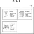
- FIG 8 is a diagram illustrating an exemplary screen displayed on the browser 201.
- a DOCUMENT button is selected to instruct image reading with specified scan settings (monochrome, 300 dpi, A4 size, double-sided).
- the web application of the web application service providing system 300 operating on the browser 201 is not limited to the illustration in FIG 8 but may be freely customized by the user.
- the web application of the web application service providing system 300 operating on the browser 201 in the user terminal 200 transmits the access token acquired in S10035, the scan setting information, and a request to start image reading processing (a request about image reading) to the Scan Server 202 (S10051).
- the Scan Server 202 holds the access token acquired in S10035.
- the Scan Server 202 may have a lock function by which a unique connection ID (identification information) is issued to the request source to limit the user of the apparatus.
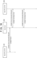
- FIG 9 is a diagram illustrating an example in which a web application 301 of the web application service providing system 300 operating on the browser 201 in the user terminal 200 performs image reading processing using the lock function.
- the web application 301 requests the Scan Server 202 to issue a new connection ID. Once the Scan Server 202 issues a new connection ID, the Scan Server 202 rejects use of the Scan Server 202 by another application 302 having no connection ID.
- the image reading processing with the connection ID is started, and when the use of the image reading apparatus 100 is finished, the web application 301 transmits a disconnection request with the connection ID.
- the Scan Server 202 discards the existing connection ID and returns to the state in which it waits for a request to issue a new connection ID.
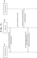
- FIG 11 is a diagram illustrating a process where an issued connection ID can be discarded after a certain time period. After the certain time period, an operation with the existing connection ID is rejected if a new connection ID has been issued in response to a new connection request. Here, upon reception of this new connection request, the new connection ID may be issued after the existing connection ID is discarded. However, as in FIG 12 , if a new connection request is not received even after the lapse of the certain time period and an operation request with the existing connection ID is received, the request may be accepted.
- the certain time period before unlocking may be specified via the web application.
- the Scan Server 202 transmits the scan setting information and a request to start image reading processing to the driver 205, and the driver 205 transmits the scan setting information and the request to start image reading processing to the image reading apparatus 100 (S10052).
- the image reading apparatus 100 starts driving the first to third transport units 10 to 30, as described in FIG 1 .
- the carrier media S stacked on the placement table 1 are transported one by one, starting with the carrier medium S at the bottom in the stack.
- the control unit 8 causes the image reading units 70 to start reading images on each carrier medium S transported by the second transport unit 20, according to the received scan setting information.
- the control unit 8 saves the read images in the image memory 89, performs optical text recognition processing on the saved image data, recognizes the form type, and attaches information about the form type to the image data.
- the control unit 8 then successively transmits the acquired image data to the driver 205.
- the driver 205 transmits the acquired image data to the Scan Server 202 (S10053).
- the carrier medium S having its images read is ejected by the third transport unit 30 onto the ejection tray 2, and the image reading processing on that carrier medium S is completed.
- the image reading apparatus 100 may fail to read the carrier media S. Possible causes include that the image reading apparatus 100 is clogged with the carrier media S, and that the cover of the image reading apparatus 100 is opened to interrupt the reading. As in FIG 13 , if the image data reading fails, the image reading apparatus 100 notifies the driver 205 of the reading failure and its cause instead of transmitting image data. The driver 205 then notifies the Scan Server 202 of the image reading failure and its cause. The Scan Server 202 thus fails to perform the image reading processing and terminates without acquiring image data. Thereafter, as long as the image reading apparatus 100 is connected to the user terminal 200, the Scan Server 202 may periodically inquire of the driver 205 about the state of the image reading apparatus 100 to keep track of the possibility of starting the next image reading processing. The processing of inquiry about the state of the image reading apparatus 100 may be terminated after a certain time period or after a certain number of times of inquiry.
- the Scan Server 202 transmits the access token held in the Scan Server 202 and specified by the web application of the web application service providing system 300 operating on the browser 201 in the user terminal 200, and a request to accept transmission of information including the result of the image reading processing (image data), to the web storage service 6006 in which the image data is to be stored (S 10054).
- the information including the result of the image reading processing includes, for example, information associating the image data with the user, OCR information about the image data, and timestamps.
- the web storage service 6006 transmits a response to the Scan Server 202 (S10055).
- the web application of the web application service providing system 300 operating on the browser 201 in the user terminal 200 then transmits, to the Scan Server 202, a request for the information including the result of the image reading processing and for the transmission result, as appropriate (S 10056).
- the Scan Server 202 transmits a response to the browser 201 (S 10057).
- the web application of the web application service providing system 300 (domain A) operating on the browser 201 in the user terminal 200 can perform, only through the communications with the Scan Server 202, the image reading processing and the transmission of the information including the result of the image reading processing (the read image data) to the web storage system 400 (domain B).
- the processing of acquiring the access token (S 10010 to S10036) in FIG 7 may be omitted.
- the web application of the web application service providing system 300 operating on the browser 201 provides, to the Scan Server 202, authentication information (e.g., an access token) acquired from the web storage system 400 residing in a different domain.
- the Scan Server 202 can thus transmit information including the result of the image reading processing to the web storage system 400.
- the request transmission from the Scan Server 202 to the web storage system 400 is not regarded as cross-domain access, because it is a communication not from the browser 201 but from a general application. Therefore, via the Scan Server 202 in the user terminal 200, the web application of the web application service providing system 300 operating on the browser 201 can transmit the information including the result of the image reading processing (the image data) acquired from the image reading apparatus 100 to the web storage system 400, without direct communications with the web storage system 400 residing in a domain different from the domain of the web application service providing system 300.
- domain A and the domain B have been assumed to be different, they may be the same. For example, this is the case where the web application and a URL for receiving the information including the result of the image reading processing are provided in the same domain.
- the present invention may be realized by supplying a program for implementing one or more functions of the above embodiments to a system or apparatus via a network or storage medium, where one or more processors in a computer of the system or apparatus reads and executes the program.
- the present invention may also be realized by a circuit (e.g., ASIC) implementing the one or more functions.
Landscapes
- Engineering & Computer Science (AREA)
- Theoretical Computer Science (AREA)
- General Engineering & Computer Science (AREA)
- Physics & Mathematics (AREA)
- General Physics & Mathematics (AREA)
- Human Computer Interaction (AREA)
- Computer Security & Cryptography (AREA)
- Computer Hardware Design (AREA)
- Software Systems (AREA)
- Signal Processing (AREA)
- Multimedia (AREA)
- Health & Medical Sciences (AREA)
- General Health & Medical Sciences (AREA)
- Bioethics (AREA)
- Automation & Control Theory (AREA)
- Computer Networks & Wireless Communication (AREA)
- Facsimiles In General (AREA)
- Information Transfer Between Computers (AREA)
Claims (4)
- Informationsverarbeitungsvorrichtung (200) miteinem Webbrowser (201),einem Webserverprogramm (202), das zu einer ersten Domain gehört, undeinem Treiber (205), der mit einer Bildleseeinrichtung (100) kommuniziert, die mit der Informationsverarbeitungsvorrichtung verbunden ist,wobei das Webserverprogramm (202), wenn es durch die Informationsverarbeitungsvorrichtung ausgeführt wird, die Informationsverarbeitungsvorrichtung veranlasst, dass sie arbeitet als:erste Empfangseinrichtung zum Empfangen einer HTTP-Nachricht von einer Webapplikation, die zu einer zweiten Domain gehört, die von der ersten Domain verschieden ist, und die durch den Webbrowser ausgeführt wird,erste Sendeeinrichtung zum Senden von Abtasteinstellinformationen und einer Anfrage zum Starten eines Bildleseprozesses von der ersten Empfangseinrichtung, die die HTTP-Nachricht empfangen hat, zu dem Treiber,zweite Empfangseinrichtung zum Empfangen von Bildinformationen von dem Treiber, die durch die Bildleseeinrichtung ausgegeben werden, undzweite Sendeeinrichtung zum Senden (S10054) einer Anfrage zum Akzeptieren einer Übertragung der Bildinformationen, die durch die zweite Empfangseinrichtung empfangen werden, und von Informationen, die für eine Authentifizierung verwendet werden, zu einem Webspeicherdienst (400), in dem die Bildinformationen zu speichern sind,wobei das Webserverprogramm (202) die für die Authentifizierung verwendeten Informationen über den Webbrowser von der Webapplikation beschafft (S10051).
- Steuerverfahren in einer Informationsverarbeitungsvorrichtung (200), wobeidie Informationsverarbeitungsvorrichtung umfassteinen Webbrowser (201),ein Webserverprogramm (202), das zu einer ersten Domain gehört, undeinen Treiber (205), der mit einer Bildleseeinrichtung (100) kommuniziert, die mit der Informationsverarbeitungsvorrichtung verbunden ist, unddas Webserverprogramm (202), wenn es durch die Informationsverarbeitungsvorrichtung ausgeführt wird, durchführt:Empfangen einer HTTP-Nachricht von einer Webapplikation, die zu einer zweiten Domain gehört, die von der ersten Domain verschieden ist, und die auf dem Webbrowser ausgeführt wird,Senden von Abtasteinstellinformationen und einer Anfrage zum Starten eines Bildleseprozesses zu dem Treiber nach Empfangen der HTTP-Nachricht,Empfangen von Bildinformationen von dem Treiber, die durch die Bildleseeinrichtung ausgegeben werden, undSenden (S10054) einer Anfrage zum Akzeptieren einer Übertragung der durch die Bildleseeinrichtung ausgegebenen Bildinformationen und von Informationen, die für eine Authentifizierung verwendet werden, zu einem Webspeicherdienst (400), in dem die Bildinformationen zu speichern sind,wobei das Webserverprogramm die für die Authentifizierung verwendeten Informationen über den Webbrowser von der Webapplikation beschafft (S10051).
- Programm, das, wenn es durch einen Computer ausgeführt wird, den Computer zum Arbeiten als jede der Einrichtungen veranlasst, die in der Informationsverarbeitungsvorrichtung nach Anspruch 1 enthalten sind.
- Informationsverarbeitungssystem miteiner Informationsverarbeitungsvorrichtung (200), die einen Webbrowser (201) und ein Webserverprogramm (202) enthält, das zu einer ersten Domain gehört, undeiner Bildleseeinrichtung (100), die mit der Informationsverarbeitungsvorrichtung verbunden ist, wobeidie Informationsverarbeitungsvorrichtung einen Treiber (205) umfasst, der mit der Bildleseeinrichtung kommuniziert, undder Webserver, wenn er durch die Informationsverarbeitungsvorrichtung ausgeführt wird, die Informationsverarbeitungsvorrichtung veranlasst, dass sie arbeitet als:erste Empfangseinrichtung zum Empfangen einer HTTP-Nachricht von einer Webapplikation, die zu einer zweiten Domain gehört, die von der ersten Domain verschieden ist, und die auf dem Webbrowser ausgeführt wird,erste Sendeeinrichtung zum Senden von Abtasteinstellinformationen und einer Anfrage zum Starten eines Bildleseprozesses von der ersten Empfangseinrichtung, die die HTTP-Nachricht empfangen hat, zu dem Treiber,zweite Empfangseinrichtung zum Empfangen von Bildinformationen, die durch die Bildleseeinrichtung ausgegeben werden, von dem Treiber, undzweite Sendeeinrichtung zum Senden (S10054) einer Anfrage zum Akzeptieren einer Übertragung der durch die zweite Empfangseinrichtung empfangenen Bildinformationen und von Informationen, die für eine Authentifizierung verwendet werden, zu einem Webspeicherdienst (400), in dem die Bildinformationen zu speichern sind,wobei das Webserverprogramm die für die Authentifizierung verwendeten Informationen über den Webbrowser von der Webapplikation beschafft.
Applications Claiming Priority (3)
| Application Number | Priority Date | Filing Date | Title |
|---|---|---|---|
| JP2016233612 | 2016-11-30 | ||
| PCT/JP2017/040722 WO2018101011A1 (ja) | 2016-11-30 | 2017-11-13 | 情報処理装置およびその制御方法、プログラムおよび情報処理システム |
| EP17876254.8A EP3550460B1 (de) | 2016-11-30 | 2017-11-13 | Informationsverarbeitungsvorrichtung, steuerungsverfahren dafür, programm und informationsverarbeitungssystem |
Related Parent Applications (2)
| Application Number | Title | Priority Date | Filing Date |
|---|---|---|---|
| EP17876254.8A Division EP3550460B1 (de) | 2016-11-30 | 2017-11-13 | Informationsverarbeitungsvorrichtung, steuerungsverfahren dafür, programm und informationsverarbeitungssystem |
| EP17876254.8A Division-Into EP3550460B1 (de) | 2016-11-30 | 2017-11-13 | Informationsverarbeitungsvorrichtung, steuerungsverfahren dafür, programm und informationsverarbeitungssystem |
Publications (2)
| Publication Number | Publication Date |
|---|---|
| EP3779744A1 EP3779744A1 (de) | 2021-02-17 |
| EP3779744B1 true EP3779744B1 (de) | 2024-04-03 |
Family
ID=62241374
Family Applications (2)
| Application Number | Title | Priority Date | Filing Date |
|---|---|---|---|
| EP20200215.0A Active EP3779744B1 (de) | 2016-11-30 | 2017-11-13 | Informationsverarbeitungseinrichtung, steuerungsverfahren dafür, programm und informationsverarbeitungssystem |
| EP17876254.8A Active EP3550460B1 (de) | 2016-11-30 | 2017-11-13 | Informationsverarbeitungsvorrichtung, steuerungsverfahren dafür, programm und informationsverarbeitungssystem |
Family Applications After (1)
| Application Number | Title | Priority Date | Filing Date |
|---|---|---|---|
| EP17876254.8A Active EP3550460B1 (de) | 2016-11-30 | 2017-11-13 | Informationsverarbeitungsvorrichtung, steuerungsverfahren dafür, programm und informationsverarbeitungssystem |
Country Status (5)
| Country | Link |
|---|---|
| US (2) | US10635364B2 (de) |
| EP (2) | EP3779744B1 (de) |
| JP (2) | JP6596597B2 (de) |
| ES (2) | ES2895426T3 (de) |
| WO (1) | WO2018101011A1 (de) |
Families Citing this family (5)
| Publication number | Priority date | Publication date | Assignee | Title |
|---|---|---|---|---|
| WO2018101011A1 (ja) | 2016-11-30 | 2018-06-07 | キヤノン電子株式会社 | 情報処理装置およびその制御方法、プログラムおよび情報処理システム |
| US10846029B2 (en) * | 2017-06-13 | 2020-11-24 | Bixolon Co., Ltd. | Printing apparatus to acquire print data and transmit a request to an external apparatus to close websocket communication when predetermined time period elapses |
| US11681605B2 (en) * | 2020-09-13 | 2023-06-20 | Oracle International Corporation | Out-of-the-box telemetry for rich-client application runtime frameworks |
| CN112477462B (zh) * | 2020-11-10 | 2022-04-15 | 中山火炬职业技术学院 | 非在线铝质气雾罐数码打样方法 |
| JP7817839B2 (ja) | 2022-01-12 | 2026-02-19 | キヤノン株式会社 | 電子機器、制御方法、及びプログラム |
Family Cites Families (20)
| Publication number | Priority date | Publication date | Assignee | Title |
|---|---|---|---|---|
| JP3485252B2 (ja) * | 1999-06-16 | 2004-01-13 | インターナショナル・ビジネス・マシーンズ・コーポレーション | 情報処理方法、情報端末支援サーバ、コラボレーション・システム、情報処理プログラムを格納する記憶媒体 |
| JP4703333B2 (ja) * | 2005-09-26 | 2011-06-15 | エヌ・ティ・ティ・ソフトウェア株式会社 | 電子メール処理プログラム |
| EP2144421A1 (de) * | 2008-07-08 | 2010-01-13 | Gemplus | Verfahren zur Verwaltung des Zugriffs einer Fernvorrichtung auf von einer lokalen Vorrichtung erreichbare Daten und zugehöriges System |
| JP2012015979A (ja) * | 2010-07-05 | 2012-01-19 | Canon Inc | 情報処理システム、情報処理装置、それらの制御方法、及びプログラム |
| JP2012147335A (ja) * | 2011-01-13 | 2012-08-02 | Canon Inc | スキャンシステム、プリントシステム、サービス提供システム、および制御方法 |
| JP2012185650A (ja) | 2011-03-04 | 2012-09-27 | Canon Inc | 情報処理装置、情報処理システム、情報処理装置の制御方法、及びプログラム |
| JP5505391B2 (ja) * | 2011-09-30 | 2014-05-28 | トヨタ自動車株式会社 | 環境予測装置 |
| KR20130071138A (ko) * | 2011-12-20 | 2013-06-28 | 삼성전자주식회사 | 사용자 정보를 이용하는 화상 형성 작업의 수행 방법 및 이를 수행하기 위한 화상 형성 장치 |
| US8898766B2 (en) * | 2012-04-10 | 2014-11-25 | Spotify Ab | Systems and methods for controlling a local application through a web page |
| US8994967B1 (en) | 2012-06-29 | 2015-03-31 | Emc Corporation | Scanner web service for web application and scanner driver communication |
| JP6065542B2 (ja) | 2012-11-26 | 2017-01-25 | ブラザー工業株式会社 | 画像処理装置および通信プログラム |
| US9088573B2 (en) | 2013-03-22 | 2015-07-21 | Dropbox, Inc. | Local server for synced online content management system |
| JP6109617B2 (ja) | 2013-03-26 | 2017-04-05 | 株式会社東芝 | 情報出力装置、情報操作装置、およびプログラム |
| JP6195357B2 (ja) * | 2013-07-08 | 2017-09-13 | キヤノン株式会社 | 画像処理装置、その制御方法、及びプログラム |
| US20150143467A1 (en) * | 2013-11-19 | 2015-05-21 | Intel-Ge Care Innovations Llc | System and method for facilitating communication between a web application and a local peripheral device through a native service |
| JP6346443B2 (ja) | 2014-01-08 | 2018-06-20 | キヤノン株式会社 | 情報処理装置およびその制御方法、並びにプログラム |
| CN105471824A (zh) * | 2014-09-03 | 2016-04-06 | 阿里巴巴集团控股有限公司 | 实现浏览器调用本地业务组件的方法、装置及系统 |
| JP6119709B2 (ja) * | 2014-09-29 | 2017-04-26 | ブラザー工業株式会社 | サービスプロバイダ装置、プログラム及びサービス提供方法 |
| JP6510258B2 (ja) * | 2015-02-10 | 2019-05-08 | 日本電信電話株式会社 | ユーザ属性情報管理システムおよびユーザ属性情報管理方法 |
| WO2018101011A1 (ja) | 2016-11-30 | 2018-06-07 | キヤノン電子株式会社 | 情報処理装置およびその制御方法、プログラムおよび情報処理システム |
-
2017
- 2017-11-13 WO PCT/JP2017/040722 patent/WO2018101011A1/ja not_active Ceased
- 2017-11-13 ES ES17876254T patent/ES2895426T3/es active Active
- 2017-11-13 ES ES20200215T patent/ES2980433T3/es active Active
- 2017-11-13 EP EP20200215.0A patent/EP3779744B1/de active Active
- 2017-11-13 JP JP2018549277A patent/JP6596597B2/ja active Active
- 2017-11-13 EP EP17876254.8A patent/EP3550460B1/de active Active
-
2018
- 2018-12-19 JP JP2018237605A patent/JP6596564B2/ja active Active
-
2019
- 2019-05-24 US US16/422,729 patent/US10635364B2/en active Active
-
2020
- 2020-01-02 US US16/733,118 patent/US10809950B2/en active Active
Also Published As
| Publication number | Publication date |
|---|---|
| US10635364B2 (en) | 2020-04-28 |
| EP3550460A4 (de) | 2020-08-12 |
| WO2018101011A1 (ja) | 2018-06-07 |
| JP2019075144A (ja) | 2019-05-16 |
| ES2895426T3 (es) | 2022-02-21 |
| JPWO2018101011A1 (ja) | 2019-01-17 |
| US20200192614A1 (en) | 2020-06-18 |
| JP6596597B2 (ja) | 2019-10-30 |
| EP3779744A1 (de) | 2021-02-17 |
| ES2980433T3 (es) | 2024-10-01 |
| EP3550460B1 (de) | 2021-09-29 |
| EP3550460A1 (de) | 2019-10-09 |
| US20190278538A1 (en) | 2019-09-12 |
| US10809950B2 (en) | 2020-10-20 |
| JP6596564B2 (ja) | 2019-10-23 |
Similar Documents
| Publication | Publication Date | Title |
|---|---|---|
| US10809950B2 (en) | Information processing apparatus, control method therefor, non-transitory computer-readable medium, and information processing system | |
| EP1289252B1 (de) | Netzwerkbasierte Bildeingabeabtastung, die von einem Abtaster eingeführt wird | |
| EP1457890A2 (de) | Methode und Apparat zur Übermittlung einer Dokument Service Anfrage von einem mobilen Gerät | |
| US20170013147A1 (en) | Information processing apparatus, image processing apparatus, medium, and user interface | |
| US20040035934A1 (en) | Data recording medium, reading device, recording device, and methods thereof | |
| US10152289B2 (en) | Communication apparatus that obtains application information from a communication partner apparatus existing within an effective communication range, control method therefor, and storage medium | |
| US20120120440A1 (en) | Scanner management apparatus, scanning system, and scanner management method | |
| CN110875991A (zh) | 图像形成装置 | |
| US11076059B2 (en) | Data transmission apparatus that can set destination such as e-mail address received from external apparatus on transmission setting screen and control method therefor | |
| US11412103B2 (en) | Image processing apparatus for displaying an analysis result of a multi-cropping scan processing | |
| KR20200064910A (ko) | 데이터 처리 시스템, 데이터 처리 시스템에 대한 제어 방법 및 기억 매체 | |
| US9699338B2 (en) | Image forming apparatus | |
| JP2021150933A (ja) | 情報処理システム | |
| JP2017224114A (ja) | 装置、制御方法およびプログラム | |
| US20220413774A1 (en) | Print system and print method | |
| US9383952B1 (en) | Systems and methods for overriding a print ticket when printing from a mobile device | |
| JP2019204154A (ja) | 情報処理装置、情報処理の制御方法、プログラムおよび情報処理システム | |
| WO2025135033A1 (ja) | 画像読取装置、画像読取システム、画像読取装置の制御方法、及びプログラム | |
| US10965824B2 (en) | Methods and systems for print jobs transfer via an external storage device | |
| US20200236229A1 (en) | Image processing apparatus and method | |
| CN1979513A (zh) | 打印系统及其控制方法、图像形成设备和打印系统控制器 | |
| US20120005336A1 (en) | Information processing system, information processing apparatus, control methods therefor, and computer programs | |
| US20230114500A1 (en) | Image reading apparatus to set information processing apparatus capable of executing imaging control | |
| US20250021277A1 (en) | Information processing system and non-transitory computer readable program | |
| US20230247147A1 (en) | Image processing apparatus, image processing system, and storage medium |
Legal Events
| Date | Code | Title | Description |
|---|---|---|---|
| PUAI | Public reference made under article 153(3) epc to a published international application that has entered the european phase |
Free format text: ORIGINAL CODE: 0009012 |
|
| STAA | Information on the status of an ep patent application or granted ep patent |
Free format text: STATUS: REQUEST FOR EXAMINATION WAS MADE |
|
| 17P | Request for examination filed |
Effective date: 20201006 |
|
| AC | Divisional application: reference to earlier application |
Ref document number: 3550460 Country of ref document: EP Kind code of ref document: P |
|
| AK | Designated contracting states |
Kind code of ref document: A1 Designated state(s): AL AT BE BG CH CY CZ DE DK EE ES FI FR GB GR HR HU IE IS IT LI LT LU LV MC MK MT NL NO PL PT RO RS SE SI SK SM TR |
|
| GRAP | Despatch of communication of intention to grant a patent |
Free format text: ORIGINAL CODE: EPIDOSNIGR1 |
|
| STAA | Information on the status of an ep patent application or granted ep patent |
Free format text: STATUS: GRANT OF PATENT IS INTENDED |
|
| INTG | Intention to grant announced |
Effective date: 20231019 |
|
| GRAS | Grant fee paid |
Free format text: ORIGINAL CODE: EPIDOSNIGR3 |
|
| P01 | Opt-out of the competence of the unified patent court (upc) registered |
Effective date: 20240124 |
|
| GRAA | (expected) grant |
Free format text: ORIGINAL CODE: 0009210 |
|
| STAA | Information on the status of an ep patent application or granted ep patent |
Free format text: STATUS: THE PATENT HAS BEEN GRANTED |
|
| AC | Divisional application: reference to earlier application |
Ref document number: 3550460 Country of ref document: EP Kind code of ref document: P |
|
| AK | Designated contracting states |
Kind code of ref document: B1 Designated state(s): AL AT BE BG CH CY CZ DE DK EE ES FI FR GB GR HR HU IE IS IT LI LT LU LV MC MK MT NL NO PL PT RO RS SE SI SK SM TR |
|
| REG | Reference to a national code |
Ref country code: CH Ref legal event code: EP |
|
| REG | Reference to a national code |
Ref country code: DE Ref legal event code: R096 Ref document number: 602017080749 Country of ref document: DE |
|
| REG | Reference to a national code |
Ref country code: IE Ref legal event code: FG4D |
|
| REG | Reference to a national code |
Ref country code: LT Ref legal event code: MG9D |
|
| REG | Reference to a national code |
Ref country code: NL Ref legal event code: MP Effective date: 20240403 |
|
| REG | Reference to a national code |
Ref country code: AT Ref legal event code: MK05 Ref document number: 1673141 Country of ref document: AT Kind code of ref document: T Effective date: 20240403 |
|
| PG25 | Lapsed in a contracting state [announced via postgrant information from national office to epo] |
Ref country code: NL Free format text: LAPSE BECAUSE OF FAILURE TO SUBMIT A TRANSLATION OF THE DESCRIPTION OR TO PAY THE FEE WITHIN THE PRESCRIBED TIME-LIMIT Effective date: 20240403 |
|
| PG25 | Lapsed in a contracting state [announced via postgrant information from national office to epo] |
Ref country code: NL Free format text: LAPSE BECAUSE OF FAILURE TO SUBMIT A TRANSLATION OF THE DESCRIPTION OR TO PAY THE FEE WITHIN THE PRESCRIBED TIME-LIMIT Effective date: 20240403 |
|
| REG | Reference to a national code |
Ref country code: ES Ref legal event code: FG2A Ref document number: 2980433 Country of ref document: ES Kind code of ref document: T3 Effective date: 20241001 |
|
| PG25 | Lapsed in a contracting state [announced via postgrant information from national office to epo] |
Ref country code: IS Free format text: LAPSE BECAUSE OF FAILURE TO SUBMIT A TRANSLATION OF THE DESCRIPTION OR TO PAY THE FEE WITHIN THE PRESCRIBED TIME-LIMIT Effective date: 20240803 |
|
| PG25 | Lapsed in a contracting state [announced via postgrant information from national office to epo] |
Ref country code: BG Free format text: LAPSE BECAUSE OF FAILURE TO SUBMIT A TRANSLATION OF THE DESCRIPTION OR TO PAY THE FEE WITHIN THE PRESCRIBED TIME-LIMIT Effective date: 20240403 |
|
| PG25 | Lapsed in a contracting state [announced via postgrant information from national office to epo] |
Ref country code: FI Free format text: LAPSE BECAUSE OF FAILURE TO SUBMIT A TRANSLATION OF THE DESCRIPTION OR TO PAY THE FEE WITHIN THE PRESCRIBED TIME-LIMIT Effective date: 20240403 Ref country code: HR Free format text: LAPSE BECAUSE OF FAILURE TO SUBMIT A TRANSLATION OF THE DESCRIPTION OR TO PAY THE FEE WITHIN THE PRESCRIBED TIME-LIMIT Effective date: 20240403 |
|
| PG25 | Lapsed in a contracting state [announced via postgrant information from national office to epo] |
Ref country code: GR Free format text: LAPSE BECAUSE OF FAILURE TO SUBMIT A TRANSLATION OF THE DESCRIPTION OR TO PAY THE FEE WITHIN THE PRESCRIBED TIME-LIMIT Effective date: 20240704 |
|
| PG25 | Lapsed in a contracting state [announced via postgrant information from national office to epo] |
Ref country code: PT Free format text: LAPSE BECAUSE OF FAILURE TO SUBMIT A TRANSLATION OF THE DESCRIPTION OR TO PAY THE FEE WITHIN THE PRESCRIBED TIME-LIMIT Effective date: 20240805 |
|
| PG25 | Lapsed in a contracting state [announced via postgrant information from national office to epo] |
Ref country code: CZ Free format text: LAPSE BECAUSE OF FAILURE TO SUBMIT A TRANSLATION OF THE DESCRIPTION OR TO PAY THE FEE WITHIN THE PRESCRIBED TIME-LIMIT Effective date: 20240403 |
|
| PG25 | Lapsed in a contracting state [announced via postgrant information from national office to epo] |
Ref country code: AT Free format text: LAPSE BECAUSE OF FAILURE TO SUBMIT A TRANSLATION OF THE DESCRIPTION OR TO PAY THE FEE WITHIN THE PRESCRIBED TIME-LIMIT Effective date: 20240403 |
|
| PG25 | Lapsed in a contracting state [announced via postgrant information from national office to epo] |
Ref country code: PL Free format text: LAPSE BECAUSE OF FAILURE TO SUBMIT A TRANSLATION OF THE DESCRIPTION OR TO PAY THE FEE WITHIN THE PRESCRIBED TIME-LIMIT Effective date: 20240403 |
|
| PG25 | Lapsed in a contracting state [announced via postgrant information from national office to epo] |
Ref country code: LV Free format text: LAPSE BECAUSE OF FAILURE TO SUBMIT A TRANSLATION OF THE DESCRIPTION OR TO PAY THE FEE WITHIN THE PRESCRIBED TIME-LIMIT Effective date: 20240403 |
|
| PG25 | Lapsed in a contracting state [announced via postgrant information from national office to epo] |
Ref country code: PT Free format text: LAPSE BECAUSE OF FAILURE TO SUBMIT A TRANSLATION OF THE DESCRIPTION OR TO PAY THE FEE WITHIN THE PRESCRIBED TIME-LIMIT Effective date: 20240805 Ref country code: PL Free format text: LAPSE BECAUSE OF FAILURE TO SUBMIT A TRANSLATION OF THE DESCRIPTION OR TO PAY THE FEE WITHIN THE PRESCRIBED TIME-LIMIT Effective date: 20240403 Ref country code: NO Free format text: LAPSE BECAUSE OF FAILURE TO SUBMIT A TRANSLATION OF THE DESCRIPTION OR TO PAY THE FEE WITHIN THE PRESCRIBED TIME-LIMIT Effective date: 20240703 Ref country code: LV Free format text: LAPSE BECAUSE OF FAILURE TO SUBMIT A TRANSLATION OF THE DESCRIPTION OR TO PAY THE FEE WITHIN THE PRESCRIBED TIME-LIMIT Effective date: 20240403 Ref country code: IS Free format text: LAPSE BECAUSE OF FAILURE TO SUBMIT A TRANSLATION OF THE DESCRIPTION OR TO PAY THE FEE WITHIN THE PRESCRIBED TIME-LIMIT Effective date: 20240803 Ref country code: HR Free format text: LAPSE BECAUSE OF FAILURE TO SUBMIT A TRANSLATION OF THE DESCRIPTION OR TO PAY THE FEE WITHIN THE PRESCRIBED TIME-LIMIT Effective date: 20240403 Ref country code: GR Free format text: LAPSE BECAUSE OF FAILURE TO SUBMIT A TRANSLATION OF THE DESCRIPTION OR TO PAY THE FEE WITHIN THE PRESCRIBED TIME-LIMIT Effective date: 20240704 Ref country code: FI Free format text: LAPSE BECAUSE OF FAILURE TO SUBMIT A TRANSLATION OF THE DESCRIPTION OR TO PAY THE FEE WITHIN THE PRESCRIBED TIME-LIMIT Effective date: 20240403 Ref country code: CZ Free format text: LAPSE BECAUSE OF FAILURE TO SUBMIT A TRANSLATION OF THE DESCRIPTION OR TO PAY THE FEE WITHIN THE PRESCRIBED TIME-LIMIT Effective date: 20240403 Ref country code: BG Free format text: LAPSE BECAUSE OF FAILURE TO SUBMIT A TRANSLATION OF THE DESCRIPTION OR TO PAY THE FEE WITHIN THE PRESCRIBED TIME-LIMIT Effective date: 20240403 Ref country code: AT Free format text: LAPSE BECAUSE OF FAILURE TO SUBMIT A TRANSLATION OF THE DESCRIPTION OR TO PAY THE FEE WITHIN THE PRESCRIBED TIME-LIMIT Effective date: 20240403 Ref country code: RS Free format text: LAPSE BECAUSE OF FAILURE TO SUBMIT A TRANSLATION OF THE DESCRIPTION OR TO PAY THE FEE WITHIN THE PRESCRIBED TIME-LIMIT Effective date: 20240703 |
|
| REG | Reference to a national code |
Ref country code: DE Ref legal event code: R097 Ref document number: 602017080749 Country of ref document: DE |
|
| PG25 | Lapsed in a contracting state [announced via postgrant information from national office to epo] |
Ref country code: DK Free format text: LAPSE BECAUSE OF FAILURE TO SUBMIT A TRANSLATION OF THE DESCRIPTION OR TO PAY THE FEE WITHIN THE PRESCRIBED TIME-LIMIT Effective date: 20240403 |
|
| PG25 | Lapsed in a contracting state [announced via postgrant information from national office to epo] |
Ref country code: EE Free format text: LAPSE BECAUSE OF FAILURE TO SUBMIT A TRANSLATION OF THE DESCRIPTION OR TO PAY THE FEE WITHIN THE PRESCRIBED TIME-LIMIT Effective date: 20240403 |
|
| PG25 | Lapsed in a contracting state [announced via postgrant information from national office to epo] |
Ref country code: RO Free format text: LAPSE BECAUSE OF FAILURE TO SUBMIT A TRANSLATION OF THE DESCRIPTION OR TO PAY THE FEE WITHIN THE PRESCRIBED TIME-LIMIT Effective date: 20240403 Ref country code: SK Free format text: LAPSE BECAUSE OF FAILURE TO SUBMIT A TRANSLATION OF THE DESCRIPTION OR TO PAY THE FEE WITHIN THE PRESCRIBED TIME-LIMIT Effective date: 20240403 |
|
| PG25 | Lapsed in a contracting state [announced via postgrant information from national office to epo] |
Ref country code: SM Free format text: LAPSE BECAUSE OF FAILURE TO SUBMIT A TRANSLATION OF THE DESCRIPTION OR TO PAY THE FEE WITHIN THE PRESCRIBED TIME-LIMIT Effective date: 20240403 |
|
| PG25 | Lapsed in a contracting state [announced via postgrant information from national office to epo] |
Ref country code: SM Free format text: LAPSE BECAUSE OF FAILURE TO SUBMIT A TRANSLATION OF THE DESCRIPTION OR TO PAY THE FEE WITHIN THE PRESCRIBED TIME-LIMIT Effective date: 20240403 Ref country code: SK Free format text: LAPSE BECAUSE OF FAILURE TO SUBMIT A TRANSLATION OF THE DESCRIPTION OR TO PAY THE FEE WITHIN THE PRESCRIBED TIME-LIMIT Effective date: 20240403 Ref country code: RO Free format text: LAPSE BECAUSE OF FAILURE TO SUBMIT A TRANSLATION OF THE DESCRIPTION OR TO PAY THE FEE WITHIN THE PRESCRIBED TIME-LIMIT Effective date: 20240403 Ref country code: EE Free format text: LAPSE BECAUSE OF FAILURE TO SUBMIT A TRANSLATION OF THE DESCRIPTION OR TO PAY THE FEE WITHIN THE PRESCRIBED TIME-LIMIT Effective date: 20240403 Ref country code: DK Free format text: LAPSE BECAUSE OF FAILURE TO SUBMIT A TRANSLATION OF THE DESCRIPTION OR TO PAY THE FEE WITHIN THE PRESCRIBED TIME-LIMIT Effective date: 20240403 |
|
| PLBE | No opposition filed within time limit |
Free format text: ORIGINAL CODE: 0009261 |
|
| STAA | Information on the status of an ep patent application or granted ep patent |
Free format text: STATUS: NO OPPOSITION FILED WITHIN TIME LIMIT |
|
| 26N | No opposition filed |
Effective date: 20250106 |
|
| PG25 | Lapsed in a contracting state [announced via postgrant information from national office to epo] |
Ref country code: SI Free format text: LAPSE BECAUSE OF FAILURE TO SUBMIT A TRANSLATION OF THE DESCRIPTION OR TO PAY THE FEE WITHIN THE PRESCRIBED TIME-LIMIT Effective date: 20240403 |
|
| REG | Reference to a national code |
Ref country code: CH Ref legal event code: PL |
|
| PG25 | Lapsed in a contracting state [announced via postgrant information from national office to epo] |
Ref country code: MC Free format text: LAPSE BECAUSE OF FAILURE TO SUBMIT A TRANSLATION OF THE DESCRIPTION OR TO PAY THE FEE WITHIN THE PRESCRIBED TIME-LIMIT Effective date: 20240403 |
|
| PG25 | Lapsed in a contracting state [announced via postgrant information from national office to epo] |
Ref country code: LU Free format text: LAPSE BECAUSE OF NON-PAYMENT OF DUE FEES Effective date: 20241113 |
|
| REG | Reference to a national code |
Ref country code: CH Ref legal event code: PL |
|
| PG25 | Lapsed in a contracting state [announced via postgrant information from national office to epo] |
Ref country code: CH Free format text: LAPSE BECAUSE OF NON-PAYMENT OF DUE FEES Effective date: 20241130 |
|
| REG | Reference to a national code |
Ref country code: BE Ref legal event code: MM Effective date: 20241130 |
|
| PG25 | Lapsed in a contracting state [announced via postgrant information from national office to epo] |
Ref country code: SE Free format text: LAPSE BECAUSE OF FAILURE TO SUBMIT A TRANSLATION OF THE DESCRIPTION OR TO PAY THE FEE WITHIN THE PRESCRIBED TIME-LIMIT Effective date: 20240403 |
|
| PG25 | Lapsed in a contracting state [announced via postgrant information from national office to epo] |
Ref country code: BE Free format text: LAPSE BECAUSE OF NON-PAYMENT OF DUE FEES Effective date: 20241130 |
|
| PGFP | Annual fee paid to national office [announced via postgrant information from national office to epo] |
Ref country code: FR Payment date: 20250930 Year of fee payment: 9 |
|
| PG25 | Lapsed in a contracting state [announced via postgrant information from national office to epo] |
Ref country code: IE Free format text: LAPSE BECAUSE OF NON-PAYMENT OF DUE FEES Effective date: 20241113 |
|
| PGFP | Annual fee paid to national office [announced via postgrant information from national office to epo] |
Ref country code: DE Payment date: 20250930 Year of fee payment: 9 |
|
| PGFP | Annual fee paid to national office [announced via postgrant information from national office to epo] |
Ref country code: GB Payment date: 20251001 Year of fee payment: 9 |
|
| PG25 | Lapsed in a contracting state [announced via postgrant information from national office to epo] |
Ref country code: IT Free format text: LAPSE BECAUSE OF FAILURE TO SUBMIT A TRANSLATION OF THE DESCRIPTION OR TO PAY THE FEE WITHIN THE PRESCRIBED TIME-LIMIT Effective date: 20240403 |
|
| PGFP | Annual fee paid to national office [announced via postgrant information from national office to epo] |
Ref country code: ES Payment date: 20251209 Year of fee payment: 9 |
|
| PG25 | Lapsed in a contracting state [announced via postgrant information from national office to epo] |
Ref country code: HU Free format text: LAPSE BECAUSE OF FAILURE TO SUBMIT A TRANSLATION OF THE DESCRIPTION OR TO PAY THE FEE WITHIN THE PRESCRIBED TIME-LIMIT; INVALID AB INITIO Effective date: 20171113 |
|
| PG25 | Lapsed in a contracting state [announced via postgrant information from national office to epo] |
Ref country code: CY Free format text: LAPSE BECAUSE OF FAILURE TO SUBMIT A TRANSLATION OF THE DESCRIPTION OR TO PAY THE FEE WITHIN THE PRESCRIBED TIME-LIMIT; INVALID AB INITIO Effective date: 20171113 |
|
| PG25 | Lapsed in a contracting state [announced via postgrant information from national office to epo] |
Ref country code: TR Free format text: LAPSE BECAUSE OF FAILURE TO SUBMIT A TRANSLATION OF THE DESCRIPTION OR TO PAY THE FEE WITHIN THE PRESCRIBED TIME-LIMIT Effective date: 20240403 |
|
| PG25 | Lapsed in a contracting state [announced via postgrant information from national office to epo] |
Ref country code: LT Free format text: LAPSE BECAUSE OF FAILURE TO SUBMIT A TRANSLATION OF THE DESCRIPTION OR TO PAY THE FEE WITHIN THE PRESCRIBED TIME-LIMIT Effective date: 20240403 |