EP3779554A1 - Optische strahlteileranordnung, kamerakopf und mikroskopanordnung - Google Patents
Optische strahlteileranordnung, kamerakopf und mikroskopanordnung Download PDFInfo
- Publication number
- EP3779554A1 EP3779554A1 EP19191816.8A EP19191816A EP3779554A1 EP 3779554 A1 EP3779554 A1 EP 3779554A1 EP 19191816 A EP19191816 A EP 19191816A EP 3779554 A1 EP3779554 A1 EP 3779554A1
- Authority
- EP
- European Patent Office
- Prior art keywords
- light
- beam splitter
- output section
- optical beam
- light output
- Prior art date
- Legal status (The legal status is an assumption and is not a legal conclusion. Google has not performed a legal analysis and makes no representation as to the accuracy of the status listed.)
- Granted
Links
Images

Classifications
-
- G—PHYSICS
- G02—OPTICS
- G02B—OPTICAL ELEMENTS, SYSTEMS OR APPARATUS
- G02B27/00—Optical systems or apparatus not provided for by any of the groups G02B1/00 - G02B26/00, G02B30/00
- G02B27/10—Beam splitting or combining systems
- G02B27/1006—Beam splitting or combining systems for splitting or combining different wavelengths
- G02B27/1013—Beam splitting or combining systems for splitting or combining different wavelengths for colour or multispectral image sensors, e.g. splitting an image into monochromatic image components on respective sensors
-
- G—PHYSICS
- G02—OPTICS
- G02B—OPTICAL ELEMENTS, SYSTEMS OR APPARATUS
- G02B21/00—Microscopes
- G02B21/16—Microscopes adapted for ultraviolet illumination ; Fluorescence microscopes
-
- G—PHYSICS
- G02—OPTICS
- G02B—OPTICAL ELEMENTS, SYSTEMS OR APPARATUS
- G02B27/00—Optical systems or apparatus not provided for by any of the groups G02B1/00 - G02B26/00, G02B30/00
- G02B27/10—Beam splitting or combining systems
- G02B27/1066—Beam splitting or combining systems for enhancing image performance, like resolution, pixel numbers, dual magnifications or dynamic range, by tiling, slicing or overlapping fields of view
-
- G—PHYSICS
- G02—OPTICS
- G02B—OPTICAL ELEMENTS, SYSTEMS OR APPARATUS
- G02B27/00—Optical systems or apparatus not provided for by any of the groups G02B1/00 - G02B26/00, G02B30/00
- G02B27/10—Beam splitting or combining systems
- G02B27/14—Beam splitting or combining systems operating by reflection only
- G02B27/141—Beam splitting or combining systems operating by reflection only using dichroic mirrors
-
- G—PHYSICS
- G02—OPTICS
- G02B—OPTICAL ELEMENTS, SYSTEMS OR APPARATUS
- G02B27/00—Optical systems or apparatus not provided for by any of the groups G02B1/00 - G02B26/00, G02B30/00
- G02B27/10—Beam splitting or combining systems
- G02B27/14—Beam splitting or combining systems operating by reflection only
- G02B27/145—Beam splitting or combining systems operating by reflection only having sequential partially reflecting surfaces
- G02B27/146—Beam splitting or combining systems operating by reflection only having sequential partially reflecting surfaces with a tree or branched structure
Definitions
- the invention relates to an optical beam splitter assembly, a camera head, and a microscope assembly.
- Optical beam splitter assemblies can be used for example in microscopes, in particular in surgical microscopes when fluorophores are used to mark characteristic tissue.
- An object of the invention is to provide an advantageous optical beam splitter assembly.
- an optical beam splitter assembly for recording images in at least three different spectral portions, comprising a first and a second beam splitter, and a first, second and third light path, the first light path being configured to guide light of a first spectral portion from a light entrance section to a first light output section, the second light path being configured to guide light of a second spectral portion from the light entrance section to a second light output section, the second light output section being spaced apart from the first light output section, and the third light path being configured to guide light of a third spectral portion from the light entrance section to a third light output section, the third light output section being spaced apart from the first light output section and the second light output section, wherein the second light path traverses the first beam splitter, and the third light path traverses the first and the second beam splitter.
- a camera head and a microscope assembly comprise such an optical beam splitter assembly.
- the above apparatus may be further improved by adding one or more of the features that are described in the following.
- Each of the following features may be added to the apparatus independently of the other features.
- each feature has its own advantageous technical effect, as is explained hereinafter.
- the first beam splitter can reflect light of the first spectral portion along the first light path. This can guide light of the first spectral portion along the first light path.
- the second beam splitter can reflect light of the second spectral portion along the second light path. This can guide light of the second spectral portion along the second light path.
- the first beam splitter may transmit light of the second spectral portion. This can make the configuration simple.
- the second beam splitter may transmit light of the first spectral portion. Again, this can make the configuration simple.
- the second beam splitter can be such that it does not transmit the first spectral portion.
- the light reaching the second beam splitter can be such that it does not comprise the first spectral portion. In such a case, it is not necessary for the second beam splitter to have any particular properties for light of the first spectral portion. It could absorb or reflect such light.
- an emission band of a fluorophore may overlap with the corresponding spectral portion.
- At least one beam splitter is a dichroic mirror.
- the dichroic mirror can be such that it reflects a certain wavelength at a specified angle.
- the dichroic mirror can comprise a layer or a coating of a defined uniform thickness.
- the dichroic mirror can also comprise more than one layer to select more than one wavelength.
- At least one of the spectral portions of the light guided by the first light path and the second light path may comprise two spectral subportions spaced apart from each other. This can facilitate a recording of two distinct signals at one light output section.
- the optical beam splitter assembly can be configured for use with at least two fluorophores, each of the two fluorophores having a different fluorescence emission band, wherein for each spectral subportion, a fluorescence emission band of a fluorophore overlaps with the spectral subportion and/or lies within the spectral subportion. This can allow for a recording of images associated with the two fluorophores.
- the two fluorophores can be fluorescein and ICG.
- the optical beam splitter assembly can further comprise at least one camera for detecting the light at one of the first, second and third output sections.
- the camera can comprise an image sensor.
- the camera and/or the image sensor can be arranged at the first, second or third output section, respectively.
- At least one camera may comprise a Bayer filter. Such camera can also be designated as color camera. This can help to record images, in particular when the corresponding spectral portion is wide and/or different spectral portions have to be differentiated, for example different fluorescence emission bands.
- a subfilter of the Bayerfilter is selected to match a fluorescence emission band of one of the fluorophores. This increases the signal intensity.
- a maximum of the transmittance of the subfilter can be located within 50 nm, preferably within 20 nm of a wavelength of the maximum of the fluorescence emission band.
- one subfilter can have a maximum of transmission at 560 nm to match fluorescein.
- a further subfilter can have a maximum at 850 nm to match ICG (Indocyanine Green)
- a transmittance of the subfilter at the wavelength of the maximum of the fluorescence emission band can be more than 80 percent, preferably more than 90 percent, especially more than 95 percent.
- a fluorophore can be selected so that its fluorescence emission band overlaps with the spectral portion transmitted by a subfilter of the Bayer filter.
- At least one camera can be a black-and-white camera without a Bayer filter.
- the losses occurring due to the subfilters of the Bayer filter can then be avoided.
- the black-and-white camera can comprise a black-and-white image sensor.
- the black-and-white image sensor can also be named a grey image sensor as it can measure different intensities which correspond to shades of grey if displayed on a monochrome display.
- the optical beam splitter assembly comprises three cameras, one camera being a black-and-white camera without a Bayer filter and two cameras comprising Bayer filters.
- the two cameras with the Bayer filters allow differentiating between different wavelengths while the black-and-white camera can provide a high sensitivity for example for weak signals.
- the black-and-white camera without the Bayer filter can be arranged at the second light output section. Further, the cameras with the Bayer filters can be arranged at the first and the third light output sections.
- the camera with the black-and-white image sensor and without the Bayer filter can be arranged at the first light output section. Further, the cameras with the Bayer filters can be arranged at the second and the third light output sections.
- an image sensor and/ or a camera associated with the first light output section is configured to record a color image in a color space, the color space having a predetermined set of color channels, wherein the spectral portion of the first light path comprises two spectral subportions, wherein a first subportion overlaps with a first color channel of the color space and not a second color channel of the color space, wherein a second subportion overlaps at least with the second color channel.
- the first subportion can be associated with fluorescein and the first color channel can be a green channel.
- Green can in particular relate to the portion of 500-565 nm.
- the second subportion can be associated with ICG and the second color channel can be a red channel. Red can in particular relate to the portion of above 625 nm.
- the wavelength can in particular relate to the wavelength in a vacuum.
- the wavelength can be shorter.
- the frequency in different media can remain the same and the product of wavelength times frequency can be the speed of light in the medium.
- the two color channels may be separated by another color channel. This can allow for an easy recording of the distinct images as cross-talk between the color channels is minimized.
- the color channel is a primary color.
- the color space may be an RGB color space with red, green and blue as the primary colors.
- the optical beam splitter assembly is configured for guiding light of two fluorescence emission bands with a first and a second wavelength to the first light output section and light of a fluorescence emission band with a third wavelength between the first and the second wavelength to the second light output section. The damping of the first and the second wavelength is then minimal.
- the image sensor and/or the camera associated with the second output section can be configured to record a color image in a color space, the color space having a predetermined set of color channels and the spectral portion of the first light path comprises two spectral subportions, wherein a first subportion overlaps with a first color channel of the color space and not a second color channel of the color space, wherein a second subportion overlaps at least with the second color channel.
- the first subportion can again be associated with fluorescein and the first color channel can be a green channel.
- the second subportion can be associated with ICG and the second color channel can be a red channel.
- the optical beam splitter assembly can be configured for guiding light of two fluorescence emission bands with a first and a second wavelength to the second light output section and light of a fluorescence emission band with a third wavelength between the first and the second wavelength to the first light output section. This can allow a good separation of the fluorescence emission bands.
- the spectral portion recorded by the image sensor and/or the camera associated with the second light output section can lie between the two spectral subportions recorded at the first light output section. This can allow a good separation of the portions.
- the optical beam splitter assembly can be configured to guide white light to the third output section.
- the white light can be the portion of the light that remains when the first and the second portion are filtered out.
- the white light can be the third portion. This white light can be used to produce an image that gives an overview of an area where surgery is performed.
- At least one beam splitter can comprise a coating on a prism. This can give a compact configuration.
- the optical beam splitter assembly comprises at least one of a first prism comprising the light entrance section and the first light output section, a second prism comprising the second light output section, and a third prism comprising the third light output section. This can have the effect that the optical beam splitter assembly can be compact.
- the first beam splitter may be between the first prism and the second prism to achieve a solid configuration.
- the second beam splitter may be between the second prism and the third prism.
- the optical beam splitter assembly comprises three prisms that are connected to each other to form a unitary block.
- the block can be monolithic.
- the first and the second spectral portion do not overlap.
- the signal strength is improved.
- the first, the second and the third spectral portion do not overlap in an advantageous embodiment.
- the optical beam splitter assembly can be configured for the combined use of fluorescein, ICG and 5-ALA. This can for example be achieved when a first subportion and a second subportion of a first portion and a second portion are such that each of them overlaps with one fluorescence emission band of fluorescein, ICG and 5-ALA but not with the fluorescence emission bands of the other fluorophores.
- a microscope assembly can further comprise an image processing device, wherein the image processing device is configured to create a single image from three images from the three light output sections.
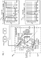
- a microscope assembly 145 comprising a beam splitter assembly 100 is shown.
- the beam splitter assembly 100 allows to take and record images of an area in which surgery is performed.
- Three cameras 181, 182, 183 are present that are suitable for recording images of different spectral portions 110, 120, 130.
- fluorescences from different fluorophores can be imaged separately.
- the images acquired in this way can then be input into an image processing device 146 of the microscope assembly and be combined as desired.
- image processing device 146 of the microscope assembly can then be input into an image processing device 146 of the microscope assembly and be combined as desired.
- two or three images can be overlaid and combined into a single image in which characteristic tissue can be seen by a surgeon.
- the intensities of the signals of the fluorophores might be adjusted as desired and for example be displayed with false colors to allow an easy differentiation.
- Such an image can then be displayed on a display device 148 or viewed in a viewing system.
- the optical beam splitter assembly 100 comprises a first beam splitter 151 and a second beam splitter 152.
- the two beam splitters 151, 152 serve to split the light into a first light path 171, a second light path 172, and a third light path 173.
- the first light path 171 is configured to guide light of a first spectral portion 110 from a light entrance section 160, at which the light enters the optical beam splitter assembly 100, to a first light output section 161.
- the second light path 172 is configured to guide light of a second spectral portion 120 from the light entrance section 160 to a second light output section 162, the second light output section 162 being spaced apart from the first light output section 161.
- the third light path 173 is configured to guide light of a third spectral portion 130 from the light entrance section 160 to a third light output section 163, the third light output section 163 being spaced apart from the first light output section 161 and the second light output section 162.
- the second light path 172 traverses the first beam splitter 151
- the third light path 173 traverses the first and the second beam splitter 151, 152.
- the beam splitters 151, 152 can be each embodied as dichroic mirrors 155.
- Each dichroic mirrors 155 comprises at least one thin layer that reflects a predefined wavelength under a certain angle. Other wavelengths can be transmitted.
- the first beam splitter 151 reflects light of the first spectral portion 110 along the first light path 171.
- the first beam splitter 151 transmits light of the second spectral portion 120 and further wavelengths that are not part of the first spectral portion 110.
- the second beam splitter 152 reflects light of the second spectral portion 120 along the second light path 172 and can for example transmit other wavelengths. As no or almost no light of the first spectral portion 110 arrives at the second beam splitter 152, it could however also reflect light of the first spectral portion 110.
- the optical beam splitter assembly 100 comprises three cameras 181, 182, 182 having three image sensors 181a, 182a, 183a for detecting the light at the first, second and third output section 161, 162, 163. To this end, the three image sensors 181a, 182a, 183a are arranged at the first, second or third output section 161, 162, 163, respectively.
- an emission band of a fluorophore overlaps with the spectral portion 110, 120.
- fluorescein, 5-ALA and ICG can be used as a fluorophore.
- the spectral portion 110 of the light guided by the first light path 171 comprises two spectral subportions 111, 112 spaced apart from each other. This can be, for example, achieved by a first beam splitter 151 that reflects two spectral subportions and guides them onto the first image sensor 181a of the first camera 181 located at the first light output section 161.
- a fluorescence emission band of a fluorophore overlaps with the spectral subportion 111, 112 or lies within the spectral subportion 111, 112.
- the first spectral subportion 111 associated with fluorescein is located around the typical fluorescence emission wavelength of 540 nm.
- the second spectral subportion 112 associated with ICG comprises wavelengths of around 750-900 nm.
- the first camera 181 comprises a Bayer filter 188a.
- the Bayer filter 188a comprises three subfilters for selectively transmitting only one of red, green and blue onto each pixel.
- the area of the green subfilter comprises the combined area of the red and the blue subfilter.
- a subfilter of the Bayer filter 188a can be selected to match to a fluorescence emission band of one of the fluorophores.
- a maximum of the transmittance of the subfilter can be located within 50 nm, preferably 20 nm of the fluorescence emission band maximum.
- a transmittance of the subfilter at the wavelength of the maximum of the fluorescence emission band can be more than 80 percent, preferably more than 90 percent, even more preferably at least 95 percent.
- a fluorophore is selected so that its fluorescence emission band overlaps with the spectral portion transmitted by a subfilter of the Bayer filter 188a.
- the second camera 182 comprises a black-and-white image sensor 182a, but not a Bayer filter. This can for example be useful when a weak signal or a fluorophore with a low quantum efficiency is used.
- the second light path 172 can be associated with a spectral portion 120 relating to a fluorescence emission of 5-ALA.
- the third camera 183 can comprise a Bayer filter 188b and a third image sensor 183a in order to record the third spectral portion 130 of remaining light which has a broad spectral range and can be denominated white light.
- This third spectral portion 130 can be used to give a general overview of the area in which surgery is performed.
- the optical beam splitter assembly 100 comprises three cameras 181, 182, 183, one camera 182 being a black-and-white camera with a black-and-white image sensor 189 and two cameras 181, 183 comprising Bayer filters 188a, 188b.
- the two cameras 181, 183 comprising Bayer filters 188a, 188b can also comprise black-and-white image sensors 189 behind the Bayer filters 188a, 188b.
- the two cameras 181, 183 can be color cameras that allow to take images with color information.
- the black-and-white image sensor 182a, 189 of the black-and-white camera 182 is arranged at the second light output section 162 and the image sensors 181a, 183a of the cameras 181, 183 with the Bayer filters 188a, 188b are arranged at the first and the third light output sections 161, 163.
- a black-and-white image sensor 189 and/or a black-and-white camera could be arranged at the first output section 161 to avoid any loss due to the first beam splitter 151.
- the camera 181 associated with the first light output section 161 is configured to record a color image in an RGB color space, the color space having a predetermined set of color channels.
- the spectral portion 110 of the first light path 171 comprises two spectral subportions 111, 112, wherein a first subportion 111, namely the one associated with fluorescein, overlaps with a first color channel, namely green, of the color space but not a second color channel, namely red of the color space.
- the second subportion 112, namely one related with ICG overlaps at least with the second color channel, namely red.
- the two color channels can be separated by another color channel.
- Each of the color channels can be a primary color, for example red, green or blue.
- the reflected spectral portion 120 recorded by the second image sensor 182a associated with the second light output section 162 lies between the two spectral subportions 111, 112 recorded at the first light output section 161.
- the first and the second spectral portion 110, 120 do not overlap.
- optical beam splitter assembly is configured to guide white light or remaining light to the third output section 163.
- the optical beam splitter assembly 100 is configured for guiding light of two fluorescence emission bands with a first and a second wavelength to the first light output section 161 and light of a fluorescence emission band with a third wavelength between the first and the second wavelength to the second light output section 162.
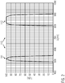
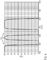
- Figs. 2 to 4 The resulting distribution of the different spectral portions can be seen in Figs. 2 to 4 .
- light with wavelengths below approximately 900 nm enters the optical beam splitter assembly 100 through the light entrance section 160.
- the fluorescein band and the ICG band are directed towards the first camera 181 by the first beam splitter 151 and can in Fig. 2 be seen as two distinct peaks in the spectrum with a gap between the two peaks.
- the 5-ALA peak is transmitted through the first beam splitter 151 and directed by the second beam splitter 152 towards the second camera 182. Due to the lack of a (Bayer) filter in the second camera 182, a high sensitivity can be achieved for this weak signal. As can be seen in Fig. 3 , this peak is located between the two peaks measured at the first output section. This spatial separation of the peaks allows a good separation and reliable detection of the signals.
- Fig. 4 the portion of the light that arrives at the third output section 163 is shown. This is the light that enters the input section and is neither deflected towards the first output section 161 nor towards the second output section 162 nor absorbed. Due to the width of the spectrum, this portion can be named white light.
- an image sensor 182a and/or a camera 182 associated with the second output section 162 could be configured to record a color image in a color space, the color space having a predetermined set of color channels and the spectral portion 120 of the second light path 172 comprises two spectral subportions wherein a first subportion overlaps with a first color channel of the color space and not a second color channel of the color space, wherein a second subportion overlaps at least with the second color channel.
- the optical beam splitter assembly is configured for guiding light of two fluorescence emission bands with a first and a second wavelength to the second light output section 162 and light of a fluorescence emission band with a third wavelength between the first and the second wavelength to the first light output section 161.
- the two beam splitters 151, 152 each comprise a coating 195 on a prism 191, 192, 193.
- the optical beam splitter assembly 100 comprises a first prism 191 comprising the light entrance section 160 and the first light output section 161, a second prism 192 comprising the second light output section 162, and a third prism 193 comprising the third light output section 163.
- the first beam splitter 151 is between the first prism 191 and the second prism 192. Moreover, the second beam splitter 152 is between the second prism 192 and the third prism 193.
- the optical beam splitter assembly 100 comprises three prisms 191, 192, 193 that are connected to each other to form a unitary block 199. This can simplify the handling.
- the optical beam splitter assembly 100 can be part of a camera head 140 of the microscope assembly 145 or the microscope.
- the optical beam splitter assembly 100 is configured for the combined use of fluorescein, ICG and 5-ALA. This is achieved as the first subportion 111 and the second subportion 112 of the first portion 110 and the second portion 120 are such that each of them overlaps with one fluorescence emission band of fluorescein, ICG and 5-ALA but not with the fluorescence emission bands of the other fluorophores.
- aspects have been described in the context of an apparatus, it is clear that these aspects also represent a description of the corresponding method, where a block or device corresponds to a method step or a feature of a method step. Analogously, aspects described in the context of a method step also represent a description of a corresponding block or item or feature of a corresponding apparatus.
- Some or all of the method steps may be executed by (or using) a hardware apparatus, such as for example, a processor, a microprocessor, a programmable computer or an electronic circuit. In some embodiments, one or more of the most important method steps may be executed by such an apparatus.
- embodiments of the invention can be implemented in hardware or in software.
- the implementation can be performed using a non-transitory storage medium such as a digital storage medium, for example a floppy disc, a DVD, a Blu-Ray, a CD, a ROM, a PROM, and EPROM, an EEPROM or a FLASH memory, having electronically readable control signals stored thereon, which cooperate (or are capable of cooperating) with a programmable computer system such that the respective method is performed. Therefore, the digital storage medium may be computer readable.
- Some embodiments according to the invention comprise a data carrier having electronically readable control signals, which are capable of cooperating with a programmable computer system, such that one of the methods described herein is performed.
- embodiments of the present invention can be implemented as a computer program product with a program code, the program code being operative for performing one of the methods when the computer program product runs on a computer.
- the program code may, for example, be stored on a machine readable carrier.
- inventions comprise the computer program for performing one of the methods described herein, stored on a machine readable carrier.
- an embodiment of the present invention is, therefore, a computer program having a program code for performing one of the methods described herein, when the computer program runs on a computer.
- a further embodiment of the present invention is, therefore, a storage medium (or a data carrier, or a computer-readable medium) comprising, stored thereon, the computer program for performing one of the methods described herein when it is performed by a processor.
- the data carrier, the digital storage medium or the recorded medium are typically tangible and/or non-transitionary.
- a further embodiment of the present invention is an apparatus as described herein comprising a processor and the storage medium.
- a further embodiment of the invention is, therefore, a data stream or a sequence of signals representing the computer program for performing one of the methods described herein.
- the data stream or the sequence of signals may, for example, be configured to be transferred via a data communication connection, for example, via the internet.
- a further embodiment comprises a processing means, for example, a computer or a programmable logic device, configured to, or adapted to, perform one of the methods described herein.
- a processing means for example, a computer or a programmable logic device, configured to, or adapted to, perform one of the methods described herein.
- a further embodiment comprises a computer having installed thereon the computer program for performing one of the methods described herein.
- a further embodiment according to the invention comprises an apparatus or a system configured to transfer (for example, electronically or optically) a computer program for performing one of the methods described herein to a receiver.
- the receiver may, for example, be a computer, a mobile device, a memory device or the like.
- the apparatus or system may, for example, comprise a file server for transferring the computer program to the receiver.
- a programmable logic device for example, a field programmable gate array
- a field programmable gate array may cooperate with a microprocessor in order to perform one of the methods described herein.
- the methods are preferably performed by any hardware apparatus.
Landscapes
- Physics & Mathematics (AREA)
- General Physics & Mathematics (AREA)
- Optics & Photonics (AREA)
- Spectroscopy & Molecular Physics (AREA)
- Chemical & Material Sciences (AREA)
- Analytical Chemistry (AREA)
- Microscoopes, Condenser (AREA)
- Investigating, Analyzing Materials By Fluorescence Or Luminescence (AREA)
- Optical Elements Other Than Lenses (AREA)
- Optical Filters (AREA)
Priority Applications (3)
| Application Number | Priority Date | Filing Date | Title |
|---|---|---|---|
| EP19191816.8A EP3779554B1 (de) | 2019-08-14 | 2019-08-14 | Optische strahlteileranordnung, kamerakopf und mikroskopanordnung |
| JP2022508838A JP7483862B2 (ja) | 2019-08-14 | 2020-08-14 | 光ビームスプリッタアセンブリ、カメラヘッドおよび顕微鏡アセンブリ |
| PCT/EP2020/072883 WO2021028576A1 (en) | 2019-08-14 | 2020-08-14 | Optical beam splitter assembly, camera head, and microscope assembly |
Applications Claiming Priority (1)
| Application Number | Priority Date | Filing Date | Title |
|---|---|---|---|
| EP19191816.8A EP3779554B1 (de) | 2019-08-14 | 2019-08-14 | Optische strahlteileranordnung, kamerakopf und mikroskopanordnung |
Publications (2)
| Publication Number | Publication Date |
|---|---|
| EP3779554A1 true EP3779554A1 (de) | 2021-02-17 |
| EP3779554B1 EP3779554B1 (de) | 2024-01-17 |
Family
ID=67658873
Family Applications (1)
| Application Number | Title | Priority Date | Filing Date |
|---|---|---|---|
| EP19191816.8A Active EP3779554B1 (de) | 2019-08-14 | 2019-08-14 | Optische strahlteileranordnung, kamerakopf und mikroskopanordnung |
Country Status (3)
| Country | Link |
|---|---|
| EP (1) | EP3779554B1 (de) |
| JP (1) | JP7483862B2 (de) |
| WO (1) | WO2021028576A1 (de) |
Citations (4)
| Publication number | Priority date | Publication date | Assignee | Title |
|---|---|---|---|---|
| US9173554B2 (en) * | 2008-03-18 | 2015-11-03 | Novadaq Technologies, Inc. | Imaging system for combined full-color reflectance and near-infrared imaging |
| US20170176336A1 (en) * | 2014-06-05 | 2017-06-22 | Universität Heidelberg | Method and means for multispectral imaging |
| US20190076007A1 (en) * | 2017-09-11 | 2019-03-14 | Panasonic Intellectual Property Management Co., Lt d. | Endoscope and endoscope system |
| US20190170647A1 (en) * | 2016-08-19 | 2019-06-06 | Sony Corporation | Imaging system |
Family Cites Families (3)
| Publication number | Priority date | Publication date | Assignee | Title |
|---|---|---|---|---|
| JPH08275182A (ja) * | 1995-03-28 | 1996-10-18 | Canon Inc | カラーモード・赤外モード共用型テレビカメラ |
| WO2005046248A1 (ja) | 2003-11-11 | 2005-05-19 | Olympus Corporation | マルチスペクトル画像撮影装置 |
| WO2017127929A1 (en) | 2016-01-26 | 2017-08-03 | Novadaq Technologies Inc. | Configurable platform |
-
2019
- 2019-08-14 EP EP19191816.8A patent/EP3779554B1/de active Active
-
2020
- 2020-08-14 WO PCT/EP2020/072883 patent/WO2021028576A1/en not_active Ceased
- 2020-08-14 JP JP2022508838A patent/JP7483862B2/ja active Active
Patent Citations (4)
| Publication number | Priority date | Publication date | Assignee | Title |
|---|---|---|---|---|
| US9173554B2 (en) * | 2008-03-18 | 2015-11-03 | Novadaq Technologies, Inc. | Imaging system for combined full-color reflectance and near-infrared imaging |
| US20170176336A1 (en) * | 2014-06-05 | 2017-06-22 | Universität Heidelberg | Method and means for multispectral imaging |
| US20190170647A1 (en) * | 2016-08-19 | 2019-06-06 | Sony Corporation | Imaging system |
| US20190076007A1 (en) * | 2017-09-11 | 2019-03-14 | Panasonic Intellectual Property Management Co., Lt d. | Endoscope and endoscope system |
Also Published As
| Publication number | Publication date |
|---|---|
| WO2021028576A1 (en) | 2021-02-18 |
| JP7483862B2 (ja) | 2024-05-15 |
| EP3779554B1 (de) | 2024-01-17 |
| JP2022544387A (ja) | 2022-10-18 |
Similar Documents
| Publication | Publication Date | Title |
|---|---|---|
| US10419693B2 (en) | Imaging apparatus, endoscope apparatus, and microscope apparatus | |
| NL2018494B1 (en) | Method and apparatus using a medical imaging head for fluorescent imaging | |
| US11555993B2 (en) | Concept for a microscope system with an LED-based illumination system | |
| US10721411B2 (en) | Smart photonic imaging method and apparatus | |
| US9389120B2 (en) | Spectral detector or laser scanning microscope having variable filtration using spatial color separation | |
| AU2011307151B2 (en) | Digital multi-spectral camera system having at least two independent digital cameras | |
| US10852526B2 (en) | Objective optical system and endoscope apparatus using the same | |
| JP2018160800A (ja) | 撮像装置及び撮像方法 | |
| US20200126220A1 (en) | Surgical imaging system and signal processing device of surgical image | |
| US9091653B2 (en) | Microscope and method for wavelength-selective and high spatial resolving microscopy | |
| JP5414369B2 (ja) | 眼底カメラ及び制御方法 | |
| EP3779554B1 (de) | Optische strahlteileranordnung, kamerakopf und mikroskopanordnung | |
| JP2907571B2 (ja) | レーザ走査型蛍光顕微鏡 | |
| JP4411109B2 (ja) | 3次元領域内の被写体の撮影方法および撮影装置 | |
| JP2020099694A (ja) | 特に顕微鏡および内視鏡のための、蛍光発光性蛍光体のhdrモノクローム画像を作成するためのシステムおよび方法 | |
| EP4064673B1 (de) | Bildgebungsvorrichtung für ein medizinisches bildgebungssystem, medizinisches bildgebungssystem und verfahren zur erzeugung medizinischer bilder | |
| JP2007298279A (ja) | 色測定装置 | |
| US12619060B2 (en) | Microscope system and corresponding method | |
| US12089897B2 (en) | Systems and methods for multiplexing and alternating light of different wavelengths in an ophthalmoscope | |
| JP2025517201A (ja) | 均一な色空間を使用して2つの画像とオーバーレイ色とを組み合わせるデータ処理装置およびコンピュータ実装方法 | |
| CN118915300A (zh) | 一种光学色散补偿方法及装置 | |
| HK40033050A (en) | Time correlated source modulation for endoscopy | |
| JPH0792267A (ja) | 信号光抽出装置 | |
| WO2015166267A1 (en) | Imaging techniques | |
| HK1144964A (en) | Laser-exciting fluorescence microscope |
Legal Events
| Date | Code | Title | Description |
|---|---|---|---|
| PUAI | Public reference made under article 153(3) epc to a published international application that has entered the european phase |
Free format text: ORIGINAL CODE: 0009012 |
|
| STAA | Information on the status of an ep patent application or granted ep patent |
Free format text: STATUS: THE APPLICATION HAS BEEN PUBLISHED |
|
| AK | Designated contracting states |
Kind code of ref document: A1 Designated state(s): AL AT BE BG CH CY CZ DE DK EE ES FI FR GB GR HR HU IE IS IT LI LT LU LV MC MK MT NL NO PL PT RO RS SE SI SK SM TR |
|
| AX | Request for extension of the european patent |
Extension state: BA ME |
|
| STAA | Information on the status of an ep patent application or granted ep patent |
Free format text: STATUS: REQUEST FOR EXAMINATION WAS MADE |
|
| 17P | Request for examination filed |
Effective date: 20210817 |
|
| RBV | Designated contracting states (corrected) |
Designated state(s): AL AT BE BG CH CY CZ DE DK EE ES FI FR GB GR HR HU IE IS IT LI LT LU LV MC MK MT NL NO PL PT RO RS SE SI SK SM TR |
|
| GRAP | Despatch of communication of intention to grant a patent |
Free format text: ORIGINAL CODE: EPIDOSNIGR1 |
|
| STAA | Information on the status of an ep patent application or granted ep patent |
Free format text: STATUS: GRANT OF PATENT IS INTENDED |
|
| INTG | Intention to grant announced |
Effective date: 20230228 |
|
| P01 | Opt-out of the competence of the unified patent court (upc) registered |
Effective date: 20230414 |
|
| GRAJ | Information related to disapproval of communication of intention to grant by the applicant or resumption of examination proceedings by the epo deleted |
Free format text: ORIGINAL CODE: EPIDOSDIGR1 |
|
| STAA | Information on the status of an ep patent application or granted ep patent |
Free format text: STATUS: REQUEST FOR EXAMINATION WAS MADE |
|
| INTC | Intention to grant announced (deleted) | ||
| GRAP | Despatch of communication of intention to grant a patent |
Free format text: ORIGINAL CODE: EPIDOSNIGR1 |
|
| STAA | Information on the status of an ep patent application or granted ep patent |
Free format text: STATUS: GRANT OF PATENT IS INTENDED |
|
| INTG | Intention to grant announced |
Effective date: 20230818 |
|
| GRAS | Grant fee paid |
Free format text: ORIGINAL CODE: EPIDOSNIGR3 |
|
| GRAA | (expected) grant |
Free format text: ORIGINAL CODE: 0009210 |
|
| STAA | Information on the status of an ep patent application or granted ep patent |
Free format text: STATUS: THE PATENT HAS BEEN GRANTED |
|
| AK | Designated contracting states |
Kind code of ref document: B1 Designated state(s): AL AT BE BG CH CY CZ DE DK EE ES FI FR GB GR HR HU IE IS IT LI LT LU LV MC MK MT NL NO PL PT RO RS SE SI SK SM TR |
|
| REG | Reference to a national code |
Ref country code: GB Ref legal event code: FG4D |
|
| REG | Reference to a national code |
Ref country code: DE Ref legal event code: R096 Ref document number: 602019045143 Country of ref document: DE |
|
| REG | Reference to a national code |
Ref country code: CH Ref legal event code: EP |
|
| REG | Reference to a national code |
Ref country code: IE Ref legal event code: FG4D |
|
| REG | Reference to a national code |
Ref country code: LT Ref legal event code: MG9D |
|
| REG | Reference to a national code |
Ref country code: NL Ref legal event code: MP Effective date: 20240117 |
|
| REG | Reference to a national code |
Ref country code: AT Ref legal event code: MK05 Ref document number: 1650905 Country of ref document: AT Kind code of ref document: T Effective date: 20240117 |
|
| PG25 | Lapsed in a contracting state [announced via postgrant information from national office to epo] |
Ref country code: NL Free format text: LAPSE BECAUSE OF FAILURE TO SUBMIT A TRANSLATION OF THE DESCRIPTION OR TO PAY THE FEE WITHIN THE PRESCRIBED TIME-LIMIT Effective date: 20240117 |
|
| PG25 | Lapsed in a contracting state [announced via postgrant information from national office to epo] |
Ref country code: NL Free format text: LAPSE BECAUSE OF FAILURE TO SUBMIT A TRANSLATION OF THE DESCRIPTION OR TO PAY THE FEE WITHIN THE PRESCRIBED TIME-LIMIT Effective date: 20240117 |
|
| PG25 | Lapsed in a contracting state [announced via postgrant information from national office to epo] |
Ref country code: IS Free format text: LAPSE BECAUSE OF FAILURE TO SUBMIT A TRANSLATION OF THE DESCRIPTION OR TO PAY THE FEE WITHIN THE PRESCRIBED TIME-LIMIT Effective date: 20240517 |
|
| PG25 | Lapsed in a contracting state [announced via postgrant information from national office to epo] |
Ref country code: LT Free format text: LAPSE BECAUSE OF FAILURE TO SUBMIT A TRANSLATION OF THE DESCRIPTION OR TO PAY THE FEE WITHIN THE PRESCRIBED TIME-LIMIT Effective date: 20240117 |
|
| PG25 | Lapsed in a contracting state [announced via postgrant information from national office to epo] |
Ref country code: GR Free format text: LAPSE BECAUSE OF FAILURE TO SUBMIT A TRANSLATION OF THE DESCRIPTION OR TO PAY THE FEE WITHIN THE PRESCRIBED TIME-LIMIT Effective date: 20240418 |
|
| PG25 | Lapsed in a contracting state [announced via postgrant information from national office to epo] |
Ref country code: RS Free format text: LAPSE BECAUSE OF FAILURE TO SUBMIT A TRANSLATION OF THE DESCRIPTION OR TO PAY THE FEE WITHIN THE PRESCRIBED TIME-LIMIT Effective date: 20240417 Ref country code: HR Free format text: LAPSE BECAUSE OF FAILURE TO SUBMIT A TRANSLATION OF THE DESCRIPTION OR TO PAY THE FEE WITHIN THE PRESCRIBED TIME-LIMIT Effective date: 20240117 |
|
| PG25 | Lapsed in a contracting state [announced via postgrant information from national office to epo] |
Ref country code: ES Free format text: LAPSE BECAUSE OF FAILURE TO SUBMIT A TRANSLATION OF THE DESCRIPTION OR TO PAY THE FEE WITHIN THE PRESCRIBED TIME-LIMIT Effective date: 20240117 |
|
| PG25 | Lapsed in a contracting state [announced via postgrant information from national office to epo] |
Ref country code: AT Free format text: LAPSE BECAUSE OF FAILURE TO SUBMIT A TRANSLATION OF THE DESCRIPTION OR TO PAY THE FEE WITHIN THE PRESCRIBED TIME-LIMIT Effective date: 20240117 |
|
| PG25 | Lapsed in a contracting state [announced via postgrant information from national office to epo] |
Ref country code: RS Free format text: LAPSE BECAUSE OF FAILURE TO SUBMIT A TRANSLATION OF THE DESCRIPTION OR TO PAY THE FEE WITHIN THE PRESCRIBED TIME-LIMIT Effective date: 20240417 Ref country code: NO Free format text: LAPSE BECAUSE OF FAILURE TO SUBMIT A TRANSLATION OF THE DESCRIPTION OR TO PAY THE FEE WITHIN THE PRESCRIBED TIME-LIMIT Effective date: 20240417 Ref country code: LT Free format text: LAPSE BECAUSE OF FAILURE TO SUBMIT A TRANSLATION OF THE DESCRIPTION OR TO PAY THE FEE WITHIN THE PRESCRIBED TIME-LIMIT Effective date: 20240117 Ref country code: IS Free format text: LAPSE BECAUSE OF FAILURE TO SUBMIT A TRANSLATION OF THE DESCRIPTION OR TO PAY THE FEE WITHIN THE PRESCRIBED TIME-LIMIT Effective date: 20240517 Ref country code: HR Free format text: LAPSE BECAUSE OF FAILURE TO SUBMIT A TRANSLATION OF THE DESCRIPTION OR TO PAY THE FEE WITHIN THE PRESCRIBED TIME-LIMIT Effective date: 20240117 Ref country code: GR Free format text: LAPSE BECAUSE OF FAILURE TO SUBMIT A TRANSLATION OF THE DESCRIPTION OR TO PAY THE FEE WITHIN THE PRESCRIBED TIME-LIMIT Effective date: 20240418 Ref country code: FI Free format text: LAPSE BECAUSE OF FAILURE TO SUBMIT A TRANSLATION OF THE DESCRIPTION OR TO PAY THE FEE WITHIN THE PRESCRIBED TIME-LIMIT Effective date: 20240117 Ref country code: ES Free format text: LAPSE BECAUSE OF FAILURE TO SUBMIT A TRANSLATION OF THE DESCRIPTION OR TO PAY THE FEE WITHIN THE PRESCRIBED TIME-LIMIT Effective date: 20240117 Ref country code: BG Free format text: LAPSE BECAUSE OF FAILURE TO SUBMIT A TRANSLATION OF THE DESCRIPTION OR TO PAY THE FEE WITHIN THE PRESCRIBED TIME-LIMIT Effective date: 20240117 Ref country code: AT Free format text: LAPSE BECAUSE OF FAILURE TO SUBMIT A TRANSLATION OF THE DESCRIPTION OR TO PAY THE FEE WITHIN THE PRESCRIBED TIME-LIMIT Effective date: 20240117 |
|
| PG25 | Lapsed in a contracting state [announced via postgrant information from national office to epo] |
Ref country code: PL Free format text: LAPSE BECAUSE OF FAILURE TO SUBMIT A TRANSLATION OF THE DESCRIPTION OR TO PAY THE FEE WITHIN THE PRESCRIBED TIME-LIMIT Effective date: 20240117 Ref country code: PT Free format text: LAPSE BECAUSE OF FAILURE TO SUBMIT A TRANSLATION OF THE DESCRIPTION OR TO PAY THE FEE WITHIN THE PRESCRIBED TIME-LIMIT Effective date: 20240517 |
|
| PG25 | Lapsed in a contracting state [announced via postgrant information from national office to epo] |
Ref country code: SE Free format text: LAPSE BECAUSE OF FAILURE TO SUBMIT A TRANSLATION OF THE DESCRIPTION OR TO PAY THE FEE WITHIN THE PRESCRIBED TIME-LIMIT Effective date: 20240117 Ref country code: PT Free format text: LAPSE BECAUSE OF FAILURE TO SUBMIT A TRANSLATION OF THE DESCRIPTION OR TO PAY THE FEE WITHIN THE PRESCRIBED TIME-LIMIT Effective date: 20240517 Ref country code: PL Free format text: LAPSE BECAUSE OF FAILURE TO SUBMIT A TRANSLATION OF THE DESCRIPTION OR TO PAY THE FEE WITHIN THE PRESCRIBED TIME-LIMIT Effective date: 20240117 Ref country code: LV Free format text: LAPSE BECAUSE OF FAILURE TO SUBMIT A TRANSLATION OF THE DESCRIPTION OR TO PAY THE FEE WITHIN THE PRESCRIBED TIME-LIMIT Effective date: 20240117 |
|
| PG25 | Lapsed in a contracting state [announced via postgrant information from national office to epo] |
Ref country code: DK Free format text: LAPSE BECAUSE OF FAILURE TO SUBMIT A TRANSLATION OF THE DESCRIPTION OR TO PAY THE FEE WITHIN THE PRESCRIBED TIME-LIMIT Effective date: 20240117 |
|
| PG25 | Lapsed in a contracting state [announced via postgrant information from national office to epo] |
Ref country code: SM Free format text: LAPSE BECAUSE OF FAILURE TO SUBMIT A TRANSLATION OF THE DESCRIPTION OR TO PAY THE FEE WITHIN THE PRESCRIBED TIME-LIMIT Effective date: 20240117 |
|
| REG | Reference to a national code |
Ref country code: DE Ref legal event code: R097 Ref document number: 602019045143 Country of ref document: DE |
|
| PG25 | Lapsed in a contracting state [announced via postgrant information from national office to epo] |
Ref country code: EE Free format text: LAPSE BECAUSE OF FAILURE TO SUBMIT A TRANSLATION OF THE DESCRIPTION OR TO PAY THE FEE WITHIN THE PRESCRIBED TIME-LIMIT Effective date: 20240117 Ref country code: CZ Free format text: LAPSE BECAUSE OF FAILURE TO SUBMIT A TRANSLATION OF THE DESCRIPTION OR TO PAY THE FEE WITHIN THE PRESCRIBED TIME-LIMIT Effective date: 20240117 |
|
| PG25 | Lapsed in a contracting state [announced via postgrant information from national office to epo] |
Ref country code: SK Free format text: LAPSE BECAUSE OF FAILURE TO SUBMIT A TRANSLATION OF THE DESCRIPTION OR TO PAY THE FEE WITHIN THE PRESCRIBED TIME-LIMIT Effective date: 20240117 |
|
| PG25 | Lapsed in a contracting state [announced via postgrant information from national office to epo] |
Ref country code: SM Free format text: LAPSE BECAUSE OF FAILURE TO SUBMIT A TRANSLATION OF THE DESCRIPTION OR TO PAY THE FEE WITHIN THE PRESCRIBED TIME-LIMIT Effective date: 20240117 Ref country code: SK Free format text: LAPSE BECAUSE OF FAILURE TO SUBMIT A TRANSLATION OF THE DESCRIPTION OR TO PAY THE FEE WITHIN THE PRESCRIBED TIME-LIMIT Effective date: 20240117 Ref country code: RO Free format text: LAPSE BECAUSE OF FAILURE TO SUBMIT A TRANSLATION OF THE DESCRIPTION OR TO PAY THE FEE WITHIN THE PRESCRIBED TIME-LIMIT Effective date: 20240117 Ref country code: EE Free format text: LAPSE BECAUSE OF FAILURE TO SUBMIT A TRANSLATION OF THE DESCRIPTION OR TO PAY THE FEE WITHIN THE PRESCRIBED TIME-LIMIT Effective date: 20240117 Ref country code: DK Free format text: LAPSE BECAUSE OF FAILURE TO SUBMIT A TRANSLATION OF THE DESCRIPTION OR TO PAY THE FEE WITHIN THE PRESCRIBED TIME-LIMIT Effective date: 20240117 Ref country code: CZ Free format text: LAPSE BECAUSE OF FAILURE TO SUBMIT A TRANSLATION OF THE DESCRIPTION OR TO PAY THE FEE WITHIN THE PRESCRIBED TIME-LIMIT Effective date: 20240117 |
|
| PLBE | No opposition filed within time limit |
Free format text: ORIGINAL CODE: 0009261 |
|
| STAA | Information on the status of an ep patent application or granted ep patent |
Free format text: STATUS: NO OPPOSITION FILED WITHIN TIME LIMIT |
|
| PG25 | Lapsed in a contracting state [announced via postgrant information from national office to epo] |
Ref country code: IT Free format text: LAPSE BECAUSE OF FAILURE TO SUBMIT A TRANSLATION OF THE DESCRIPTION OR TO PAY THE FEE WITHIN THE PRESCRIBED TIME-LIMIT Effective date: 20240117 |
|
| 26N | No opposition filed |
Effective date: 20241018 |
|
| PG25 | Lapsed in a contracting state [announced via postgrant information from national office to epo] |
Ref country code: IT Free format text: LAPSE BECAUSE OF FAILURE TO SUBMIT A TRANSLATION OF THE DESCRIPTION OR TO PAY THE FEE WITHIN THE PRESCRIBED TIME-LIMIT Effective date: 20240117 |
|
| REG | Reference to a national code |
Ref country code: CH Ref legal event code: PL |
|
| PG25 | Lapsed in a contracting state [announced via postgrant information from national office to epo] |
Ref country code: LU Free format text: LAPSE BECAUSE OF NON-PAYMENT OF DUE FEES Effective date: 20240814 |
|
| PG25 | Lapsed in a contracting state [announced via postgrant information from national office to epo] |
Ref country code: SI Free format text: LAPSE BECAUSE OF FAILURE TO SUBMIT A TRANSLATION OF THE DESCRIPTION OR TO PAY THE FEE WITHIN THE PRESCRIBED TIME-LIMIT Effective date: 20240117 Ref country code: CH Free format text: LAPSE BECAUSE OF NON-PAYMENT OF DUE FEES Effective date: 20240831 Ref country code: MC Free format text: LAPSE BECAUSE OF FAILURE TO SUBMIT A TRANSLATION OF THE DESCRIPTION OR TO PAY THE FEE WITHIN THE PRESCRIBED TIME-LIMIT Effective date: 20240117 |
|
| REG | Reference to a national code |
Ref country code: BE Ref legal event code: MM Effective date: 20240831 |
|
| PG25 | Lapsed in a contracting state [announced via postgrant information from national office to epo] |
Ref country code: BE Free format text: LAPSE BECAUSE OF NON-PAYMENT OF DUE FEES Effective date: 20240831 |
|
| PG25 | Lapsed in a contracting state [announced via postgrant information from national office to epo] |
Ref country code: IE Free format text: LAPSE BECAUSE OF NON-PAYMENT OF DUE FEES Effective date: 20240814 |
|
| PGFP | Annual fee paid to national office [announced via postgrant information from national office to epo] |
Ref country code: DE Payment date: 20250827 Year of fee payment: 7 |
|
| PGFP | Annual fee paid to national office [announced via postgrant information from national office to epo] |
Ref country code: GB Payment date: 20250826 Year of fee payment: 7 |
|
| PGFP | Annual fee paid to national office [announced via postgrant information from national office to epo] |
Ref country code: FR Payment date: 20250825 Year of fee payment: 7 |
|
| PG25 | Lapsed in a contracting state [announced via postgrant information from national office to epo] |
Ref country code: CY Free format text: LAPSE BECAUSE OF FAILURE TO SUBMIT A TRANSLATION OF THE DESCRIPTION OR TO PAY THE FEE WITHIN THE PRESCRIBED TIME-LIMIT; INVALID AB INITIO Effective date: 20190814 |
|
| PG25 | Lapsed in a contracting state [announced via postgrant information from national office to epo] |
Ref country code: HU Free format text: LAPSE BECAUSE OF FAILURE TO SUBMIT A TRANSLATION OF THE DESCRIPTION OR TO PAY THE FEE WITHIN THE PRESCRIBED TIME-LIMIT; INVALID AB INITIO Effective date: 20190814 |