EP3778457A1 - Film wrinkle removing roller - Google Patents
Film wrinkle removing roller Download PDFInfo
- Publication number
- EP3778457A1 EP3778457A1 EP19804123.8A EP19804123A EP3778457A1 EP 3778457 A1 EP3778457 A1 EP 3778457A1 EP 19804123 A EP19804123 A EP 19804123A EP 3778457 A1 EP3778457 A1 EP 3778457A1
- Authority
- EP
- European Patent Office
- Prior art keywords
- film
- roll
- pattern
- pattern rolls
- removing roller
- Prior art date
- Legal status (The legal status is an assumption and is not a legal conclusion. Google has not performed a legal analysis and makes no representation as to the accuracy of the status listed.)
- Granted
Links
Images


Classifications
-
- B—PERFORMING OPERATIONS; TRANSPORTING
- B65—CONVEYING; PACKING; STORING; HANDLING THIN OR FILAMENTARY MATERIAL
- B65H—HANDLING THIN OR FILAMENTARY MATERIAL, e.g. SHEETS, WEBS, CABLES
- B65H23/00—Registering, tensioning, smoothing or guiding webs
- B65H23/02—Registering, tensioning, smoothing or guiding webs transversely
- B65H23/022—Registering, tensioning, smoothing or guiding webs transversely by tentering devices
- B65H23/025—Registering, tensioning, smoothing or guiding webs transversely by tentering devices by rollers
-
- B—PERFORMING OPERATIONS; TRANSPORTING
- B65—CONVEYING; PACKING; STORING; HANDLING THIN OR FILAMENTARY MATERIAL
- B65H—HANDLING THIN OR FILAMENTARY MATERIAL, e.g. SHEETS, WEBS, CABLES
- B65H23/00—Registering, tensioning, smoothing or guiding webs
- B65H23/02—Registering, tensioning, smoothing or guiding webs transversely
- B65H23/022—Registering, tensioning, smoothing or guiding webs transversely by tentering devices
- B65H23/025—Registering, tensioning, smoothing or guiding webs transversely by tentering devices by rollers
- B65H23/0251—Registering, tensioning, smoothing or guiding webs transversely by tentering devices by rollers with a straight axis
-
- B—PERFORMING OPERATIONS; TRANSPORTING
- B65—CONVEYING; PACKING; STORING; HANDLING THIN OR FILAMENTARY MATERIAL
- B65H—HANDLING THIN OR FILAMENTARY MATERIAL, e.g. SHEETS, WEBS, CABLES
- B65H23/00—Registering, tensioning, smoothing or guiding webs
- B65H23/02—Registering, tensioning, smoothing or guiding webs transversely
- B65H23/022—Registering, tensioning, smoothing or guiding webs transversely by tentering devices
- B65H23/025—Registering, tensioning, smoothing or guiding webs transversely by tentering devices by rollers
- B65H23/0251—Registering, tensioning, smoothing or guiding webs transversely by tentering devices by rollers with a straight axis
- B65H23/0256—Registering, tensioning, smoothing or guiding webs transversely by tentering devices by rollers with a straight axis with opposed helicoidal windings
-
- B—PERFORMING OPERATIONS; TRANSPORTING
- B65—CONVEYING; PACKING; STORING; HANDLING THIN OR FILAMENTARY MATERIAL
- B65H—HANDLING THIN OR FILAMENTARY MATERIAL, e.g. SHEETS, WEBS, CABLES
- B65H20/00—Advancing webs
- B65H20/02—Advancing webs by friction roller
-
- B—PERFORMING OPERATIONS; TRANSPORTING
- B65—CONVEYING; PACKING; STORING; HANDLING THIN OR FILAMENTARY MATERIAL
- B65H—HANDLING THIN OR FILAMENTARY MATERIAL, e.g. SHEETS, WEBS, CABLES
- B65H27/00—Special constructions, e.g. surface features, of feed or guide rollers for webs
-
- B—PERFORMING OPERATIONS; TRANSPORTING
- B65—CONVEYING; PACKING; STORING; HANDLING THIN OR FILAMENTARY MATERIAL
- B65H—HANDLING THIN OR FILAMENTARY MATERIAL, e.g. SHEETS, WEBS, CABLES
- B65H2301/00—Handling processes for sheets or webs
- B65H2301/50—Auxiliary process performed during handling process
- B65H2301/51—Modifying a characteristic of handled material
- B65H2301/512—Changing form of handled material
- B65H2301/5125—Restoring form
- B65H2301/51254—Unshirring
-
- B—PERFORMING OPERATIONS; TRANSPORTING
- B65—CONVEYING; PACKING; STORING; HANDLING THIN OR FILAMENTARY MATERIAL
- B65H—HANDLING THIN OR FILAMENTARY MATERIAL, e.g. SHEETS, WEBS, CABLES
- B65H2404/00—Parts for transporting or guiding the handled material
- B65H2404/10—Rollers
-
- B—PERFORMING OPERATIONS; TRANSPORTING
- B65—CONVEYING; PACKING; STORING; HANDLING THIN OR FILAMENTARY MATERIAL
- B65H—HANDLING THIN OR FILAMENTARY MATERIAL, e.g. SHEETS, WEBS, CABLES
- B65H2404/00—Parts for transporting or guiding the handled material
- B65H2404/10—Rollers
- B65H2404/13—Details of longitudinal profile
- B65H2404/132—Details of longitudinal profile arrangement of segments along axis
- B65H2404/1321—Segments juxtaposed along axis
-
- B—PERFORMING OPERATIONS; TRANSPORTING
- B65—CONVEYING; PACKING; STORING; HANDLING THIN OR FILAMENTARY MATERIAL
- B65H—HANDLING THIN OR FILAMENTARY MATERIAL, e.g. SHEETS, WEBS, CABLES
- B65H2404/00—Parts for transporting or guiding the handled material
- B65H2404/10—Rollers
- B65H2404/13—Details of longitudinal profile
- B65H2404/133—Limited number of active elements on common axis
-
- B—PERFORMING OPERATIONS; TRANSPORTING
- B65—CONVEYING; PACKING; STORING; HANDLING THIN OR FILAMENTARY MATERIAL
- B65H—HANDLING THIN OR FILAMENTARY MATERIAL, e.g. SHEETS, WEBS, CABLES
- B65H2701/00—Handled material; Storage means
- B65H2701/10—Handled articles or webs
- B65H2701/13—Parts concerned of the handled material
- B65H2701/132—Side portions
-
- B—PERFORMING OPERATIONS; TRANSPORTING
- B65—CONVEYING; PACKING; STORING; HANDLING THIN OR FILAMENTARY MATERIAL
- B65H—HANDLING THIN OR FILAMENTARY MATERIAL, e.g. SHEETS, WEBS, CABLES
- B65H2701/00—Handled material; Storage means
- B65H2701/10—Handled articles or webs
- B65H2701/17—Nature of material
- B65H2701/175—Plastic
- B65H2701/1752—Polymer film
-
- B—PERFORMING OPERATIONS; TRANSPORTING
- B65—CONVEYING; PACKING; STORING; HANDLING THIN OR FILAMENTARY MATERIAL
- B65H—HANDLING THIN OR FILAMENTARY MATERIAL, e.g. SHEETS, WEBS, CABLES
- B65H2801/00—Application field
- B65H2801/72—Fuel cell manufacture
Definitions
- the present invention relates to a film wrinkle removing roller, and more particularly, to a film wrinkle removing roller in which pattern rolls coated with rubber are positioned at both ends of a cylindrical roll made of Teflon, and a porous film comes into contact with the roll and the pattern rolls, such that the film may be prevented from wrinkling and a surface of the film may be prevented from being abraded due to friction between the film and surfaces of the rolls.
- a porous film is applied as a porous reinforcement base used for a separation membrane for a rechargeable battery and a reinforcement membrane for a fuel cell.
- Examples of the porous film used in this application field include polyethylene (PE), polypropylene (PP), polytetrafluoroethylene (PTFE), and polyethylene terephthalate (PET) films.
- multiple rolls may be used to convey the film during the process of producing the porous film, and these rolls may be made of various materials in accordance with the intended use or characteristics.
- the porous film may be produced through a roll-to-roll film moving process.
- the porous film may wrinkle because tension is applied in a movement direction of the film while the thin porous film moves.
- a process of removing a wrinkle of the film is considered as an important factor among the processes of producing the film, and as a result, an industrial roll capable of improving a wrinkle of the film is being developed.
- a cylindrical roll having a predetermined pattern is provided, and a raw film passes over the cylindrical roll, such that a wrinkle formed on the film is improved.
- the film wrinkle improving rubber roller in the related art has the single pattern roll made of rubber, there is a problem in that an afterimage of a pattern is formed on the surface of the film while the film passes the pattern roll. For this reason, there is a problem in that the surface of the film is not uniformly coated during the film coating.
- An object of the present invention is to provide a film wrinkle removing roller in which a pair of pattern rolls coated with rubber is provided at both ends of a cylindrical roll made of Teflon, and a thin porous film comes into contact with the roll and the pattern rolls, such that an abrasion, which causes an afterimage of a pattern to be formed on a surface of the film by a pattern shape, may be prevented and the surface of the film may be uniformly coated during film coating.
- an object according to an exemplary embodiment of the present invention is to provide a film wrinkle removing roller in which a cylindrical roll, which comes into contact with an effective width of a raw film, is made of Teflon having low frictional force, such that the film passing the roll is unwrinkled in a width direction by pattern rolls, made of rubber, at both ends of the roll while the film passes between the roll and the pattern rolls, and the film may smoothly move without wrinkles, and as a result, productivity of the film may be improved.
- the present invention provides a film wrinkle removing roller including: a roll having a cylindrical shape; a pair of pattern rolls positioned at both ends of the roll and having patterns; and a roll fixing unit configured to fix positions of the roll and the pattern rolls, in which the roll and the pattern rolls are separable from one another and made of materials having different frictional forces.
- the roll may be made of metal and an entire surface of the roll may be coated with Teflon with a predetermined thickness.
- the roll may be made of Teflon.
- the pattern roll may be made of metal and an entire surface of the pattern roll may be coated with rubber with a predetermined thickness.
- the pattern rolls may include first and second pattern rolls disposed at the both ends of the roll, respectively.
- the patterns of the first and second pattern rolls may be formed to be symmetrical to one another.
- the pair of pattern rolls coated with rubber is provided at both ends of the cylindrical roll made of Teflon, and the thin porous film comes into contact with the roll and the pattern rolls, such that an abrasion, which causes an afterimage of a pattern to be formed on the surface of the film, may be prevented and the surface of the film may be uniformly coated during the film coating.
- the cylindrical roll is made of Teflon having low frictional force, such that the film passing the roll is unwrinkled in the width direction by the pattern rolls, made of rubber, at both ends of the roll while the film passes between the roll and the pattern rolls, and the film may smoothly move without wrinkles, and as a result, productivity of the film may be improved.
- FIG. 1 is a view schematically illustrating a structure of a film wrinkle removing roller 100 according to an exemplary embodiment of the present invention
- FIG. 2 is a view schematically illustrating a state in which a film comes into contact with the film wrinkle removing roller 100 according to the exemplary embodiment of the present invention.
- the film wrinkle removing roller 100 may include a cylindrical roll 10, a pair of pattern rolls 20 having patterns, and a roll fixing unit 30 configured to fix positions of the roll 10 and the pattern rolls 20.
- the roll 10 has a cylindrical shape, and an entire surface of the roll 10 may be plain without patterns.
- the roll 10 may be made of metal such as aluminum, copper, or zinc and the entire surface of the roll 10 made of metal may be coated with Teflon (PTFE), or the entire roll 10 may be made of Teflon.
- PTFE Teflon
- the cylindrical roll 10 is made of aluminum, the entire surface of the aluminum roll 10 is coated with Teflon with a predetermined thickness, and then the Teflon is hardened at a hardening temperature, such that surface frictional force of the roll 10 may be minimized.
- the cylindrical roll 10 may come into contact with a porous film (not illustrated).
- the porous film may be used for a separation membrane for a rechargeable battery and a reinforcement membrane of a fuel cell.
- the porous film polyethylene (PE), polypropylene (PP), polytetrafluoroethylene (PTFE), and polyethylene terephthalate (PET) may be applied.
- a length of the roll 10 may be equal to a width (length) of an effective area of the porous film to be in contact with the roll 10, such that damage to the effective area of the surface of the porous film may be prevented and the film may be prevented from being torn.
- the roll 10 is coated with Teflon with a diameter equal to a diameter of the effective area of the porous film, such that a pore structure of the surface of the porous film may be prevented from being deformed when the porous film passes the roll 10.
- the pair of pattern rolls 20 may be positioned at both ends of the cylindrical roll 10, and may include first and second pattern rolls 20a and 20b disposed at the both ends of the roll 10, respectively.
- cylindrical roll 10 and the pair of pattern rolls 20 may be separated from one another and may be made of materials having different frictional forces.
- the pattern roll 20 may be made of metal such as aluminum, copper, or zinc, and the entire surface of the pattern roll 20 made of metal may be coated with rubber with a predetermined thickness.
- the rubber may be styrene-butadiene rubber (SBR), butadiene rubber (BR), chloroprene rubber (CR), nitrile rubber (NBR), ethylene-propylene rubber (EPDM), chlorosulfonated polyethylene rubber (CSM), acrylic rubber (ACM), fluororubber (FPM), or the like.
- SBR styrene-butadiene rubber
- BR butadiene rubber
- CR chloroprene rubber
- NBR nitrile rubber
- EPDM ethylene-propylene rubber
- CSM chlorosulfonated polyethylene rubber
- ACM acrylic rubber
- FPM fluororubber
- first and second pattern rolls 20a and 20b each having a cylindrical shape may be made of aluminum, the entire surface of each of the first and second pattern rolls 20a and 20b may be coated with styrene-butadiene rubber with a predetermined thickness, and then pattern processing may be performed to form various patterns on the pattern rolls 20.
- the first and second pattern rolls 20a and 20b formed with the patterns are hardened at a hardening temperature of the rubber and then may be assembled to both ends of the roll 10.
- the hardening temperature of the pattern rolls 20 and the hardening temperature of the roll 10 are different from each other, and as a result, the roll 10 and the pattern rolls 20 are processed at the different hardening temperatures and then may be assembled and integrated.
- the patterns of the first and second pattern rolls 20a and 20b may be formed to be symmetrical to one another, and the first and second pattern rolls 20a and 20b may have various patterns such as V-shaped patterns (chevrons), herringbone patterns, diamond patterns, horizontal patterns, vertical patterns, or diagonal patterns.
- diagonal grooves and diagonal protrusions may be symmetrically formed on the first and second pattern rolls 20a and 20b, and the diagonal protrusions of the first and second pattern rolls 20a and 20b may be made of rubber to improve surface frictional force.
- the first and second pattern rolls 20a and 20b formed with the patterns may be disposed at and assembled to both ends of the cylindrical roll 10, and the surfaces of the roll 10 and the first and second pattern rolls 20a and 20b, which are integrated, may come into contact with the porous film.
- the diameter of the roll 10 made of Teflon may be equal to the diameter of the effective area of the porous film
- the first and second pattern rolls 20a and 20b made of rubber may be assembled to and integrated with both ends of the roll 10, and the porous film may come into contact with the roll 10 and the pattern rolls 20 which are integrated.
- a portion of the porous film, which comes into contact with the roll 10 made of Teflon, is the effective area of the film where the abrasion of the film is prevented.
- Portions of the porous film, which come into contact with the first and second pattern rolls 20a and 20b, are both edges of the film except for the effective area and may be cut out by a rear end edge trimming (slitting) process.
- the patterns of the first and second pattern rolls 20a and 20b are made of rubber, such that frictional force may be applied between the pattern rolls 20 and the porous film. Therefore, the first and second pattern rolls 20a and 20b pull the porous film in the width direction of the film, such that wrinkles formed in the movement direction of the film may be removed.
- the cylindrical roll 10 made of Teflon is provided between the pair of pattern rolls 20 made of rubber and the thin porous film comes into contact with the roll 10 and the pattern rolls 20, it is possible to prevent an abrasion that causes an afterimage of the pattern to be formed on the surface of the porous film, it is possible to prevent an abrasion of a pore structure of the surface of the film, and as a result, it is possible to uniformly coat the surface of the film during the film coating.
- the process of removing the wrinkle of the film and the process of preventing damage to the film are simultaneously performed while the porous film comes into contact with the roll 10 and the pattern rolls 20, such that it is possible to shorten the time taken to move the porous film, and it is possible to improve efficiency in producing the porous film.
- the roll fixing unit 30 may be inserted into the assembly of the roll 10 and the pattern rolls 20.
- the roll fixing unit 30 may be made of metal such as aluminum, copper, or zinc.
- a length of the roll fixing unit 30 may vary depending on the diameters of the roll 10 and the pattern rolls 20. The length of the roll fixing unit 30 may also be increased as the diameters of the roll 10 and the pattern rolls 20 are increased.
- the roll fixing unit 30 is inserted into the roll 10 and the pattern rolls 20 to fix the positions of the roll 10 and the pattern rolls 20, it is possible to prevent the roll 10 and the pattern rolls 20 from being separated from one another during the process of moving the porous film.
- a roll was manufactured by coating a cylindrical body made of aluminum with Teflon (PTFE).
- pattern rolls were manufactured by coating a pair of cylindrical bodies made of aluminum with styrene-butadiene rubber (SBR) and then forming diagonal patterns thereon.
- the diagonal patterns of the pair of pattern rolls were formed to be symmetrical to one another.
- the pair of pattern rolls was disposed at both ends of the manufactured roll, the roll fixing unit was inserted into the roll and the pattern rolls, and then the roll and the pattern rolls were assembled and integrated, such that a film wrinkle removing roller was manufactured.
- An entire cylindrical body was made of styrene-butadiene rubber (SBR), and then V-shaped patterns were formed on the entire surface of the body, such that a film wrinkle improving roller was manufactured by using only the pattern rolls.
- the V-shaped patterns of the pattern rolls were provided in the form of diagonal patterns symmetrical to one another.
- porous films were brought into contact with the film wrinkle improving roller of Comparative Example and the film wrinkle removing roller of Example.
- the porous films in contact with the film wrinkle improving roller of Comparative Example and the film wrinkle removing roller of Example have the same material, the same shape, and the same size, and the porous films made of polypropylene (PP) were provided.
- PP polypropylene
- Comparative Example and the Example operate at the same temperature, and the magnitude of the movement tension of the porous film remains the same in the Comparative Example and the Example.
- FIG. 3(a) is a view schematically illustrating a shape of a film wrinkle improving roller according to a Comparative Example
- FIG. 3(b) is a view schematically illustrating a shape of the film wrinkle removing roller according to the Example of the present invention.
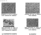
- FIG. 4 is a view illustrating a comparison between the film that has passed the film wrinkle removing roller according to the Example of the present invention and the film that has passed the film wrinkle improving roller according to the Comparative Example.
- FIG. 4(a) illustrates a photograph of the surface of the porous film and an SEM photograph of pores in the surface of the film that has been in contact with the film wrinkle improving roller of Comparative Example
- FIG. 4(b) illustrates a photograph of the surface of the porous film and an SEM photograph of pores in the surface of the film that has been in contact with the film wrinkle removing roller of Example of the present invention.
Landscapes
- Registering, Tensioning, Guiding Webs, And Rollers Therefor (AREA)
- Delivering By Means Of Belts And Rollers (AREA)
- Rolls And Other Rotary Bodies (AREA)
- Separation Using Semi-Permeable Membranes (AREA)
Abstract
Description
- The present invention relates to a film wrinkle removing roller, and more particularly, to a film wrinkle removing roller in which pattern rolls coated with rubber are positioned at both ends of a cylindrical roll made of Teflon, and a porous film comes into contact with the roll and the pattern rolls, such that the film may be prevented from wrinkling and a surface of the film may be prevented from being abraded due to friction between the film and surfaces of the rolls.
- A porous film is applied as a porous reinforcement base used for a separation membrane for a rechargeable battery and a reinforcement membrane for a fuel cell. Examples of the porous film used in this application field include polyethylene (PE), polypropylene (PP), polytetrafluoroethylene (PTFE), and polyethylene terephthalate (PET) films.
- Here, multiple rolls may be used to convey the film during the process of producing the porous film, and these rolls may be made of various materials in accordance with the intended use or characteristics.
- In general, the porous film may be produced through a roll-to-roll film moving process. In this case, the porous film may wrinkle because tension is applied in a movement direction of the film while the thin porous film moves.
- Therefore, a process of removing a wrinkle of the film is considered as an important factor among the processes of producing the film, and as a result, an industrial roll capable of improving a wrinkle of the film is being developed.
- In the case of a film wrinkle improving roller in the related art, a cylindrical roll having a predetermined pattern is provided, and a raw film passes over the cylindrical roll, such that a wrinkle formed on the film is improved.
- However, in the case of the film wrinkle improving roller in the related art, a pattern roll is made of rubber and metal, and the thin film passes the pattern roll, and as a result, there is a problem in that frictional force between the surface of the film and the rubber pattern roll is increased, which causes damage to the film.
- In addition, because the film wrinkle improving rubber roller in the related art has the single pattern roll made of rubber, there is a problem in that an afterimage of a pattern is formed on the surface of the film while the film passes the pattern roll. For this reason, there is a problem in that the surface of the film is not uniformly coated during the film coating.
- In addition, in the case of the film wrinkle improving roller in the related art, because the entire surface of the cylindrical roll is made of only rubber, there is a problem in that a film movement property deteriorates due to frictional force between the film and the roll. For this reason, there is a problem in that productivity of the film deteriorates.
- An object of the present invention is to provide a film wrinkle removing roller in which a pair of pattern rolls coated with rubber is provided at both ends of a cylindrical roll made of Teflon, and a thin porous film comes into contact with the roll and the pattern rolls, such that an abrasion, which causes an afterimage of a pattern to be formed on a surface of the film by a pattern shape, may be prevented and the surface of the film may be uniformly coated during film coating.
- In addition, an object according to an exemplary embodiment of the present invention is to provide a film wrinkle removing roller in which a cylindrical roll, which comes into contact with an effective width of a raw film, is made of Teflon having low frictional force, such that the film passing the roll is unwrinkled in a width direction by pattern rolls, made of rubber, at both ends of the roll while the film passes between the roll and the pattern rolls, and the film may smoothly move without wrinkles, and as a result, productivity of the film may be improved.
- The present invention provides a film wrinkle removing roller including: a roll having a cylindrical shape; a pair of pattern rolls positioned at both ends of the roll and having patterns; and a roll fixing unit configured to fix positions of the roll and the pattern rolls, in which the roll and the pattern rolls are separable from one another and made of materials having different frictional forces.
- In the exemplary embodiment, the roll may be made of metal and an entire surface of the roll may be coated with Teflon with a predetermined thickness.
- In the exemplary embodiment, the roll may be made of Teflon.
- In the exemplary embodiment, the pattern roll may be made of metal and an entire surface of the pattern roll may be coated with rubber with a predetermined thickness.
- In the exemplary embodiment, the pattern rolls may include first and second pattern rolls disposed at the both ends of the roll, respectively.
- In the exemplary embodiment, the patterns of the first and second pattern rolls may be formed to be symmetrical to one another.
- According to one aspect of the present invention, the pair of pattern rolls coated with rubber is provided at both ends of the cylindrical roll made of Teflon, and the thin porous film comes into contact with the roll and the pattern rolls, such that an abrasion, which causes an afterimage of a pattern to be formed on the surface of the film, may be prevented and the surface of the film may be uniformly coated during the film coating.
- In addition, the cylindrical roll is made of Teflon having low frictional force, such that the film passing the roll is unwrinkled in the width direction by the pattern rolls, made of rubber, at both ends of the roll while the film passes between the roll and the pattern rolls, and the film may smoothly move without wrinkles, and as a result, productivity of the film may be improved.
-
-
FIG. 1 is a view schematically illustrating a structure of a filmwrinkle removing roller 100 according to an exemplary embodiment of the present invention. -
FIG. 2 is a view schematically illustrating a state in which a film comes into contact with the filmwrinkle removing roller 100 according to the exemplary embodiment of the present invention. -
FIG. 3(a) is a view schematically illustrating a shape of a film wrinkle improving roller according to a Comparative Example, andFIG. 3(b) is a view schematically illustrating a shape of the film wrinkle removing roller according to the Example of the present invention. -
FIG. 4 is a view illustrating a comparison between the film that has passed the film wrinkle removing roller according to the Example of the present invention and the film that has passed the film wrinkle improving roller according to the Comparative Example. -
- 100:
- Film wrinkle removing roller
- 10:
- Roll
- 20:
- Pattern roll
- 20a:
- First pattern roll
- 20b:
- Second pattern roll
- 30:
- Roll fixing unit
- Hereinafter, the present invention will be described in detail with reference to the accompanying drawings. Here, repeated descriptions and detailed descriptions of publicly-known functions and configurations will be omitted so as to avoid unnecessarily obscuring the subject matter of the present invention. Exemplary embodiments of the present invention are provided to completely explain the present invention to a person with ordinary skill in the art. Therefore, shapes and sizes of elements illustrated in the drawings may be exaggerated for a more apparent description.
- Throughout the specification, unless explicitly described to the contrary, the word "comprise" or "include" and variations, such as "comprises", "comprising", "includes" or "including", means the further inclusion of stated constituent elements, not the exclusion of any other constituent elements.
- Hereinafter, exemplary embodiments are proposed to help understand the present invention. However, the following exemplary embodiments are provided just for more easily understanding the present invention, and the contents of the present invention are not limited by the exemplary embodiments.
-
FIG. 1 is a view schematically illustrating a structure of a filmwrinkle removing roller 100 according to an exemplary embodiment of the present invention, andFIG. 2 is a view schematically illustrating a state in which a film comes into contact with the filmwrinkle removing roller 100 according to the exemplary embodiment of the present invention. - Referring to
FIG. 1 , the filmwrinkle removing roller 100 according to the exemplary embodiment of the present invention may include acylindrical roll 10, a pair ofpattern rolls 20 having patterns, and aroll fixing unit 30 configured to fix positions of theroll 10 and thepattern rolls 20. - First, the
roll 10 has a cylindrical shape, and an entire surface of theroll 10 may be plain without patterns. - The
roll 10 may be made of metal such as aluminum, copper, or zinc and the entire surface of theroll 10 made of metal may be coated with Teflon (PTFE), or theentire roll 10 may be made of Teflon. - For example, the
cylindrical roll 10 is made of aluminum, the entire surface of thealuminum roll 10 is coated with Teflon with a predetermined thickness, and then the Teflon is hardened at a hardening temperature, such that surface frictional force of theroll 10 may be minimized. - In particular, the
cylindrical roll 10 may come into contact with a porous film (not illustrated). In this case, the porous film may be used for a separation membrane for a rechargeable battery and a reinforcement membrane of a fuel cell. As the porous film, polyethylene (PE), polypropylene (PP), polytetrafluoroethylene (PTFE), and polyethylene terephthalate (PET) may be applied. - When the
roll 10 made of Teflon and the porous film come into contact with each other, the frictional force between the porous film and theroll 10 is minimized, such that a raw porous film may easily move, and thus productivity of the porous film may be improved. - In this case, a length of the
roll 10 may be equal to a width (length) of an effective area of the porous film to be in contact with theroll 10, such that damage to the effective area of the surface of the porous film may be prevented and the film may be prevented from being torn. - In addition, the
roll 10 is coated with Teflon with a diameter equal to a diameter of the effective area of the porous film, such that a pore structure of the surface of the porous film may be prevented from being deformed when the porous film passes theroll 10. - Next, the pair of pattern rolls 20 may be positioned at both ends of the
cylindrical roll 10, and may include first and second pattern rolls 20a and 20b disposed at the both ends of theroll 10, respectively. - Here, the
cylindrical roll 10 and the pair of pattern rolls 20 may be separated from one another and may be made of materials having different frictional forces. - The pattern roll 20 may be made of metal such as aluminum, copper, or zinc, and the entire surface of the pattern roll 20 made of metal may be coated with rubber with a predetermined thickness.
- The rubber may be styrene-butadiene rubber (SBR), butadiene rubber (BR), chloroprene rubber (CR), nitrile rubber (NBR), ethylene-propylene rubber (EPDM), chlorosulfonated polyethylene rubber (CSM), acrylic rubber (ACM), fluororubber (FPM), or the like.
- For example, the first and second pattern rolls 20a and 20b each having a cylindrical shape may be made of aluminum, the entire surface of each of the first and second pattern rolls 20a and 20b may be coated with styrene-butadiene rubber with a predetermined thickness, and then pattern processing may be performed to form various patterns on the pattern rolls 20.
- The first and second pattern rolls 20a and 20b formed with the patterns are hardened at a hardening temperature of the rubber and then may be assembled to both ends of the
roll 10. - Here, the hardening temperature of the pattern rolls 20 and the hardening temperature of the
roll 10 are different from each other, and as a result, theroll 10 and the pattern rolls 20 are processed at the different hardening temperatures and then may be assembled and integrated. - The patterns of the first and second pattern rolls 20a and 20b may be formed to be symmetrical to one another, and the first and second pattern rolls 20a and 20b may have various patterns such as V-shaped patterns (chevrons), herringbone patterns, diamond patterns, horizontal patterns, vertical patterns, or diagonal patterns.
- For example, in the case in which the pattern rolls 20 have diagonal patterns, diagonal grooves and diagonal protrusions may be symmetrically formed on the first and second pattern rolls 20a and 20b, and the diagonal protrusions of the first and second pattern rolls 20a and 20b may be made of rubber to improve surface frictional force.
- Referring to
FIG. 2 , the first and second pattern rolls 20a and 20b formed with the patterns may be disposed at and assembled to both ends of thecylindrical roll 10, and the surfaces of theroll 10 and the first and second pattern rolls 20a and 20b, which are integrated, may come into contact with the porous film. - In more detail, the diameter of the
roll 10 made of Teflon may be equal to the diameter of the effective area of the porous film, the first and second pattern rolls 20a and 20b made of rubber may be assembled to and integrated with both ends of theroll 10, and the porous film may come into contact with theroll 10 and the pattern rolls 20 which are integrated. - In this case, a portion of the porous film, which comes into contact with the
roll 10 made of Teflon, is the effective area of the film where the abrasion of the film is prevented. Portions of the porous film, which come into contact with the first and second pattern rolls 20a and 20b, are both edges of the film except for the effective area and may be cut out by a rear end edge trimming (slitting) process. - In addition, the patterns of the first and second pattern rolls 20a and 20b are made of rubber, such that frictional force may be applied between the pattern rolls 20 and the porous film. Therefore, the first and second pattern rolls 20a and 20b pull the porous film in the width direction of the film, such that wrinkles formed in the movement direction of the film may be removed.
- Since the
cylindrical roll 10 made of Teflon is provided between the pair of pattern rolls 20 made of rubber and the thin porous film comes into contact with theroll 10 and the pattern rolls 20, it is possible to prevent an abrasion that causes an afterimage of the pattern to be formed on the surface of the porous film, it is possible to prevent an abrasion of a pore structure of the surface of the film, and as a result, it is possible to uniformly coat the surface of the film during the film coating. - In particular, the process of removing the wrinkle of the film and the process of preventing damage to the film are simultaneously performed while the porous film comes into contact with the
roll 10 and the pattern rolls 20, such that it is possible to shorten the time taken to move the porous film, and it is possible to improve efficiency in producing the porous film. - Next, the
roll fixing unit 30 may be inserted into the assembly of theroll 10 and the pattern rolls 20. In this case, theroll fixing unit 30 may be made of metal such as aluminum, copper, or zinc. - A length of the
roll fixing unit 30 may vary depending on the diameters of theroll 10 and the pattern rolls 20. The length of theroll fixing unit 30 may also be increased as the diameters of theroll 10 and the pattern rolls 20 are increased. - As described above, since the
roll fixing unit 30 is inserted into theroll 10 and the pattern rolls 20 to fix the positions of theroll 10 and the pattern rolls 20, it is possible to prevent theroll 10 and the pattern rolls 20 from being separated from one another during the process of moving the porous film. - A roll was manufactured by coating a cylindrical body made of aluminum with Teflon (PTFE). In addition, pattern rolls were manufactured by coating a pair of cylindrical bodies made of aluminum with styrene-butadiene rubber (SBR) and then forming diagonal patterns thereon. Here, the diagonal patterns of the pair of pattern rolls were formed to be symmetrical to one another. The pair of pattern rolls was disposed at both ends of the manufactured roll, the roll fixing unit was inserted into the roll and the pattern rolls, and then the roll and the pattern rolls were assembled and integrated, such that a film wrinkle removing roller was manufactured.
- An entire cylindrical body was made of styrene-butadiene rubber (SBR), and then V-shaped patterns were formed on the entire surface of the body, such that a film wrinkle improving roller was manufactured by using only the pattern rolls. Here, the V-shaped patterns of the pattern rolls were provided in the form of diagonal patterns symmetrical to one another.
- The porous films were brought into contact with the film wrinkle improving roller of Comparative Example and the film wrinkle removing roller of Example. In this case, the porous films in contact with the film wrinkle improving roller of Comparative Example and the film wrinkle removing roller of Example have the same material, the same shape, and the same size, and the porous films made of polypropylene (PP) were provided.
- In this case, the Comparative Example and the Example operate at the same temperature, and the magnitude of the movement tension of the porous film remains the same in the Comparative Example and the Example.
-
FIG. 3(a) is a view schematically illustrating a shape of a film wrinkle improving roller according to a Comparative Example, andFIG. 3(b) is a view schematically illustrating a shape of the film wrinkle removing roller according to the Example of the present invention. -
FIG. 4 is a view illustrating a comparison between the film that has passed the film wrinkle removing roller according to the Example of the present invention and the film that has passed the film wrinkle improving roller according to the Comparative Example. - Referring to
FIG. 4, FIG. 4(a) illustrates a photograph of the surface of the porous film and an SEM photograph of pores in the surface of the film that has been in contact with the film wrinkle improving roller of Comparative Example, andFIG. 4(b) illustrates a photograph of the surface of the porous film and an SEM photograph of pores in the surface of the film that has been in contact with the film wrinkle removing roller of Example of the present invention. - Afterimages identical to the V-shaped patterns of the pattern rolls made of rubber were formed on the surface of the porous film that had been in contact with the film wrinkle improving roller of Comparative Example, and an abrasion occurred on the surface of the film. For this reason, the pores were clogged as the pore structure of the surface of the film was deformed.
- In contrast, afterimages of the diagonal patterns of the pattern rolls made of rubber were rarely formed on the surface of the porous film that had been in contact with the film wrinkle removing roller of Example, and the pore structure of the surface of the porous film was maintained as it is without being deformed.
- That is, it can be seen that in comparison with the surface of the porous film that has been in contact with the film wrinkle improving roller of Comparative Example, less damage occurs on the surface of the porous film and an abrasion of the surface of the film is prevented, such that the deformation of the pores in the surface of the film is prevented, in the case of the porous film that has been in contact with the film wrinkle removing roller of Example.
- While the present invention has been described above with reference to the exemplary embodiments, it may be understood by those skilled in the art that the present invention may be variously modified and changed without departing from the spirit and scope of the present invention disclosed in the claims.
Claims (6)
- A film wrinkle removing roller comprising:a roll having a cylindrical shape;a pair of pattern rolls positioned at both ends of the roll and having patterns; anda roll fixing unit configured to fix positions of the roll and the pattern rolls,wherein the roll and the pattern rolls are separable from one another and made of materials having different frictional forces.
- The film wrinkle removing roller of claim 1, wherein the roll is made of metal and an entire surface of the roll is coated with Teflon with a predetermined thickness.
- The film wrinkle removing roller of claim 1, wherein the roll is made of Teflon.
- The film wrinkle removing roller of claim 1, wherein the pattern roll is made of metal and an entire surface of the pattern roll is coated with rubber with a predetermined thickness.
- The film wrinkle removing roller of claim 1, wherein the pattern rolls include first and second pattern rolls disposed at the both ends of the roll, respectively.
- The film wrinkle removing roller of claim 5, wherein the patterns of the first and second pattern rolls are formed to be symmetrical to one another.
Applications Claiming Priority (2)
| Application Number | Priority Date | Filing Date | Title |
|---|---|---|---|
| KR1020180056454A KR102616738B1 (en) | 2018-05-17 | 2018-05-17 | Roller for removing wrinkles of film |
| PCT/KR2019/005289 WO2019221427A1 (en) | 2018-05-17 | 2019-05-02 | Film wrinkle removing roller |
Publications (3)
| Publication Number | Publication Date |
|---|---|
| EP3778457A1 true EP3778457A1 (en) | 2021-02-17 |
| EP3778457A4 EP3778457A4 (en) | 2021-12-01 |
| EP3778457B1 EP3778457B1 (en) | 2024-04-17 |
Family
ID=68540463
Family Applications (1)
| Application Number | Title | Priority Date | Filing Date |
|---|---|---|---|
| EP19804123.8A Active EP3778457B1 (en) | 2018-05-17 | 2019-05-02 | Film wrinkle removing roller |
Country Status (6)
| Country | Link |
|---|---|
| US (1) | US11866279B2 (en) |
| EP (1) | EP3778457B1 (en) |
| JP (1) | JP7188673B2 (en) |
| KR (1) | KR102616738B1 (en) |
| CN (1) | CN112004765A (en) |
| WO (1) | WO2019221427A1 (en) |
Families Citing this family (4)
| Publication number | Priority date | Publication date | Assignee | Title |
|---|---|---|---|---|
| CN114919301A (en) * | 2022-06-07 | 2022-08-19 | 珠海恒盛条码设备有限公司 | Paper conveying mechanism and printing device |
| KR102548126B1 (en) * | 2022-11-09 | 2023-06-28 | (주)해원티앤디 | Apparatus and method for smoothing wrinkle of sheet material |
| KR20250136465A (en) * | 2024-03-08 | 2025-09-16 | 삼성에스디아이 주식회사 | Secondary battery manufacturing device, manufacturing method, and secondary battery therefrom |
| KR20250179490A (en) * | 2024-06-21 | 2025-12-30 | 삼성에스디아이 주식회사 | Lamination Tape Feeding System of Electrode Plate Substrate |
Family Cites Families (28)
| Publication number | Priority date | Publication date | Assignee | Title |
|---|---|---|---|---|
| JPS51141929A (en) * | 1975-05-30 | 1976-12-07 | Toyota Motor Corp | Carburetor for lamellar combustion rotary piston engine |
| JPS57111559A (en) | 1980-12-27 | 1982-07-12 | Ricoh Co Ltd | Exposing method of variable magnification type copier |
| JPS57111559U (en) * | 1980-12-27 | 1982-07-09 | ||
| US4566162A (en) * | 1982-10-26 | 1986-01-28 | American Roller Company | Stretcher/expander roller |
| JPH061510A (en) | 1992-04-23 | 1994-01-11 | Fuji Photo Film Co Ltd | Web transport roller and method of assembling the same |
| JPH05341684A (en) * | 1992-06-12 | 1993-12-24 | Seiko Epson Corp | Fuser |
| JP3743522B2 (en) | 1994-11-02 | 2006-02-08 | 富士写真フイルム株式会社 | Belt-shaped photosensitive material conveyance roller |
| FI105804B (en) | 1997-01-30 | 2000-10-13 | Valmet Corp | Removal roller, width stretch roller or equivalent for web material |
| JP2000086031A (en) | 1998-09-14 | 2000-03-28 | Toray Ind Inc | Sheet conveying device and sheet manufacturing method |
| JP2001317538A (en) * | 2000-05-11 | 2001-11-16 | Arai Pump Mfg Co Ltd | Elastic roller and fixing device |
| JP2002086207A (en) | 2000-09-14 | 2002-03-26 | Kawasaki Steel Corp | Roll to prevent wrinkling of metal foil strip |
| JP4149737B2 (en) | 2002-05-28 | 2008-09-17 | 株式会社沖データ | Belt unit and image forming apparatus |
| KR20050023340A (en) | 2002-06-27 | 2005-03-09 | 크라이오백 인코포레이티드 | Wrinkle reduction assembly |
| WO2005040018A1 (en) * | 2003-10-28 | 2005-05-06 | Toray Industries, Inc. | Web smoothing roller, and web roll producing device and method |
| JP2005344750A (en) | 2004-05-31 | 2005-12-15 | Kyocera Mita Corp | Belt drive mechanism and electronic photographing device using the same |
| JP4348638B2 (en) | 2006-03-08 | 2009-10-21 | 村田機械株式会社 | Roller member and image forming apparatus |
| JP4656344B2 (en) * | 2008-08-27 | 2011-03-23 | 富士フイルム株式会社 | Web conveying method and apparatus |
| KR101066219B1 (en) * | 2009-01-06 | 2011-09-21 | 유용승 | Industrial rollers |
| JP5385178B2 (en) | 2010-02-26 | 2014-01-08 | 富士フイルム株式会社 | Flexible film transport apparatus and barrier film manufacturing method |
| JP5649853B2 (en) | 2010-05-26 | 2015-01-07 | 株式会社ヒラノテクシード | Guide roll |
| JP5434859B2 (en) * | 2010-09-17 | 2014-03-05 | 住友金属鉱山株式会社 | Method and apparatus for stretching wrinkles on can roll |
| JP2013167730A (en) * | 2012-02-15 | 2013-08-29 | Brother Ind Ltd | Fixing roller and manufacturing method of the same |
| JP5688858B2 (en) * | 2013-03-28 | 2015-03-25 | 富士フイルム株式会社 | Functional film manufacturing method and web transport device |
| JP6070455B2 (en) | 2013-07-19 | 2017-02-01 | 住友金属鉱山株式会社 | Wrinkle stretching roll, wrinkle stretching method, surface treatment apparatus and surface treatment method |
| CN204849352U (en) * | 2015-06-08 | 2015-12-09 | 崔小彦 | What medical gauze stretched cloth machine prevents fold device |
| KR20180024150A (en) * | 2016-08-29 | 2018-03-08 | 주식회사동서산업롤 | Go straight and use the friction roll for improvement of lines |
| JP2018145010A (en) | 2017-03-03 | 2018-09-20 | 住友化学株式会社 | Conveying apparatus and film manufacturing method |
| CN206901436U (en) * | 2017-06-15 | 2018-01-19 | 世源科技(芜湖)新材料有限公司 | A kind of Crease-resistant device |
-
2018
- 2018-05-17 KR KR1020180056454A patent/KR102616738B1/en active Active
-
2019
- 2019-05-02 US US17/055,675 patent/US11866279B2/en active Active
- 2019-05-02 WO PCT/KR2019/005289 patent/WO2019221427A1/en not_active Ceased
- 2019-05-02 EP EP19804123.8A patent/EP3778457B1/en active Active
- 2019-05-02 CN CN201980027311.8A patent/CN112004765A/en active Pending
- 2019-05-02 JP JP2020556945A patent/JP7188673B2/en active Active
Also Published As
| Publication number | Publication date |
|---|---|
| US11866279B2 (en) | 2024-01-09 |
| US20210198071A1 (en) | 2021-07-01 |
| JP2021517881A (en) | 2021-07-29 |
| EP3778457B1 (en) | 2024-04-17 |
| KR102616738B1 (en) | 2023-12-21 |
| EP3778457A4 (en) | 2021-12-01 |
| KR20190131717A (en) | 2019-11-27 |
| JP7188673B2 (en) | 2022-12-13 |
| CN112004765A (en) | 2020-11-27 |
| WO2019221427A1 (en) | 2019-11-21 |
Similar Documents
| Publication | Publication Date | Title |
|---|---|---|
| EP3778457B1 (en) | Film wrinkle removing roller | |
| JP6698904B2 (en) | Device and method for fixing a polymer to a substrate | |
| JP2005514515A (en) | Microstructured release liner | |
| KR101913476B1 (en) | Battery separator producing method and battery separator producing apparatus | |
| JP2008266026A (en) | Web guide roller and web guide method | |
| JP7067426B2 (en) | Electrode manufacturing method | |
| JP5853943B2 (en) | Battery electrode manufacturing apparatus and electrode manufacturing method | |
| EP3015184A1 (en) | Molded material manufacturing method and molded material | |
| JP2018032604A (en) | Electrode manufacturing apparatus | |
| JP5387623B2 (en) | Coating roller manufacturing method and coating roller | |
| JP2013098095A (en) | Coating device and manufacturing method of electrode | |
| JPH08134645A (en) | Vacuum processing equipment for plastic film | |
| US20140361109A1 (en) | Multilayered film roll with reduced defects | |
| KR20180024150A (en) | Go straight and use the friction roll for improvement of lines | |
| JP2005230968A (en) | Grooved roller and slitter | |
| JP4210159B2 (en) | Film transport roll and film transport apparatus | |
| US10317835B2 (en) | Peeling member and peeling device | |
| JP6158370B2 (en) | Film winding body and manufacturing method thereof | |
| EP3659951B1 (en) | Elastic roller, nip roller, and conveying device | |
| KR101230844B1 (en) | Manufacturing method of porous polytetrafluoroethylene film based on batch-type drawn using guide roller and polytetrafluoroethylene film having uniform thickness manufactured thereby | |
| JP2015117409A (en) | Electrodeposition drum | |
| JP4207924B2 (en) | Cellulose triacetate film production equipment | |
| JP2005178996A (en) | Guide roll and magnetic tape manufacturing equipment | |
| JP2024046246A (en) | Manufacturing method of the electrode body | |
| JPH04175150A (en) | Manufacture of fiber reinforced plastic roll |
Legal Events
| Date | Code | Title | Description |
|---|---|---|---|
| STAA | Information on the status of an ep patent application or granted ep patent |
Free format text: STATUS: THE INTERNATIONAL PUBLICATION HAS BEEN MADE |
|
| PUAI | Public reference made under article 153(3) epc to a published international application that has entered the european phase |
Free format text: ORIGINAL CODE: 0009012 |
|
| STAA | Information on the status of an ep patent application or granted ep patent |
Free format text: STATUS: REQUEST FOR EXAMINATION WAS MADE |
|
| 17P | Request for examination filed |
Effective date: 20201027 |
|
| AK | Designated contracting states |
Kind code of ref document: A1 Designated state(s): AL AT BE BG CH CY CZ DE DK EE ES FI FR GB GR HR HU IE IS IT LI LT LU LV MC MK MT NL NO PL PT RO RS SE SI SK SM TR |
|
| AX | Request for extension of the european patent |
Extension state: BA ME |
|
| DAV | Request for validation of the european patent (deleted) | ||
| DAX | Request for extension of the european patent (deleted) | ||
| A4 | Supplementary search report drawn up and despatched |
Effective date: 20211029 |
|
| RIC1 | Information provided on ipc code assigned before grant |
Ipc: B65H 27/00 20060101ALI20211025BHEP Ipc: B65H 23/025 20060101AFI20211025BHEP |
|
| GRAP | Despatch of communication of intention to grant a patent |
Free format text: ORIGINAL CODE: EPIDOSNIGR1 |
|
| STAA | Information on the status of an ep patent application or granted ep patent |
Free format text: STATUS: GRANT OF PATENT IS INTENDED |
|
| INTG | Intention to grant announced |
Effective date: 20240206 |
|
| GRAS | Grant fee paid |
Free format text: ORIGINAL CODE: EPIDOSNIGR3 |
|
| GRAA | (expected) grant |
Free format text: ORIGINAL CODE: 0009210 |
|
| STAA | Information on the status of an ep patent application or granted ep patent |
Free format text: STATUS: THE PATENT HAS BEEN GRANTED |
|
| AK | Designated contracting states |
Kind code of ref document: B1 Designated state(s): AL AT BE BG CH CY CZ DE DK EE ES FI FR GB GR HR HU IE IS IT LI LT LU LV MC MK MT NL NO PL PT RO RS SE SI SK SM TR |
|
| REG | Reference to a national code |
Ref country code: GB Ref legal event code: FG4D |
|
| REG | Reference to a national code |
Ref country code: CH Ref legal event code: EP |
|
| REG | Reference to a national code |
Ref country code: DE Ref legal event code: R096 Ref document number: 602019050532 Country of ref document: DE |
|
| REG | Reference to a national code |
Ref country code: IE Ref legal event code: FG4D |
|
| REG | Reference to a national code |
Ref country code: LT Ref legal event code: MG9D |
|
| REG | Reference to a national code |
Ref country code: NL Ref legal event code: MP Effective date: 20240417 |
|
| REG | Reference to a national code |
Ref country code: AT Ref legal event code: MK05 Ref document number: 1677090 Country of ref document: AT Kind code of ref document: T Effective date: 20240417 |
|
| PG25 | Lapsed in a contracting state [announced via postgrant information from national office to epo] |
Ref country code: NL Free format text: LAPSE BECAUSE OF FAILURE TO SUBMIT A TRANSLATION OF THE DESCRIPTION OR TO PAY THE FEE WITHIN THE PRESCRIBED TIME-LIMIT Effective date: 20240417 |
|
| PG25 | Lapsed in a contracting state [announced via postgrant information from national office to epo] |
Ref country code: NL Free format text: LAPSE BECAUSE OF FAILURE TO SUBMIT A TRANSLATION OF THE DESCRIPTION OR TO PAY THE FEE WITHIN THE PRESCRIBED TIME-LIMIT Effective date: 20240417 |
|
| PG25 | Lapsed in a contracting state [announced via postgrant information from national office to epo] |
Ref country code: IS Free format text: LAPSE BECAUSE OF FAILURE TO SUBMIT A TRANSLATION OF THE DESCRIPTION OR TO PAY THE FEE WITHIN THE PRESCRIBED TIME-LIMIT Effective date: 20240817 |
|
| PG25 | Lapsed in a contracting state [announced via postgrant information from national office to epo] |
Ref country code: BG Free format text: LAPSE BECAUSE OF FAILURE TO SUBMIT A TRANSLATION OF THE DESCRIPTION OR TO PAY THE FEE WITHIN THE PRESCRIBED TIME-LIMIT Effective date: 20240417 |
|
| PG25 | Lapsed in a contracting state [announced via postgrant information from national office to epo] |
Ref country code: HR Free format text: LAPSE BECAUSE OF FAILURE TO SUBMIT A TRANSLATION OF THE DESCRIPTION OR TO PAY THE FEE WITHIN THE PRESCRIBED TIME-LIMIT Effective date: 20240417 Ref country code: FI Free format text: LAPSE BECAUSE OF FAILURE TO SUBMIT A TRANSLATION OF THE DESCRIPTION OR TO PAY THE FEE WITHIN THE PRESCRIBED TIME-LIMIT Effective date: 20240417 |
|
| PG25 | Lapsed in a contracting state [announced via postgrant information from national office to epo] |
Ref country code: GR Free format text: LAPSE BECAUSE OF FAILURE TO SUBMIT A TRANSLATION OF THE DESCRIPTION OR TO PAY THE FEE WITHIN THE PRESCRIBED TIME-LIMIT Effective date: 20240718 |
|
| PG25 | Lapsed in a contracting state [announced via postgrant information from national office to epo] |
Ref country code: PT Free format text: LAPSE BECAUSE OF FAILURE TO SUBMIT A TRANSLATION OF THE DESCRIPTION OR TO PAY THE FEE WITHIN THE PRESCRIBED TIME-LIMIT Effective date: 20240819 |
|
| PG25 | Lapsed in a contracting state [announced via postgrant information from national office to epo] |
Ref country code: ES Free format text: LAPSE BECAUSE OF FAILURE TO SUBMIT A TRANSLATION OF THE DESCRIPTION OR TO PAY THE FEE WITHIN THE PRESCRIBED TIME-LIMIT Effective date: 20240417 |
|
| PG25 | Lapsed in a contracting state [announced via postgrant information from national office to epo] |
Ref country code: AT Free format text: LAPSE BECAUSE OF FAILURE TO SUBMIT A TRANSLATION OF THE DESCRIPTION OR TO PAY THE FEE WITHIN THE PRESCRIBED TIME-LIMIT Effective date: 20240417 |
|
| PG25 | Lapsed in a contracting state [announced via postgrant information from national office to epo] |
Ref country code: PL Free format text: LAPSE BECAUSE OF FAILURE TO SUBMIT A TRANSLATION OF THE DESCRIPTION OR TO PAY THE FEE WITHIN THE PRESCRIBED TIME-LIMIT Effective date: 20240417 |
|
| PG25 | Lapsed in a contracting state [announced via postgrant information from national office to epo] |
Ref country code: LV Free format text: LAPSE BECAUSE OF FAILURE TO SUBMIT A TRANSLATION OF THE DESCRIPTION OR TO PAY THE FEE WITHIN THE PRESCRIBED TIME-LIMIT Effective date: 20240417 |
|
| PG25 | Lapsed in a contracting state [announced via postgrant information from national office to epo] |
Ref country code: PT Free format text: LAPSE BECAUSE OF FAILURE TO SUBMIT A TRANSLATION OF THE DESCRIPTION OR TO PAY THE FEE WITHIN THE PRESCRIBED TIME-LIMIT Effective date: 20240819 Ref country code: PL Free format text: LAPSE BECAUSE OF FAILURE TO SUBMIT A TRANSLATION OF THE DESCRIPTION OR TO PAY THE FEE WITHIN THE PRESCRIBED TIME-LIMIT Effective date: 20240417 Ref country code: NO Free format text: LAPSE BECAUSE OF FAILURE TO SUBMIT A TRANSLATION OF THE DESCRIPTION OR TO PAY THE FEE WITHIN THE PRESCRIBED TIME-LIMIT Effective date: 20240717 Ref country code: LV Free format text: LAPSE BECAUSE OF FAILURE TO SUBMIT A TRANSLATION OF THE DESCRIPTION OR TO PAY THE FEE WITHIN THE PRESCRIBED TIME-LIMIT Effective date: 20240417 Ref country code: IS Free format text: LAPSE BECAUSE OF FAILURE TO SUBMIT A TRANSLATION OF THE DESCRIPTION OR TO PAY THE FEE WITHIN THE PRESCRIBED TIME-LIMIT Effective date: 20240817 Ref country code: HR Free format text: LAPSE BECAUSE OF FAILURE TO SUBMIT A TRANSLATION OF THE DESCRIPTION OR TO PAY THE FEE WITHIN THE PRESCRIBED TIME-LIMIT Effective date: 20240417 Ref country code: GR Free format text: LAPSE BECAUSE OF FAILURE TO SUBMIT A TRANSLATION OF THE DESCRIPTION OR TO PAY THE FEE WITHIN THE PRESCRIBED TIME-LIMIT Effective date: 20240718 Ref country code: FI Free format text: LAPSE BECAUSE OF FAILURE TO SUBMIT A TRANSLATION OF THE DESCRIPTION OR TO PAY THE FEE WITHIN THE PRESCRIBED TIME-LIMIT Effective date: 20240417 Ref country code: ES Free format text: LAPSE BECAUSE OF FAILURE TO SUBMIT A TRANSLATION OF THE DESCRIPTION OR TO PAY THE FEE WITHIN THE PRESCRIBED TIME-LIMIT Effective date: 20240417 Ref country code: BG Free format text: LAPSE BECAUSE OF FAILURE TO SUBMIT A TRANSLATION OF THE DESCRIPTION OR TO PAY THE FEE WITHIN THE PRESCRIBED TIME-LIMIT Effective date: 20240417 Ref country code: AT Free format text: LAPSE BECAUSE OF FAILURE TO SUBMIT A TRANSLATION OF THE DESCRIPTION OR TO PAY THE FEE WITHIN THE PRESCRIBED TIME-LIMIT Effective date: 20240417 Ref country code: RS Free format text: LAPSE BECAUSE OF FAILURE TO SUBMIT A TRANSLATION OF THE DESCRIPTION OR TO PAY THE FEE WITHIN THE PRESCRIBED TIME-LIMIT Effective date: 20240717 |
|
| REG | Reference to a national code |
Ref country code: CH Ref legal event code: PL |
|
| PG25 | Lapsed in a contracting state [announced via postgrant information from national office to epo] |
Ref country code: DK Free format text: LAPSE BECAUSE OF FAILURE TO SUBMIT A TRANSLATION OF THE DESCRIPTION OR TO PAY THE FEE WITHIN THE PRESCRIBED TIME-LIMIT Effective date: 20240417 |
|
| PG25 | Lapsed in a contracting state [announced via postgrant information from national office to epo] |
Ref country code: LU Free format text: LAPSE BECAUSE OF NON-PAYMENT OF DUE FEES Effective date: 20240502 |
|
| REG | Reference to a national code |
Ref country code: DE Ref legal event code: R097 Ref document number: 602019050532 Country of ref document: DE |
|
| PG25 | Lapsed in a contracting state [announced via postgrant information from national office to epo] |
Ref country code: EE Free format text: LAPSE BECAUSE OF FAILURE TO SUBMIT A TRANSLATION OF THE DESCRIPTION OR TO PAY THE FEE WITHIN THE PRESCRIBED TIME-LIMIT Effective date: 20240417 |
|
| PG25 | Lapsed in a contracting state [announced via postgrant information from national office to epo] |
Ref country code: CZ Free format text: LAPSE BECAUSE OF FAILURE TO SUBMIT A TRANSLATION OF THE DESCRIPTION OR TO PAY THE FEE WITHIN THE PRESCRIBED TIME-LIMIT Effective date: 20240417 |
|
| PG25 | Lapsed in a contracting state [announced via postgrant information from national office to epo] |
Ref country code: SK Free format text: LAPSE BECAUSE OF FAILURE TO SUBMIT A TRANSLATION OF THE DESCRIPTION OR TO PAY THE FEE WITHIN THE PRESCRIBED TIME-LIMIT Effective date: 20240417 Ref country code: RO Free format text: LAPSE BECAUSE OF FAILURE TO SUBMIT A TRANSLATION OF THE DESCRIPTION OR TO PAY THE FEE WITHIN THE PRESCRIBED TIME-LIMIT Effective date: 20240417 |
|
| PG25 | Lapsed in a contracting state [announced via postgrant information from national office to epo] |
Ref country code: SM Free format text: LAPSE BECAUSE OF FAILURE TO SUBMIT A TRANSLATION OF THE DESCRIPTION OR TO PAY THE FEE WITHIN THE PRESCRIBED TIME-LIMIT Effective date: 20240417 |
|
| PG25 | Lapsed in a contracting state [announced via postgrant information from national office to epo] |
Ref country code: SM Free format text: LAPSE BECAUSE OF FAILURE TO SUBMIT A TRANSLATION OF THE DESCRIPTION OR TO PAY THE FEE WITHIN THE PRESCRIBED TIME-LIMIT Effective date: 20240417 Ref country code: SK Free format text: LAPSE BECAUSE OF FAILURE TO SUBMIT A TRANSLATION OF THE DESCRIPTION OR TO PAY THE FEE WITHIN THE PRESCRIBED TIME-LIMIT Effective date: 20240417 Ref country code: RO Free format text: LAPSE BECAUSE OF FAILURE TO SUBMIT A TRANSLATION OF THE DESCRIPTION OR TO PAY THE FEE WITHIN THE PRESCRIBED TIME-LIMIT Effective date: 20240417 Ref country code: LU Free format text: LAPSE BECAUSE OF NON-PAYMENT OF DUE FEES Effective date: 20240502 Ref country code: EE Free format text: LAPSE BECAUSE OF FAILURE TO SUBMIT A TRANSLATION OF THE DESCRIPTION OR TO PAY THE FEE WITHIN THE PRESCRIBED TIME-LIMIT Effective date: 20240417 Ref country code: DK Free format text: LAPSE BECAUSE OF FAILURE TO SUBMIT A TRANSLATION OF THE DESCRIPTION OR TO PAY THE FEE WITHIN THE PRESCRIBED TIME-LIMIT Effective date: 20240417 Ref country code: CZ Free format text: LAPSE BECAUSE OF FAILURE TO SUBMIT A TRANSLATION OF THE DESCRIPTION OR TO PAY THE FEE WITHIN THE PRESCRIBED TIME-LIMIT Effective date: 20240417 Ref country code: MC Free format text: LAPSE BECAUSE OF FAILURE TO SUBMIT A TRANSLATION OF THE DESCRIPTION OR TO PAY THE FEE WITHIN THE PRESCRIBED TIME-LIMIT Effective date: 20240417 Ref country code: CH Free format text: LAPSE BECAUSE OF NON-PAYMENT OF DUE FEES Effective date: 20240531 |
|
| PG25 | Lapsed in a contracting state [announced via postgrant information from national office to epo] |
Ref country code: IT Free format text: LAPSE BECAUSE OF FAILURE TO SUBMIT A TRANSLATION OF THE DESCRIPTION OR TO PAY THE FEE WITHIN THE PRESCRIBED TIME-LIMIT Effective date: 20240417 |
|
| PLBE | No opposition filed within time limit |
Free format text: ORIGINAL CODE: 0009261 |
|
| REG | Reference to a national code |
Ref country code: BE Ref legal event code: MM Effective date: 20240531 |
|
| STAA | Information on the status of an ep patent application or granted ep patent |
Free format text: STATUS: NO OPPOSITION FILED WITHIN TIME LIMIT |
|
| 26N | No opposition filed |
Effective date: 20250120 |
|
| PG25 | Lapsed in a contracting state [announced via postgrant information from national office to epo] |
Ref country code: IE Free format text: LAPSE BECAUSE OF NON-PAYMENT OF DUE FEES Effective date: 20240502 |
|
| PG25 | Lapsed in a contracting state [announced via postgrant information from national office to epo] |
Ref country code: SI Free format text: LAPSE BECAUSE OF FAILURE TO SUBMIT A TRANSLATION OF THE DESCRIPTION OR TO PAY THE FEE WITHIN THE PRESCRIBED TIME-LIMIT Effective date: 20240417 Ref country code: BE Free format text: LAPSE BECAUSE OF NON-PAYMENT OF DUE FEES Effective date: 20240531 |
|
| PGFP | Annual fee paid to national office [announced via postgrant information from national office to epo] |
Ref country code: DE Payment date: 20250422 Year of fee payment: 7 |
|
| PGFP | Annual fee paid to national office [announced via postgrant information from national office to epo] |
Ref country code: FR Payment date: 20250422 Year of fee payment: 7 |
|
| PG25 | Lapsed in a contracting state [announced via postgrant information from national office to epo] |
Ref country code: CY Free format text: LAPSE BECAUSE OF FAILURE TO SUBMIT A TRANSLATION OF THE DESCRIPTION OR TO PAY THE FEE WITHIN THE PRESCRIBED TIME-LIMIT; INVALID AB INITIO Effective date: 20190502 |
|
| PG25 | Lapsed in a contracting state [announced via postgrant information from national office to epo] |
Ref country code: HU Free format text: LAPSE BECAUSE OF FAILURE TO SUBMIT A TRANSLATION OF THE DESCRIPTION OR TO PAY THE FEE WITHIN THE PRESCRIBED TIME-LIMIT; INVALID AB INITIO Effective date: 20190502 |
|
| PG25 | Lapsed in a contracting state [announced via postgrant information from national office to epo] |
Ref country code: SE Free format text: LAPSE BECAUSE OF FAILURE TO SUBMIT A TRANSLATION OF THE DESCRIPTION OR TO PAY THE FEE WITHIN THE PRESCRIBED TIME-LIMIT Effective date: 20240417 |
|
| PGFP | Annual fee paid to national office [announced via postgrant information from national office to epo] |
Ref country code: GB Payment date: 20260324 Year of fee payment: 8 |