EP3777946B1 - Luer-lock-system für digitale ballonkatheter - Google Patents
Luer-lock-system für digitale ballonkatheter Download PDFInfo
- Publication number
- EP3777946B1 EP3777946B1 EP19191879.6A EP19191879A EP3777946B1 EP 3777946 B1 EP3777946 B1 EP 3777946B1 EP 19191879 A EP19191879 A EP 19191879A EP 3777946 B1 EP3777946 B1 EP 3777946B1
- Authority
- EP
- European Patent Office
- Prior art keywords
- catheter
- connector
- circuit board
- printed circuit
- catheter shaft
- Prior art date
- Legal status (The legal status is an assumption and is not a legal conclusion. Google has not performed a legal analysis and makes no representation as to the accuracy of the status listed.)
- Active
Links
- 239000004020 conductor Substances 0.000 claims description 99
- 239000000463 material Substances 0.000 claims description 22
- 238000000034 method Methods 0.000 claims description 11
- 238000002347 injection Methods 0.000 claims description 5
- 239000007924 injection Substances 0.000 claims description 5
- 229920001169 thermoplastic Polymers 0.000 claims description 5
- 239000004416 thermosoftening plastic Substances 0.000 claims description 5
- 238000004519 manufacturing process Methods 0.000 claims description 4
- 229920001721 polyimide Polymers 0.000 claims description 4
- 239000004642 Polyimide Substances 0.000 claims description 3
- 239000000976 ink Substances 0.000 description 8
- -1 Polybutylene terephthalate Polymers 0.000 description 7
- 239000012530 fluid Substances 0.000 description 7
- 238000011010 flushing procedure Methods 0.000 description 6
- 239000004417 polycarbonate Substances 0.000 description 6
- PPBRXRYQALVLMV-UHFFFAOYSA-N Styrene Chemical compound C=CC1=CC=CC=C1 PPBRXRYQALVLMV-UHFFFAOYSA-N 0.000 description 5
- 238000001746 injection moulding Methods 0.000 description 5
- 239000004697 Polyetherimide Substances 0.000 description 4
- 239000004793 Polystyrene Substances 0.000 description 4
- 229920001971 elastomer Polymers 0.000 description 4
- 239000000806 elastomer Substances 0.000 description 4
- 238000002513 implantation Methods 0.000 description 4
- 229920000515 polycarbonate Polymers 0.000 description 4
- 229920000728 polyester Polymers 0.000 description 4
- 229920001601 polyetherimide Polymers 0.000 description 4
- 238000005476 soldering Methods 0.000 description 4
- 229920001577 copolymer Polymers 0.000 description 3
- 239000000203 mixture Substances 0.000 description 3
- NLHHRLWOUZZQLW-UHFFFAOYSA-N Acrylonitrile Chemical compound C=CC#N NLHHRLWOUZZQLW-UHFFFAOYSA-N 0.000 description 2
- 229920008347 Cellulose acetate propionate Polymers 0.000 description 2
- 229920001634 Copolyester Polymers 0.000 description 2
- 229920000089 Cyclic olefin copolymer Polymers 0.000 description 2
- 239000004713 Cyclic olefin copolymer Substances 0.000 description 2
- 229930040373 Paraformaldehyde Natural products 0.000 description 2
- 229920000954 Polyglycolide Polymers 0.000 description 2
- 239000004721 Polyphenylene oxide Substances 0.000 description 2
- 239000004743 Polypropylene Substances 0.000 description 2
- 239000004433 Thermoplastic polyurethane Substances 0.000 description 2
- 238000002399 angioplasty Methods 0.000 description 2
- 229920001903 high density polyethylene Polymers 0.000 description 2
- 239000004700 high-density polyethylene Substances 0.000 description 2
- 229920000092 linear low density polyethylene Polymers 0.000 description 2
- 239000004707 linear low-density polyethylene Substances 0.000 description 2
- 229920001179 medium density polyethylene Polymers 0.000 description 2
- 239000004701 medium-density polyethylene Substances 0.000 description 2
- 229920000747 poly(lactic acid) Polymers 0.000 description 2
- 229920003229 poly(methyl methacrylate) Polymers 0.000 description 2
- 229920002492 poly(sulfone) Polymers 0.000 description 2
- 229920001707 polybutylene terephthalate Polymers 0.000 description 2
- 229920000139 polyethylene terephthalate Polymers 0.000 description 2
- 239000005020 polyethylene terephthalate Substances 0.000 description 2
- 239000004633 polyglycolic acid Substances 0.000 description 2
- 239000004626 polylactic acid Substances 0.000 description 2
- 239000004926 polymethyl methacrylate Substances 0.000 description 2
- 229920000306 polymethylpentene Polymers 0.000 description 2
- 239000011116 polymethylpentene Substances 0.000 description 2
- 229920006324 polyoxymethylene Polymers 0.000 description 2
- 229920001955 polyphenylene ether Polymers 0.000 description 2
- 229920002223 polystyrene Polymers 0.000 description 2
- 229920002981 polyvinylidene fluoride Polymers 0.000 description 2
- 238000007493 shaping process Methods 0.000 description 2
- 229920003048 styrene butadiene rubber Polymers 0.000 description 2
- 229920002803 thermoplastic polyurethane Polymers 0.000 description 2
- 229920006342 thermoplastic vulcanizate Polymers 0.000 description 2
- FDSYTWVNUJTPMA-UHFFFAOYSA-N 2-[3,9-bis(carboxymethyl)-3,6,9,15-tetrazabicyclo[9.3.1]pentadeca-1(15),11,13-trien-6-yl]acetic acid Chemical compound C1N(CC(O)=O)CCN(CC(=O)O)CCN(CC(O)=O)CC2=CC=CC1=N2 FDSYTWVNUJTPMA-UHFFFAOYSA-N 0.000 description 1
- FPWNLURCHDRMHC-UHFFFAOYSA-N 4-chlorobiphenyl Chemical compound C1=CC(Cl)=CC=C1C1=CC=CC=C1 FPWNLURCHDRMHC-UHFFFAOYSA-N 0.000 description 1
- VEXZGXHMUGYJMC-UHFFFAOYSA-M Chloride anion Chemical compound [Cl-] VEXZGXHMUGYJMC-UHFFFAOYSA-M 0.000 description 1
- VVQNEPGJFQJSBK-UHFFFAOYSA-N Methyl methacrylate Chemical compound COC(=O)C(C)=C VVQNEPGJFQJSBK-UHFFFAOYSA-N 0.000 description 1
- 239000002033 PVDF binder Substances 0.000 description 1
- 208000031481 Pathologic Constriction Diseases 0.000 description 1
- 239000004952 Polyamide Substances 0.000 description 1
- 229920002614 Polyether block amide Polymers 0.000 description 1
- 229920000265 Polyparaphenylene Polymers 0.000 description 1
- MTAZNLWOLGHBHU-UHFFFAOYSA-N butadiene-styrene rubber Chemical compound C=CC=C.C=CC1=CC=CC=C1 MTAZNLWOLGHBHU-UHFFFAOYSA-N 0.000 description 1
- HKQOBOMRSSHSTC-UHFFFAOYSA-N cellulose acetate Chemical compound OC1C(O)C(O)C(CO)OC1OC1C(CO)OC(O)C(O)C1O.CC(=O)OCC1OC(OC(C)=O)C(OC(C)=O)C(OC(C)=O)C1OC1C(OC(C)=O)C(OC(C)=O)C(OC(C)=O)C(COC(C)=O)O1.CCC(=O)OCC1OC(OC(=O)CC)C(OC(=O)CC)C(OC(=O)CC)C1OC1C(OC(=O)CC)C(OC(=O)CC)C(OC(=O)CC)C(COC(=O)CC)O1 HKQOBOMRSSHSTC-UHFFFAOYSA-N 0.000 description 1
- 230000001419 dependent effect Effects 0.000 description 1
- 150000002148 esters Chemical class 0.000 description 1
- BXOUVIIITJXIKB-UHFFFAOYSA-N ethene;styrene Chemical group C=C.C=CC1=CC=CC=C1 BXOUVIIITJXIKB-UHFFFAOYSA-N 0.000 description 1
- RTZKZFJDLAIYFH-UHFFFAOYSA-N ether Substances CCOCC RTZKZFJDLAIYFH-UHFFFAOYSA-N 0.000 description 1
- LYCAIKOWRPUZTN-UHFFFAOYSA-N ethylene glycol Natural products OCCO LYCAIKOWRPUZTN-UHFFFAOYSA-N 0.000 description 1
- WGCNASOHLSPBMP-UHFFFAOYSA-N hydroxyacetaldehyde Natural products OCC=O WGCNASOHLSPBMP-UHFFFAOYSA-N 0.000 description 1
- 238000009413 insulation Methods 0.000 description 1
- QQVIHTHCMHWDBS-UHFFFAOYSA-L isophthalate(2-) Chemical compound [O-]C(=O)C1=CC=CC(C([O-])=O)=C1 QQVIHTHCMHWDBS-UHFFFAOYSA-L 0.000 description 1
- 239000004973 liquid crystal related substance Substances 0.000 description 1
- 229940127554 medical product Drugs 0.000 description 1
- VPRUMANMDWQMNF-UHFFFAOYSA-N phenylethane boronic acid Chemical compound OB(O)CCC1=CC=CC=C1 VPRUMANMDWQMNF-UHFFFAOYSA-N 0.000 description 1
- 229920003023 plastic Polymers 0.000 description 1
- 239000004033 plastic Substances 0.000 description 1
- 229920002647 polyamide Polymers 0.000 description 1
- 229920001123 polycyclohexylenedimethylene terephthalate Polymers 0.000 description 1
- 229920000570 polyether Polymers 0.000 description 1
- 229920013636 polyphenyl ether polymer Polymers 0.000 description 1
- 229920001155 polypropylene Polymers 0.000 description 1
- 229920001343 polytetrafluoroethylene Polymers 0.000 description 1
- 239000004810 polytetrafluoroethylene Substances 0.000 description 1
- 239000004800 polyvinyl chloride Substances 0.000 description 1
- 229920000915 polyvinyl chloride Polymers 0.000 description 1
- SCUZVMOVTVSBLE-UHFFFAOYSA-N prop-2-enenitrile;styrene Chemical compound C=CC#N.C=CC1=CC=CC=C1 SCUZVMOVTVSBLE-UHFFFAOYSA-N 0.000 description 1
- 230000003014 reinforcing effect Effects 0.000 description 1
- 208000037804 stenosis Diseases 0.000 description 1
- 230000036262 stenosis Effects 0.000 description 1
- 229920006132 styrene block copolymer Polymers 0.000 description 1
- KKEYFWRCBNTPAC-UHFFFAOYSA-L terephthalate(2-) Chemical compound [O-]C(=O)C1=CC=C(C([O-])=O)C=C1 KKEYFWRCBNTPAC-UHFFFAOYSA-L 0.000 description 1
- 230000002792 vascular Effects 0.000 description 1
Images


Classifications
-
- A—HUMAN NECESSITIES
- A61—MEDICAL OR VETERINARY SCIENCE; HYGIENE
- A61F—FILTERS IMPLANTABLE INTO BLOOD VESSELS; PROSTHESES; DEVICES PROVIDING PATENCY TO, OR PREVENTING COLLAPSING OF, TUBULAR STRUCTURES OF THE BODY, e.g. STENTS; ORTHOPAEDIC, NURSING OR CONTRACEPTIVE DEVICES; FOMENTATION; TREATMENT OR PROTECTION OF EYES OR EARS; BANDAGES, DRESSINGS OR ABSORBENT PADS; FIRST-AID KITS
- A61F2/00—Filters implantable into blood vessels; Prostheses, i.e. artificial substitutes or replacements for parts of the body; Appliances for connecting them with the body; Devices providing patency to, or preventing collapsing of, tubular structures of the body, e.g. stents
- A61F2/95—Instruments specially adapted for placement or removal of stents or stent-grafts
- A61F2/958—Inflatable balloons for placing stents or stent-grafts
-
- A—HUMAN NECESSITIES
- A61—MEDICAL OR VETERINARY SCIENCE; HYGIENE
- A61M—DEVICES FOR INTRODUCING MEDIA INTO, OR ONTO, THE BODY; DEVICES FOR TRANSDUCING BODY MEDIA OR FOR TAKING MEDIA FROM THE BODY; DEVICES FOR PRODUCING OR ENDING SLEEP OR STUPOR
- A61M25/00—Catheters; Hollow probes
- A61M25/0097—Catheters; Hollow probes characterised by the hub
-
- A—HUMAN NECESSITIES
- A61—MEDICAL OR VETERINARY SCIENCE; HYGIENE
- A61M—DEVICES FOR INTRODUCING MEDIA INTO, OR ONTO, THE BODY; DEVICES FOR TRANSDUCING BODY MEDIA OR FOR TAKING MEDIA FROM THE BODY; DEVICES FOR PRODUCING OR ENDING SLEEP OR STUPOR
- A61M25/00—Catheters; Hollow probes
- A61M25/0009—Making of catheters or other medical or surgical tubes
- A61M25/0012—Making of catheters or other medical or surgical tubes with embedded structures, e.g. coils, braids, meshes, strands or radiopaque coils
-
- A—HUMAN NECESSITIES
- A61—MEDICAL OR VETERINARY SCIENCE; HYGIENE
- A61F—FILTERS IMPLANTABLE INTO BLOOD VESSELS; PROSTHESES; DEVICES PROVIDING PATENCY TO, OR PREVENTING COLLAPSING OF, TUBULAR STRUCTURES OF THE BODY, e.g. STENTS; ORTHOPAEDIC, NURSING OR CONTRACEPTIVE DEVICES; FOMENTATION; TREATMENT OR PROTECTION OF EYES OR EARS; BANDAGES, DRESSINGS OR ABSORBENT PADS; FIRST-AID KITS
- A61F2/00—Filters implantable into blood vessels; Prostheses, i.e. artificial substitutes or replacements for parts of the body; Appliances for connecting them with the body; Devices providing patency to, or preventing collapsing of, tubular structures of the body, e.g. stents
- A61F2/95—Instruments specially adapted for placement or removal of stents or stent-grafts
- A61F2/958—Inflatable balloons for placing stents or stent-grafts
- A61F2002/9583—Means for holding the stent on the balloon, e.g. using protrusions, adhesives or an outer sleeve
Definitions
- the invention relates to a catheter, in particular a balloon catheter.
- the invention is mainly described using the example of a balloon catheter for performing an angioplasty or implantation of a stent, but is not limited to this and is suitable for any vascular catheter.
- Balloon catheters are used, for example, to widen a stenosis as part of an angioplasty using a stent, which is arranged on a balloon of the balloon catheter and is transported to the target site by means of the balloon catheter, where it is widened by means of the balloon or anchored in the vessel to eliminate the constriction .
- a stent which is arranged on a balloon of the balloon catheter and is transported to the target site by means of the balloon catheter, where it is widened by means of the balloon or anchored in the vessel to eliminate the constriction .
- the present invention is also applicable to other catheters.
- Electrical lines are often laid along the catheter in complex processes and soldering processes and connected to electrical connections or plugs at the proximal end of the catheter via soldered connections.
- soldering processes are particularly problematic due to the high temperatures due to the comparatively temperature-sensitive plastic materials of catheters. See for example US2015105659 , US2016270732 , US2007219551 or US2019245310 .
- the present invention is therefore based on the object of providing a catheter and a method for producing such a catheter which is improved with regard to the problems set out above.
- the connector has a material with which the proximal end section of the catheter shaft is surrounded, with at least one electrical conductor being printed on the outside of the catheter shaft, with the at least one electrical conductor mechanically contacting a conductor track of a printed circuit board, which in the material of the connector is embedded, so that the at least one electrical conductor and the at least one conductor track are electrically conductively connected.
- the connector is flow-connected to a lumen of the catheter shaft, so that a fluid medium can be introduced into the lumen of the catheter shaft via the connector.
- a fluid medium can be introduced into the lumen of the catheter shaft via the connector.
- the connector can be arranged at the proximal end of an inner shaft and configured in such a way that a fluid medium for flushing the lumen of the inner shaft can be introduced.
- the connector can be arranged at the proximal end of an outer shaft and/or an inner shaft.
- the connector can be in flow connection with the lumen of the outer and/or inner shaft in such a way that a fluid medium for flushing the lumen can be introduced via the connector.
- the current inflation-deflation function or flushing function of the connectors is advantageously combined with an integrated connector (connected to the printed circuit board) and, if necessary, an additional connector associated connector added.
- This invention thus describes a highly integrated concept for safe and inexpensive electrical connections between conductor tracks and printed electrically conductive inks.
- the proximal end section of the catheter shaft is overmoulded with the material of the connector.
- the material of the connector is a thermoplastic.
- thermoplastics that are suitable for medical products and can be processed in an injection molding process whose temperature does not affect the functionality of the conductor tracks or a printed circuit board are suitable for the invention.
- ABS acrylonitrile butaden styrene
- ABS-PC acrylonitrile butaden styrene + polycarbonate blend
- ANMA acrylonitrile methyl acrylate copolymer
- CAP cellulose acetate propionate
- COC cyclic olefin copolymer
- copolyester LCP (liquid crystal polyester)
- MABS Metal-Methylmethacrylate acrylnitirle butadiene styrene
- Polyamide transparent, PA11, PA12, PA6, PA66), PBT (Polybutylene terephthalate), PC (Polycarbonate), PC + Polyester (Polycarbonate + polyester blend), PCTA (Polycyclohexylenedimethylene tere/ isophthalate copolyester),
- the at least one electrical conductor and the conductor track are arranged in an overlapping manner, with the conductor track and the at least one electrical conductor preferably overlapping one another on the outside of the catheter shaft in a common direction of longitudinal extension, i.e. in particular not crossing one another are arranged.
- the conductor track is arranged on a surface of the printed circuit board in a region of the conductor track in which the conductor track overlaps with the at least one electrical conductor, with the surface facing the outside of the catheter shaft or is arranged on this.
- the at least one electrical conductor and the at least one conductor track are preferably suitably electrically insulated. In the case of the printed circuit board, this insulation can be ensured by the material surrounding the connector.
- the printed circuit board has a first section and a second section connected thereto, with the two sections being arranged at an angle to one another, in particular at right angles.
- This configuration allows a particularly simple contacting or connection of the Catheter, in particular via a connector, with a device for applying, evaluating and/or controlling electrical signals.
- said area of the conductor track is arranged at one end of the first section.
- the printed circuit board is connected to a plug connector, via which the conductor track can be contacted in an electrically conductive manner.
- the plug connector is preferably connected to an end section of the second section of the printed circuit board, in particular by a soldered connection. Due to the angled arrangement or design of the two sections of the printed circuit board, the plug connector can be led out of the connector in particular transversely or at an angle to the axial direction of the catheter.
- the conductor track has a width in said region of the conductor track which overlaps with the at least one electrical conductor, which is greater than a width of the at least one electrical conductor.
- the width is meant perpendicularly to the direction of longitudinal extent of the conductor track or conductor.
- the printed circuit board is formed from polyimide. Furthermore, the circuit board can have a thickness in the range of z. B. 0.03 mm to 0.1 mm.
- the catheter is preferably a balloon catheter, with the at least one electrical conductor in particular being connected to a sensor of the balloon catheter, in particular to a sensor arranged on a balloon of the balloon catheter.
- the invention was described above using a conductor track and a printed electrical conductor of the catheter shaft.
- a conductor track and a printed electrical conductor of the catheter shaft can, of course, be a plurality of separate conductor tracks on the printed circuit board and a plurality of printed conductors on the catheter shaft are in mechanical and thus electrically conductive contact with one another in the manner described herein.
- the printed circuit board is fixed on the outside, e.g. by means of a shrink tube.
- a connector is connected to the printed circuit board, so that the conductor track (and thus later the at least one printed electrical conductor) can be electrically contacted via the connector, with the connector being connected to the printed circuit board in particular, before the printed circuit board is placed on the outside of the catheter shaft (and in particular before the printed circuit board and the proximal end portion of the catheter shaft are surrounded with the material of the connector).
- the proximal end section of the catheter shaft and the printed circuit board in one Form (z. B. injection mold) are arranged and are surrounded in the form of the material, in particular overmolded by injection molding, ie, are poured into the material by injection molding.
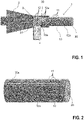
- figure 1 shows related to figure 2 an embodiment of a catheter 1 according to the invention, with an outer shaft 10 which extends from a proximal end section 10a to a distal end section (cut off, not shown) of the outer shaft 10 and has an outer side 10b.
- Proximal and distal mean here in the usual way that the proximal end section 10a is located closer to the doctor or user of the catheter 1, with the outer shaft 10 being inserted into the relevant vessel of the patient with the distal end section first.
- the catheter 1 also has a connector 2, which is connected to the proximal end section 10a of the outer shaft 10 or is molded onto it or is suitably formed on it and is designed to produce a fluid-conducting flow connection with a corresponding further connector.
- the connector 2 can, for example, be designed as a Luer lock connector and is fluidically connected to a lumen 20 of the outer shaft 10, through which, for example, a flow medium can be introduced into a balloon connected distally to the outer shaft 10 (e.g. to unfold the balloon).
- the connector 2 preferably has or is formed from a material processed, for example, by injection molding or a comparable shaping process, in which the proximal end section 10a of the outer shaft 10 is embedded together with a printed circuit board 3, with electrical conductors on the outside 10b of the outer shaft 10 11 are printed, each contacting an associated conductor track 12 of the printed circuit board 3, so that the conductors 11 are each electrically conductively connected to the respectively associated conductor track 12.
- the conductors 11 are conductors 11 printed from an electrically conductive ink.
- the conductor tracks 12 each have an area 12a in which the respective conductor track 12 is arranged on a surface 3a of the circuit board 3 and overlaps there with the associated printed conductor 11, so that electrically conductive contacts between the conductor tracks 12 and the conductors 11 result.
- the surface 3a of the printed circuit board 3 faces the outside 10b of the outer shaft 10, on which the conductors 11 are printed.
- the printed circuit board 3 would actually cover the underlying sections of the conductors 11 or conductor tracks 12. These are nevertheless drawn in to identify the structure.
- the printed circuit board 3 preferably has an angular shape, with a first section 30 of the printed circuit board 3 running at an angle, in particular at right angles, to a second section 31 of the printed circuit board 3 .
- Said overlapping areas 12a are provided at one end of the first section 30, whereas an end section of the second section 31 of the printed circuit board 3 is connected to a connector 4, via which the conductor tracks 12 (and thus the conductors 11) can be contacted in an electrically conductive manner.
- the conductor tracks 12 Preferably, at least in the areas 12a, the conductor tracks 12 have a width that is greater than a width of the conductor 11 perpendicular to the longitudinal direction of the conductor 11 or conductor tracks 12.
- the printed circuit board 3 can be formed from a polyimide, for example, and can have a thickness in the range from 0.03 mm to 0.1 mm, in particular 0.05 mm.
- the conductor tracks 12 can be etched in a known manner.
- the male or female connector 4 is prepared with a circuit board 3 in advance.
- the contact connections between the conductor tracks 12 of the printed circuit board 3 and the printed ink lines 11 are realized or maintained due to the pressure and the form fit of the material of the connector 2.
- a possible course of the method for manufacturing the catheter 1 is in the Figures 2 to 6 played back.
- the outer shaft 10 of the catheter 1 can be prepared by printing the necessary conductors 11 onto the outside 10b of the outer shaft with the aid of electrically conductive ink.
- the width, thickness and the ink material can be varied depending on the requirements (cf. figure 2 ).
- the printed circuit board 3 is provided (for example made of polyimide film, 0.05 mm thick) and the necessary conductor tracks 12 are etched or are formed thereon.
- the width of the conductor tracks 12 should preferably be greater than the width of the printed lines 11 (cf. 3 ).
- the printed circuit board 3 is connected to a connector 4 (e.g. by soldering).
- a connector 4 e.g. by soldering
- an HDMI-D connector with a width of 6.4 mm and a height of 2.8 mm can be used as the connector 4 .
- the circuit board 3 is then together with the connector 4 according to figure 4 fixed on the outside 10b of the outer socket 10 (for example by means of a shrink tube), so that the above-described overlap between the conductor tracks 12 and the printed lines 11 on the outer socket 10 results.
- the prepared arrangement according to figure 4 (PCB 3 with connector 4 and outer shaft 10) is finally placed in an injection mold and the connector 2 is molded onto the assembly.
- the heat-shrink tubing which is preferably made of thin polytetrafluoroethylene, is not removed but overmolded.
- a possible embodiment of the connector 2 is in the Figures 5 and 6 shown, in which case the connector 2 is designed as a Luer lock connector.
- Other connector types can of course also be realized with the invention.
- FIGS 5 and 6 each show the connector 4 for better visibility extends schematically in the plane of the page. In the figure 6 the connector 4 would actually extend perpendicularly to the plane of the page.
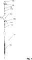
- FIG 7 shows an embodiment of the invention as a catheter 101 for the implantation of a self-expanding stent 150.
- the catheter 101 has two mutually movable catheter shafts 110a and 110b, wherein the self-expanding stent 150 arranged between the outer and inner shaft 110b is released by pulling back the outer shaft 110a.
- both the outer shaft 110a and the inner shaft 110b have a connector 120a or 120b at their proximal end.
- the two connectors 120a, 120b are designed in such a way that a fluid for flushing the lumen can be introduced via them (connector 120a is designed for supplying a fluid for flushing the lumen between outer shaft 110a and inner shaft 110b, connector 120b is for supplying a fluid to the Flushing the lumen of the inner shaft 110b configured).
- Connectors 120a and 120b are analogous to the embodiment of FIGS Figures 1 to 4 designed to connect the printed electrical conductors 111a and 111b on the catheter shafts 110a and 10b via a printed circuit board to the respective plug connectors 104a and 104b.
- the present invention advantageously offers a "two in one design” in which, for example, a Luer connector is provided with a second function (electrical connection between circuit board/connector and printed lines), which improves handling for the doctor.
- the invention also enables a secure electrical connection between catheter-side printed lines and an external component (e.g. measuring device, power supply, etc.) to be connected thereto.
- an external component e.g. measuring device, power supply, etc.
Landscapes
- Health & Medical Sciences (AREA)
- Life Sciences & Earth Sciences (AREA)
- Engineering & Computer Science (AREA)
- Biomedical Technology (AREA)
- Veterinary Medicine (AREA)
- Animal Behavior & Ethology (AREA)
- Public Health (AREA)
- Heart & Thoracic Surgery (AREA)
- General Health & Medical Sciences (AREA)
- Hematology (AREA)
- Anesthesiology (AREA)
- Pulmonology (AREA)
- Biophysics (AREA)
- Cardiology (AREA)
- Oral & Maxillofacial Surgery (AREA)
- Transplantation (AREA)
- Vascular Medicine (AREA)
- Media Introduction/Drainage Providing Device (AREA)
Description
- Die Erfindung betrifft einen Katheter, insbesondere einen Ballonkatheter. Die Erfindung wird hauptsächlich am Beispiel eines Ballonkatheters zur Durchführung einer Angioplastie oder Implantation eines Stents beschrieben, ist jedoch nicht darauf beschränkt sondern für jeden vaskulären Katheter geeignet.
- Ballonkatheter werden z.B. eingesetzt, um im Rahmen einer Angioplastie eine Stenose mittels eines Stents aufzuweiten, der auf einem Ballon des Ballonkatheters angeordnet ist und mittels des Ballonkatheters zum Zielort transportiert wird und dort mittels des Ballons aufgeweitet wird bzw. im Gefäß zur Beseitigung der Engstelle verankert wird. Die vorliegende Erfindung ist jedoch auch auf andere Katheter anwendbar.
- Bei derartigen Kathetern besteht oftmals die Herausforderung, eine auf dem Katheter bzw. Ballon angeordnete elektronische Komponente, z.B. einen Sensor zum Messen eines Durchmessers des Ballons, geeignet elektrisch zu kontaktieren.
- Oftmals werden hierbei in komplexen Verfahren und Lötvorgängen elektrische Leitungen entlang des Katheters verlegt und über Lötverbindungen mit elektrischen Anschlüssen bzw. Steckern am proximalen Ende des Katheters verbunden.
- Hierbei besteht insbesondere bei gedruckten elektrischen Leitern die Problematik, dass sich derartige elektrische Leiter aus gedruckten Tinten nur äußerst schwierig über herkömmliche Lötverfahren kontaktieren lassen. Lötverfahren sind dabei insbesondere aufgrund der hohen Temperaturen wegen der vergleichsweise temperatursensitiven Kunststoffmaterialien von Kathetern problematisch. Siehe zum Beispiel
US2015105659 ,US2016270732 ,US2007219551 oderUS2019245310 . - Der vorliegenden Erfindung liegt daher hiervon ausgehend die Aufgabe zugrunde, einen Katheter und ein Verfahren zur Herstellung eines solchen Katheters bereitzustellen, der bzw. das hinsichtlich der oben dargelegten Problematik verbessert ist.
- Diese Aufgabe wird durch einen Katheter mit den Merkmalen des Anspruchs 1 gelöst. Vorteilhafte Ausgestaltungen des Katheters sind in den entsprechenden Unteransprüchen angegeben und werden nachfolgend beschrieben.
- Gemäß Anspruch 1 wird ein Katheter offenbart, mit:
- einem Katheterschaft, der sich von einem proximalen Endabschnitt zu einem distalen Endabschnitt des Katheterschafts erstreckt und eine Außenseite aufweist, und
- einem mit dem proximalen Endabschnitt des Katheterschaftes verbundenen Verbinder.
- Erfindungsgemäß ist hierbei vorgesehen, dass der Verbinder ein Material aufweist, mit dem der proximale Endabschnitt des Katheterschaftes umgeben ist, wobei auf die Außenseite des Katheterschaftes zumindest ein elektrischer Leiter aufgedruckt ist, wobei der mindestens eine elektrische Leiter eine Leiterbahn einer Leiterplatte mechanisch kontaktiert, die in das Material des Verbinders eingebettet ist, so dass der mindestens eine elektrische Leiter und die mindestens eine Leiterbahn elektrisch leitend verbunden sind.
- Gemäß einer Ausführungsform ist der Erfindung steht der Verbinder mit einem Lumen des Katheterschaftes in Strömungsverbindung, so dass über den Verbinder ein fluides Medium in das Lumen des Katherschaftes einleitbar ist. Dies gilt insbesondere, wenn der Katheterschaft als Außenschaft eines Ballonkatheters ausgebildet ist. In dem Fall wird über den Verbinder ein Fluid zum Befüllen des Ballons in das Lumen des Außenschaft geführt. Alternativ kann der Verbinder am proximalen Ende eines Innenschaftes angeordnet sein und derart ausgestaltet sein, dass ein fluides Medium zum Spülen des Lumens des Innenschaftes einleitbar ist.
- Bei einem Katheter zur Implantation einer selbstexpandierenden Prothese (z.B. ein selbstexpandierender Stent) kann der Verbinder am proximalen Ende eines Außenschaftes und/oder eines Innenschaftes angeordnet werden. Auch in diesen Fällen kann der Verbinder mit dem Lumen des Außen- und/oder Innenschaftes derart in Strömungsverbindung stehen, dass über den Verbinder ein fluides Medium zum Spülen der Lumen einleitbar ist.
- Besonders bevorzugt ist vorgesehen, dass es sich bei dem Verbinder um einen Luer-Lock-Verbinder handelt.
- Mit dem erfindungsgemäßen Design wird bei den genannten Ausgestaltungen somit auf vorteilhafte Weise die aktuelle Inflation-Deflation-Funktion oder Spül-Funktion der Verbinder, insbesondere der Luer-Lock-Verbindungen, mit einem integrierten (mit der Leiterplatte verbundenen) Steckverbinder und ggf. einem dazu gehörenden Konnektor ergänzt.
- Diese Erfindung beschreibt somit ein hochintegriertes Konzept zur sicheren und preiswerten elektrischen Verbindungen zwischen Leiterbahnen und gedruckten elektrisch leitenden Tinten.
- Gemäß einer bevorzugten Ausführungsform der Erfindung ist vorgesehen, dass der proximale Endabschnitt des Katheterschaftes mit dem Material des Verbinders umspritzt ist.
- Weiterhin ist gemäß einer bevorzugten Ausführungsform der Erfindung vorgesehen, dass das Material des Verbinders ein thermoplastische Kunststoff ist.
- Im Prinzip kommen für die Erfindung alle thermoplastischen Kunststoffe in Frage, die für Medizinprodukte geeignet sind und in einem Spritzgußverfahren verarbeitet werden können, dessen Temperatur die Funktionalität der Leiterbahnen oder einer Leiterplatte nicht beeinflußt. Dies sind insbesondere ABS (Acrylnitrile butaden styrene), ABS-PC (Acrylnitrile butaden styrene + polycarbonate blend), ANMA (Acrlynitirle methyl acrylate copolymer), CAP (Cellulose acetetate propionate), COC (cyclic olefin copolymer), Copolyester, LCP (Liquid crystal polyester), MABS (Methylmethacrylate acrylnitirle butadien styrene), Polyamide (transparent, PA11, PA12, PA6, PA66), PBT (Polybutylene terephthalate), PC (Polycarbonate), PC + Polyester (Polycarbonate + polyester blend), PCTA (Polycyclohexylenedimethylene tere/isophthalate copolyester), PCTG (Polycyclohexylenedimethylene terephthalate glycol copolymer), HDPE (high density polyethylene), LLDPE (linear low density polyethylene), MDPE (medium denisty Polyethylene), PEBA (Polyester blockamide, thermoplastic polyamide-polyether elastomer mit verschiedener Shore Härte), PEI (Polyether imide), PEI+ PCE (Polyetherimide + polycarbonate ester blend), PET (Polyethylene terephthalate), PFA (Perfluorakoxyethylene), PGA (Polyglycolic acid), PLA (Polylactic acid), PMMA (Polymethylmethacylate), PMP (Polymethylpentene), POM (Polyoxymethylene), PP (Polypropylene), PPE + PS (Polyphenylene ether + Polystyrene), PPSU (Polyphenylsulfione), PS (Polystyrene), PSU (Polysulfone), PVC (Polyvinly chloride, pasticized), PCC-P (Polyvinyl chloride elastomer, pasticized), PVDF (Polyvinylidene difluoride), SAN (Acrylnitrile styrene coploymer), SB (Styrene butadiene copolymer), SEBS (Styrene ethylene butylenen styrene block copolymer, verschiedener Härte), SMMA (Styrene methyl methycrylate copolymer), SRP (self reinforcing polyphenylene), TPC (Thermoplastic copolyester-ether elastomer verschiedener Härte)), TPU (thermoplastic polyurethane elastomer verschiedener Härte), TPV (thermoplastic vulcanizate, verschiedener Härte).
- Weiterhin ist gemäß einer bevorzugten Ausführungsform der Erfindung vorgesehen, dass der mindestens eine elektrische Leiter und die Leiterbahn überlappend angeordnet sind, wobei vorzugsweise die Leiterbahn und der mindestens eine elektrische Leiter auf der Außenseite des Katheterschaftes in einer gemeinsamen Längserstreckungsrichtung einander überlappen, also insbesondere nicht einander kreuzend angeordnet sind.
- Weiterhin ist gemäß einer bevorzugten Ausführungsform der Erfindung vorgesehen, dass die Leiterbahn in einem Bereich der Leiterbahn, in dem die Leiterbahn mit dem mindestens einen elektrischen Leiter überlappt, auf einer Oberfläche der Leiterplatte angeordnet ist, wobei die Oberfläche der Außenseite des Katheterschaftes zugewandt ist bzw. auf dieser angeordnet ist.
- Abseits der Überlappung bzw. des Kontaktes zwischen dem mindestens einen elektrischen Leiter und der Leiterbahn sind der mindestens eine elektrische Leiter und die mindestens eine Leiterbahn vorzugsweise geeignet elektrisch isoliert. Bei der Leiterplatte kann diese Isolierung durch das umgebende Material des Verbinders sichergestellt werden.
- Weiterhin ist gemäß einer bevorzugten Ausführungsform der Erfindung vorgesehen, dass die Leiterplatte einen ersten und einen damit verbundenen zweiten Abschnitt aufweist, wobei die beiden Abschnitte winklig zueinander angeordnet sind, insbesondere rechtwinklig. Diese Ausgestaltung erlaubt eine besonders einfache Kontaktierung bzw. Verbindung des Katheters, insbesondere über einen Steckverbinder, mit einer Einrichtung zur Applikation, Auswertung und/oder Steuerung elektrischer Signale.
- Weiterhin ist gemäß einer bevorzugten Ausführungsform der Erfindung vorgesehen, dass der besagte Bereich der Leiterbahn an einem Ende des ersten Abschnitts angeordnet ist.
- Weiterhin ist gemäß einer bevorzugten Ausführungsform der Erfindung vorgesehen, dass die Leiterplatte mit einem Steckverbinder verbunden ist, über den die Leiterbahn elektrisch leitend kontaktierbar ist. Bevorzugt ist hierbei der Steckverbinder mit einem Endabschnitt des zweiten Abschnitts der Leiterplatte verbunden, insbesondere durch eine Lötverbindung. Aufgrund der winkligen Anordnung bzw. Ausgestaltung der beiden Abschnitte der Leiterplatte kann der Steckverbinder insbesondere quer bzw. in einem Winkel zur axialen Richtung des Katheters aus dem Verbinder herausgeführt sein.
- Weiterhin ist gemäß einer bevorzugten Ausführungsform der Erfindung vorgesehen, dass die Leiterbahn in dem besagte Bereich der Leiterbahn, der mit dem mindestens einen elektrischen Leiter überlappt, eine Breite aufweist, die größer ist als eine Breite des mindestens einen elektrischen Leiters. Hier ist jeweils die Breite senkrecht zur Längserstreckungsrichtung der Leiterbahn bzw. des Leiters gemeint.
- Weiterhin ist gemäß einer bevorzugten Ausführungsform der Erfindung vorgesehen, dass die Leiterplatte aus Polyimid gebildet ist. Weiterhin kann die Leiterplatte eine Stärke im Bereich von z. B. 0,03 mm bis 0,1 mm aufweisen.
- Vorzugsweise handelt es sich bei dem Katheter um einen Ballonkatheter, wobei insbesondere der mindestens eine elektrische Leiter mit einem Sensor des Ballonkatheters verbunden ist, insbesondere mit einem auf einem Ballon des Ballonkatheters angeordneten Sensor.
- Vorstehend wurde die Erfindung anhand einer Leiterbahn und eines gedruckten elektrischen Leiters des Katheterschaftes beschrieben. Es können natürlich eine Mehrzahl an separaten Leiterbahnen der Leiterplatte und eine Mehrzahl an gedruckten Leitern des Katheterschaftes in der hierein beschriebenen Weise miteinander mechanisch und damit elektrisch leitend in Kontakt stehen.
- Ein weiterer Aspekt der vorliegenden Erfindung betrifft ein Verfahren zur Herstellung eines Katheters (insbesondere zur Herstellung eines erfindungsgemäßen Katheters), aufweisend die Schritte:
- Aufdrucken zumindest eines elektrischen Leiters auf eine Außenseite eines Katheterschaftes des Katheters mit einer elektrisch leitfähigen Tinte,
- Bereitstellen einer Leiterplatte, die zumindest eine Leiterbahn aufweist,
- Anordnen der Leiterplatte auf der Außenseite des Katheterschaftes im Bereich eines proximalen Endabschnitts des Außenschaftes, so dass die Leiterbahn den mindestens einen elektrischen Leiter mechanisch und damit elektrisch leitend kontaktiert und insbesondere mit diesem überlappt, und
- Umgeben der Leiterplatte und des proximalen Endabschnitts des Katheterschaftes mit einem Material zum Ausbilden eines mit dem proximalen Endabschnitt des Außenschaftes verbundenen Verbinders.
- Hinsichtlich des Anordnens der Leiterplatte bezüglich der Außenseite des Katheterschaftes kann weiterhin vorgesehen sein, dass die Leiterplatte auf der Außenseite fixiert wird, z.B. mittels eines Schrumpfschlauchs.
- Gemäß einer Ausführungsform des Verfahrens ist vorzugsweise vorgesehen, dass ein Steckverbinder mit der Leiterplatte verbunden wird, so dass die Leiterbahn (und damit später der mindestens eine gedruckte elektrische Leiter) über den Steckverbinder elektrisch kontaktierbar ist, wobei insbesondere der Steckverbinder mit der Leiterplatte verbunden wird, bevor die Leiterplatte auf der Außenseite des Katheterschaftes angeordnet wird (sowie insbesondere bevor die Leiterplatte und der proximale Endabschnitt des Katheterschaftes mit dem Material des Verbinders umgeben werden).
- Gemäß einer weiteren Ausführungsform des Verfahrens ist vorgesehen, dass zum Umgeben des proximalen Endabschnitts des Katheterschaftes und der Leiterplatte mit dem Material des Verbinders der proximale Endabschnitt des Katheterschaftes und die Leiterplatte in einer Form (z. B. Spritzgussform) angeordnet werden und in der Form mit dem Material umgeben werden, insbesondere mittels Spritzgießen umspritzt werden, d. h., in das Material durch Spritzgießen eingegossen werden.
- Auch bei dem Verfahren können natürlich mehrere Leiterbahnen der Leiterplatte mit je einem elektrischen Leiter des Katheterschaftes verbunden bzw. kontaktiert werden.
- Im Folgenden sollen Ausführungsformen der Erfindung sowie weitere Merkmale und Vorteile der Erfindung anhand der Figuren erläutert werden. Es zeigen:
- Fig. 1
- eine schematische Ausführungsform eines erfindungsgemäßen Katheters,
- Fig. 2
- eine perspektivische Ansicht eines Außenschaftes des in der
Fig. 1 gezeigten Katheters, wobei auf eine Außenseite des Außenschaftes elektrische Leiter aus einer elektrisch leitfähigen Tinte aufgedruckt sind, - Fig. 3
- eine Draufsicht auf eine Oberfläche einer Leiterplatte des in den
Figuren 1 und 2 gezeigten Katheters, wobei auf der Oberfläche Leiterbahnen angeordnet sind, - Fig. 4
- eine schematische Ansicht des Anordnens der Leiterplatte auf der Außenseite des Außenschaftes, so dass die Leiterbahnen auf der Oberfläche der Leiterplatte die Leiter auf der Außenseite des Außenschaftes kontaktieren und mit diesen überlappen (vgl. Detail der
Figur 4 ), - Fig. 5
- eine schematische Ansicht des fertigen Katheters, wobei ein Verbinder, insbesondere in Form eines Luer-Lock-Verbinders auf die Anordnung gemäß
Figur 4 mittels Spritzgießen aufgebracht worden ist, so dass der Verbinder die Leiterplatte und den proximalen Endabschnitt des Außenschaftes umgibt und die Leiterplatte bezüglich des Außenschaftes festlegt, und zwar unter Sicherstellung der elektrischen Kontakte zwischen den Leiterbahnen und dem jeweils zugeordneten gedruckten Leiter des Außenschaftes, - Fig. 6
- eine schematische Schnittansicht des Verbinders entlang der Linie A-A der
Figur 5 , und - Fig. 7
- eine weitere schematische Ausführungsform eines erfindungsgemäßen Katheters zur Implantation eines selbstexpandierenden Stents.
-
Figur 1 zeigt im Zusammenhang mitFigur 2 eine Ausführungsform eines erfindungsgemäßen Katheters 1, mit einem Außenschaft 10, der sich von einem proximalen Endabschnitt 10a zu einem distalen Endabschnitt (abgeschnitten, nicht dargestellt) des Außenschafts 10 erstreckt und eine Außenseite 10b aufweist. Proximal und distal bedeuten hierbei in der üblichen Weise, dass der proximale Endabschnitt 10a näher am Arzt bzw. Verwender des Katheters 1 gelegen ist, wobei der Außenschaft 10 mit dem distalen Endabschnitt voran in das betreffende Gefäß des Patienten eingeführt wird. - Der Katheter 1 weist weiterhin einen Verbinder 2 auf, der mit dem proximalen Endabschnitt 10a des Außenschaftes 10 verbunden ist bzw. an diesen angespritzt oder geeignet angeformt ist und zur Herstellung einer fluidleitenden Strömungsverbindung mit einem korrespondierenden weiteren Verbinder ausgebildet ist.
- Der Verbinder 2 kann z.B. als Luer-Lock-Verbinder ausgebildet sein und ist mit einem Lumen 20 des Außenschafts 10 fluidtechnisch verbunden, durch das z.B. ein Strömungsmittel in einen distal mit dem Außenschaft 10 verbundenen Ballon einleitbar ist (z.B. zum Entfalten des Ballons).
- Vorzugsweise weist der Verbinder 2 ein z.B. durch Spritzgießen oder eine vergleichbares Formgebungsverfahren verarbeitetes Material auf bzw. ist aus diesem gebildet, in das der proximale Endabschnitt 10a des Außenschaftes 10 zusammen mit einer Leiterplatte 3 eingebettet ist, wobei auf die Außenseite 10b des Außenschaftes 10 elektrische Leiter 11 aufgedruckt sind, die jeweils eine zugeordnete Leiterbahn 12 der Leiterplatte 3 kontaktieren, so dass die Leiter 11 jeweils elektrisch leitend mit der jeweils zugeordneten Leiterbahn 12 verbunden sind. Bei den Leitern 11 handelt es sich um aus einer elektrisch leitfähigen Tinte gedruckte Leiter 11.
- Wie insbesondere anhand des Details der
Figur 4 ersichtlich ist, ist vorgesehen, dass die elektrischen Leiter 11 und die Leiterbahnen 12 überlappend angeordnet sind, und zwar vorzugsweise jeweils in der gemeinsamen Längserstreckungsrichtung. - Mit anderen Worten weisen die Leiterbahnen 12 jeweils einem Bereich 12a auf, in dem die jeweilige Leiterbahn 12 an einer Oberfläche 3a der Leiterplatte 3 angeordnet ist und dort mit dem zugeordneten gedruckten Leiter 11 überlappt, so dass elektrisch leitfähige Kontakte zwischen den Leiterbahnen 12 und den Leitern 11 resultieren. Dabei ist die Oberfläche 3a der Leiterplatte 3 der Außenseite 10b des Außenschaftes 10, auf der die Leiter 11 gedruckt sind, zugewandt. In den
Figuren 1 und4 würde die Leiterplatte 3 eigentlich die darunterliegenden Abschnitte der Leiter 11 bzw. Leiterbahnen 12 verdecken. Diese sind dennoch zur Kenntlichmachung der Struktur eingezeichnet. - Die Leiterplatte 3 weist vorzugsweise eine winklige Gestalt auf, wobei ein erster Abschnitt 30 der Leiterplatte 3 winklig, insbesondere rechtwinklig, zu einem zweiten Abschnitt 31 der Leiterplatte 3 verläuft.
- Die besagten Überlappungsbereiche 12a sind dabei an einem Ende des ersten Abschnitts 30 vorgesehen, wohingegen ein Endabschnitt des zweiten Abschnitts 31 der Leiterplatte 3 mit einem Steckverbinder 4 verbunden ist, über den die Leiterbahnen 12 (und damit die Leiter 11) elektrisch leitend kontaktierbar sind. Vorzugsweise weisen die Leiterbahnen 12 zumindest in den Bereichen 12a eine Breite auf, die größer ist als eine Breite der Leiter 11 senkrecht zur Längserstreckungsrichtung der Leiter 11 bzw. Leiterbahnen 12.
- Die Leiterplatte 3 kann z.B. aus einem Polyimid gebildet sein und kann eine Stärke im Bereich von 0,03 mm bis 0,1 mm aufweisen, insbesondere 0,05 mm. Die Leiterbahnen 12 können in bekannter Weise geätzt sein.
- Vorzugsweise wird der männliche oder weibliche Steckverbinder 4 vorab mit einer Leiterplatte 3 vorbereitet. Durch den Spritzprozess (oder durch ein vergleichbares Formgebungsverfahrens zur Erzeugung des Verbinders 2) werden die Kontakt-Verbindungen zwischen den Leiterbahnen 12 der Leiterplatte 3 und den gedruckten Tinten-Leitungen 11 aufgrund des Drucks und des Formschlusses des Materials des Verbinders 2 realisiert bzw. aufrecht erhalten.
- Ein möglicher Ablauf des Verfahrens zur Herstellung des Katheters 1 ist in den
Figuren 2 bis 6 wiedergegeben. - Zunächst kann der Außenschaft 10 des Katheters 1 vorbereitet werden, indem die nötigen Leiter 11 mit Hilfe von elektrisch leitender Tinte auf die Außenseite 10b des Außenschafts gedruckt werden. Die Breite, Dicke und das Tintenmaterial sind dabei je nach Anforderungen variierbar (vgl.
Figur 2 ). - Sodann wird die Leiterplatte 3 bereitgestellt (z.B. aus Polyimid-Folie, 0,05 mm dick) und die nötigen Leiterbahnen 12 werden geätzt bzw. sind darauf ausgebildet. Die Breite der Leiterbahnen 12 soll dabei vorzugsweise größer als die Breite der gedruckten Leitungen 11 sein (vgl.
Fig. 3 ). - Weiterhin wird die Leiterplatte 3 mit einem Steckverbinder 4 verbunden (z.B. durch Löten). Als Steckverbinder 4 kann z.B. ein HDMI-D-Stecker mit 6,4 mm Breite und 2,8 mm Höhe verwendet werden.
- Die Leiterplatte 3 wird dann zusammen mit dem Steckverbinder 4 gemäß
Figur 4 auf der Außenseite 10b des Außenschaftes 10 fixiert (z.B. mittels eines Schrumpfschlauches), so dass die oben beschriebene Überlappung zwischen den Leiterbahnen 12 und den gedruckten Leitungen 11 auf dem Außenschaft 10 resultiert. - Die vorbereitete Anordnung gemäß
Figur 4 (Leiterplatte 3 mit Steckverbinder 4 und Außenschaft 10) wird schließlich in einer Spritzgussform angeordnet und der Verbinder 2 wird an die Anordnung angespritzt. Der vorzugsweise aus dünnen Polytetrafluorethylen ausgeführte Schrumpfschlauch wird dabei nicht entfernt sondern mit umspritzt. - Eine mögliche Ausgestaltung des Verbinders 2 ist in den
Figuren 5 und 6 dargestellt, wobei hier der Verbinder 2 als Luer-Lock-Verbinder ausgestaltet ist. Andere Verbindertypen sind natürlich auch mit der Erfindung realisierbar. - Die
Figuren 5 und 6 zeigen jeweils den Steckverbinder 4 der besseren Sichtbarkeit halber schematisch in der Blattebene erstreckt. In derFigur 6 würde sich der Steckverbinder 4 eigentlich senkrecht zur Blattebene erstrecken. -
Figur 7 zeigt eine Ausführungsform der Erfindung als Katheter 101 zur Implantation eines selbstexpandierbaren Stents 150. Der Katheter 101 weist zwei gegeneinander bewegliche Katheterschäfte 110a und 110b auf, wobei durch Zurückziehen des Außenschaftes 110a der zwischen Außen- und Innenschaft 110b angeordnete selbstexpandierende Stent 150 freigesetzt wird. - In dieser Ausführungsform der Erfindung weisen sowohl der Außenschaft 110a als auch der Innenschaft 110b an ihrem proximalen Ende einen Verbinder 120a bzw. 120b auf. Die beiden Verbinder 120a, 120b sind derart ausgestaltet, dass über sie ein Fluid zum Spülen des Lumens eingeleitet werden kann (Verbinder 120a ist zur Zufuhr eines Fluids zum Spülen des Lumens zwischen Außenschaft 110a und Innenschaft 110b ausgestaltet, Verbinder 120b ist zur Zufuhr eines Fluids zum Spülen des Lumens des Innenschaftes 110b ausgestaltet).
- Die Verbinder 120a und 120b sind analog zur Ausführungsform nach den
Figuren 1 bis 4 zur Verbindung der aufgedruckten elektrischen Leiter 111a und 111b auf den Katheterschäften 110a und 10b über eine Leiterplatte mit den jeweiligen Steckverbindern 104a und 104b ausgestaltet. - Die vorliegende Erfindung bietet mit Vorteil ein "two in one Design", bei dem z.B. ein Luer-Anschluss mit einer zweiten Funktion (elektrische Verbindung zwischen Leiterplatte/Steckverbinder und gedruckten Leitungen) bereitgestellt wird, was das Handling für den Arzt verbessert.
- Die Erfindung ermöglicht weiterhin eine sichere elektrische Verbindung zwischen katheterseitigen gedruckten Leitungen und einer damit zu verbindenden externen Komponente (z.B. Messgerät, Stromversorgung etc.).
Claims (16)
- Katheter (1), mit:- einem Katheterschaft (10, 110a, 110b), der sich von einem proximalen Endabschnitt (10a) zu einem distalen Endabschnitt des Katheterschafts (10, 110a, 110b) erstreckt und eine Außenseite (10b) aufweist, und- einem mit dem proximalen Endabschnitt (10a) des Katheterschaftes (10, 110a, 110b) verbundenen Verbinder (2, 120a, 120b), ,dadurch gekennzeichnet, dass
der Verbinder (2, 120a, 120b) ein Material aufweist, mit dem der proximale Endabschnitt (10a) des Katheterschaftes (10, 110a, 110b) umgeben ist, wobei auf die Außenseite (10b) des Katheterschaftes (10, 110a, 110b) zumindest ein elektrischer Leiter (11, 111a, 111b) aufgedruckt ist, wobei der mindestens eine elektrische Leiter (11, 111a, 111b) eine Leiterbahn (12) einer Leiterplatte (3) kontaktiert, die in das Material des Verbinders (2, 120a, 120b) eingebettet ist, so dass der mindestens eine elektrische Leiter (11, 111a, 111b) und die mindestens eine Leiterbahn (12) elektrisch leitend verbunden sind. - Katheter nach Anspruch 1, dadurch gekennzeichnet, dass der mindestens eine elektrische Leiter (11, 111a, 111b) aus einer ausgehärteten elektrisch leitfähigen Tinte gebildet ist.
- Katheter nach Anspruch 1 oder 2, dadurch gekennzeichnet, dass der proximale Endabschnitt (10a) des Katheterschaftes (10, 110a, 110b) mit dem Material des Verbinders (2, 120a, 120b) umspritzt ist.
- Katheter nach einem der vorhergehenden Ansprüche, dadurch gekennzeichnet, dass das Material des Verbinders (2, 120a, 120b) aus einem thermoplastischen Kunststoff ist.
- Katheter nach einem der vorhergehenden Ansprüche, dadurch gekennzeichnet, dass der mindestens eine elektrische Leiter (11, 111a, 111b) und die Leiterbahn (12) überlappend angeordnet sind.
- Katheter nach Anspruch 5, dadurch gekennzeichnet, dass die Leiterbahn (12) in einem Bereich (12a) der Leiterbahn (12), in dem die Leiterbahn (12) mit dem mindestens einen elektrischen Leiter (11, 111a, 111b) überlappt, auf einer Oberfläche (3a) der Leiterplatte (3) angeordnet ist, wobei die Oberfläche (3a) der Außenseite (10b) des Katheterschaftes (10, 110a, 110b) zugewandt ist.
- Katheter nach einem der vorhergehenden Ansprüche, dadurch gekennzeichnet, dass die Leiterplatte (3) einen ersten und einen damit verbundenen zweiten Abschnitt (30, 31) aufweist, wobei die beiden Abschnitte (30, 31) winklig zueinander angeordnet sind.
- Katheter nach Anspruch 6 oder nach Anspruch 7 sofern rückbezogen auf Anspruch 6, dadurch gekennzeichnet, dass der besagte Bereich (12a) der Leiterbahn (12) an einem Ende des ersten Abschnitts (30) angeordnet ist.
- Katheter nach einem der vorhergehenden Ansprüche, dadurch gekennzeichnet, dass die Leiterplatte (3) mit einem Steckverbinder (4, 104a, 104b) verbunden ist, über den die Leiterbahn (12) elektrisch leitend kontaktierbar ist.
- Katheter nach den Ansprüchen 7 und 9, dadurch gekennzeichnet dass der Steckverbinder (4, 104a, 104b) mit einem Endabschnitt des zweiten Abschnitts (31) der Leiterplatte (3) verbunden ist.
- Katheter nach Anspruch 6 oder nach einem der Ansprüche 7 bis 10 soweit rückbezogen auf Anspruch 6, dadurch gekennzeichnet, dass die Leiterbahn (12) in dem besagte Bereich (12a) der Leiterbahn (12) eine Breite aufweist, die größer ist als eine Breite des mindestens einen elektrischen Leiters (11, 111a, 111b).
- Katheter nach einem der vorhergehenden Ansprüche, dadurch gekennzeichnet dass die Leiterplatte (3) aus Polyimid gebildet ist und/oder dass die Leiterplatte (3) eine Stärke im Bereich von 0,03 mm bis 0,1 mm aufweist.
- Katheter nach einem der vorhergehenden Ansprüche, dadurch gekennzeichnet, dass der Katheterschaft (10, 110a, 110b) ein Außenschaft (10a) eines Ballonkatheters ist und der Verbinder (2) zur Herstellung einer fluidleitenden Strömungsverbindung mit einem korrespondierenden weiteren Verbinder ausgebildet ist.
- Verfahren zum Herstellen eines Katheters (1), aufweisend die Schritte:- Aufdrucken zumindest eines elektrischen Leiters (11, 111a, 111b) auf eine Außenseite (10b) eines Katheterschaftes (10, 110a, 110b) des Katheters (1) mit einer elektrisch leitfähigen Tinte,- Bereitstellen einer Leiterplatte (3), die zumindest eine Leiterbahn (12) aufweist,- Anordnen der Leiterplatte (3) auf der Außenseite (10b) des Katheterschaftes (10, 110a, 110b) im Bereich eines proximalen Endabschnitts (10a) des Katheterschaftes (10, 110a, 110b), so dass die Leiterbahn (12) den mindestens einen elektrischen Leiter (11, 111a, 111b) kontaktiert, und- Umgeben der Leiterplatte (3) und des proximalen Endabschnitts (10a) des Katheterschaftes (10, 110a, 110b) mit einem Material zum Ausbilden eines mit dem proximalen Endabschnitt (10a) des Katheterschaftes (10, 110a, 110b) verbundenen Verbinders (2, 102a, 102b).
- Verfahren nach Anspruch 14, wobei ein Steckverbinder (4, 104a, 104b) mit der Leiterplatte (3) verbunden wird, so dass die Leiterbahn (12) über den Steckverbinder (4, 104a, 104b) elektrisch kontaktierbar ist, wobei insbesondere der Steckverbinder (4, 104a, 104b) mit der Leiterplatte (3) verbunden wird, bevor die Leiterplatte (3) auf der Außenseite (10b) des proximalen Endabschnitts (10a) des Katheterschaftes (10, 110a, 110b) angeordnet wird.
- Verfahren nach Anspruch 14 oder 15, wobei zum Umgeben des proximalen Endabschnitts (10a) des Katheterschaftes (10, 110a, 110b) und der Leiterplatte (3) mit dem besagten Material der proximale Endabschnitt (10a) des Katheterschaftes (10, 110a, 110b) und die Leiterplatte (3) in einer Spritzgussform angeordnet werden und in der Spritzgussform mit dem Material umspritzt werden.
Priority Applications (5)
| Application Number | Priority Date | Filing Date | Title |
|---|---|---|---|
| EP19191879.6A EP3777946B1 (de) | 2019-08-15 | 2019-08-15 | Luer-lock-system für digitale ballonkatheter |
| CN202080057345.4A CN114222546A (zh) | 2019-08-15 | 2020-07-20 | 用于数字球囊导管的鲁尔锁系统 |
| PCT/EP2020/070428 WO2021028154A1 (en) | 2019-08-15 | 2020-07-20 | Luer lock system for digital balloon catheters |
| EP20743134.7A EP4013478A1 (de) | 2019-08-15 | 2020-07-20 | Luer-lock-system für digitale ballonkatheter |
| US17/630,219 US20220280749A1 (en) | 2019-08-15 | 2020-07-20 | Catheter having connector with electrical conductor connections |
Applications Claiming Priority (1)
| Application Number | Priority Date | Filing Date | Title |
|---|---|---|---|
| EP19191879.6A EP3777946B1 (de) | 2019-08-15 | 2019-08-15 | Luer-lock-system für digitale ballonkatheter |
Publications (2)
| Publication Number | Publication Date |
|---|---|
| EP3777946A1 EP3777946A1 (de) | 2021-02-17 |
| EP3777946B1 true EP3777946B1 (de) | 2023-01-18 |
Family
ID=67658948
Family Applications (2)
| Application Number | Title | Priority Date | Filing Date |
|---|---|---|---|
| EP19191879.6A Active EP3777946B1 (de) | 2019-08-15 | 2019-08-15 | Luer-lock-system für digitale ballonkatheter |
| EP20743134.7A Withdrawn EP4013478A1 (de) | 2019-08-15 | 2020-07-20 | Luer-lock-system für digitale ballonkatheter |
Family Applications After (1)
| Application Number | Title | Priority Date | Filing Date |
|---|---|---|---|
| EP20743134.7A Withdrawn EP4013478A1 (de) | 2019-08-15 | 2020-07-20 | Luer-lock-system für digitale ballonkatheter |
Country Status (4)
| Country | Link |
|---|---|
| US (1) | US20220280749A1 (de) |
| EP (2) | EP3777946B1 (de) |
| CN (1) | CN114222546A (de) |
| WO (1) | WO2021028154A1 (de) |
Families Citing this family (1)
| Publication number | Priority date | Publication date | Assignee | Title |
|---|---|---|---|---|
| US11931066B2 (en) | 2021-02-25 | 2024-03-19 | Avent, Inc. | Directly connected smart invasive medical device assembly |
Family Cites Families (6)
| Publication number | Priority date | Publication date | Assignee | Title |
|---|---|---|---|---|
| US7713260B2 (en) * | 2003-09-11 | 2010-05-11 | Cook Incorporated | Catheter having an overmolded hub |
| US8147486B2 (en) * | 2003-09-22 | 2012-04-03 | St. Jude Medical, Atrial Fibrillation Division, Inc. | Medical device with flexible printed circuit |
| US20150105659A1 (en) * | 2008-11-11 | 2015-04-16 | Covidien Lp | Energy delivery device and methods of use |
| US8206374B2 (en) * | 2010-03-15 | 2012-06-26 | Medtronic Vascular, Inc. | Catheter having improved traceability |
| US20160270732A1 (en) * | 2015-03-17 | 2016-09-22 | Cathprint Ab | Low profile medical device with bonded base for electrical components |
| US10916903B2 (en) * | 2018-02-04 | 2021-02-09 | Creganna Unlimited Company | System having a cable assembly and plug and receptacle connectors |
-
2019
- 2019-08-15 EP EP19191879.6A patent/EP3777946B1/de active Active
-
2020
- 2020-07-20 EP EP20743134.7A patent/EP4013478A1/de not_active Withdrawn
- 2020-07-20 US US17/630,219 patent/US20220280749A1/en active Pending
- 2020-07-20 WO PCT/EP2020/070428 patent/WO2021028154A1/en unknown
- 2020-07-20 CN CN202080057345.4A patent/CN114222546A/zh active Pending
Also Published As
| Publication number | Publication date |
|---|---|
| CN114222546A (zh) | 2022-03-22 |
| WO2021028154A1 (en) | 2021-02-18 |
| EP3777946A1 (de) | 2021-02-17 |
| US20220280749A1 (en) | 2022-09-08 |
| EP4013478A1 (de) | 2022-06-22 |
Similar Documents
| Publication | Publication Date | Title |
|---|---|---|
| DE69832891T2 (de) | Ein männlicher verbinder mit einer kontinuierlichen oberfläche zur drahtführung und dessen verwendung | |
| DE69924082T2 (de) | Aktives schlankes Röhrchen und Verfahren zur Herstellung | |
| DE60225565T2 (de) | Katheter und methode zum herstellen eines katheters | |
| WO2015082328A1 (de) | Endoskopkopf und endoskop | |
| AU2017373953B2 (en) | Overmold technique for peel-away introducer design | |
| CH622870A5 (de) | ||
| DE3213776A1 (de) | Formteil mit ueberlappungsverbindung fuer eine herzschrittmacher-elektrodenleitung | |
| EP3777946B1 (de) | Luer-lock-system für digitale ballonkatheter | |
| DE10251639A1 (de) | Sensorelement-Vorrichtung für einen kapazitiven Berührungsschalter mit einem elektrisch leitfähigen Körper und Verfahren zur Herstellung eines solchen Körpers | |
| DE112015002449T5 (de) | Katheter, Katheterherstellungsformteil, Katheterherstellungsverfahren | |
| WO2017215916A1 (de) | Sensoranordnung | |
| DE4137628C1 (de) | ||
| EP2250010B1 (de) | Fühler zum erfassen einer physikalischen grösse und verfahren zur herstellung des fühlers | |
| WO2015172890A1 (de) | Medizintechnisches messsystem und verfahren zur herstellung des messsystems | |
| DE3820348C2 (de) | ||
| DE60110791T2 (de) | Vorrichtung aus thermoplastischem material und zugehöriges zweistufiges giessverfahren | |
| EP2384785B1 (de) | Verfahren zum Herstellen einer Elektrodenstruktur sowie Elektrodenstruktur für eine neuronale Schnittstelle | |
| DE4320702A1 (de) | Medizinisch-chirurgische Vorrichtung | |
| DE10032849C2 (de) | Elektrisches Gerät mit einem Gehäuse aus verfestigtem polymeren Werkstoff | |
| DE102012200918B4 (de) | Verfahren zum Herstellen einer thermoplastischen Vorrichtung mit einer Steckerkavität | |
| WO2018108364A1 (de) | Getriebesteuerungseinrichtung, insbesondere für ein kraftfahrzeug, und verfahren zum herstellen eines steckergehäuses | |
| DE102018105774B4 (de) | Dichtumspritzter elektrischer Leiter und Verfahren zu dessen Herstellung | |
| DE10133731A1 (de) | Verfahren zum Herstellen eines elktrischen Endprodukts, welches Löt-oder Schweißstellen aufweist | |
| DE19804159B4 (de) | Verbindungsmuffe und Verfahren zu ihrer Herstellung | |
| DE102008003372B4 (de) | Verfahren zur Herstellung eines mehrlagigen zwei- oder dreidimensionalen Schaltungsträgers |
Legal Events
| Date | Code | Title | Description |
|---|---|---|---|
| PUAI | Public reference made under article 153(3) epc to a published international application that has entered the european phase |
Free format text: ORIGINAL CODE: 0009012 |
|
| STAA | Information on the status of an ep patent application or granted ep patent |
Free format text: STATUS: THE APPLICATION HAS BEEN PUBLISHED |
|
| AK | Designated contracting states |
Kind code of ref document: A1 Designated state(s): AL AT BE BG CH CY CZ DE DK EE ES FI FR GB GR HR HU IE IS IT LI LT LU LV MC MK MT NL NO PL PT RO RS SE SI SK SM TR |
|
| AX | Request for extension of the european patent |
Extension state: BA ME |
|
| STAA | Information on the status of an ep patent application or granted ep patent |
Free format text: STATUS: REQUEST FOR EXAMINATION WAS MADE |
|
| 17P | Request for examination filed |
Effective date: 20210805 |
|
| RBV | Designated contracting states (corrected) |
Designated state(s): AL AT BE BG CH CY CZ DE DK EE ES FI FR GB GR HR HU IE IS IT LI LT LU LV MC MK MT NL NO PL PT RO RS SE SI SK SM TR |
|
| GRAP | Despatch of communication of intention to grant a patent |
Free format text: ORIGINAL CODE: EPIDOSNIGR1 |
|
| STAA | Information on the status of an ep patent application or granted ep patent |
Free format text: STATUS: GRANT OF PATENT IS INTENDED |
|
| INTG | Intention to grant announced |
Effective date: 20220414 |
|
| GRAJ | Information related to disapproval of communication of intention to grant by the applicant or resumption of examination proceedings by the epo deleted |
Free format text: ORIGINAL CODE: EPIDOSDIGR1 |
|
| STAA | Information on the status of an ep patent application or granted ep patent |
Free format text: STATUS: REQUEST FOR EXAMINATION WAS MADE |
|
| INTC | Intention to grant announced (deleted) | ||
| GRAP | Despatch of communication of intention to grant a patent |
Free format text: ORIGINAL CODE: EPIDOSNIGR1 |
|
| STAA | Information on the status of an ep patent application or granted ep patent |
Free format text: STATUS: GRANT OF PATENT IS INTENDED |
|
| INTG | Intention to grant announced |
Effective date: 20221018 |
|
| GRAS | Grant fee paid |
Free format text: ORIGINAL CODE: EPIDOSNIGR3 |
|
| GRAA | (expected) grant |
Free format text: ORIGINAL CODE: 0009210 |
|
| STAA | Information on the status of an ep patent application or granted ep patent |
Free format text: STATUS: THE PATENT HAS BEEN GRANTED |
|
| AK | Designated contracting states |
Kind code of ref document: B1 Designated state(s): AL AT BE BG CH CY CZ DE DK EE ES FI FR GB GR HR HU IE IS IT LI LT LU LV MC MK MT NL NO PL PT RO RS SE SI SK SM TR |
|
| REG | Reference to a national code |
Ref country code: GB Ref legal event code: FG4D Free format text: NOT ENGLISH |
|
| REG | Reference to a national code |
Ref country code: DE Ref legal event code: R096 Ref document number: 502019006810 Country of ref document: DE |
|
| REG | Reference to a national code |
Ref country code: CH Ref legal event code: EP |
|
| REG | Reference to a national code |
Ref country code: AT Ref legal event code: REF Ref document number: 1544336 Country of ref document: AT Kind code of ref document: T Effective date: 20230215 Ref country code: IE Ref legal event code: FG4D Free format text: LANGUAGE OF EP DOCUMENT: GERMAN |
|
| REG | Reference to a national code |
Ref country code: LT Ref legal event code: MG9D |
|
| REG | Reference to a national code |
Ref country code: NL Ref legal event code: MP Effective date: 20230118 |
|
| PG25 | Lapsed in a contracting state [announced via postgrant information from national office to epo] |
Ref country code: NL Free format text: LAPSE BECAUSE OF FAILURE TO SUBMIT A TRANSLATION OF THE DESCRIPTION OR TO PAY THE FEE WITHIN THE PRESCRIBED TIME-LIMIT Effective date: 20230118 |
|
| P01 | Opt-out of the competence of the unified patent court (upc) registered |
Effective date: 20230612 |
|
| PG25 | Lapsed in a contracting state [announced via postgrant information from national office to epo] |
Ref country code: RS Free format text: LAPSE BECAUSE OF FAILURE TO SUBMIT A TRANSLATION OF THE DESCRIPTION OR TO PAY THE FEE WITHIN THE PRESCRIBED TIME-LIMIT Effective date: 20230118 Ref country code: PT Free format text: LAPSE BECAUSE OF FAILURE TO SUBMIT A TRANSLATION OF THE DESCRIPTION OR TO PAY THE FEE WITHIN THE PRESCRIBED TIME-LIMIT Effective date: 20230518 Ref country code: NO Free format text: LAPSE BECAUSE OF FAILURE TO SUBMIT A TRANSLATION OF THE DESCRIPTION OR TO PAY THE FEE WITHIN THE PRESCRIBED TIME-LIMIT Effective date: 20230418 Ref country code: LV Free format text: LAPSE BECAUSE OF FAILURE TO SUBMIT A TRANSLATION OF THE DESCRIPTION OR TO PAY THE FEE WITHIN THE PRESCRIBED TIME-LIMIT Effective date: 20230118 Ref country code: LT Free format text: LAPSE BECAUSE OF FAILURE TO SUBMIT A TRANSLATION OF THE DESCRIPTION OR TO PAY THE FEE WITHIN THE PRESCRIBED TIME-LIMIT Effective date: 20230118 Ref country code: HR Free format text: LAPSE BECAUSE OF FAILURE TO SUBMIT A TRANSLATION OF THE DESCRIPTION OR TO PAY THE FEE WITHIN THE PRESCRIBED TIME-LIMIT Effective date: 20230118 Ref country code: ES Free format text: LAPSE BECAUSE OF FAILURE TO SUBMIT A TRANSLATION OF THE DESCRIPTION OR TO PAY THE FEE WITHIN THE PRESCRIBED TIME-LIMIT Effective date: 20230118 |
|
| PG25 | Lapsed in a contracting state [announced via postgrant information from national office to epo] |
Ref country code: SE Free format text: LAPSE BECAUSE OF FAILURE TO SUBMIT A TRANSLATION OF THE DESCRIPTION OR TO PAY THE FEE WITHIN THE PRESCRIBED TIME-LIMIT Effective date: 20230118 Ref country code: PL Free format text: LAPSE BECAUSE OF FAILURE TO SUBMIT A TRANSLATION OF THE DESCRIPTION OR TO PAY THE FEE WITHIN THE PRESCRIBED TIME-LIMIT Effective date: 20230118 Ref country code: IS Free format text: LAPSE BECAUSE OF FAILURE TO SUBMIT A TRANSLATION OF THE DESCRIPTION OR TO PAY THE FEE WITHIN THE PRESCRIBED TIME-LIMIT Effective date: 20230518 Ref country code: GR Free format text: LAPSE BECAUSE OF FAILURE TO SUBMIT A TRANSLATION OF THE DESCRIPTION OR TO PAY THE FEE WITHIN THE PRESCRIBED TIME-LIMIT Effective date: 20230419 Ref country code: FI Free format text: LAPSE BECAUSE OF FAILURE TO SUBMIT A TRANSLATION OF THE DESCRIPTION OR TO PAY THE FEE WITHIN THE PRESCRIBED TIME-LIMIT Effective date: 20230118 |
|
| REG | Reference to a national code |
Ref country code: DE Ref legal event code: R097 Ref document number: 502019006810 Country of ref document: DE |
|
| PG25 | Lapsed in a contracting state [announced via postgrant information from national office to epo] |
Ref country code: SM Free format text: LAPSE BECAUSE OF FAILURE TO SUBMIT A TRANSLATION OF THE DESCRIPTION OR TO PAY THE FEE WITHIN THE PRESCRIBED TIME-LIMIT Effective date: 20230118 Ref country code: RO Free format text: LAPSE BECAUSE OF FAILURE TO SUBMIT A TRANSLATION OF THE DESCRIPTION OR TO PAY THE FEE WITHIN THE PRESCRIBED TIME-LIMIT Effective date: 20230118 Ref country code: EE Free format text: LAPSE BECAUSE OF FAILURE TO SUBMIT A TRANSLATION OF THE DESCRIPTION OR TO PAY THE FEE WITHIN THE PRESCRIBED TIME-LIMIT Effective date: 20230118 Ref country code: DK Free format text: LAPSE BECAUSE OF FAILURE TO SUBMIT A TRANSLATION OF THE DESCRIPTION OR TO PAY THE FEE WITHIN THE PRESCRIBED TIME-LIMIT Effective date: 20230118 Ref country code: CZ Free format text: LAPSE BECAUSE OF FAILURE TO SUBMIT A TRANSLATION OF THE DESCRIPTION OR TO PAY THE FEE WITHIN THE PRESCRIBED TIME-LIMIT Effective date: 20230118 |
|
| PGFP | Annual fee paid to national office [announced via postgrant information from national office to epo] |
Ref country code: GB Payment date: 20230824 Year of fee payment: 5 Ref country code: CH Payment date: 20230902 Year of fee payment: 5 |
|
| PLBE | No opposition filed within time limit |
Free format text: ORIGINAL CODE: 0009261 |
|
| STAA | Information on the status of an ep patent application or granted ep patent |
Free format text: STATUS: NO OPPOSITION FILED WITHIN TIME LIMIT |
|
| PG25 | Lapsed in a contracting state [announced via postgrant information from national office to epo] |
Ref country code: SK Free format text: LAPSE BECAUSE OF FAILURE TO SUBMIT A TRANSLATION OF THE DESCRIPTION OR TO PAY THE FEE WITHIN THE PRESCRIBED TIME-LIMIT Effective date: 20230118 |
|
| PGFP | Annual fee paid to national office [announced via postgrant information from national office to epo] |
Ref country code: FR Payment date: 20230821 Year of fee payment: 5 Ref country code: DE Payment date: 20230822 Year of fee payment: 5 |
|
| 26N | No opposition filed |
Effective date: 20231019 |
|
| PG25 | Lapsed in a contracting state [announced via postgrant information from national office to epo] |
Ref country code: SI Free format text: LAPSE BECAUSE OF FAILURE TO SUBMIT A TRANSLATION OF THE DESCRIPTION OR TO PAY THE FEE WITHIN THE PRESCRIBED TIME-LIMIT Effective date: 20230118 |
|
| PG25 | Lapsed in a contracting state [announced via postgrant information from national office to epo] |
Ref country code: MC Free format text: LAPSE BECAUSE OF FAILURE TO SUBMIT A TRANSLATION OF THE DESCRIPTION OR TO PAY THE FEE WITHIN THE PRESCRIBED TIME-LIMIT Effective date: 20230118 |
|
| PG25 | Lapsed in a contracting state [announced via postgrant information from national office to epo] |
Ref country code: MC Free format text: LAPSE BECAUSE OF FAILURE TO SUBMIT A TRANSLATION OF THE DESCRIPTION OR TO PAY THE FEE WITHIN THE PRESCRIBED TIME-LIMIT Effective date: 20230118 |
|
| PG25 | Lapsed in a contracting state [announced via postgrant information from national office to epo] |
Ref country code: LU Free format text: LAPSE BECAUSE OF NON-PAYMENT OF DUE FEES Effective date: 20230815 |
|
| PG25 | Lapsed in a contracting state [announced via postgrant information from national office to epo] |
Ref country code: LU Free format text: LAPSE BECAUSE OF NON-PAYMENT OF DUE FEES Effective date: 20230815 |
|
| REG | Reference to a national code |
Ref country code: BE Ref legal event code: MM Effective date: 20230831 |
|
| REG | Reference to a national code |
Ref country code: IE Ref legal event code: MM4A |