EP3777922B1 - Verfahren zum herstellen eines nadelschutzes - Google Patents
Verfahren zum herstellen eines nadelschutzes Download PDFInfo
- Publication number
- EP3777922B1 EP3777922B1 EP20199209.6A EP20199209A EP3777922B1 EP 3777922 B1 EP3777922 B1 EP 3777922B1 EP 20199209 A EP20199209 A EP 20199209A EP 3777922 B1 EP3777922 B1 EP 3777922B1
- Authority
- EP
- European Patent Office
- Prior art keywords
- needle
- slot
- needle guard
- guard
- edge
- Prior art date
- Legal status (The legal status is an assumption and is not a legal conclusion. Google has not performed a legal analysis and makes no representation as to the accuracy of the status listed.)
- Active
Links
Images





Classifications
-
- A—HUMAN NECESSITIES
- A61—MEDICAL OR VETERINARY SCIENCE; HYGIENE
- A61M—DEVICES FOR INTRODUCING MEDIA INTO, OR ONTO, THE BODY; DEVICES FOR TRANSDUCING BODY MEDIA OR FOR TAKING MEDIA FROM THE BODY; DEVICES FOR PRODUCING OR ENDING SLEEP OR STUPOR
- A61M5/00—Devices for bringing media into the body in a subcutaneous, intra-vascular or intramuscular way; Accessories therefor, e.g. filling or cleaning devices, arm rests
- A61M5/14—Infusion devices, e.g. infusing by gravity; Blood infusion; Accessories therefor
- A61M5/162—Needle sets, i.e. connections by puncture between reservoir and tube
- A61M5/1626—Needle protectors therefor
-
- A—HUMAN NECESSITIES
- A61—MEDICAL OR VETERINARY SCIENCE; HYGIENE
- A61B—DIAGNOSIS; SURGERY; IDENTIFICATION
- A61B5/00—Measuring for diagnostic purposes; Identification of persons
- A61B5/15—Devices for taking samples of blood
- A61B5/150007—Details
- A61B5/150374—Details of piercing elements or protective means for preventing accidental injuries by such piercing elements
- A61B5/150534—Design of protective means for piercing elements for preventing accidental needle sticks, e.g. shields, caps, protectors, axially extensible sleeves, pivotable protective sleeves
- A61B5/150633—Protective sleeves which are axially extensible, e.g. sleeves connected to, or integrated in, the piercing or driving device; pivotable protective sleeves
- A61B5/150641—Protective sleeves which are axially extensible, e.g. sleeves connected to, or integrated in, the piercing or driving device; pivotable protective sleeves comprising means to impede repositioning of protection sleeve from covering to uncovering position
-
- A—HUMAN NECESSITIES
- A61—MEDICAL OR VETERINARY SCIENCE; HYGIENE
- A61B—DIAGNOSIS; SURGERY; IDENTIFICATION
- A61B5/00—Measuring for diagnostic purposes; Identification of persons
- A61B5/15—Devices for taking samples of blood
- A61B5/150007—Details
- A61B5/15074—Needle sets comprising wings, e.g. butterfly type, for ease of handling
-
- A—HUMAN NECESSITIES
- A61—MEDICAL OR VETERINARY SCIENCE; HYGIENE
- A61B—DIAGNOSIS; SURGERY; IDENTIFICATION
- A61B5/00—Measuring for diagnostic purposes; Identification of persons
- A61B5/15—Devices for taking samples of blood
- A61B5/150007—Details
- A61B5/150885—Preventing re-use
-
- A—HUMAN NECESSITIES
- A61—MEDICAL OR VETERINARY SCIENCE; HYGIENE
- A61M—DEVICES FOR INTRODUCING MEDIA INTO, OR ONTO, THE BODY; DEVICES FOR TRANSDUCING BODY MEDIA OR FOR TAKING MEDIA FROM THE BODY; DEVICES FOR PRODUCING OR ENDING SLEEP OR STUPOR
- A61M25/00—Catheters; Hollow probes
- A61M25/01—Introducing, guiding, advancing, emplacing or holding catheters
- A61M25/06—Body-piercing guide needles or the like
- A61M25/0612—Devices for protecting the needle; Devices to help insertion of the needle, e.g. wings or holders
- A61M25/0631—Devices for protecting the needle; Devices to help insertion of the needle, e.g. wings or holders having means for fully covering the needle after its withdrawal, e.g. needle being withdrawn inside the handle or a cover being advanced over the needle
-
- A—HUMAN NECESSITIES
- A61—MEDICAL OR VETERINARY SCIENCE; HYGIENE
- A61M—DEVICES FOR INTRODUCING MEDIA INTO, OR ONTO, THE BODY; DEVICES FOR TRANSDUCING BODY MEDIA OR FOR TAKING MEDIA FROM THE BODY; DEVICES FOR PRODUCING OR ENDING SLEEP OR STUPOR
- A61M25/00—Catheters; Hollow probes
- A61M25/01—Introducing, guiding, advancing, emplacing or holding catheters
- A61M25/06—Body-piercing guide needles or the like
- A61M25/0612—Devices for protecting the needle; Devices to help insertion of the needle, e.g. wings or holders
- A61M25/0637—Butterfly or winged devices, e.g. for facilitating handling or for attachment to the skin
-
- A—HUMAN NECESSITIES
- A61—MEDICAL OR VETERINARY SCIENCE; HYGIENE
- A61M—DEVICES FOR INTRODUCING MEDIA INTO, OR ONTO, THE BODY; DEVICES FOR TRANSDUCING BODY MEDIA OR FOR TAKING MEDIA FROM THE BODY; DEVICES FOR PRODUCING OR ENDING SLEEP OR STUPOR
- A61M5/00—Devices for bringing media into the body in a subcutaneous, intra-vascular or intramuscular way; Accessories therefor, e.g. filling or cleaning devices, arm rests
- A61M5/50—Devices for bringing media into the body in a subcutaneous, intra-vascular or intramuscular way; Accessories therefor, e.g. filling or cleaning devices, arm rests having means for preventing re-use, or for indicating if defective, used, tampered with or unsterile
-
- A—HUMAN NECESSITIES
- A61—MEDICAL OR VETERINARY SCIENCE; HYGIENE
- A61B—DIAGNOSIS; SURGERY; IDENTIFICATION
- A61B5/00—Measuring for diagnostic purposes; Identification of persons
- A61B5/15—Devices for taking samples of blood
- A61B5/150007—Details
- A61B5/150015—Source of blood
- A61B5/15003—Source of blood for venous or arterial blood
-
- A—HUMAN NECESSITIES
- A61—MEDICAL OR VETERINARY SCIENCE; HYGIENE
- A61B—DIAGNOSIS; SURGERY; IDENTIFICATION
- A61B5/00—Measuring for diagnostic purposes; Identification of persons
- A61B5/15—Devices for taking samples of blood
- A61B5/150007—Details
- A61B5/150206—Construction or design features not otherwise provided for; manufacturing or production; packages; sterilisation of piercing element, piercing device or sampling device
- A61B5/150259—Improved gripping, e.g. with high friction pattern or projections on the housing surface or an ergonometric shape
-
- A—HUMAN NECESSITIES
- A61—MEDICAL OR VETERINARY SCIENCE; HYGIENE
- A61B—DIAGNOSIS; SURGERY; IDENTIFICATION
- A61B5/00—Measuring for diagnostic purposes; Identification of persons
- A61B5/15—Devices for taking samples of blood
- A61B5/150007—Details
- A61B5/150374—Details of piercing elements or protective means for preventing accidental injuries by such piercing elements
- A61B5/150381—Design of piercing elements
- A61B5/150389—Hollow piercing elements, e.g. canulas, needles, for piercing the skin
-
- A—HUMAN NECESSITIES
- A61—MEDICAL OR VETERINARY SCIENCE; HYGIENE
- A61B—DIAGNOSIS; SURGERY; IDENTIFICATION
- A61B5/00—Measuring for diagnostic purposes; Identification of persons
- A61B5/15—Devices for taking samples of blood
- A61B5/150007—Details
- A61B5/150374—Details of piercing elements or protective means for preventing accidental injuries by such piercing elements
- A61B5/150381—Design of piercing elements
- A61B5/150503—Single-ended needles
-
- A—HUMAN NECESSITIES
- A61—MEDICAL OR VETERINARY SCIENCE; HYGIENE
- A61M—DEVICES FOR INTRODUCING MEDIA INTO, OR ONTO, THE BODY; DEVICES FOR TRANSDUCING BODY MEDIA OR FOR TAKING MEDIA FROM THE BODY; DEVICES FOR PRODUCING OR ENDING SLEEP OR STUPOR
- A61M2205/00—General characteristics of the apparatus
- A61M2205/27—General characteristics of the apparatus preventing use
- A61M2205/273—General characteristics of the apparatus preventing use preventing reuse, e.g. of disposables
-
- A—HUMAN NECESSITIES
- A61—MEDICAL OR VETERINARY SCIENCE; HYGIENE
- A61M—DEVICES FOR INTRODUCING MEDIA INTO, OR ONTO, THE BODY; DEVICES FOR TRANSDUCING BODY MEDIA OR FOR TAKING MEDIA FROM THE BODY; DEVICES FOR PRODUCING OR ENDING SLEEP OR STUPOR
- A61M2207/00—Methods of manufacture, assembly or production
- A61M2207/10—Device therefor
-
- A—HUMAN NECESSITIES
- A61—MEDICAL OR VETERINARY SCIENCE; HYGIENE
- A61M—DEVICES FOR INTRODUCING MEDIA INTO, OR ONTO, THE BODY; DEVICES FOR TRANSDUCING BODY MEDIA OR FOR TAKING MEDIA FROM THE BODY; DEVICES FOR PRODUCING OR ENDING SLEEP OR STUPOR
- A61M5/00—Devices for bringing media into the body in a subcutaneous, intra-vascular or intramuscular way; Accessories therefor, e.g. filling or cleaning devices, arm rests
- A61M5/178—Syringes
- A61M5/31—Details
- A61M5/32—Needles; Details of needles pertaining to their connection with syringe or hub; Accessories for bringing the needle into, or holding the needle on, the body; Devices for protection of needles
- A61M5/3202—Devices for protection of the needle before use, e.g. caps
-
- A—HUMAN NECESSITIES
- A61—MEDICAL OR VETERINARY SCIENCE; HYGIENE
- A61M—DEVICES FOR INTRODUCING MEDIA INTO, OR ONTO, THE BODY; DEVICES FOR TRANSDUCING BODY MEDIA OR FOR TAKING MEDIA FROM THE BODY; DEVICES FOR PRODUCING OR ENDING SLEEP OR STUPOR
- A61M5/00—Devices for bringing media into the body in a subcutaneous, intra-vascular or intramuscular way; Accessories therefor, e.g. filling or cleaning devices, arm rests
- A61M5/178—Syringes
- A61M5/31—Details
- A61M5/32—Needles; Details of needles pertaining to their connection with syringe or hub; Accessories for bringing the needle into, or holding the needle on, the body; Devices for protection of needles
- A61M5/3205—Apparatus for removing or disposing of used needles or syringes, e.g. containers; Means for protection against accidental injuries from used needles
- A61M5/321—Means for protection against accidental injuries by used needles
- A61M5/3243—Means for protection against accidental injuries by used needles being axially-extensible, e.g. protective sleeves coaxially slidable on the syringe barrel
- A61M5/3245—Constructional features thereof, e.g. to improve manipulation or functioning
-
- A—HUMAN NECESSITIES
- A61—MEDICAL OR VETERINARY SCIENCE; HYGIENE
- A61M—DEVICES FOR INTRODUCING MEDIA INTO, OR ONTO, THE BODY; DEVICES FOR TRANSDUCING BODY MEDIA OR FOR TAKING MEDIA FROM THE BODY; DEVICES FOR PRODUCING OR ENDING SLEEP OR STUPOR
- A61M5/00—Devices for bringing media into the body in a subcutaneous, intra-vascular or intramuscular way; Accessories therefor, e.g. filling or cleaning devices, arm rests
- A61M5/178—Syringes
- A61M5/31—Details
- A61M5/32—Needles; Details of needles pertaining to their connection with syringe or hub; Accessories for bringing the needle into, or holding the needle on, the body; Devices for protection of needles
- A61M5/3205—Apparatus for removing or disposing of used needles or syringes, e.g. containers; Means for protection against accidental injuries from used needles
- A61M5/321—Means for protection against accidental injuries by used needles
- A61M5/3243—Means for protection against accidental injuries by used needles being axially-extensible, e.g. protective sleeves coaxially slidable on the syringe barrel
- A61M5/3271—Means for protection against accidental injuries by used needles being axially-extensible, e.g. protective sleeves coaxially slidable on the syringe barrel with guiding tracks for controlled sliding of needle protective sleeve from needle exposing to needle covering position
- A61M5/3272—Means for protection against accidental injuries by used needles being axially-extensible, e.g. protective sleeves coaxially slidable on the syringe barrel with guiding tracks for controlled sliding of needle protective sleeve from needle exposing to needle covering position having projections following labyrinth paths
Definitions
- the slot is made to converge by the structure of the guard and the process of cooling the part from a mold where the thickening of the needle guard 101 at the hinge end causes the upper and lower jaws to close due to slower cooling at the back part of the hinge portion than the front part of the hinge portion. This difference in cooling is caused by the additional reinforcement provided by the thickened region 140.
- the needle guard 101 is also made rigid through thickening of certain portions that affect the flexibility of the needle guard 101. The narrower slot and the increased rigidity make it more difficult for the tubing of the needle assembly to fit between the lower jaw and the upper jaw.
- Upper jaw 104 includes as substantially flat roof 115 and two opposed side walls 113 extending down from the roof 115. Though roof 115 is illustrated as flat, it may be curved or have a triangular cross-section in different embodiments which may be combined with all of the embodiments discussed below. The curved roof or the triangular cross-section roof may guide the sharp point of the cannula to a point and resist sideways movement of the cannula point.
- the mold 210 may be a two-part mold that releases the part 214 (with legs 218A and 218B ) in a direction normal to a plane of the page.
- a core 212 is inserted making the assembly a three-part mold with two actions (the splitting of the mold parts 210 and the withdrawal of the core 212.
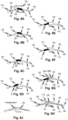
- the thin wing portion 51 comes into contact with the lower jaw 106 and with upper jaw 104 and pries them apart as shown in Fig. 7B . Because the jaws are biased against each other, they exert a force from opposed sides on the thin wing portion 51, keeping the winged needle 90 properly aligned with the front slot 109 for the entire traversal of the winged needle 90 through the front slot 109 and the rear slot 135.
- the lower jaw 106 is extended to the point where it underlies region where the finger is placed for removal of the winged needle 90. Comfort may further be increased by providing that there is a convex bevel 1401 at the forward end of the lower jaw as shown in Fig. 14B .
- the channel shaped upper and lower jaws form trusses that have reasonably good resistance to bending even if the walls are thin over at least a portion thereof.
- the upper jaw has higher depending walls and can tolerate a longer thin span indicated at 149.
- the lower wall having lower depending walls is reinforced by thickened region 140 further toward the front end of the needle guard 101 so that there is a shorter thin region 145.
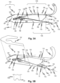
- the hinge arc in back experiences a torsional twisting moment about a vertical axis 133 which is harder to resist with the hollow structure especially with the presence of the opening 207 (See Fig. 4B ).
- the hinge portion 143 is reinforced by thickened walls.
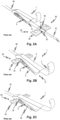
- the extended lower jaw 106 of the needle guard 101 permits the convenient placement of the front end 122 of the lower jaw under the needle hub 49 adjacent a needle puncture site 141 of a patient's body 131. This allows the positioning the finger shield 102 above the puncture site 141. This helps to ensure the hub (nub 54 or equivalent, if present) is, prior to drawing, positioned between the 122A side wall 114 edge leading portion 77 as indicated at 122A as indicated at 177, as shown in Fig. 3B .
- the finger shield 102 is extends from the front end 120 of upper jaw 104.
- the finger shield 102 may be integrally formed with the roof 115 of the upper jaw 104 or may be attached to the upper jaw 104 as a separate component.
- the finger shield 102 facilitates holding the needle guard 101 in position while the needle is drawn into it.
- the shield 102 has a thin portion 1022 and a thick portion 1021.
- the thick portion 1021 is thicker than the thin portion 1022, and is thus less flexible.
- the finger shield 102 This allows the finger shield 102 to maintain its shape so that it curls around a user's fingertip even when the user presses down into the curve of the finger shield 102 toward a gauze place above the cannula 52 puncture site. This helps to ensure the finger shield 102 continues to hook the finger of the user to help resist the traction forces applied to the needle guard 191 as the winged needle 90 is drawn into it.
- the finger shield 102 in an embodiment has a uniform thickness.
- the upper surface of finger shield 102 may have ribs akin to ribs 124 on hinge 107, though these ribs are not illustrated on finger shield 102 and only on hinge 107.
- the embodiment also has a fixed width of front slot 109 but as indicated above the embodiment may be modified to have the narrowing slot as in Fig. 7A .
- the present figures show specific details such as surfaces and transitions between surfaces that improve the usability of the needle guard 101. These details include the smooth flat roof 115, shape and relative size of the opening 207, and relative thickness of the thickened region 140.
- the drawings also show a to-scale embodiment. Note also that details of the drawing indicate aspects that are essential for molding in a three part dual action injection molding process as will be appreciated by those of skill in the art.
- the finger shield 102 has a uniform thickness but may also be non-uniform as described with reference to Figs. 5A and 5B .
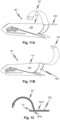
- a needle guard 501 is substantially as needle guard 101 in all respects except that as a molded piece 501' as released from the mold, the finger shield 102 and a safety flap 1023 are molded as shown in Fig. 11A . It will be confirmed by inspection that the shape of molded piece 501' permits the use of two mold halves and a core that can be drawn out of the internal space of the molded unit shown. Thus, as shown in Fig.
- the finger shield 102 is molded in the position shown above the roof 115 with a safety flap 1023 extending away from roof 115 in the direction from the rear of the molded piece 501' toward the front of the molded piece 501' to permit the withdrawal of a mold core in a single-shot, three-part molding operation.
- the finger shield 102 carrying the safety flap 1023 may be pivoted about a living hinge 1027B which is illustrated in Fig. 12 , to its final position for use shown in Fig. 11B .
- the safety flap 1023 may be thin enough to permit the winged needle 90 to pass by when it is drawn into the needle guard 101, and still overly an inserted needle to protect a user inserting a finger or other body part into the cavity 112, thus further reducing the possibility of an accidental puncture.
- the flexibility that permits the safety flap 1023 to permit the winged needle to pass may be provided (if the safety flap 1023 itself is thick or otherwise inflexible) or facilitated by means of a further living hinge 1027A.
- the safety flap 1023 may be coated with an absorbent material and/or may be made hydrophilic through a surface treatment such as electrical discharge machining. This will help prevent blood that may be in or on the cannula 52 from leaking out of the front opening of the needle guard 101.
- An absorbent material block can also be attached to the safety flap 1023, similar to the block 802 in Fig. 9 .
- the block 802 would be on the inner side of the safety flap 1023 and in position to absorb stray blood from the cannula 52.
- the safety flap 1023 covers the tip of a cannula in the stored position after it is fully retracted and locked so even if a body part were pushed into the front end of the needle guard 501, the safety flap 1023 isolates the body part from the tip of the cannula 52.
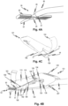
- the finger shield 102 can be folded and locked in engagement with the lower jaw 106 to block cavity 112, as shown in Figs. 13A-13C.
- Fig. 13A illustrates the needle guard 101 after the winged needle 90 has been fully pulled into the needle guard. The pointed end of the needle is pressed against roof 115 of the upper jaw 104. Though the needle is now safely stored, it is advantageous to further prevent a user, such as a child, from inserting a finger into the cavity 112.
- finger shield 102 has an opening that mates with the front end 122 of the lower jaw.
- Fig. 13B illustrates the finger shield 102 being bent down toward lower jaw 106
- Fig. 13C illustrates the final position where the finger shield 102 is mated to the lower jaw 106, closing off the cavity 112.
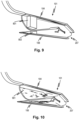
- Fig. 9 shows a cut-away view of needle guard 101 with a resilient block 801 and 802 placed inside the cavity 112.
- the block 801 may have two parts indicated at 801 and 802 and may be of foam or other material and may be absorbent, hydrophilic, or hydrophobic.
- the block parts 801 and 802 may be connected by a thin tearable sheet (not shown) to permit them to be stuffed into the front end of the needle guard 101 after molding in a single operation. Alternatively, they may be emplaced by a fixture that aligns them with respect to each other. They may be held in place by adhesive or locked by engagement features in the interior of the needle guard such as a roughened surface or pins or some other suitable mechanism.
- the space between the two block parts 801 and 802 allows the winged needle 90 to pass but helps to block blood or other fluid from escaping.
- the block parts 801 and 802 may have other suitable shapes that do not interfere with wings 50 when winged needle 90 is pulled through the needle guard. Block parts 801 and 802 may be of foam, gauze, or other material.
- Fig. 10 shows a cut-away view of another embodiment of needle guard 101 where cavity 112 has an inner surface 901.
- the inner surface 901 is the inner surface of side walls 113 and 114 and the inner surface of roof 115 and floor 125.
- the inner surface is coated with an absorbent coating or hydrophilic surface treatment.
- the inner surface 901 may be textured to provide a hydrophilic surface that attracts stray blood drops and causes them to cling to the inner surface of cavity 112 rather than falling out.
- the embodiment of Fig. 9 will be combined with the embodiment of Fig. 10 , where an absorbent coating is provided on inner surface 901 and absorbent material blocks 801 and 802 are provided in the cavity 112.
- the needle guard 101 is made of high density polyethylene (HDPE) which has thermal properties that can bias the upper jaw against the lower jaw as described above.
- HDPE has a flexural modulus of over 300 Mpa.
- the HDPE has a flexural modulus of over 1000 Mpa.
- the HDPE has a flexural modulus of at least 1200 Mpa.
- the high flexural modulus of HDPE increases the needle guard's resistance to twisting.
- HDPE use also facilitates sterilization because it is compatible with gamma irradiation sterilization.
- HDPE also provides a low coefficient of friction between the wings and the needle guard, making it easy to withdraw the needle into the needle guard with a smooth and continuous motion.
- Other suitable materials include polypropylene and low density polyethylene.
- An exemplary embodiment of the disclosed subject matter includes a needle set that has a needle guard ( 101 ) and a winged needle ( 90 ).
- the needle guard ( 101 ) has elongate upper and lower jaws ( 104 , 106 ) each defining a channel ( 109, 135 ) and joined at a hinge portion ( 143 ), each jaw having depending side walls ( 113 , 114 ) with elongate edges parallel to a longitudinal axis of each channel, each edge ( 108 , 110 ) of each jaw being aligned with and spaced from a respective edge of the other jaw defining elongate slots along the side walls.
- the winged needle has a cannula ( 52 ), a hub ( 49 ), and a pair of wings ( 53 ).
- a tube ( 60 ) is connected to the cannula ( 52 ) by the hub ( 49 ).
- the hinge ( 107 ) has an opening ( 207 ) into which the tube ( 60 ) is received.
- the side walls ( 113, 114 ) are spaced apart to permit the hub ( 49 ) to be received between the jaws ( 104, 106 ) with the wings ( 50, 51, 53 ) in the slots ( 109, 135 ).
- Each elongate slot has an open end opposite the hinge portion and the elongate slots progressively narrow to a first spacing that is narrower than a thickness of each wing portion ( 51 ) at a point thereof that is aligned with a respective pair of the edges, and thereafter expands linearly to a second spacing that is substantially equal to the thickness of each wing portion ( 51 ).
- the side walls ( 113, 114 ) are thicker at the hinge portion ( 143 ) than at the open end.
- a cross-section of a cylindrical space between the jaws ( 104 , 106 ) and in a plane perpendicular to the longitudinal axis is constant along a majority of a length of the needle guard, except for a vertical dimension thereof that diminishes progressively from a maximum dimension at the hinge portion ( 143 ) to a minimum dimension at the open end ( 120 , 122 ), the maximum and minimum dimensions differing by the difference between the first and second spacings.
- a cross-section of a cylindrical space between the jaws ( 104 , 106 ) and perpendicular to said longitudinal axis is uniform in a horizontal direction and progresses, in the vertical direction, from a maximum dimension at the hinge portion to a minimum dimension at the open end, the maximum and minimum dimensions differing by the difference between the first and second spacings.
- the first spacing may be zero.
- the jaws ( 104 , 106 ) define a space therebetween that has a negative draft.
- the negative draft allows a center mold piece to be removed from the space between the jaws after the needle guard 101 is manufactured.
- the magnitude of the negative draft is equal to the difference between the first and second spacings.
- the channels defined by the jaws ( 104 , 106 ) have C-shaped cross-sections.
- the forcing includes prying the cylindrical guard apart by urging the wings ( 50, 51, 53 ) into progressively narrowing entrances of the elongate slots ( 109 ).
- the interferingly engaging includes interferingly engaging steps in the surface of the wings ( 50, 51, 53 ) with the edges ( 134 , 136 ).
- the method may include positioning a lower portion ( 106 ) of the cylindrical guard underneath the winged needle ( 90 ) prior to said drawing.
- the preventing may include, prior to the forcing, guiding a central hub ( 49 ) of the winged needle ( 90 ) between barriers ( 114 ) on either side of said lower portion.
- the drawing may include drawing the wings ( 50, 51, 53 ) into expanded slot segments ( 138 ) of the elongate slots ( 109 , 135 ) where the width of the slots expands and thereafter, proceeding further, bends where an edge of each slot defines a deflectable portion ( 126 ), the drawing further causing the wings to be urged against the deflectable portion as both the deflectable portion and the wings deform, the expanded slot segments being sized such that tail ends of the wings move across the expanded slot segments without friction in an initial stage of passing the deflectable portion.
- the drawing may include drawing the wings ( 50, 51, 53 ) into expanded slot segments ( 138 ) of the elongate slots ( 109, 135 ) where the width of the slots expands and thereafter, proceeding further, bends where an edge of each slot defines a deflectable portion ( 126 ), the deflectable portion having hook shapes ( 127 ) over which a leading edge of the wings rides after it enters the expanded slot segments, drawing further causing the wings to be urged against the deflectable portion as both the deflectable portion and the wings deform in order to follow the elongate slots through the bends.
- a needle set includes a needle guard ( 101 ), a winged needle ( 90 ) with a cannula ( 52 ) that has a hub ( 49 ) with a pair of wings ( 50, 51, 53 ), and a tube ( 60 ) connected to the cannula by the hub.
- the needle guard has elongate upper and lower jaws ( 104, 106 ) each defining a channel and joined at a hinge portion ( 143 ), each jaw having depending side walls with elongate edges parallel to a longitudinal axis of each channel, each edge of each jaw being aligned with and spaced from a respective edge of the other jaw defining elongate slots ( 109, 135 ) along the side walls.
- the hinge has an opening 207 into which the tube ( 60 ) is received and the side walls are spaced apart to permit the hub ( 49 ) to be received between the jaws ( 104, 106 ) with the wings ( 50, 51, 53 ) in the slots ( 109, 135 ).
- the lower jaw ( 106 ) extends beyond the upper jaw ( 104 ).
- the lower jaw ( 106 ) is C-shaped at its distal end defining sloping barriers on each side thereof to permit the lower to jaw ( 106 ) to be positioned beneath the hub ( 49 ) while the cannula ( 52 ) is inserted in a patient.
- the lower jaw ( 106 ) has a rounded front edge.
- the drawing includes forcing effective to pry the cylindrical guard apart by urging the wings into progressively narrowing entrances of the elongate slots until the wings hold the slots open and the wings can slide therethrough.
- a needle set includes a winged needle ( 90 ) and a channel member ( 104 , 106 ) having a longitudinal axis.
- the winged needle includes a hub ( 49 ), a cannula ( 52 ), and wings ( 50, 51, 53 ).
- the channel further has sidewalls ( 113 , 114 ) with slots opposite each other and parallel to said axis.
- the slots are open at an open end of the channel member and closed at a hinge end of the channel member.
- Each slot has a first portion ( 109 ) beginning at the open end where it has a constant width or a width that increases linearly from the open end toward the hinge end.
- Each slot has a progressively narrowing entry at the open end leading to the first portion ( 109 ).
- the needle guard includes an upper jaw ( 104 ), a hinge ( 107 ), and a lower jaw ( 106 ).
- the upper jaw includes a roof ( 115 ), two opposed upper side walls ( 113 ) extending down from the roof, where each upper side wall includes an upper edge integral with the roof, a curved side edge at the front end, and a substantially straight bottom edge ( 108 ) abutting a bridge slot ( 138 ) at a rear end of the bottom edge.
- the upper jaw abuts the hinge ( 107 ), which in turn abuts the lower jaw ( 106 ).
- the upper edge of the upper side wall is substantially straight.
- the floor is substantially flat.
- the floor includes a front edge ( 122 ) that has a rounded shape.
- a finger shield extends from a front end of the roof of the upper jaw, the finger shield including a curved strip extending up from the front end of the roof.
- the finger shield ( 102 ) includes a thin portion ( 1022 ) immediately abutting the roof of the upper jaw, and a thick portion ( 1021 ) having a thickness greater than the thickness of the thin portion abutting the thin portion.
- the width of the finger shield ( 102 ) measured perpendicularly to the upper side wall is substantially same as the width of the roof ( 115 ) of the upper jaw.
- the finger shield ( 102 ) is configured to fold toward the lower jaw after the winged needle is pulled into the needle guard, to engage the lower jaw to close the front end of the needle guard.
- finger shield ( 102 ) also includes a safety flap ( 1023 ) extending from the roof toward the floor when the finger shield is pressed toward the lower jaw.
- the rear slot ( 135 ) of the hinge is bounded by a region of material having a first thickness that is smaller than the thickness of the thickened region of the hinge.
- the region of the material having the first thickness cools faster than the thickened region of the hinge when the needle guard is molded or cast. The difference in cooling time pulls the upper jaw ( 104 ) toward the lower jaw ( 106 ).
- the front slot ( 109 ) tapers from the front end of the needle guard toward the rear end of the needle guard.
- the latch ( 126 ) includes a barb ( 127 ) protruding from latch toward the bridge slot.
- the barb ( 127 ) forms a kind or a hockey-stick shape on the upper edge of the latch ( 126 ).
- a safety needle set in another exemplary embodiment disclosed above, includes a winged needle ( 90 ) having a hub ( 49 ) with wings ( 50, 51, 53 ) extending in opposite directions, a cannula ( 52 ) held in the center of the hub, and a tube ( 60 ) extending from the hub on a side opposite the needle.
- the safety needle set also includes a needle guard ( 101 ) according to any combination of the exemplary embodiments disclosed above.
- cylinder or “cylindrical” may refer to a hollow structure and is not limited to a structure with a circular cross-section.
- a hollow elongate prism or one elongate structure with an elliptical cross-section or piece-wise closed cross-section may be identified by the term "cylinder.”
- any of the embodiments may be modified by providing additional openings, for example the floor of the needle guards 101 may be opened (U-shaped) to permit a snap-on type of arrangement that allows the user to emplace the needle guard over a winged needle and tube set.
- needle sets including a needle guard, methods of guarding a needle using a needle guard and further needle guards are described.
- the needle guards described in the following are manufacturable using the inventive method.
- a needle set comprising: a needle guard having elongate upper and lower jaws each defining a channel and joined at a hinge portion, each jaw having depending side walls with elongate edges parallel to a longitudinal axis of each channel, each edge of each jaw being aligned with and spaced from a respective edge of the other jaw defining elongate slots along the side walls; a winged needle having a cannula, a hub with a pair of wings; a tube connected to the cannula by the hub; the hinge having an opening into which the tube is received; the side walls being spaced apart to permit the hub to be received between the jaws with the wings in the slots; each elongate slot having an open end opposite the hinge portion, the elongate slots progressively narrowing to a first spacing that is narrower than a thickness of each wing at a point thereof that is aligned with a respective pair of said edges, and thereafter expanding linearly to a second spacing that is substantially equal to said thickness.
- the forcing includes prying the cylindrical guard apart by urging the wings into progressively narrowing entrances of said elongate slots.
- the needle guard further comprising: a finger shield extending from a front end of the roof of the upper jaw, the finger shield including a curved strip extending up from the front end of the roof.
- the third part axis angle is such that the first and third part axes cross above the first and third parts, whereby they form a downward facing obtuse angle.
Landscapes
- Health & Medical Sciences (AREA)
- Life Sciences & Earth Sciences (AREA)
- Engineering & Computer Science (AREA)
- Public Health (AREA)
- Veterinary Medicine (AREA)
- Biomedical Technology (AREA)
- Heart & Thoracic Surgery (AREA)
- Hematology (AREA)
- Animal Behavior & Ethology (AREA)
- General Health & Medical Sciences (AREA)
- Biophysics (AREA)
- Anesthesiology (AREA)
- Physics & Mathematics (AREA)
- Pathology (AREA)
- Medical Informatics (AREA)
- Molecular Biology (AREA)
- Surgery (AREA)
- Vascular Medicine (AREA)
- Pulmonology (AREA)
- Environmental & Geological Engineering (AREA)
- Infusion, Injection, And Reservoir Apparatuses (AREA)
Claims (4)
- Ein Verfahren zur Herstellung eines Nadelschutzes (101, 501), aufweisend:Bereitstellen einer Form (210) mit einem Abschnitt (212), der ein Volumen definiert, wobei das Volumen ein Hohlzylinder mit ungleichmäßigen Wänden (113, 114) mit einem Paar von Schlitzen (109, 135) darin ist, wobei die Schlitze an einem Ende (120) offen und am anderen Ende (107) geschlossen sind, wobei das Paar von Schlitzen einen Hauptabschnitt mit konstanter Breite aufweist,wobei die ungleichmäßigen Wände an dem anderen Ende (107) dicker sind als an dem einen Ende (120),Füllen des Volumens mit Polymer,Freigeben eines Formteils (214) aus der Form (210),Kühlen des Formteils (214), das aus dem Füllen und Freigeben resultiert, so dass eine Breite des Paars von Schlitzen (109, 135) nach dem Kühlen ungleichmäßig ist,wobei der Zeitpunkt der Freigabe und das weitere Kühlen derart ist, dass die eine Seite des Formteilabschnitts, die zu dem anderen Ende (107) korrespondiert, ungleichmäßig abkühlt, so dass die Breiten ungleichmäßig werden,wobei Schlitze (109, 135) des Formteils (214) an Abschnitten, die zu dem einen Ende (120) korrespondieren, schmaler sind undwobei zumindest ein Abschnitt des Formteils (214) bei der Freigabe noch in einem plastischen Zustand ist unddas Kühlen einen negativen Luftzug im Inneren des Hohlzylinders erzeugt.
- Das Verfahren gemäß Anspruch 1, wobei das Formteil ist:
ein Nadelschutz (101) zum Schutz eines Benutzers vor einer Nadel, die von einem vorderen Ende des Nadelschutzes zu einem hinteren Ende des Nadelschutzes gezogen wird, wobei der Nadelschutz aufweist:eine obere Backe (104), die aufweistein Dach (115),zwei entgegengesetzte obere Seitenwände (113), die sich von dem Dach nach unten erstrecken, wobei jede obere Seitenwand aufweisteinen oberen Rand, der von dem Dach (115) ausgeht,einen gekrümmten Seitenrand am vorderen Ende undeinen im Wesentlichen geraden unteren Rand (108), der an einem hinteren Ende des unteren Rands (108) an einen Brückenschlitz (138) angrenzt, wobei die obere Backe an ein Scharnier (107) angrenzt,wobei das Scharnier (107) an die obere Backe (104) und eine untere Backe (106) angrenzt, wobei das Scharnier (107) einen oberen Scharnierrand (134) und einen unteren Scharnierrand (136) aufweist, die einen hinteren Schlitz (135) definieren, wobei der Brückenschlitz (138) über einen Punkt vorsteht, an dem sich eine Verlängerung des unteren Rands (108) und eine Verlängerung des oberen Scharnierrands (134) schneiden würden, undwobei die untere Backe (106) an das Scharnier (107) angrenzt und einen Boden (125),zwei entgegengesetzte untere Seitenwände (114), die sich von dem Boden (125) in Richtung der oberen Backe (104) nach oben erstrecken, wobei jede untere Seitenwand (114) einen von dem Boden ausgehenden unteren Rand aufweist,einen oberen Rand (110), der dem unteren Rand (108) der oberen Seitenwand zugewandt ist und sich in Richtung des vorderen Endes erstreckt, um auf den unteren Rand der unteren Seitenwand zu treffen, wobei der obere Rand der unteren Seitenwand und der untere Rand der oberen Seitenwand einen vorderen Schlitz (109) definieren, undeine Zunge (126) aufweist, die sich von der unteren Seitenwand (114) entgegengesetzt zum Brückenschlitz (138) erstreckt, wobeider vordere Schlitz (109) eine Hohlraumöffnung (112) am vorderen Ende des Nadelschutzes (101) definiert,der vordere Schlitz (109) mit dem hinteren Schlitz (135) verbunden ist,die Zunge (126) einen Spitzenabschnitt (137) hat, der zusammen mit dem Brückenschlitz (138) einen S-förmigen Pfad definiert, durch den eine geflügelte Nadel von dem vorderen Schlitz (109) zu dem hinteren Schlitz (135) hindurchtritt, und der Spitzenabschnitt (137) die geflügelte Nadel daran hindert, aus dem hinteren Schlitz (135) entlang des S-förmigen Pfads herausgezogen zu werden. - Das Verfahren gemäß Anspruch 2, wobei der vordere Schlitz (109) eine konstante Breite hat.
- Das Verfahren gemäß Anspruch 2, wobei sich der vordere Schlitz (109) vom hinteren Ende des Nadelschutzes zum vorderen Ende des Nadelschutzes hin verjüngt.
Applications Claiming Priority (3)
| Application Number | Priority Date | Filing Date | Title |
|---|---|---|---|
| US201562202792P | 2015-08-08 | 2015-08-08 | |
| PCT/US2016/045885 WO2017027413A1 (en) | 2015-08-08 | 2016-08-05 | Needle guard |
| EP16835717.6A EP3331590B1 (de) | 2015-08-08 | 2016-08-05 | Nadelschutz |
Related Parent Applications (1)
| Application Number | Title | Priority Date | Filing Date |
|---|---|---|---|
| EP16835717.6A Division EP3331590B1 (de) | 2015-08-08 | 2016-08-05 | Nadelschutz |
Publications (2)
| Publication Number | Publication Date |
|---|---|
| EP3777922A1 EP3777922A1 (de) | 2021-02-17 |
| EP3777922B1 true EP3777922B1 (de) | 2024-07-10 |
Family
ID=57984102
Family Applications (2)
| Application Number | Title | Priority Date | Filing Date |
|---|---|---|---|
| EP20199209.6A Active EP3777922B1 (de) | 2015-08-08 | 2016-08-05 | Verfahren zum herstellen eines nadelschutzes |
| EP16835717.6A Active EP3331590B1 (de) | 2015-08-08 | 2016-08-05 | Nadelschutz |
Family Applications After (1)
| Application Number | Title | Priority Date | Filing Date |
|---|---|---|---|
| EP16835717.6A Active EP3331590B1 (de) | 2015-08-08 | 2016-08-05 | Nadelschutz |
Country Status (7)
| Country | Link |
|---|---|
| US (3) | US11305059B2 (de) |
| EP (2) | EP3777922B1 (de) |
| JP (1) | JP3220736U (de) |
| CN (1) | CN209221155U (de) |
| CA (1) | CA2995107C (de) |
| MX (1) | MX2021009948A (de) |
| WO (1) | WO2017027413A1 (de) |
Families Citing this family (3)
| Publication number | Priority date | Publication date | Assignee | Title |
|---|---|---|---|---|
| CN112292079B (zh) * | 2018-05-01 | 2024-05-28 | 贝克顿·迪金森公司 | 挤压致动的血液收集套件 |
| US12458780B2 (en) * | 2019-12-18 | 2025-11-04 | Becton, Dickinson And Company | Inhibiting fluid leakage and splatter in catheter devices and systems |
| CN111481776B (zh) * | 2020-05-07 | 2021-03-30 | 普昂(杭州)医疗科技有限公司 | 针装置及其保护结构和保护方法 |
Family Cites Families (13)
| Publication number | Priority date | Publication date | Assignee | Title |
|---|---|---|---|---|
| WO1990003196A1 (en) | 1988-09-30 | 1990-04-05 | Utterberg David S | Guarded winged needle assembly |
| US5562637A (en) | 1994-07-15 | 1996-10-08 | Utterberg; David S. | Needle protector sheath |
| US5704924A (en) | 1996-01-11 | 1998-01-06 | Medisystems Technology Corporation | Easy use needle protector sheath |
| US5772638A (en) | 1996-09-17 | 1998-06-30 | Medisystems Technology Corporation | Protector for needle |
| US5921969A (en) * | 1996-04-22 | 1999-07-13 | Vallelunga; Anthony J. | Apparatus for shielding a butterfly needle |
| JP2000246748A (ja) * | 1999-03-04 | 2000-09-12 | Toyoda Iron Works Co Ltd | 樹脂成形品の成形方法 |
| AU2001294191C1 (en) | 2000-10-06 | 2005-11-24 | Jms Co., Ltd | Wing retraction type mis-piercing preventer and winged needle having the mis-piercing preventer |
| DE602004018699D1 (de) * | 2003-03-20 | 2009-02-12 | Nipro Corp | Schutzkappe für Nadel mit Flügeln |
| US7591804B2 (en) | 2006-04-20 | 2009-09-22 | Dsu Medical Corporation | Short winged needle and guard |
| PL2593159T3 (pl) | 2010-07-15 | 2018-03-30 | Mddp, Llc | Urządzenie do wlewów i.v. lub pobierania krwi |
| US9151459B2 (en) * | 2011-10-11 | 2015-10-06 | Sabic Global Technologies B.V. | Mounting structure for a headlamp reflector |
| US10350366B2 (en) | 2013-02-01 | 2019-07-16 | Nxstage Medical, Inc. | Safe cannulation devices, methods, and systems |
| US20180360364A1 (en) | 2015-06-26 | 2018-12-20 | Chris Whelan | Needle Guard |
-
2016
- 2016-08-05 EP EP20199209.6A patent/EP3777922B1/de active Active
- 2016-08-05 JP JP2018600016U patent/JP3220736U/ja not_active Expired - Lifetime
- 2016-08-05 CA CA2995107A patent/CA2995107C/en active Active
- 2016-08-05 WO PCT/US2016/045885 patent/WO2017027413A1/en not_active Ceased
- 2016-08-05 EP EP16835717.6A patent/EP3331590B1/de active Active
- 2016-08-05 CN CN201690001146.0U patent/CN209221155U/zh not_active Expired - Lifetime
- 2016-08-05 US US15/749,965 patent/US11305059B2/en active Active
-
2018
- 2018-02-07 MX MX2021009948A patent/MX2021009948A/es unknown
-
2022
- 2022-04-05 US US17/713,870 patent/US11904137B2/en active Active
-
2024
- 2024-01-12 US US18/411,444 patent/US12364811B2/en active Active
Also Published As
| Publication number | Publication date |
|---|---|
| US20220288307A1 (en) | 2022-09-15 |
| CN209221155U (zh) | 2019-08-09 |
| CA2995107C (en) | 2021-11-16 |
| US11904137B2 (en) | 2024-02-20 |
| US20240139413A1 (en) | 2024-05-02 |
| EP3331590A4 (de) | 2019-02-27 |
| US11305059B2 (en) | 2022-04-19 |
| WO2017027413A1 (en) | 2017-02-16 |
| EP3331590B1 (de) | 2020-10-21 |
| US12364811B2 (en) | 2025-07-22 |
| JP3220736U (ja) | 2019-04-04 |
| US20180221592A1 (en) | 2018-08-09 |
| EP3331590A1 (de) | 2018-06-13 |
| CA2995107A1 (en) | 2017-02-16 |
| EP3777922A1 (de) | 2021-02-17 |
| MX2021009948A (es) | 2021-09-21 |
Similar Documents
| Publication | Publication Date | Title |
|---|---|---|
| US12364811B2 (en) | Needle guard | |
| JP3843414B2 (ja) | 針保護鞘 | |
| US20210275782A1 (en) | Low profile passive protector for an i.v. catheter | |
| JP2023053396A (ja) | カテーテル組立体 | |
| US5921969A (en) | Apparatus for shielding a butterfly needle | |
| US20120143151A1 (en) | Needle shield and a winged needle assembly | |
| EP1980284A1 (de) | Medizinische nadelvorrichtung | |
| JPH07185002A (ja) | 針保護装置 | |
| EP0534000A2 (de) | Vorrichtung zum Schutz gegen versehentliches Stechen durch mit Flügeln versehene Kanülen | |
| WO2005110225A1 (ja) | ランセットアッセンブリ | |
| JP2010162410A (ja) | 安全針アセンブリ | |
| WO2011146772A1 (en) | Safety needle system operable with a medical device | |
| KR20110116237A (ko) | 의료용 바늘 장치 | |
| RU2562107C2 (ru) | Игла с защитным устройством | |
| JP4182756B2 (ja) | 翼引込み式誤穿刺防止具、および該誤穿刺防止具を備えた翼付き針 | |
| EP1159983B1 (de) | Klemme für Nadel mit Flügeln | |
| JP2009538160A (ja) | フーバー針アセンブリ及び使用方法 | |
| US7367962B2 (en) | Winged medical needle device | |
| CN117881452A (zh) | 带有一体化分配器的导管和相关的制造方法 |
Legal Events
| Date | Code | Title | Description |
|---|---|---|---|
| PUAI | Public reference made under article 153(3) epc to a published international application that has entered the european phase |
Free format text: ORIGINAL CODE: 0009012 |
|
| STAA | Information on the status of an ep patent application or granted ep patent |
Free format text: STATUS: THE APPLICATION HAS BEEN PUBLISHED |
|
| AC | Divisional application: reference to earlier application |
Ref document number: 3331590 Country of ref document: EP Kind code of ref document: P |
|
| AK | Designated contracting states |
Kind code of ref document: A1 Designated state(s): AL AT BE BG CH CY CZ DE DK EE ES FI FR GB GR HR HU IE IS IT LI LT LU LV MC MK MT NL NO PL PT RO RS SE SI SK SM TR |
|
| STAA | Information on the status of an ep patent application or granted ep patent |
Free format text: STATUS: REQUEST FOR EXAMINATION WAS MADE |
|
| 17P | Request for examination filed |
Effective date: 20210816 |
|
| RBV | Designated contracting states (corrected) |
Designated state(s): AL AT BE BG CH CY CZ DE DK EE ES FI FR GB GR HR HU IE IS IT LI LT LU LV MC MK MT NL NO PL PT RO RS SE SI SK SM TR |
|
| GRAP | Despatch of communication of intention to grant a patent |
Free format text: ORIGINAL CODE: EPIDOSNIGR1 |
|
| STAA | Information on the status of an ep patent application or granted ep patent |
Free format text: STATUS: GRANT OF PATENT IS INTENDED |
|
| INTG | Intention to grant announced |
Effective date: 20240207 |
|
| GRAS | Grant fee paid |
Free format text: ORIGINAL CODE: EPIDOSNIGR3 |
|
| GRAA | (expected) grant |
Free format text: ORIGINAL CODE: 0009210 |
|
| STAA | Information on the status of an ep patent application or granted ep patent |
Free format text: STATUS: THE PATENT HAS BEEN GRANTED |
|
| P01 | Opt-out of the competence of the unified patent court (upc) registered |
Effective date: 20240529 |
|
| AC | Divisional application: reference to earlier application |
Ref document number: 3331590 Country of ref document: EP Kind code of ref document: P |
|
| AK | Designated contracting states |
Kind code of ref document: B1 Designated state(s): AL AT BE BG CH CY CZ DE DK EE ES FI FR GB GR HR HU IE IS IT LI LT LU LV MC MK MT NL NO PL PT RO RS SE SI SK SM TR |
|
| REG | Reference to a national code |
Ref country code: CH Ref legal event code: EP |
|
| REG | Reference to a national code |
Ref country code: DE Ref legal event code: R096 Ref document number: 602016088404 Country of ref document: DE |
|
| REG | Reference to a national code |
Ref country code: LT Ref legal event code: MG9D |
|
| REG | Reference to a national code |
Ref country code: NL Ref legal event code: MP Effective date: 20240710 |
|
| PG25 | Lapsed in a contracting state [announced via postgrant information from national office to epo] |
Ref country code: PT Free format text: LAPSE BECAUSE OF FAILURE TO SUBMIT A TRANSLATION OF THE DESCRIPTION OR TO PAY THE FEE WITHIN THE PRESCRIBED TIME-LIMIT Effective date: 20241111 |
|
| REG | Reference to a national code |
Ref country code: AT Ref legal event code: MK05 Ref document number: 1701491 Country of ref document: AT Kind code of ref document: T Effective date: 20240710 |
|
| PG25 | Lapsed in a contracting state [announced via postgrant information from national office to epo] |
Ref country code: NL Free format text: LAPSE BECAUSE OF FAILURE TO SUBMIT A TRANSLATION OF THE DESCRIPTION OR TO PAY THE FEE WITHIN THE PRESCRIBED TIME-LIMIT Effective date: 20240710 |
|
| PG25 | Lapsed in a contracting state [announced via postgrant information from national office to epo] |
Ref country code: PT Free format text: LAPSE BECAUSE OF FAILURE TO SUBMIT A TRANSLATION OF THE DESCRIPTION OR TO PAY THE FEE WITHIN THE PRESCRIBED TIME-LIMIT Effective date: 20241111 Ref country code: NL Free format text: LAPSE BECAUSE OF FAILURE TO SUBMIT A TRANSLATION OF THE DESCRIPTION OR TO PAY THE FEE WITHIN THE PRESCRIBED TIME-LIMIT Effective date: 20240710 |
|
| PG25 | Lapsed in a contracting state [announced via postgrant information from national office to epo] |
Ref country code: NO Free format text: LAPSE BECAUSE OF FAILURE TO SUBMIT A TRANSLATION OF THE DESCRIPTION OR TO PAY THE FEE WITHIN THE PRESCRIBED TIME-LIMIT Effective date: 20241010 |
|
| PG25 | Lapsed in a contracting state [announced via postgrant information from national office to epo] |
Ref country code: FI Free format text: LAPSE BECAUSE OF FAILURE TO SUBMIT A TRANSLATION OF THE DESCRIPTION OR TO PAY THE FEE WITHIN THE PRESCRIBED TIME-LIMIT Effective date: 20240710 Ref country code: PL Free format text: LAPSE BECAUSE OF FAILURE TO SUBMIT A TRANSLATION OF THE DESCRIPTION OR TO PAY THE FEE WITHIN THE PRESCRIBED TIME-LIMIT Effective date: 20240710 Ref country code: GR Free format text: LAPSE BECAUSE OF FAILURE TO SUBMIT A TRANSLATION OF THE DESCRIPTION OR TO PAY THE FEE WITHIN THE PRESCRIBED TIME-LIMIT Effective date: 20241011 |
|
| PG25 | Lapsed in a contracting state [announced via postgrant information from national office to epo] |
Ref country code: BG Free format text: LAPSE BECAUSE OF FAILURE TO SUBMIT A TRANSLATION OF THE DESCRIPTION OR TO PAY THE FEE WITHIN THE PRESCRIBED TIME-LIMIT Effective date: 20240710 |
|
| PG25 | Lapsed in a contracting state [announced via postgrant information from national office to epo] |
Ref country code: LV Free format text: LAPSE BECAUSE OF FAILURE TO SUBMIT A TRANSLATION OF THE DESCRIPTION OR TO PAY THE FEE WITHIN THE PRESCRIBED TIME-LIMIT Effective date: 20240710 |
|
| PG25 | Lapsed in a contracting state [announced via postgrant information from national office to epo] |
Ref country code: IS Free format text: LAPSE BECAUSE OF FAILURE TO SUBMIT A TRANSLATION OF THE DESCRIPTION OR TO PAY THE FEE WITHIN THE PRESCRIBED TIME-LIMIT Effective date: 20241110 Ref country code: AT Free format text: LAPSE BECAUSE OF FAILURE TO SUBMIT A TRANSLATION OF THE DESCRIPTION OR TO PAY THE FEE WITHIN THE PRESCRIBED TIME-LIMIT Effective date: 20240710 |
|
| PG25 | Lapsed in a contracting state [announced via postgrant information from national office to epo] |
Ref country code: HR Free format text: LAPSE BECAUSE OF FAILURE TO SUBMIT A TRANSLATION OF THE DESCRIPTION OR TO PAY THE FEE WITHIN THE PRESCRIBED TIME-LIMIT Effective date: 20240710 |
|
| PG25 | Lapsed in a contracting state [announced via postgrant information from national office to epo] |
Ref country code: ES Free format text: LAPSE BECAUSE OF FAILURE TO SUBMIT A TRANSLATION OF THE DESCRIPTION OR TO PAY THE FEE WITHIN THE PRESCRIBED TIME-LIMIT Effective date: 20240710 Ref country code: RS Free format text: LAPSE BECAUSE OF FAILURE TO SUBMIT A TRANSLATION OF THE DESCRIPTION OR TO PAY THE FEE WITHIN THE PRESCRIBED TIME-LIMIT Effective date: 20241010 |
|
| PG25 | Lapsed in a contracting state [announced via postgrant information from national office to epo] |
Ref country code: RS Free format text: LAPSE BECAUSE OF FAILURE TO SUBMIT A TRANSLATION OF THE DESCRIPTION OR TO PAY THE FEE WITHIN THE PRESCRIBED TIME-LIMIT Effective date: 20241010 Ref country code: PL Free format text: LAPSE BECAUSE OF FAILURE TO SUBMIT A TRANSLATION OF THE DESCRIPTION OR TO PAY THE FEE WITHIN THE PRESCRIBED TIME-LIMIT Effective date: 20240710 Ref country code: NO Free format text: LAPSE BECAUSE OF FAILURE TO SUBMIT A TRANSLATION OF THE DESCRIPTION OR TO PAY THE FEE WITHIN THE PRESCRIBED TIME-LIMIT Effective date: 20241010 Ref country code: LV Free format text: LAPSE BECAUSE OF FAILURE TO SUBMIT A TRANSLATION OF THE DESCRIPTION OR TO PAY THE FEE WITHIN THE PRESCRIBED TIME-LIMIT Effective date: 20240710 Ref country code: IS Free format text: LAPSE BECAUSE OF FAILURE TO SUBMIT A TRANSLATION OF THE DESCRIPTION OR TO PAY THE FEE WITHIN THE PRESCRIBED TIME-LIMIT Effective date: 20241110 Ref country code: HR Free format text: LAPSE BECAUSE OF FAILURE TO SUBMIT A TRANSLATION OF THE DESCRIPTION OR TO PAY THE FEE WITHIN THE PRESCRIBED TIME-LIMIT Effective date: 20240710 Ref country code: GR Free format text: LAPSE BECAUSE OF FAILURE TO SUBMIT A TRANSLATION OF THE DESCRIPTION OR TO PAY THE FEE WITHIN THE PRESCRIBED TIME-LIMIT Effective date: 20241011 Ref country code: FI Free format text: LAPSE BECAUSE OF FAILURE TO SUBMIT A TRANSLATION OF THE DESCRIPTION OR TO PAY THE FEE WITHIN THE PRESCRIBED TIME-LIMIT Effective date: 20240710 Ref country code: ES Free format text: LAPSE BECAUSE OF FAILURE TO SUBMIT A TRANSLATION OF THE DESCRIPTION OR TO PAY THE FEE WITHIN THE PRESCRIBED TIME-LIMIT Effective date: 20240710 Ref country code: BG Free format text: LAPSE BECAUSE OF FAILURE TO SUBMIT A TRANSLATION OF THE DESCRIPTION OR TO PAY THE FEE WITHIN THE PRESCRIBED TIME-LIMIT Effective date: 20240710 Ref country code: AT Free format text: LAPSE BECAUSE OF FAILURE TO SUBMIT A TRANSLATION OF THE DESCRIPTION OR TO PAY THE FEE WITHIN THE PRESCRIBED TIME-LIMIT Effective date: 20240710 |
|
| REG | Reference to a national code |
Ref country code: CH Ref legal event code: PL |
|
| REG | Reference to a national code |
Ref country code: DE Ref legal event code: R097 Ref document number: 602016088404 Country of ref document: DE |
|
| PG25 | Lapsed in a contracting state [announced via postgrant information from national office to epo] |
Ref country code: RO Free format text: LAPSE BECAUSE OF FAILURE TO SUBMIT A TRANSLATION OF THE DESCRIPTION OR TO PAY THE FEE WITHIN THE PRESCRIBED TIME-LIMIT Effective date: 20240710 Ref country code: SM Free format text: LAPSE BECAUSE OF FAILURE TO SUBMIT A TRANSLATION OF THE DESCRIPTION OR TO PAY THE FEE WITHIN THE PRESCRIBED TIME-LIMIT Effective date: 20240710 Ref country code: DK Free format text: LAPSE BECAUSE OF FAILURE TO SUBMIT A TRANSLATION OF THE DESCRIPTION OR TO PAY THE FEE WITHIN THE PRESCRIBED TIME-LIMIT Effective date: 20240710 |
|
| PG25 | Lapsed in a contracting state [announced via postgrant information from national office to epo] |
Ref country code: LU Free format text: LAPSE BECAUSE OF NON-PAYMENT OF DUE FEES Effective date: 20240805 |
|
| PG25 | Lapsed in a contracting state [announced via postgrant information from national office to epo] |
Ref country code: CH Free format text: LAPSE BECAUSE OF NON-PAYMENT OF DUE FEES Effective date: 20240831 Ref country code: EE Free format text: LAPSE BECAUSE OF FAILURE TO SUBMIT A TRANSLATION OF THE DESCRIPTION OR TO PAY THE FEE WITHIN THE PRESCRIBED TIME-LIMIT Effective date: 20240710 Ref country code: MC Free format text: LAPSE BECAUSE OF FAILURE TO SUBMIT A TRANSLATION OF THE DESCRIPTION OR TO PAY THE FEE WITHIN THE PRESCRIBED TIME-LIMIT Effective date: 20240710 |
|
| PG25 | Lapsed in a contracting state [announced via postgrant information from national office to epo] |
Ref country code: CZ Free format text: LAPSE BECAUSE OF FAILURE TO SUBMIT A TRANSLATION OF THE DESCRIPTION OR TO PAY THE FEE WITHIN THE PRESCRIBED TIME-LIMIT Effective date: 20240710 |
|
| PG25 | Lapsed in a contracting state [announced via postgrant information from national office to epo] |
Ref country code: SK Free format text: LAPSE BECAUSE OF FAILURE TO SUBMIT A TRANSLATION OF THE DESCRIPTION OR TO PAY THE FEE WITHIN THE PRESCRIBED TIME-LIMIT Effective date: 20240710 |
|
| PLBE | No opposition filed within time limit |
Free format text: ORIGINAL CODE: 0009261 |
|
| STAA | Information on the status of an ep patent application or granted ep patent |
Free format text: STATUS: NO OPPOSITION FILED WITHIN TIME LIMIT |
|
| 26N | No opposition filed |
Effective date: 20250411 |
|
| REG | Reference to a national code |
Ref country code: BE Ref legal event code: MM Effective date: 20240831 |
|
| PG25 | Lapsed in a contracting state [announced via postgrant information from national office to epo] |
Ref country code: BE Free format text: LAPSE BECAUSE OF NON-PAYMENT OF DUE FEES Effective date: 20240831 |
|
| PG25 | Lapsed in a contracting state [announced via postgrant information from national office to epo] |
Ref country code: IE Free format text: LAPSE BECAUSE OF NON-PAYMENT OF DUE FEES Effective date: 20240805 |
|
| PG25 | Lapsed in a contracting state [announced via postgrant information from national office to epo] |
Ref country code: SE Free format text: LAPSE BECAUSE OF FAILURE TO SUBMIT A TRANSLATION OF THE DESCRIPTION OR TO PAY THE FEE WITHIN THE PRESCRIBED TIME-LIMIT Effective date: 20240710 |
|
| PGFP | Annual fee paid to national office [announced via postgrant information from national office to epo] |
Ref country code: DE Payment date: 20250724 Year of fee payment: 10 |
|
| PGFP | Annual fee paid to national office [announced via postgrant information from national office to epo] |
Ref country code: IT Payment date: 20250723 Year of fee payment: 10 |
|
| PGFP | Annual fee paid to national office [announced via postgrant information from national office to epo] |
Ref country code: GB Payment date: 20250724 Year of fee payment: 10 |
|
| PGFP | Annual fee paid to national office [announced via postgrant information from national office to epo] |
Ref country code: FR Payment date: 20250723 Year of fee payment: 10 |
|
| PG25 | Lapsed in a contracting state [announced via postgrant information from national office to epo] |
Ref country code: CY Free format text: LAPSE BECAUSE OF FAILURE TO SUBMIT A TRANSLATION OF THE DESCRIPTION OR TO PAY THE FEE WITHIN THE PRESCRIBED TIME-LIMIT; INVALID AB INITIO Effective date: 20160805 |
|
| PG25 | Lapsed in a contracting state [announced via postgrant information from national office to epo] |
Ref country code: HU Free format text: LAPSE BECAUSE OF FAILURE TO SUBMIT A TRANSLATION OF THE DESCRIPTION OR TO PAY THE FEE WITHIN THE PRESCRIBED TIME-LIMIT; INVALID AB INITIO Effective date: 20160805 |
|
| PG25 | Lapsed in a contracting state [announced via postgrant information from national office to epo] |
Ref country code: TR Free format text: LAPSE BECAUSE OF FAILURE TO SUBMIT A TRANSLATION OF THE DESCRIPTION OR TO PAY THE FEE WITHIN THE PRESCRIBED TIME-LIMIT Effective date: 20240710 |
|
| PG25 | Lapsed in a contracting state [announced via postgrant information from national office to epo] |
Ref country code: SI Free format text: LAPSE BECAUSE OF FAILURE TO SUBMIT A TRANSLATION OF THE DESCRIPTION OR TO PAY THE FEE WITHIN THE PRESCRIBED TIME-LIMIT Effective date: 20240710 |
|
| PG25 | Lapsed in a contracting state [announced via postgrant information from national office to epo] |
Ref country code: LT Free format text: LAPSE BECAUSE OF FAILURE TO SUBMIT A TRANSLATION OF THE DESCRIPTION OR TO PAY THE FEE WITHIN THE PRESCRIBED TIME-LIMIT Effective date: 20240710 |