EP3776772B1 - Bande de séparation pour une chaîne porte-câbles - Google Patents
Bande de séparation pour une chaîne porte-câbles Download PDFInfo
- Publication number
- EP3776772B1 EP3776772B1 EP19714197.1A EP19714197A EP3776772B1 EP 3776772 B1 EP3776772 B1 EP 3776772B1 EP 19714197 A EP19714197 A EP 19714197A EP 3776772 B1 EP3776772 B1 EP 3776772B1
- Authority
- EP
- European Patent Office
- Prior art keywords
- tongue element
- recess
- separator
- insertion opening
- separator according
- Prior art date
- Legal status (The legal status is an assumption and is not a legal conclusion. Google has not performed a legal analysis and makes no representation as to the accuracy of the status listed.)
- Active
Links
- 238000003780 insertion Methods 0.000 claims description 46
- 230000037431 insertion Effects 0.000 claims description 46
- 230000005540 biological transmission Effects 0.000 description 4
- 239000000463 material Substances 0.000 description 4
- 238000010276 construction Methods 0.000 description 2
- 238000006073 displacement reaction Methods 0.000 description 2
- 238000001746 injection moulding Methods 0.000 description 2
- 238000009434 installation Methods 0.000 description 2
- 238000005452 bending Methods 0.000 description 1
- 230000005489 elastic deformation Effects 0.000 description 1
- 238000005516 engineering process Methods 0.000 description 1
- 238000012423 maintenance Methods 0.000 description 1
Images

Classifications
-
- H—ELECTRICITY
- H02—GENERATION; CONVERSION OR DISTRIBUTION OF ELECTRIC POWER
- H02G—INSTALLATION OF ELECTRIC CABLES OR LINES, OR OF COMBINED OPTICAL AND ELECTRIC CABLES OR LINES
- H02G11/00—Arrangements of electric cables or lines between relatively-movable parts
- H02G11/006—Arrangements of electric cables or lines between relatively-movable parts using extensible carrier for the cable, e.g. self-coiling spring
-
- F—MECHANICAL ENGINEERING; LIGHTING; HEATING; WEAPONS; BLASTING
- F16—ENGINEERING ELEMENTS AND UNITS; GENERAL MEASURES FOR PRODUCING AND MAINTAINING EFFECTIVE FUNCTIONING OF MACHINES OR INSTALLATIONS; THERMAL INSULATION IN GENERAL
- F16G—BELTS, CABLES, OR ROPES, PREDOMINANTLY USED FOR DRIVING PURPOSES; CHAINS; FITTINGS PREDOMINANTLY USED THEREFOR
- F16G13/00—Chains
- F16G13/12—Hauling- or hoisting-chains so called ornamental chains
- F16G13/16—Hauling- or hoisting-chains so called ornamental chains with arrangements for holding electric cables, hoses, or the like
-
- H—ELECTRICITY
- H02—GENERATION; CONVERSION OR DISTRIBUTION OF ELECTRIC POWER
- H02G—INSTALLATION OF ELECTRIC CABLES OR LINES, OR OF COMBINED OPTICAL AND ELECTRIC CABLES OR LINES
- H02G3/00—Installations of electric cables or lines or protective tubing therefor in or on buildings, equivalent structures or vehicles
- H02G3/02—Details
- H02G3/04—Protective tubing or conduits, e.g. cable ladders or cable troughs
- H02G3/0462—Tubings, i.e. having a closed section
- H02G3/0475—Tubings, i.e. having a closed section formed by a succession of articulated units
Definitions
- the invention relates to a divider for a power transmission chain consisting of chain links which are pivotably connected to one another and which have two side plates which are connected to one another by two crosspieces in at least some chain links and define a guide channel for cables, in which dividers can be arranged between the crosspieces and on at least one of the crossbars can be locked, and plate-like shelves can be arranged substantially perpendicular to the dividers.
- the divider has at least one, usually several recesses, in each of which a shelf can be held and with a continuous, rigid support area at one lateral end of each recess and an insertion opening connected to the respective recess at the opposite lateral end for inserting a shelf are provided and wherein the insertion openings are each provided with a resilient tongue element for partially closing the respective insertion opening and for holding the respective shelf used.
- Cable drag chains are used to reliably and safely guide flexible supply lines that connect two connection points that can move relative to one another.
- the invention also relates to an energy transmission chain equipped with dividers.
- the invention is based on the object of further optimizing the mounting of the shelves in the divider and in particular of facilitating or accelerating the installation and removal of the shelves.
- this object is achieved by a divider according to claim 1 or an energy guiding chain according to claim 12.
- the object is already achieved in that the resilient tongue element extends essentially from the insertion opening to the opposite rigid support area of the separating web, that one end of the tongue element is connected to the edge of the insertion opening and the other end to the support area and that on the side of the tongue element that faces away from the recess, there is a free space into which the resilient tongue element can deviate elastically when inserting and removing the respective shelf.
- a core aspect of the invention thus lies in the special design of at least one resilient tongue element of the separating web, with which a reliable holding of the shelves can be achieved despite simplified installation and removal of the shelves.
- the support area is rigid in relation to the main plane of the separating web, in particular designed to be rigid, specifically so that it does not experience any bending as intended when inserting and removing a shelf.
- This can be achieved in particular by suitable dimensioning, in that the support area has a sufficient material thickness adjoining the recess(es), which is, for example, several times greater than the material thickness of the tongue element(s) that is or are flexible as intended.
- the separating web is preferably made of plastic. This has the advantage that the separating web can be designed as a one-piece part and can be produced inexpensively, for example using injection molding technology. In addition, the desired elastic deformability of the tongue element(s) can be inherently achieved by suitable dimensioning.
- the elastically deformable tongue element can also be molded onto the separating web in such a way that one end of the tongue element is integrally molded onto the edge of the insertion opening and the other end is also integrally molded onto the support area.
- the boundary wall of the recess opposite the resilient tongue element is expediently adapted to the outer contour of the panel-shaped shelf to be inserted, so that it can be firmly anchored in the separating web in a stable alignment.
- the resilient tongue element is preferably arranged along the longitudinal side, e.g. above or below, of the shelf to be inserted.
- the resilient tongue element preferably has a protruding nose on the side facing the recess, which serves to improve the seat of the compartment base in the separating web.
- the protruding nose provided on the tongue element is expediently arranged near the inner end of the insertion opening, so that the seating of the compartment base and thus its hold in the recess is optimally designed.
- the protruding lug can rest under prestress on the shelf in the area of the end of the shelf facing the insertion opening when the shelf is inserted.
- the assembly of the shelves is made easier if all the insertion openings or recesses of the respective divider open towards the same narrow side of the divider.
- the narrow side is opposite the support area.
- a preferred configuration in which the main dimension of the associated free space is greater than the corresponding main dimension is conducive to elastic deformation the associated recess.
- the main dimension (possibly along a curved line) is particularly preferably at least 60%, in particular at least 65%, of the maximum dimension of the separating web in the longitudinal direction of the chain, measured at the central area of the separating web or at the height of the associated recess (i.e. not at the upper or lower attachment area for the crosspieces).
- the tongue element On the side facing the recess, the tongue element has a latching projection for holding a shelf in place in a direction transverse to the longitudinal direction of the chain or in a direction perpendicular to the main plane of the separating web.
- the tongue element can be used not only for holding in the recess against displacement of the shelf in the longitudinal direction of the chain, but also for locking the shelf in the direction transverse to the longitudinal direction of the chain.
- DE 20 2017 100 200 U1 previously known separate "retaining spring" above/below the recess can be dispensed with.
- All of the aforementioned preferred features also relate to the separating web as part of a power transmission chain, consisting of chain links which are pivotably connected to one another and which have two side straps which are connected to one another by two transverse webs at least in the case of some chain links and define a guide channel for cables, vertical separating webs between the transverse webs are arranged and locked to them, as well as horizontal, plate-like shelves, which are held in recesses of the dividers, with a continuous, rigid support area at one lateral end of the recesses and an insertion opening connected to the respective recess at the opposite lateral end for inserting a Shelf are provided and the insertion openings each having a resilient tongue element for partially closing the insertion openings and for Holding the respective shelf used are provided.
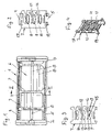
- FIG. 1 The drawing shows a cross section through an exemplary embodiment of a power transmission chain 1 according to the invention in the area of a chain link.
- Each chain link has two side plates 2 and 3, which are connected to each other by two crossbars, namely an upper crossbar 4 and a lower crossbar 5.
- the side plates 2 and 3 and the crossbars 4 and 5 form a guide channel 6 for receiving and Guide flexible lines such as cables, hoses and the like formed.
- the transverse webs 4, 5 can
- Opening bars (synonymous here with transverse bar), or e.g. be made in one piece with a side flap 2, 3.
- An opening web can, for example, be mounted pivotably on one side flap 2, 3 and can be latched to the other side flap 2, 3 or can be latched to both side flaps 2, 3 in a releasable manner.
- Each separating web 7 has two holding areas, each for holding on the respective crossbar 4, 5.
- the holding areas are a holding foot 18 and a holding head 19.
- the holding foot 18 is designed for locking or latching on a crossbar 5, in particular against displacement in the transverse direction along the crossbar 5, as in FIG.2 to see.
- the holding head 19 is held in the installed state of the separating web 7 on the transverse web 4 in the longitudinal direction without latching. If the energy guiding chain has opening bars, it is advantageous if the separating bar 7 is installed in such a way that the holding head 19 rests against an opening bar, so that the opening bar can be opened easily for maintenance purposes.
- the retaining foot 18 and the retaining head 19 each hold the separating web 7 in the installed position, ie with the chain link closed in the longitudinal direction so that they cannot be lost on the opposite transverse webs 4, 5.
- Each separating web 7 has a plate-like central area, which has the recesses 9 in the form of transverse to Main level has continuous openings.
- the main level of the divider 7 (cf. FIG.2/FIG.3 ) is the width direction and the height direction of the separating web 7, wherein the width direction corresponds to the longitudinal direction of the energy guiding chain 1 and the height direction corresponds to the direction perpendicular thereto and perpendicular to the transverse direction.
- the width direction corresponds to the longitudinal direction of the energy guiding chain 1
- the height direction corresponds to the direction perpendicular thereto and perpendicular to the transverse direction.
- At one of the lateral ends of the recesses 9 there is a continuous vertical rigid support area 10 which extends over the entire height of the separating web 7 and which is essentially inflexible.
- an insertion opening 11 which is connected to the recess 9 and serves for the insertion of a shelf 8 .
- the lateral insertion openings 11 are each combined with a resilient tongue element 12, which partially closes the respective insertion opening 11 and ensures that the respective inserted shelf 8 sits tightly in the respective recess 9 of the divider 7 after lateral insertion through the insertion openings 11.
- the resilient tongue element 12 extends from the insertion opening 11 to the opposite rigid support area 10 of the separating web 7, one end of the tongue element 12 being integrally connected to the edge of the respective insertion opening 11 and the other end to the rigid support area 10.
- a free space 13 is provided, into which the resilient tongue element 12 can yield elastically when inserting and removing the respective shelf 8 and, when the respective shelf 8 is inserted, hold it firmly in the recess 9 holds.
- the separating webs 7 are made of elastically deformable, very stable plastic.
- the separating webs can each be designed as a one-piece part, the elastic tongue elements 12 can also be integrally molded directly onto the material of the separating web 7 .
- One end of the respective tongue element 12 is formed onto the edge of the respective insertion opening 11 and the other end onto the vertical support area 10 .
- the separating webs 7 can be produced in particular using the injection molding process.
- the boundary wall 14 of the respective recess 9 opposite the resilient tongue element 12 is adapted to the outer contour of the plate-shaped shelf 8 to be inserted, so that the shelves sit firmly and securely in the recesses 9 and are fixed in the recesses in a stable and captive manner by means of the resilient tongue elements 12.
- the resilient tension elements 12 are arranged above the shelves 8 to be used. Alternatively, it would of course also be possible to reverse the position of the tongue elements 12 relative to the shelves 8, especially since when the energy guiding chain is reversed in the deflection bend in the opposite direction, top and bottom are swapped. In the exemplary embodiment shown, the resilient tension elements 12 are arranged on the side of the respective recess 9 which faces the holding head 19 .
- the resilient tongue elements 12 each have a protruding nose 15 on the side facing the respective recess 9, which additionally stabilizes the technical authorities used in the recesses.
- the provided on the tongue elements 12 projecting lugs 15 are arranged near the inner end of the insertion opening 11, so that thereby the seat of the shelves 8 is additionally secured in the recesses 9, so that an unintentional slipping out of the shelves 8 from the Recesses 9 is counteracted in the longitudinal direction of the energy guiding chain 1.
- This additional security is brought about in particular by the fact that the protruding nose 15 in the region of the end of the compartment base 8 facing the insertion opening 11 bears against it under pretension.
- the tongue element 12 has a latching projection 16 on the side facing the recess 9, which can hold an inserted shelf 8 in the direction transverse to the longitudinal direction of the chain or in the direction perpendicular to the main plane of the divider 7.
- the essence of the described energy guiding chain according to the invention is the new design of the separating webs, which serve to subdivide the guide channel 6 and form a particularly reliable holder for the shelves 8 running perpendicular to the separating webs 7 .
- the shelves 8 can be inserted into the recesses 9 of the dividers 7 in a very simple manner without the use of tools by pressing the shelves 8 through the insertion openings 11 into the recesses 9 of the dividers 7 without the entire divider 7 being elastically bent must become. This makes it possible to use a very stable material for the dividers.
- the dismantling of the shelves 8 is also very simple and can be done without the use of tools by simply pulling the shelves 8 out of the recesses 9 by hand through the insertion openings 11, with only the respective resilient tongue element 12 deforming and in the ones arranged behind it Space 13 recedes.
- the insertion openings 11 are offset upwards relative to the main axis of the recesses 9 , so that the insertion opening 11 opens into the recess 9 off-center and thereby forms a locking edge 17 .
- the latching edge 17 interacts with the locking lug 15 against an unintentional slipping out of the shelves 8 from the recesses 9 in the longitudinal direction of the energy guiding chain 1.
- the insertion openings 11 taper steadily towards the recesses 9 and are skewed upwards at an angle of approximately 10°-25° to the horizontal. This facilitates the assembly of the shelves from a predetermined side of the energy guiding chain 1, with the transverse web 4, 5 being designed as an opening web at least on this side.
Landscapes
- Engineering & Computer Science (AREA)
- General Engineering & Computer Science (AREA)
- Mechanical Engineering (AREA)
- Architecture (AREA)
- Civil Engineering (AREA)
- Structural Engineering (AREA)
- Electric Cable Arrangement Between Relatively Moving Parts (AREA)
- Battery Mounting, Suspending (AREA)
- Quick-Acting Or Multi-Walled Pipe Joints (AREA)
- Clamps And Clips (AREA)
- Buckles (AREA)
- Details Of Indoor Wiring (AREA)
- Installation Of Indoor Wiring (AREA)
- Supports For Pipes And Cables (AREA)
Claims (12)
- Bande de séparation (7) pour une chaîne porte-câbles constituée de maillons de chaîne reliés entre eux de manière pivotante, qui présentent deux pattes latérales (2, 3) qui sont reliées entre elles au moins pour certains maillons de chaîne par deux traverses (4, 5) et qui définissent un canal de guidage (6) pour des câbles, dans lequel des bandes de séparation (7) peuvent être disposées entre les traverses (4, 5) et peuvent être bloquées sur au moins l'une des traverses, et des étagères (8) en forme de plaques peuvent être disposées sensiblement perpendiculairement aux séparateurs (7),la bande de séparation présentant plusieurs évidements (9) dans chacun desquels une étagère (8) peut être maintenue, et à l'extrémité latérale de chaque évidement une zone de support rigide continue (10) et, à l'extrémité latérale opposée, une ouverture d'introduction (11) reliée à l'évidement respectif (9) pour l'insertion d'une étagère (8) sont prévues, etles ouvertures d'introduction étant pourvues chacune d'un élément de languette élastique (12) pour la fermeture partielle de l'ouverture d'introduction respective (11) et pour le maintien de l'étagère respective insérée (8),un espace libre (13) étant prévu sur le côté de l'élément de languette (12) qui est détourné de l'évidement (9), dans lequel l'élément de languette élastique (12) peut s'écarter élastiquement lors de l'insertion et du retrait d'une étagère (8),caractérisée en ce que- l'élément de languette élastique (12) s'étend essentiellement depuis l'ouverture d'introduction (11) jusqu'à la zone de support (10) opposée de la bande de séparation (7) et- en ce qu'une extrémité de l'élément de languette (12) est reliée au bord de l'ouverture d'introduction (11) et l'autre extrémité est reliée à la zone de support (10).
- Bande de séparation selon la revendication 1, caractérisée en ce que la bande de séparation est en matière plastique.
- Bande de séparation selon la revendication 2, caractérisée en ce que la bande de séparation (7) est conçu comme une pièce monobloc.
- Bande de séparation selon la revendication 3, caractérisée en ce qu'une extrémité de l'élément de languette (12) élastiquement déformable est formée d'un seul tenant sur le bord de l'ouverture d'introduction (11) et l'autre extrémité est également formée d'un seul tenant sur la zone de support (16) .
- Bande de séparation selon l'une des revendications 1 à 4, caractérisée en ce que la paroi de délimitation (14) de l'évidement (9) opposée à l'élément de languette élastique (12) est adaptée au contour extérieur de l'étagère en forme de plaque (8) à insérer.
- Bande de séparation selon l'une des revendications 1 à 5, caractérisée en ce que l'élément de languette (12) présente un ergot (15) en saillie sur le côté tourné vers l'évidement (9).
- Bande de séparation selon la revendication 6, caractérisée en ce que l'ergot en saillie (15) prévu sur l'élément de languette (12) est situé à proximité de l'extrémité intérieure de l'ouverture d'insertion (11).
- Bande de séparation selon la revendication 7, caractérisée en ce que, lorsque l'étagère (8) est en place, l'ergot en saillie (15) s'applique contre l'étagère (8) sous précontrainte dans la zone du côté de l'étagère (8) tourné vers l'ouverture d'introduction (11).
- Bande de séparation selon l'une des revendications 1 à 8, caractérisée en ce que toutes les ouvertures d'introduction (11) des évidements (9) sont disposées de manière à s'ouvrir vers le même côté de la bande de séparation.
- Bande de séparation selon l'une des revendications 1 à 9, caractérisée en ce que la dimension principale de l'espace libre (13) est supérieure à la dimension principale correspondante de l'évidement (9) associé et représente de préférence au moins 60% de la dimension de la bande de séparation dans la direction longitudinale de la chaîne.
- Bande de séparation selon l'une des revendications 1 à 10, caractérisée en ce que l'élément de languette (12) présente une saillie d'encliquetage (16) sur le côté tourné vers l'évidement (9), pour maintenir une étagère dans une direction transversale à la direction longitudinale de la chaîne.
- Chaîne porte-câble constituée de maillons de chaîne reliés entre eux de manière pivotante, qui présentent deux pattes latérales (2, 3) qui sont reliées entre elles au moins pour certains maillons de chaîne par deux traverses (4, 5) et qui définissent un canal de guidage (6) pour des câbles, comprenantdes bandes de séparation verticales (7), qui sont disposées entre les traverses (4, 5) et sont bloquées sur au moins une traverse (4, 5), ainsi quedes étagères horizontales (8) en forme de plaques, qui sont maintenues dans des évidements (9) des bandes de séparation (7),une zone de support rigide continue (10) étant prévue à une extrémité latérale de chaque évidement et une ouverture d'introduction (11) reliée à l'évidement (9) respectif étant prévue à l'extrémité latérale opposée pour l'introduction d'une étagère (8) et les ouvertures d'introduction étant pourvues chacune d'un élément à languette élastique (12) pour la fermeture partielle de l'ouverture d'introduction (11) respective afin de maintenir l'étagère (8) respective insérée,caractérisée en cequ'au moins une bande de séparation selon l'une des revendications 1 à 11 est prévue.
Applications Claiming Priority (2)
| Application Number | Priority Date | Filing Date | Title |
|---|---|---|---|
| DE202018101686.5U DE202018101686U1 (de) | 2018-03-26 | 2018-03-26 | Energieführungskette und Trennsteg hierfür |
| PCT/EP2019/057643 WO2019185662A1 (fr) | 2018-03-26 | 2019-03-26 | Bande de séparation pour une chaîne porte-câbles |
Publications (2)
| Publication Number | Publication Date |
|---|---|
| EP3776772A1 EP3776772A1 (fr) | 2021-02-17 |
| EP3776772B1 true EP3776772B1 (fr) | 2022-12-21 |
Family
ID=62026892
Family Applications (1)
| Application Number | Title | Priority Date | Filing Date |
|---|---|---|---|
| EP19714197.1A Active EP3776772B1 (fr) | 2018-03-26 | 2019-03-26 | Bande de séparation pour une chaîne porte-câbles |
Country Status (9)
| Country | Link |
|---|---|
| US (1) | US12085146B2 (fr) |
| EP (1) | EP3776772B1 (fr) |
| JP (1) | JP7250034B2 (fr) |
| KR (1) | KR20210004967A (fr) |
| CN (1) | CN112219328B (fr) |
| DE (1) | DE202018101686U1 (fr) |
| ES (1) | ES2938690T3 (fr) |
| PL (1) | PL3776772T3 (fr) |
| WO (1) | WO2019185662A1 (fr) |
Cited By (1)
| Publication number | Priority date | Publication date | Assignee | Title |
|---|---|---|---|---|
| DE202023101875U1 (de) | 2023-04-13 | 2024-07-19 | Igus Gmbh | Energieführungskette mit Trennstegen |
Families Citing this family (2)
| Publication number | Priority date | Publication date | Assignee | Title |
|---|---|---|---|---|
| DE202017100200U1 (de) * | 2017-01-16 | 2017-01-25 | Igus Gmbh | Trennsteg für Energieführungsketten |
| DE102018212951A1 (de) * | 2018-08-02 | 2020-02-06 | Deere & Company | Austrageinrichtung für eine landwirtschaftliche Erntemaschine |
Family Cites Families (10)
| Publication number | Priority date | Publication date | Assignee | Title |
|---|---|---|---|---|
| DE2255283C3 (de) * | 1972-11-11 | 1975-06-05 | Kabelschlepp Gmbh, 5900 Siegen | Energieführungskette |
| EP0382419B1 (fr) * | 1989-02-09 | 1994-07-13 | Mansign Engineering Limited | Dispositif de maintien de câble utilisé dans une chaîne porte-câbles |
| US5630738A (en) | 1994-07-21 | 1997-05-20 | Sumitomo Wiring Systems, Ltd. | Female terminal, metal fixture |
| DE19609146A1 (de) * | 1996-03-08 | 1997-09-11 | Murrplastik Systemtechnik Gmbh | Regal für Energieführungsketten |
| DE19860948C2 (de) | 1998-12-31 | 2002-02-14 | Igus Gmbh | Leitungsführungseinrichtung |
| DE202009005650U1 (de) | 2009-04-17 | 2009-07-02 | Igus Gmbh | Energieführungskette |
| DE202014101366U1 (de) | 2014-03-24 | 2014-03-28 | Igus Gmbh | Leitungsführungseinrichtung mit einstückigem Gelenk, entsprechendes Kettenglied und Gelenkband |
| DE202014103562U1 (de) * | 2014-07-31 | 2014-09-11 | Igus Gmbh | Führungseinrichtung |
| DE202015101707U1 (de) | 2015-04-07 | 2015-10-08 | Igus Gmbh | Energieführungskette und teilbarer Trennsteg hierfür |
| DE202017100200U1 (de) | 2017-01-16 | 2017-01-25 | Igus Gmbh | Trennsteg für Energieführungsketten |
-
2018
- 2018-03-26 DE DE202018101686.5U patent/DE202018101686U1/de active Active
-
2019
- 2019-03-26 US US17/041,645 patent/US12085146B2/en active Active
- 2019-03-26 KR KR1020207028070A patent/KR20210004967A/ko not_active Application Discontinuation
- 2019-03-26 PL PL19714197.1T patent/PL3776772T3/pl unknown
- 2019-03-26 EP EP19714197.1A patent/EP3776772B1/fr active Active
- 2019-03-26 CN CN201980028269.1A patent/CN112219328B/zh active Active
- 2019-03-26 JP JP2020551580A patent/JP7250034B2/ja active Active
- 2019-03-26 WO PCT/EP2019/057643 patent/WO2019185662A1/fr unknown
- 2019-03-26 ES ES19714197T patent/ES2938690T3/es active Active
Cited By (1)
| Publication number | Priority date | Publication date | Assignee | Title |
|---|---|---|---|---|
| DE202023101875U1 (de) | 2023-04-13 | 2024-07-19 | Igus Gmbh | Energieführungskette mit Trennstegen |
Also Published As
| Publication number | Publication date |
|---|---|
| EP3776772A1 (fr) | 2021-02-17 |
| KR20210004967A (ko) | 2021-01-13 |
| CN112219328B (zh) | 2022-10-14 |
| CN112219328A (zh) | 2021-01-12 |
| JP7250034B2 (ja) | 2023-03-31 |
| JP2021519401A (ja) | 2021-08-10 |
| PL3776772T3 (pl) | 2023-08-21 |
| US20210131527A1 (en) | 2021-05-06 |
| DE202018101686U1 (de) | 2018-04-09 |
| US12085146B2 (en) | 2024-09-10 |
| WO2019185662A1 (fr) | 2019-10-03 |
| ES2938690T3 (es) | 2023-04-13 |
Similar Documents
| Publication | Publication Date | Title |
|---|---|---|
| EP3776772B1 (fr) | Bande de séparation pour une chaîne porte-câbles | |
| EP2750550B1 (fr) | Tiroir | |
| EP3568610B1 (fr) | Bande de séparation pour chaînes de guidage d'énergie | |
| DE102010016591B4 (de) | Schubkasten und Trennelement für einen Schubkasten | |
| EP3688337B1 (fr) | Dispositif de guidage | |
| EP2468969B1 (fr) | Système du caniveau | |
| EP2689696A1 (fr) | Support d'une baguette élastique | |
| EP1865135B1 (fr) | Guide pour ferrure de porte coulissante | |
| EP1820423A1 (fr) | Console pour des lattes réglable en hauteur dans un sommier à latttes | |
| EP2022909B1 (fr) | Boite d'attente | |
| EP0786631B1 (fr) | Dispositif pour monter des objets, comme des radiateurs, contre un mur | |
| DE4335000A1 (de) | U-förmiges Verbindungselement zur Verbindung von C-Profilschienen aus Metall | |
| EP3120456B1 (fr) | Dispositif pour absorber le bruit électrique de câbles | |
| WO2005036025A1 (fr) | Eclisse de chaine, maillon de chaine et chaine de guidage d'energie ainsi que piece intermediaire pour une chaine de guidage d'energie pourvue de moyens de verrouillage couples en torsion pour la liaison d'une entretoise et d'une eclisse de chaine | |
| DE102006059180B4 (de) | Montagesystem für schienenmontable Gehäuse | |
| WO2017129499A1 (fr) | Dispositif d'encliquetage pour un bloc électrique et bloc pourvu d'un tel dispositif d'encliquetage | |
| DE2847978C2 (de) | Wischvorrichtung für Scheiben von Kraftfahrzeugen | |
| EP3447205B1 (fr) | Mise en place d'une couverture sur une gouttière | |
| DE102010025055B4 (de) | Pfostenverbinder | |
| DE102008015770B4 (de) | Versorgungseinheit für Unterfluranwendung | |
| DE19710625C2 (de) | Kunststoffkettenglied einer Energieführungskette | |
| EP2177667A1 (fr) | Cage ou élément de cage et marche | |
| EP3825481A1 (fr) | Répartiteur d'eau de chasse | |
| EP1086325A1 (fr) | Chainon pour chaines d'apport d'energie | |
| EP4065788A1 (fr) | Système de gouttière, unité de couvercle et élément de fixation |
Legal Events
| Date | Code | Title | Description |
|---|---|---|---|
| STAA | Information on the status of an ep patent application or granted ep patent |
Free format text: STATUS: UNKNOWN |
|
| STAA | Information on the status of an ep patent application or granted ep patent |
Free format text: STATUS: THE INTERNATIONAL PUBLICATION HAS BEEN MADE |
|
| PUAI | Public reference made under article 153(3) epc to a published international application that has entered the european phase |
Free format text: ORIGINAL CODE: 0009012 |
|
| STAA | Information on the status of an ep patent application or granted ep patent |
Free format text: STATUS: REQUEST FOR EXAMINATION WAS MADE |
|
| 17P | Request for examination filed |
Effective date: 20201008 |
|
| AK | Designated contracting states |
Kind code of ref document: A1 Designated state(s): AL AT BE BG CH CY CZ DE DK EE ES FI FR GB GR HR HU IE IS IT LI LT LU LV MC MK MT NL NO PL PT RO RS SE SI SK SM TR |
|
| AX | Request for extension of the european patent |
Extension state: BA ME |
|
| DAV | Request for validation of the european patent (deleted) | ||
| DAX | Request for extension of the european patent (deleted) | ||
| GRAP | Despatch of communication of intention to grant a patent |
Free format text: ORIGINAL CODE: EPIDOSNIGR1 |
|
| STAA | Information on the status of an ep patent application or granted ep patent |
Free format text: STATUS: GRANT OF PATENT IS INTENDED |
|
| GRAJ | Information related to disapproval of communication of intention to grant by the applicant or resumption of examination proceedings by the epo deleted |
Free format text: ORIGINAL CODE: EPIDOSDIGR1 |
|
| STAA | Information on the status of an ep patent application or granted ep patent |
Free format text: STATUS: REQUEST FOR EXAMINATION WAS MADE |
|
| INTG | Intention to grant announced |
Effective date: 20220809 |
|
| INTC | Intention to grant announced (deleted) | ||
| GRAP | Despatch of communication of intention to grant a patent |
Free format text: ORIGINAL CODE: EPIDOSNIGR1 |
|
| STAA | Information on the status of an ep patent application or granted ep patent |
Free format text: STATUS: GRANT OF PATENT IS INTENDED |
|
| GRAS | Grant fee paid |
Free format text: ORIGINAL CODE: EPIDOSNIGR3 |
|
| INTG | Intention to grant announced |
Effective date: 20221020 |
|
| GRAA | (expected) grant |
Free format text: ORIGINAL CODE: 0009210 |
|
| STAA | Information on the status of an ep patent application or granted ep patent |
Free format text: STATUS: THE PATENT HAS BEEN GRANTED |
|
| AK | Designated contracting states |
Kind code of ref document: B1 Designated state(s): AL AT BE BG CH CY CZ DE DK EE ES FI FR GB GR HR HU IE IS IT LI LT LU LV MC MK MT NL NO PL PT RO RS SE SI SK SM TR |
|
| REG | Reference to a national code |
Ref country code: GB Ref legal event code: FG4D Free format text: NOT ENGLISH |
|
| REG | Reference to a national code |
Ref country code: DE Ref legal event code: R096 Ref document number: 502019006581 Country of ref document: DE |
|
| REG | Reference to a national code |
Ref country code: CH Ref legal event code: EP |
|
| REG | Reference to a national code |
Ref country code: AT Ref legal event code: REF Ref document number: 1539619 Country of ref document: AT Kind code of ref document: T Effective date: 20230115 |
|
| REG | Reference to a national code |
Ref country code: IE Ref legal event code: FG4D Free format text: LANGUAGE OF EP DOCUMENT: GERMAN |
|
| REG | Reference to a national code |
Ref country code: NL Ref legal event code: FP |
|
| REG | Reference to a national code |
Ref country code: LT Ref legal event code: MG9D |
|
| REG | Reference to a national code |
Ref country code: ES Ref legal event code: FG2A Ref document number: 2938690 Country of ref document: ES Kind code of ref document: T3 Effective date: 20230413 |
|
| PG25 | Lapsed in a contracting state [announced via postgrant information from national office to epo] |
Ref country code: SE Free format text: LAPSE BECAUSE OF FAILURE TO SUBMIT A TRANSLATION OF THE DESCRIPTION OR TO PAY THE FEE WITHIN THE PRESCRIBED TIME-LIMIT Effective date: 20221221 Ref country code: NO Free format text: LAPSE BECAUSE OF FAILURE TO SUBMIT A TRANSLATION OF THE DESCRIPTION OR TO PAY THE FEE WITHIN THE PRESCRIBED TIME-LIMIT Effective date: 20230321 Ref country code: LT Free format text: LAPSE BECAUSE OF FAILURE TO SUBMIT A TRANSLATION OF THE DESCRIPTION OR TO PAY THE FEE WITHIN THE PRESCRIBED TIME-LIMIT Effective date: 20221221 Ref country code: FI Free format text: LAPSE BECAUSE OF FAILURE TO SUBMIT A TRANSLATION OF THE DESCRIPTION OR TO PAY THE FEE WITHIN THE PRESCRIBED TIME-LIMIT Effective date: 20221221 |
|
| PG25 | Lapsed in a contracting state [announced via postgrant information from national office to epo] |
Ref country code: RS Free format text: LAPSE BECAUSE OF FAILURE TO SUBMIT A TRANSLATION OF THE DESCRIPTION OR TO PAY THE FEE WITHIN THE PRESCRIBED TIME-LIMIT Effective date: 20221221 Ref country code: LV Free format text: LAPSE BECAUSE OF FAILURE TO SUBMIT A TRANSLATION OF THE DESCRIPTION OR TO PAY THE FEE WITHIN THE PRESCRIBED TIME-LIMIT Effective date: 20221221 Ref country code: HR Free format text: LAPSE BECAUSE OF FAILURE TO SUBMIT A TRANSLATION OF THE DESCRIPTION OR TO PAY THE FEE WITHIN THE PRESCRIBED TIME-LIMIT Effective date: 20221221 Ref country code: GR Free format text: LAPSE BECAUSE OF FAILURE TO SUBMIT A TRANSLATION OF THE DESCRIPTION OR TO PAY THE FEE WITHIN THE PRESCRIBED TIME-LIMIT Effective date: 20230322 |
|
| P01 | Opt-out of the competence of the unified patent court (upc) registered |
Effective date: 20230526 |
|
| PG25 | Lapsed in a contracting state [announced via postgrant information from national office to epo] |
Ref country code: SM Free format text: LAPSE BECAUSE OF FAILURE TO SUBMIT A TRANSLATION OF THE DESCRIPTION OR TO PAY THE FEE WITHIN THE PRESCRIBED TIME-LIMIT Effective date: 20221221 Ref country code: RO Free format text: LAPSE BECAUSE OF FAILURE TO SUBMIT A TRANSLATION OF THE DESCRIPTION OR TO PAY THE FEE WITHIN THE PRESCRIBED TIME-LIMIT Effective date: 20221221 Ref country code: PT Free format text: LAPSE BECAUSE OF FAILURE TO SUBMIT A TRANSLATION OF THE DESCRIPTION OR TO PAY THE FEE WITHIN THE PRESCRIBED TIME-LIMIT Effective date: 20230421 Ref country code: EE Free format text: LAPSE BECAUSE OF FAILURE TO SUBMIT A TRANSLATION OF THE DESCRIPTION OR TO PAY THE FEE WITHIN THE PRESCRIBED TIME-LIMIT Effective date: 20221221 Ref country code: CZ Free format text: LAPSE BECAUSE OF FAILURE TO SUBMIT A TRANSLATION OF THE DESCRIPTION OR TO PAY THE FEE WITHIN THE PRESCRIBED TIME-LIMIT Effective date: 20221221 |
|
| PG25 | Lapsed in a contracting state [announced via postgrant information from national office to epo] |
Ref country code: SK Free format text: LAPSE BECAUSE OF FAILURE TO SUBMIT A TRANSLATION OF THE DESCRIPTION OR TO PAY THE FEE WITHIN THE PRESCRIBED TIME-LIMIT Effective date: 20221221 Ref country code: IS Free format text: LAPSE BECAUSE OF FAILURE TO SUBMIT A TRANSLATION OF THE DESCRIPTION OR TO PAY THE FEE WITHIN THE PRESCRIBED TIME-LIMIT Effective date: 20230421 Ref country code: AL Free format text: LAPSE BECAUSE OF FAILURE TO SUBMIT A TRANSLATION OF THE DESCRIPTION OR TO PAY THE FEE WITHIN THE PRESCRIBED TIME-LIMIT Effective date: 20221221 |
|
| REG | Reference to a national code |
Ref country code: DE Ref legal event code: R097 Ref document number: 502019006581 Country of ref document: DE |
|
| PLBE | No opposition filed within time limit |
Free format text: ORIGINAL CODE: 0009261 |
|
| STAA | Information on the status of an ep patent application or granted ep patent |
Free format text: STATUS: NO OPPOSITION FILED WITHIN TIME LIMIT |
|
| PG25 | Lapsed in a contracting state [announced via postgrant information from national office to epo] |
Ref country code: MC Free format text: LAPSE BECAUSE OF FAILURE TO SUBMIT A TRANSLATION OF THE DESCRIPTION OR TO PAY THE FEE WITHIN THE PRESCRIBED TIME-LIMIT Effective date: 20221221 Ref country code: DK Free format text: LAPSE BECAUSE OF FAILURE TO SUBMIT A TRANSLATION OF THE DESCRIPTION OR TO PAY THE FEE WITHIN THE PRESCRIBED TIME-LIMIT Effective date: 20221221 |
|
| 26N | No opposition filed |
Effective date: 20230922 |
|
| REG | Reference to a national code |
Ref country code: BE Ref legal event code: MM Effective date: 20230331 |
|
| PG25 | Lapsed in a contracting state [announced via postgrant information from national office to epo] |
Ref country code: LU Free format text: LAPSE BECAUSE OF NON-PAYMENT OF DUE FEES Effective date: 20230326 |
|
| REG | Reference to a national code |
Ref country code: IE Ref legal event code: MM4A |
|
| PG25 | Lapsed in a contracting state [announced via postgrant information from national office to epo] |
Ref country code: SI Free format text: LAPSE BECAUSE OF FAILURE TO SUBMIT A TRANSLATION OF THE DESCRIPTION OR TO PAY THE FEE WITHIN THE PRESCRIBED TIME-LIMIT Effective date: 20221221 Ref country code: IE Free format text: LAPSE BECAUSE OF NON-PAYMENT OF DUE FEES Effective date: 20230326 |
|
| PG25 | Lapsed in a contracting state [announced via postgrant information from national office to epo] |
Ref country code: BE Free format text: LAPSE BECAUSE OF NON-PAYMENT OF DUE FEES Effective date: 20230331 |
|
| PGFP | Annual fee paid to national office [announced via postgrant information from national office to epo] |
Ref country code: NL Payment date: 20240320 Year of fee payment: 6 |
|
| PGFP | Annual fee paid to national office [announced via postgrant information from national office to epo] |
Ref country code: AT Payment date: 20240318 Year of fee payment: 6 |
|
| PGFP | Annual fee paid to national office [announced via postgrant information from national office to epo] |
Ref country code: GB Payment date: 20240322 Year of fee payment: 6 |
|
| PGFP | Annual fee paid to national office [announced via postgrant information from national office to epo] |
Ref country code: PL Payment date: 20240315 Year of fee payment: 6 Ref country code: IT Payment date: 20240329 Year of fee payment: 6 Ref country code: FR Payment date: 20240320 Year of fee payment: 6 |
|
| PGFP | Annual fee paid to national office [announced via postgrant information from national office to epo] |
Ref country code: DE Payment date: 20240527 Year of fee payment: 6 |
|
| PGFP | Annual fee paid to national office [announced via postgrant information from national office to epo] |
Ref country code: CH Payment date: 20240401 Year of fee payment: 6 |
|
| PGFP | Annual fee paid to national office [announced via postgrant information from national office to epo] |
Ref country code: ES Payment date: 20240417 Year of fee payment: 6 |