EP3775663B1 - Verstellbarer tragarm - Google Patents
Verstellbarer tragarm Download PDFInfo
- Publication number
- EP3775663B1 EP3775663B1 EP19781080.7A EP19781080A EP3775663B1 EP 3775663 B1 EP3775663 B1 EP 3775663B1 EP 19781080 A EP19781080 A EP 19781080A EP 3775663 B1 EP3775663 B1 EP 3775663B1
- Authority
- EP
- European Patent Office
- Prior art keywords
- arm
- adjustable
- support arm
- insert
- assembly
- Prior art date
- Legal status (The legal status is an assumption and is not a legal conclusion. Google has not performed a legal analysis and makes no representation as to the accuracy of the status listed.)
- Active
Links
Images


Classifications
-
- F—MECHANICAL ENGINEERING; LIGHTING; HEATING; WEAPONS; BLASTING
- F16—ENGINEERING ELEMENTS AND UNITS; GENERAL MEASURES FOR PRODUCING AND MAINTAINING EFFECTIVE FUNCTIONING OF MACHINES OR INSTALLATIONS; THERMAL INSULATION IN GENERAL
- F16M—FRAMES, CASINGS OR BEDS OF ENGINES, MACHINES OR APPARATUS, NOT SPECIFIC TO ENGINES, MACHINES OR APPARATUS PROVIDED FOR ELSEWHERE; STANDS; SUPPORTS
- F16M11/00—Stands or trestles as supports for apparatus or articles placed thereon ; Stands for scientific apparatus such as gravitational force meters
- F16M11/02—Heads
- F16M11/04—Means for attachment of apparatus; Means allowing adjustment of the apparatus relatively to the stand
- F16M11/06—Means for attachment of apparatus; Means allowing adjustment of the apparatus relatively to the stand allowing pivoting
- F16M11/12—Means for attachment of apparatus; Means allowing adjustment of the apparatus relatively to the stand allowing pivoting in more than one direction
- F16M11/121—Means for attachment of apparatus; Means allowing adjustment of the apparatus relatively to the stand allowing pivoting in more than one direction constituted of several dependent joints
-
- F—MECHANICAL ENGINEERING; LIGHTING; HEATING; WEAPONS; BLASTING
- F16—ENGINEERING ELEMENTS AND UNITS; GENERAL MEASURES FOR PRODUCING AND MAINTAINING EFFECTIVE FUNCTIONING OF MACHINES OR INSTALLATIONS; THERMAL INSULATION IN GENERAL
- F16M—FRAMES, CASINGS OR BEDS OF ENGINES, MACHINES OR APPARATUS, NOT SPECIFIC TO ENGINES, MACHINES OR APPARATUS PROVIDED FOR ELSEWHERE; STANDS; SUPPORTS
- F16M11/00—Stands or trestles as supports for apparatus or articles placed thereon ; Stands for scientific apparatus such as gravitational force meters
- F16M11/02—Heads
- F16M11/04—Means for attachment of apparatus; Means allowing adjustment of the apparatus relatively to the stand
- F16M11/041—Allowing quick release of the apparatus
-
- F—MECHANICAL ENGINEERING; LIGHTING; HEATING; WEAPONS; BLASTING
- F16—ENGINEERING ELEMENTS AND UNITS; GENERAL MEASURES FOR PRODUCING AND MAINTAINING EFFECTIVE FUNCTIONING OF MACHINES OR INSTALLATIONS; THERMAL INSULATION IN GENERAL
- F16M—FRAMES, CASINGS OR BEDS OF ENGINES, MACHINES OR APPARATUS, NOT SPECIFIC TO ENGINES, MACHINES OR APPARATUS PROVIDED FOR ELSEWHERE; STANDS; SUPPORTS
- F16M11/00—Stands or trestles as supports for apparatus or articles placed thereon ; Stands for scientific apparatus such as gravitational force meters
- F16M11/02—Heads
- F16M11/04—Means for attachment of apparatus; Means allowing adjustment of the apparatus relatively to the stand
- F16M11/06—Means for attachment of apparatus; Means allowing adjustment of the apparatus relatively to the stand allowing pivoting
- F16M11/08—Means for attachment of apparatus; Means allowing adjustment of the apparatus relatively to the stand allowing pivoting around a vertical axis, e.g. panoramic heads
-
- F—MECHANICAL ENGINEERING; LIGHTING; HEATING; WEAPONS; BLASTING
- F16—ENGINEERING ELEMENTS AND UNITS; GENERAL MEASURES FOR PRODUCING AND MAINTAINING EFFECTIVE FUNCTIONING OF MACHINES OR INSTALLATIONS; THERMAL INSULATION IN GENERAL
- F16M—FRAMES, CASINGS OR BEDS OF ENGINES, MACHINES OR APPARATUS, NOT SPECIFIC TO ENGINES, MACHINES OR APPARATUS PROVIDED FOR ELSEWHERE; STANDS; SUPPORTS
- F16M11/00—Stands or trestles as supports for apparatus or articles placed thereon ; Stands for scientific apparatus such as gravitational force meters
- F16M11/02—Heads
- F16M11/04—Means for attachment of apparatus; Means allowing adjustment of the apparatus relatively to the stand
- F16M11/06—Means for attachment of apparatus; Means allowing adjustment of the apparatus relatively to the stand allowing pivoting
- F16M11/10—Means for attachment of apparatus; Means allowing adjustment of the apparatus relatively to the stand allowing pivoting around a horizontal axis
- F16M11/105—Means for attachment of apparatus; Means allowing adjustment of the apparatus relatively to the stand allowing pivoting around a horizontal axis the horizontal axis being the roll axis, e.g. for creating a landscape-portrait rotation
-
- F—MECHANICAL ENGINEERING; LIGHTING; HEATING; WEAPONS; BLASTING
- F16—ENGINEERING ELEMENTS AND UNITS; GENERAL MEASURES FOR PRODUCING AND MAINTAINING EFFECTIVE FUNCTIONING OF MACHINES OR INSTALLATIONS; THERMAL INSULATION IN GENERAL
- F16M—FRAMES, CASINGS OR BEDS OF ENGINES, MACHINES OR APPARATUS, NOT SPECIFIC TO ENGINES, MACHINES OR APPARATUS PROVIDED FOR ELSEWHERE; STANDS; SUPPORTS
- F16M11/00—Stands or trestles as supports for apparatus or articles placed thereon ; Stands for scientific apparatus such as gravitational force meters
- F16M11/02—Heads
- F16M11/16—Details concerning attachment of head-supporting legs, with or without actuation of locking members thereof
-
- F—MECHANICAL ENGINEERING; LIGHTING; HEATING; WEAPONS; BLASTING
- F16—ENGINEERING ELEMENTS AND UNITS; GENERAL MEASURES FOR PRODUCING AND MAINTAINING EFFECTIVE FUNCTIONING OF MACHINES OR INSTALLATIONS; THERMAL INSULATION IN GENERAL
- F16M—FRAMES, CASINGS OR BEDS OF ENGINES, MACHINES OR APPARATUS, NOT SPECIFIC TO ENGINES, MACHINES OR APPARATUS PROVIDED FOR ELSEWHERE; STANDS; SUPPORTS
- F16M11/00—Stands or trestles as supports for apparatus or articles placed thereon ; Stands for scientific apparatus such as gravitational force meters
- F16M11/20—Undercarriages with or without wheels
- F16M11/2007—Undercarriages with or without wheels comprising means allowing pivoting adjustment
- F16M11/2014—Undercarriages with or without wheels comprising means allowing pivoting adjustment around a vertical axis
-
- F—MECHANICAL ENGINEERING; LIGHTING; HEATING; WEAPONS; BLASTING
- F16—ENGINEERING ELEMENTS AND UNITS; GENERAL MEASURES FOR PRODUCING AND MAINTAINING EFFECTIVE FUNCTIONING OF MACHINES OR INSTALLATIONS; THERMAL INSULATION IN GENERAL
- F16M—FRAMES, CASINGS OR BEDS OF ENGINES, MACHINES OR APPARATUS, NOT SPECIFIC TO ENGINES, MACHINES OR APPARATUS PROVIDED FOR ELSEWHERE; STANDS; SUPPORTS
- F16M11/00—Stands or trestles as supports for apparatus or articles placed thereon ; Stands for scientific apparatus such as gravitational force meters
- F16M11/20—Undercarriages with or without wheels
- F16M11/2007—Undercarriages with or without wheels comprising means allowing pivoting adjustment
- F16M11/2035—Undercarriages with or without wheels comprising means allowing pivoting adjustment in more than one direction
- F16M11/2064—Undercarriages with or without wheels comprising means allowing pivoting adjustment in more than one direction for tilting and panning
-
- F—MECHANICAL ENGINEERING; LIGHTING; HEATING; WEAPONS; BLASTING
- F16—ENGINEERING ELEMENTS AND UNITS; GENERAL MEASURES FOR PRODUCING AND MAINTAINING EFFECTIVE FUNCTIONING OF MACHINES OR INSTALLATIONS; THERMAL INSULATION IN GENERAL
- F16M—FRAMES, CASINGS OR BEDS OF ENGINES, MACHINES OR APPARATUS, NOT SPECIFIC TO ENGINES, MACHINES OR APPARATUS PROVIDED FOR ELSEWHERE; STANDS; SUPPORTS
- F16M11/00—Stands or trestles as supports for apparatus or articles placed thereon ; Stands for scientific apparatus such as gravitational force meters
- F16M11/20—Undercarriages with or without wheels
- F16M11/24—Undercarriages with or without wheels changeable in height or length of legs, also for transport only, e.g. by means of tubes screwed into each other
- F16M11/26—Undercarriages with or without wheels changeable in height or length of legs, also for transport only, e.g. by means of tubes screwed into each other by telescoping, with or without folding
-
- F—MECHANICAL ENGINEERING; LIGHTING; HEATING; WEAPONS; BLASTING
- F16—ENGINEERING ELEMENTS AND UNITS; GENERAL MEASURES FOR PRODUCING AND MAINTAINING EFFECTIVE FUNCTIONING OF MACHINES OR INSTALLATIONS; THERMAL INSULATION IN GENERAL
- F16M—FRAMES, CASINGS OR BEDS OF ENGINES, MACHINES OR APPARATUS, NOT SPECIFIC TO ENGINES, MACHINES OR APPARATUS PROVIDED FOR ELSEWHERE; STANDS; SUPPORTS
- F16M13/00—Other supports for positioning apparatus or articles; Means for steadying hand-held apparatus or articles
- F16M13/02—Other supports for positioning apparatus or articles; Means for steadying hand-held apparatus or articles for supporting on, or attaching to, an object, e.g. tree, gate, window-frame, cycle
- F16M13/022—Other supports for positioning apparatus or articles; Means for steadying hand-held apparatus or articles for supporting on, or attaching to, an object, e.g. tree, gate, window-frame, cycle repositionable
-
- F—MECHANICAL ENGINEERING; LIGHTING; HEATING; WEAPONS; BLASTING
- F16—ENGINEERING ELEMENTS AND UNITS; GENERAL MEASURES FOR PRODUCING AND MAINTAINING EFFECTIVE FUNCTIONING OF MACHINES OR INSTALLATIONS; THERMAL INSULATION IN GENERAL
- F16M—FRAMES, CASINGS OR BEDS OF ENGINES, MACHINES OR APPARATUS, NOT SPECIFIC TO ENGINES, MACHINES OR APPARATUS PROVIDED FOR ELSEWHERE; STANDS; SUPPORTS
- F16M11/00—Stands or trestles as supports for apparatus or articles placed thereon ; Stands for scientific apparatus such as gravitational force meters
- F16M11/20—Undercarriages with or without wheels
- F16M11/2092—Undercarriages with or without wheels comprising means allowing depth adjustment, i.e. forward-backward translation of the head relatively to the undercarriage
-
- F—MECHANICAL ENGINEERING; LIGHTING; HEATING; WEAPONS; BLASTING
- F16—ENGINEERING ELEMENTS AND UNITS; GENERAL MEASURES FOR PRODUCING AND MAINTAINING EFFECTIVE FUNCTIONING OF MACHINES OR INSTALLATIONS; THERMAL INSULATION IN GENERAL
- F16M—FRAMES, CASINGS OR BEDS OF ENGINES, MACHINES OR APPARATUS, NOT SPECIFIC TO ENGINES, MACHINES OR APPARATUS PROVIDED FOR ELSEWHERE; STANDS; SUPPORTS
- F16M2200/00—Details of stands or supports
- F16M2200/02—Locking means
- F16M2200/021—Locking means for rotational movement
- F16M2200/024—Locking means for rotational movement by positive interaction, e.g. male-female connections
-
- F—MECHANICAL ENGINEERING; LIGHTING; HEATING; WEAPONS; BLASTING
- F16—ENGINEERING ELEMENTS AND UNITS; GENERAL MEASURES FOR PRODUCING AND MAINTAINING EFFECTIVE FUNCTIONING OF MACHINES OR INSTALLATIONS; THERMAL INSULATION IN GENERAL
- F16M—FRAMES, CASINGS OR BEDS OF ENGINES, MACHINES OR APPARATUS, NOT SPECIFIC TO ENGINES, MACHINES OR APPARATUS PROVIDED FOR ELSEWHERE; STANDS; SUPPORTS
- F16M2200/00—Details of stands or supports
- F16M2200/06—Arms
- F16M2200/063—Parallelogram arms
Definitions
- Adjustable support arms allow mounted objects such as electronic displays, keyboards, or other items to be moved to the appropriate ergonomic position relative to the user. By enabling users to align the monitor at the correct height for them, adjustable support arms encourage a healthier, more ergonomic working posture which helps prevent eye and neck strain. Additionally, they preserve precious workspace by floating the monitor above the user's work surface.
- adjustable support arms In today's modem workplace, adjustable support arms must provide users with a wide range of height, depth, and angle adjustments. For example, when changing from a seated position to a standing position at height-adjustable desks, users oftentimes will desire that the monitor, keyboard and other equipment be at adjusted to different positions. Similarly, where the concept of hot-desking is employed in the workplace, a given workstation must be capable of accommodating different users of different sizes throughout the workday. Accordingly, an adjustable support arm offering improved adjustability over a wide range of travel would be beneficial.
- US 2015/377283 A1 discloses a rotatable connection for a mount device for placement in an operating room.
- the rotatable connection includes an adjustable stopping mechanism that can be disposed between a first connection component and a second connection component that is mounted rotatably relative to the first connection component about an axis of rotation.
- the adjustable stopping mechanism may be adapted to establish at least two different relative rotational angles of the connection components relative to one another or at least two different rotation ranges.
- the adjustable stopping mechanism includes a rotation lock that can be disposed non-rotatingly at the first connection component and a coupling part that can be disposed non-rotatingly at the second connection component and that has a form-locking contour for establishing individual rotational angle positions, and may include a stopping device with an integral stop.
- the stopping device may be non-rotatingly positionable.
- US 2015/366627 A1 also dislcoses a rotatable connection for a mounting device for arrangement in an operating room.
- the rotatable connection includes an adjustable stop mechanism, which can be disposed between a first connection component and a second connection component, and is configured to define at least two different relative rotational angles of the connection components relative to each other or at least two different ranges or rotation.
- the adjustable stop mechanism includes at least one stop device having a define the different relative rotational angles or ranges of rotation by way of the respective counterstop.
- US 2012/228454 A1 discloses a rotatable joint.
- a first joint member connects to a reference frame.
- a second joint member is connected with the first joint member and configured for rotation relative to the first joint member about an axis.
- An adjustable stop mechanism defines limits of rotation of the second joint member relative to the first joint member.
- the adjustable stop mechanism comprises a first part provided on the first joint member having at least a first stop defining at least a first limit of rotation of the second joint member about said axis relative to the first joint member.
- the first part is adapted to be selectively positioned with respect to the first joint member to set or define a limit or range of rotation of the second joint member relative to the first joint member.
- the terms “a” or “an” are defined as one or more.
- the term “plurality,” as used herein, is defined as two or more.
- the term “another,” as used herein, is defined as at least a second or more.
- the terms “comprises,” “comprising,” or any other variation thereof are intended to cover a non-exclusive inclusion, such that a process, method, article, or apparatus that comprises a list of elements does not include only those elements, but may include other elements not expressly listed or inherent to such process, method, article, or apparatus.
- An element proceeded by "comprises ... a” does not, without more constraints, preclude the existence of additional identical elements in the process, method, article, or apparatus that comprises the element.
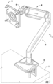
- the adjustable support arm 1 may comprise a base assembly 10, an arm assembly (20, 30) releasably mounted to the base assembly 10, an articulating joint 40 connected to the arm assembly (20, 30), and an accessory bracket assembly 50 connected to the articulating joint 40.
- the arm assembly may comprise a second arm 30 releasably mounted to a first arm 20.
- the second arm 30 is a dynamic arm while the first arm 20 is a static arm.
- the dynamic arm allows a user to optimize both the vertical and horizontal positioning of the accessory bracket assembly 50 relative to the user, thus providing the adjustable support arm 1 a wide range of height adjustability.
- the dynamic arm can be a counter-balanced, parallelogram support arm, such as U.S. Pat. No. 9,657,889 to Chumakov .
- the dynamic arm 30 can be a single bar, pivot arm or any other known dynamic arm capable of providing height adjustability.
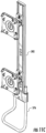
- the static arm can be a riser arm (e.g., Figures 1-3 ) designed to further optimize the vertical and horizontal positioning of the accessory bracket assembly 50, or the static arm can be a horizontal extension arm (e.g., Figure 16 ) adapted for adjusting the horizontal positioning of the accessory bracket assembly 50 and any attached accessory relative to the base assembly 10.
- the arm assembly can comprise a first arm only, with the first arm being either a dynamic arm or a static arm releasably mounted directly to the base assembly 10.
- the adjustable support arm 1 can optionally exclude both the second arm 30 and the articulating joint 40, with the first arm 20 having one end connected to the base assembly 10 and the other end connected to the accessory bracket assembly 50.
- the base assembly 10 functions to mount the adjustable support arm 1 to a work surface or other fixture, such as a slat wall.
- the base assembly 10 may comprise a base plate 13 adapted to be positioned on the top of a work surface 3, a post 14 extending upward from the base plate 13, a clamp bracket 11 attached to the base plate 13 and extending below the work surface, and a screw 12 threadingly engaged with the clamp bracket 11.
- the user can rotate the screw 12 until the screw's distal end comes into contact with the underside of the work surface.
- the exemplary embodiment of the base assembly 10 depicted in Figures 1-3 is configured to be mounted to the work surface 3 of an office desk.
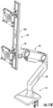
- FIGS 14A and 14B depict a base assembly 1000 configured for attachment to a slatwall.
- the base assembly 1000 can comprise first and second protrusions 1005,1007 adapted to engage grooves in a slatwall.
- the base assembly 1000 can further comprise a post 1014 housing a first release joint 100 and a panning insert as shown.
- Figure 15 depicts an exemplary base assembly 1100 comprising a mounting plate 1105 and a plurality of screws 1106 for mounting the adjustable support arm 1 directly to a wall.
- each of the various embodiments of the base assembly may be configured to comprise two or more posts 14a,14b for attaching multiple arm assemblies to the base assembly, and the posts may contain the panning inserts.
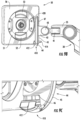
- a first end 21 of the first arm 20 can be releasably attached to the post 14 utilizing a first connector shaft 80 coupled to a first release joint 100.
- the first release joint 100 may engage the first connector shaft 80 to secure the first arm 20 to the post 14 of the base assembly 10.
- a user can access the first release joint 100 through a slot 17 positioned on the posterior side 14 p of the post 14.
- the slot 17 through which the first release joint 100 is accessed can be positioned on the anterior side 14 a of the post 14, or on any other side of the post.
- the first arm 20 may be attached to the base assembly 10 in a manner allowing a user the ability to adjust the front-to-back positioning (i.e., depth) of the support arm 1 by rotating the first arm 20 about its connection to the base assembly 10.
- the first arm 20 may be attached to the base assembly 10 in a manner preventing rotation of the first arm 20 relative to the base assembly 10.
- the second arm 30 can comprise a parallelogram linkage 31 having a first end 32 pivotally attached to a lower bracket 34 and a second end 33 pivotally attached to an upper bracket 35.
- the lower bracket 34 of the second arm 30 can be releasably attached to the second end 22 of the first arm 20 utilizing a second connector shaft 81 coupled to a second release joint 200.
- a user can access the second release joint 200 through a slot 25 formed on the posterior side 22 p of the second end 22 of the first arm 20.
- the user can access the second release joint 200 through a slot 25 formed on the anterior side 22 a of the second end 22 of the first arm 20, or on any other side of the second end 22 of the first arm 20.
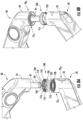
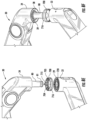
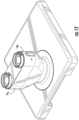
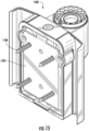
- the articulating joint 40 functions to provide the attached accessory bracket assembly 50 a wide range of adjustability, such as panning/swiveling (i.e., a left or right angled movement), tilting (i.e., an upward or downward angled movement), and/or rotation (i.e., turning from landscape to portrait view).
- the articulating joint 40 can comprise a swivel ring 41, a tilt ring 42 attached to the swivel ring 41, and a mounting plate 44 attached to the tilt ring 42.
- the swivel ring 41 can be attached to the upper bracket 35 via a swivel pin 36 so as to allow side-to-side panning movement.
- the mounting plate 44 can be attached to the tilt ring 42 via a tilt pin 43 so as to allow up-to-down tilting movement.
- the articulating joint 40 can take on a variety of forms.
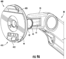
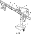
- a turret-style articulating joint 40 is depicted in Figure 13A .
- the turret-style articulating joint 40 can comprise a turret 48 capable of being secured to the second arm 30, a tilt hub 49 pivotally attached to the turret 48, and a mounting plate 44 attached to the tilt hub 49.
- the accessory bracket assembly 50 can be releasably attached to the mounting plate 44.
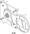
- An embodiment of the accessory bracket assembly 50 is depicted in Figures 10A and 10B .
- the accessory bracket assembly 50 can comprise a central bracket 51 positioned within a frame 56.
- the frame 56 may comprise a VESA plate adhering to the standards created by the Video Electronics Standards Association, but can comprise other plates or mounts suitable for mounting various electronic equipment, including Apple ® products.
- the frame 56 has an inner cavity for housing the central bracket 51.
- the frame 56 can be secured to the central bracket 51 with one or more fasteners.
- the frame 56 comprises a 100x100 VESA plate.
- Figure 9D shows an alternative embodiment of the accessory bracket assembly whereby a 100x200 frame 58 is attached to the central bracket 51.
- an adaptor bracket may be attached to the central bracket 51 to allow for non-VESA compliant accessories to be mounted to the support arm 1.
- Figure 9G depicts an alternative embodiment of the accessory bracket assembly 50 whereby an offset central bracket 51 comprising a horizontal beam 55 is pivotally attached to a VESA bracket 59, thereby allowing the accessory mounted to the VESA bracket 59 to be positioned in an offset orientation relative to the offset central bracket 51.
- any suitable frame or bracket can be utilized to attach the desired accessories to the monitor arm of the invention.
- the adjustable support arm 1 may comprise one or more quick-release joints for releasably connecting the components of the adjustable support arm 1.
- a first quick-release joint 100 may be utilized to releasably connect the arm assembly 20,30 to the base assembly 10
- a second quick-release joint 200 may be utilized to releasably connect the second arm 30 to the first arm 20 in embodiments where a second arm 30 is utilized.
- the second release joint 200 can comprise a latch 210, an axle 215, and a spring 217.
- the latch 210 can comprise an upper portion 211, a lower portion 212 having a protrusion 218, and an aperture 213 positioned between the upper and lower portions 211, 212.
- the latch 210 can be pivotally connected to the second end 22 of the first arm 20 via an axle 215 extending through the aperture 213, with the axle 215 functioning as a fulcrum about which the latch 210 pivots.
- the connector shaft 81 can be secured within the central chamber 37 of the lower bracket 34 by any means known in the art, such as via a bolt or by way of a pressure fitting.
- a user can attach the second arm 30 to the first arm 20 by sliding the connector shaft 81 into the central bore 23 formed in the second end 22 of the static arm 20.
- a spring 217 can be positioned between the static arm 20 and the upper portion 211 of the latch 210 to bias the latch's protrusion 218 into engagement with the indentation 84, thus locking the second arm 30 into connection with the first arm 20.
- the connector shaft 81 will move relative to the central bore 23 formed in the second end 22 of the first arm 20, with the connector shaft 81 and the central bore 23 preferably being in frictional engagement to minimize slack in the joint and provide damping.
- a user can access the second release joint 200 through the slot 25 formed in the second end of the first arm 20.
- the latch 210 will rotate about the axis and thus cause the protrusion 218 to disengage from the indentation 84 in the connector shaft 81, thus allowing the user to lift the second arm 30 from the central bore 23 formed in the second end 22 of the first arm 20.
- the protrusion 218 can be formed in the upper portion 211 instead of the lower portion 212 as depicted in Figures 4A-4C .
- the spring 217 can comprise a leaf spring, a Belleville spring, or any other spring known in the art.
- the latch 210 can be any suitable shape known in the art to achieve the functions described above.
- FIG. 5A-5B an exemplary embodiment of the first release joint 100 useful for releasably connecting the arm assembly 20, 30 to the base assembly 10 of the adjustable support arm 1 is shown.
- the first release joint 100 shown in Figures 5A-5B is substantially similar to the exemplary embodiment of the second release joint 200 shown in Figures 4A-4C , with reference numerals for like components differing by 100.
- a user can attach the first arm 20 to the post 14 by sliding the connector shaft 80 into the central bore 17 formed in the post 14 of the base assembly 10.
- FIG. 7 an alternative embodiment of a release joint suitable for releasably connecting the components of the adjustable support arm 1 is shown.
- the release joint 250 depicted in Figure 7 is shown releasably connecting the second arm 30 to the first arm 20, although a skilled artisan will readily recognize that the release joint 250 could be utilized to releasably connect the first arm 20 to the base assembly 10 as well.
- the release joint 250 can comprise a latch 260 and roller balls 271, 272 positioned in a passage 28 that extends into the central bore 23 of the first arm 20, with an identical latch and roller balls optionally positioned on an opposing second side of the first arm 20.
- the latch 260 can comprise an upper portion 261 and a lower portion 262, with the upper portion 261 having a protrusion 268 defining a linear cam surface adapted for selectively engaging the roller ball 271.
- the latch 260 can be slidingly attached to the second end 22 of the first arm 20 by, for example, having a longitudinal flange on the latch 260 engaging a slot integrated into the second end 22 of the first arm 20.
- a user can attach the second arm 30 to the first arm 20 by sliding the connector shaft 81 into the central bore 23 formed in the second end 22 of the first arm 20.
- the user can slide the latch 260 upwards relative to the base assembly 10, thereby causing the linear cam surface of the protrusion 268 to engage the roller ball 271 and cause the roller ball 271 to move inward within the passage 28 towards the central bore 23. This in turn will force the roller ball 272 to also move inward within the passage 28 and into engagement with the indentation 84 in the connector shaft 81, thus securing the second arm 30 in place.
- a spring can be utilized to bias the latch 260 upwards relative to the base assembly 10, thereby dispensing with the necessity for the user to slide the latch 260 to secure the second arm 30.
- the user can slide the latch 260 downwards relative to the base assembly 10, thereby causing the linear cam surface of the protrusion 268 to disengage from the roller ball 271. This will allow the roller balls 271, 272 to move outward within the passage 28 and have the roller ball 272 disengage from the indentation 84 in the connector shaft 81.
- the protrusion 268 can be formed in the lower portion 262 of the latch 260 instead of the upper portion 261 as depicted in Figure 7 .
- the biasing spring can bias the latch 260 downwards relative to the base assembly 10 as opposed to upwards.
- FIG. 6A-6B an exemplary embodiment of a friction cartridge assembly 300 is shown.
- the friction cartridge assembly may be utilized as an alternative means for coupling the joints of the adjustable support arm 1.
- the friction cartridge assembly 300 functions to dampen side-to-side movement of the arm assembly 20, 30 using friction, while also reducing slack in the joint(s) of the adjustable support arm 1.
- the friction cartridge assembly 300 is depicted as being utilized in the joint formed by the second arm 30 and the first arm 20 of the arm assembly.
- an identical friction cartridge assembly 300 can be utilized in the joint formed by the first arm 20 and the base assembly 10.
- a friction cartridge assembly 300 can be utilized in the joint formed by the second arm 30 and the base assembly 10.
- the friction cartridge assembly 300 can comprise a taper-lock bushing 310 and set screws 335,337.
- the taper-lock bushing 310 may feature an outer profile adapted to frictionally engage a tapered, internal central chamber 37 formed in the lower bracket 34 of the second arm 30, and the taper-lock bushing 310 may feature an inner profile adapted to frictionally engage the connector shaft 81.
- the set screws 335,337 function to secure the taper-lock bushing 310 into place within the central chamber 37 of the lower bracket 34, while also functioning to adjust the friction applied by the taper-lock bushing 310 to the connector shaft 81.
- a shaped end (e.g., polygon-shaped) of the connector shaft 81 will mate with a congruent seat in the central bore 23 to fix the connector shaft 81 in place such that the connector shaft 81 does not rotate relative to the first arm 20 when the support arm 1 is swiveled from side-to-side.
- the connector shaft 81 will remain stationary due to the shaped end of the connector shaft 81 being mated with a congruent seat in the central bore 23 of the first arm 20.
- taper-lock bushing 310 will rotate with the lower bracket 34 of the second arm 30 as it is swiveled from side-to-side, with the friction between the connector shaft 81 and the taper-lock bushing 310 functioning to dampen this side-to-side movement.
- a user can secure the taper-lock bushing 310 within the central chamber 37 of the lower bracket 34 by driving the set screws 335,336 into threaded apertures 36 a ,36 b formed in the lower bracket 34.
- the distal ends of the set screws 335,336 will abut the shoulders 313 of the taper-lock bushing 310 and force the tapered, upper portion 315 of the taper-lock bushing 310 into wedging engagement with the tapered, central chamber 37 of the lower bracket 34.
- a user can also optimize the friction applied by the taper-lock bushing 310 to the connector shaft 81 by driving the set screws 335,336 into threaded apertures 36 a ,36 b formed in the lower bracket 34.
- the lower portion 311 of the taper-lock bushing 310 will deflect inward towards the connector shaft 81, thus increasing the friction between the connector shaft 81 and the taper-lock bushing 310.
- an exemplary embodiment of an adjustable panning insert 700 suitable for adjusting the range of side-to-side (i.e., panning or swiveling) motion of the support arm 1 is depicted.
- the adjustable panning insert 700 may be a ring-shaped, hollow cylinder having an outer wall 701, an inner wall 702, a first end 704, and a second end 705.
- the adjustable panning insert can be other shapes, including but not limited to a sphere, prism, or cube.
- the adjustable panning insert 700 further defines a radial plane and a longitudinal plane.
- the inner wall 702 can comprise a first spline 710 and a second spline 712 positioned adjacent to one another along the surface of the inner wall 702 and each comprising teeth 714 extending inward from the inner wall 702.
- the first spline 710 is positioned proximate to the first end 704, and the second spline 712 is positioned proximate to the second end 705.
- the adjustable panning insert 700 may further comprise first and second projections 715,716 spaced apart along the circumference of the second end 705 and extending vertically therefrom; i.e., the first and second projections 715,716 extend in a direction that is perpendicular to the radial plane of the adjustable panning insert 700.
- the first projection 715 is spaced apart from the second projection 716 along the circumference of the second end 705 of the adjustable panning insert 700 by approximately 90 degrees relative to the center of the adjustable panning insert 700 (See Fig. 8G ).
- the first projection 715 can be spaced apart from the second projection 716 along the circumference of the second end 705 by 60 degrees.
- the first and second projections 715,716 can be spaced apart at a multitude of distances.
- the adjustable panning insert 700 may also comprise third and fourth projections spaced apart along the circumference of the first end 704. Instead of splines, pins and holes may be used, or any other suitable mating means or mechanisms may be used, for achieving the functions described with respect to the adjustable panning insert 700.
- the adjustable panning insert 700 restricts the range of side-to-side motion of the support arm 1 through its interaction with the lower bracket 34 of the second arm 30.
- the adjustable panning insert 700 is shown being retained within the second end 22 of the first arm 20.
- the adjustable panning insert 700 can be retained in a housing formed in the post 14 of the base assembly 10.
- the housing formed in the second end 22 of the first arm 20 may comprise a channel 24 formed in the upper end of the first arm 20.
- the channel 24 can define an outer wall 26 and an inner wall 27.
- a spline 29 having a plurality of teeth 29a can be positioned along the outer periphery of the inner wall 27 such that the teeth 29a extend radially from the inner wall 27 and partially into the channel 24 for mating with either the first or second splines 710,712 of the adjustable panning insert 700, depending on which side of the panning insert 700 is facing up.
- the spline 29 can further comprise one or more pockets 29b adapted to receive and mate with the first and second projections 715,716 of the adjustable panning insert 700 when the adjustable panning insert 700 is oriented such that the second spline 712 engages with the spline 29 formed in the channel 24 of the first arm 20.
- the lower bracket 34 of the second arm 30 can comprise a groove 38 adjacent to the central chamber 37.
- the central chamber 37 is adapted to house the upper portion of the connector shaft 81. In embodiments where the friction cartridge assembly 300 is utilized, the central chamber 37 will also house the friction cartridge assembly 300.
- the groove 38 is adapted to receive the first and second projections 715,716 of the adjustable panning insert 700.
- a stop 39 can be positioned along the groove path of the groove 38.
- the stop 39 is positioned within the anterior portion 38 a of the groove 38 proximate to the anterior side 34 a of the lower bracket 34, although in alternative embodiments the stop 39 can be positioned at other locations along the groove path, such as within the posterior portion 38 p of the groove 38 proximate to the posterior side 34 p of the lower bracket 34.
- the channel 24 and the groove 38 each may be annular, ring-shaped, oval-shaped, or any other suitable shape to achieve the functions described herein.
- a user can elect the preferred range of side-to-side motion of the support arm 1 by adjusting the orientation of the adjustable panning insert 700 relative to its housing formed in the upper end of the first arm 20.
- the first projection 715 is spaced apart from the second projection 716 along the circumference of the second end 705 by approximately 90° (as measured relative to the center of the adjustable panning insert 700) along the circumference of the adjustable panning insert 700, thereby providing a user three swivel settings: 90°, 180°, and 360° rotation.
- Figure 8G is a top view of the adjustable panning insert 700 depicting the first and second projections 715,716 spaced apart by approximately 90°, with the stop 39 being transposed in various positions along the circumference of the adjustable panning insert to show the possible positioning of the adjustable panning insert's projections relative to the stop 39 depending on the orientation of the adjustable panning insert 700 and the horizontal positioning of the arm assembly 20,30.
- the adjustable panning insert 700 is positioned in a first orientation which will allow the second arm 30 to rotate 360° relative to the first arm 20.
- the second male spline 712 will engage with the female spline 29 formed in the channel 24 of the first arm 20, with the one or more pockets 29b receiving and housing the first and second projections 715,716 of the adjustable panning insert 700.
- the first end 704 of the adjustable panning insert 700- which lacks a projection-will not engage the stop 39 in the groove 38 of the second arm's lower bracket 34, thereby allowing 360° rotation.
- the adjustable panning insert 700 is positioned in a second orientation which will only allow the second arm 30 to rotate 90° relative to the first arm 20.
- the first male spline 710 will engage with the female spline 29 formed in the channel 24 of the first arm 20, while the first and second projections 715,716 of the adjustable panning insert 700 will protrude into the groove 38 of the second arm's lower bracket 34.
- the adjustable panning insert is seated in the housing such that the protrusions are proximate to the anterior side of the base assembly.
- the stop 39 will engage the first projection 715 after approximately 45° of travel (as measured from a starting position directly facing the user) and prohibit further panning in the first direction.
- the stop 39 will engage the second projection 716 after approximately 45° of travel (as measured from a starting position directly facing the user) and prohibit further panning in the second direction.
- a user may position the adjustable panning insert 700 in a third orientation to allow the second arm 30 to rotate 180° relative to the first arm 20.
- this third orientation may be achieved by rotating the adjustable panning insert 700 about its central axis 180° in the horizontal (i.e., radial) plane and then re-seating the first male spline 710 into engagement with the female spline 29 of the first arm 20.
- the stop 39 will engage the first projection 715 after approximately 90° of travel (as measured from a starting position directly facing the user) and prohibit further panning in the first direction.
- the stop 39 will engage the second projection 716 after approximately 90° of travel (as measured from a starting position directly facing the user) and prohibit further panning in the second direction.
- the adjustable panning insert 700 may be a ring-shaped, hollow cylinder having an outer wall 701, an inner wall 702, a first end 704, and a second end 705.
- the adjustable panning insert 700 further defines a radial plane and a longitudinal plane,
- the inner wall 702 can comprise a first male spline 710 and a second male spline 712 positioned adjacent to one another along the surface of the inner wall 702 and each comprising teeth 714 extending inward from the inner wall 702.
- the adjustable panning insert 700 is shown having first and second male splines 710,712 positioned along the inner wall 702
- the first and second male splines 710,712 may be positioned along the outer wall of the adjustable panning insert 700.
- the female spline 29 would be positioned along the inner periphery of the outer wall 26 such that the teeth 29a extend laterally from the outer wall 26 and partially into the channel 24 for mating with either the first or second male splines 710,712 of the adjustable panning insert 700.
- first and second male splines 710,712 may be replaced with one or more projections
- the female spline 29 may be replaced with one or more slots adapted to mate with the one or more projections.
- any other acceptable means or mechanism for temporarily mating the panning insert 700 with the groove 38 can be used, including but not limited to the following: a ratchet and pawl; a rack and pinion or other mating gears; one or more pins mated to one or more holes, etc.
- certain embodiments of the adjustable support arm may utilize a bearing 720 positioned adjacent to the inner wall 27 of the channel 24 formed in the second end 22 of the first arm 20.
- the bearing 720 functions to operatively engage the connector shaft 81 to reduce the amount of force required to adjust the horizontal (i.e., side-to-side) positioning of the second arm 30.
- the bearing 720 is an angular contact bearing having inner and outer ring raceways that are displaced relative to each other in the direction of the bearing axis, thereby simultaneously accommodating radial and axial loads.
- other bearing types may be utilized.
- the mounting plate 44 of articulating joint 40 can comprise a fastening mechanism for easy removal and attachment of a mounted accessory or accessory adapter (e.g., an electronic display, keyboard, paper holder, laptop holder, tablet holder, phone holder, light, or other object) to the support arm 1.
- a mounted accessory or accessory adapter e.g., an electronic display, keyboard, paper holder, laptop holder, tablet holder, phone holder, light, or other object
- a mounted accessory or accessory adapter e.g., an electronic display, keyboard, paper holder, laptop holder, tablet holder, phone holder, light, or other object
- the accessory fastening mechanism 400 can comprise spring-loaded latch 410 and a hook 420.
- the spring-loaded latch 410 can comprise a clasp 412 and a button 414, with the clasp 412 protruding from the front side of the mounting plate 44 and the button 414 protruding from the rear side of the mounting plate 44.
- a spring 411 (see Figure 13B ) may be positioned within the a cavity formed in the mounting plate 44 and may operatively engage the spring-loaded latch 410 to bias it downward relative to the center of the mounting plate 44.
- the spring-loaded latch 410 is positioned within a cut-out 46 formed in the lower portion 45 of the mounting plate 44, and the hook 420 protrudes from the front side of the upper portion 47 of the mounting plate 44.
- the spring-loaded latch 410 can be attached at various portions of the mounting plate 44, including but not limited to the upper portion 47 of the mounting plate 44, while the hook 420 can be attached at various positions of the mounting plate 44, including but not limited to the lower portion 45 of the mounting plate 44.
- the locations of the latch and hook can vary, and multiple latches and hooks can be used, to allow for the quick release function described herein.
- the hook(s) and latch(es) can be of any suitable shape to achieve the intended function described herein.
- a user can utilize the accessory fastening mechanism 400 to selectively remove and re-attach the accessory bracket assembly 50 to the mounting plate 44 of the articulating joint 40.
- a user may first couple the hook 420 to the upper portion of the central bracket 51 by tilting the bracket's upper portion towards the bracket assembly 50 and extending the hook 420 into the upper opening 53 of the central bracket 51.
- the user may bring the lower portion of the central bracket 51 into a position adjacent the spring-loaded latch 410 and may or may not lift the spring loaded latch 410 by lifting up on the button 414.
- the user can bring the lower portion of the central bracket 51 into a position adjacent the lower portion of the mounting plate 44, which will cause the clasp 412 to extend into the lower opening 52 of the central bracket 51.
- the clasp 412 can engage the lower portion of the central bracket 51 to secure the accessory bracket assembly 50 to the mounting plate 44.
- the clasp 412 will be forced to accommodate the lower opening 52 of the central bracket 51 through compression of the spring 411.
- the user can reverse the foregoing process. Specifically, the user can lift up on the button 414 and disengage the clasp 412 from the lower portion of the central bracket 51. The user can then detach the hook 420 to the upper portion of the central bracket 51.
- the accessory bracket assembly 50 can comprise any combination of a top mount 510, a right mount 520, a bottom mount 530, and a left mount 540 each attached to the frame 57 of the accessory bracket assembly 50.
- the mounts or mounting pieces may be tubular in shape or of any other suitable shape to achieve the functions described herein.
- the accessories that couple with the mounts or mounting pieces can either couple directly or indirectly to the mounts via temporary fasteners.
- a first accessory support 575 can be coupled to the top and bottom mounts 510,530, while a second accessory support 576 can be coupled to the right and left mounts 520,540.
- the first and second accessory supports 575,576 may comprise U-shaped tubing with diameters slightly smaller than the inner diameter of the tubular mounts, thus allowing the first and second accessory supports 575,576 to be coupled to the mounts 510,520,530,540 by sliding the ends of the first and second accessory supports 575,576 into the hollow openings of the mounts.
- the accessory supports 575,576 can be linear tubing (e.g., see Figures 10C-10E ) or any other shaped body capable of coupling to the mounts 510,520,530,540.
- Secondary accessories such as paper holders, lights, electronic displays, keyboards, laptop holders, tablet holders, phone holders, and other accessories can then be attached to the accessory supports 575,576 using fasteners or brackets known in the art.
- FIG. 10C-10E Alternative embodiments showing a variety of exemplary accessory support configurations are depicted in Figures 10C-10E such as a handle, an earphone or headset holder or mount, and a side panel, tablet holder, or paper tray holder.
- the accessory bracket assembly 50 may comprise a horizontal crossbar assembly 591 attached to the joint 40.
- the accessory bracket assembly 50 may comprise a vertical crossbar assembly 592 attached to the joint 40.
- one or more accessory supports 575,576 may be attached to either the horizontal or vertical crossbar assemblies 591, 592 at the sides, top, or bottom, as applicable given the crossbar configuration.
Landscapes
- Engineering & Computer Science (AREA)
- General Engineering & Computer Science (AREA)
- Mechanical Engineering (AREA)
- Pivots And Pivotal Connections (AREA)
- Casings For Electric Apparatus (AREA)
- Accessories Of Cameras (AREA)
Claims (15)
- Verstellbarer Tragarm (1), umfassend:a) eine Basisanordnung (10); undb) eine Armanordnung (20, 30), die lösbar an die Basisanordnung (10) gekoppelt ist;c) einen verstellbaren Schwenkeinsatz (700), der zwischen der Armanordnung (20, 30) und der Basisanordnung (10) positioniert ist, wobei der verstellbare Schwenkeinsatz (700) eine Außenwand (701), eine Innenwand (702), ein erstes Ende (704), ein zweites Ende (705) umfasst, und dadurch gekennzeichnet, dass der verstellbare Schwenkeinsatz (700) ferner Folgendes umfasst: erste und zweite Kerbverzahnungen (710, 712), die in einer geschichteten Ausrichtung um die Innenwand (702) des verstellbaren Schwenkeinsatzes (700) herum positioniert sind; und erste und zweite Vorsprünge (715, 716), die sich von dem zweiten Ende (705) des verstellbaren Schwenkeinsatzes (700) erstrecken, wobei der erste Vorsprung (715) von dem zweiten Vorsprung (716) beabstandet ist.
- Verstellbarer Tragarm (1) nach Anspruch 1, wobei die Basisanordnung (10) ein Gehäuse umfasst, das angepasst ist, um den verstellbaren Schwenkeinsatz (700) aufzunehmen, wobei das Gehäuse Folgendes umfasst:a) einen Kanal (24), der in einem oberen Ende des Gehäuses gebildet ist, wobei der Kanal (24) eine Außenwand (26) und eine Innenwand (27) definiert; undb) eine Kerbverzahnung (29) mit einer Vielzahl von Zähnen (29a) und einer oder mehreren Taschen (29b), wobei die Kerbverzahnung (29) entlang des Außenumfangs der Innenwand (27) positioniert ist, sodass sich die Vielzahl von Zähnen (29a) lateral von der Innenwand (27) und teilweise in den Kanal (24) erstrecken, zum Verbinden entweder mit der ersten oder zweiten Kerbverzahnung (710, 712) des verstellbaren Schwenkeinsatzes (700), und wobei die eine oder mehreren Taschen (29b) angepasst sind, um den ersten und zweiten Vorsprung (715, 716) des verstellbaren Schwenkeinsatzes (700) aufzunehmen und sich damit zu verbinden.
- Verstellbarer Tragarm (1) nach Anspruch 2, wobei die Armanordnung (20, 30) Folgendes umfasst:a) eine zentrale Kammer (37); undb) eine Nut (38) benachbart zu der zentralen Kammer (37) und mit einem vorderen Abschnitt (34a) und einem hinteren Abschnitt (38p), undc) einen Anschlag (39), der in der Nut (38) positioniert ist.
- Verstellbarer Tragarm (1) nach Anspruch 3, wobei der verstellbare Schwenkeinsatz (700) mit dem Gehäuse der Basisanordnung (10) in einer Ausrichtung gekoppelt ist, ausgewählt aus der Gruppe bestehend aus:a) Einer ersten Ausrichtung, die dadurch definiert ist, dass die zweite Kerbverzahnung (712) und die eine oder mehreren Taschen des verstellbaren Schwenkeinsatzes (700) mit der Kerbverzahnung (29) verbunden sind, die im Kanal (24) der Basisanordnung (10) gebildet ist, sodass sich der erste und zweite Vorsprung (715, 716) des verstellbaren Schwenkeinsatzes (700) in die eine oder mehreren Taschen (29b) der Kerbverzahnung erstrecken, die in dem Gehäuse der Basisanordnung (10) gebildet sind;b) Einer zweiten Ausrichtung, die dadurch definiert ist, dass die erste Kerbverzahnung des verstellbaren Schwenkeinsatzes mit der Kerbverzahnung verbunden ist, die im Kanal des Basisanordnungsgehäuses gebildet ist, sodass sich der erste und zweite Vorsprung des verstellbaren Schwenkeinsatzes in die Nut erstrecken; undc) Einer dritten Ausrichtung, die dadurch definiert ist, dass die erste Kerbverzahnung des verstellbaren Schwenkeinsatzes mit der Kerbverzahnung verbunden ist, die im Kanal der Basisanordnung gebildet ist, sodass sich der erste und zweite Vorsprung des verstellbaren Schwenkeinsatzes in den hinteren Abschnitt der Nut erstrecken.
- Verstellbarer Tragarm (1) nach Anspruch 4, wobei der Anschlag (39) im vorderen Abschnitt (38a) der Nut (38) positioniert ist.
- Verstellbarer Tragarm (1) nach Anspruch 4, wobei der Anschlag (39) im hinteren Abschnitt (38p) der Ringnut (38) positioniert ist.
- Verstellbarer Tragarm (1) nach Anspruch 4, wobei der erste Vorsprung (715) von dem zweiten Vorsprung (716) entlang eines Umfangs des zweiten Endes (705) des verstellbaren Schwenkeinsatzes (700) um etwa 90° beabstandet ist, gemessen in einer ersten Richtung entlang des Umfangs.
- Verstellbarer Tragarm (1) nach Anspruch 4, wobei die Basisanordnung (10) eine Basisplatte (13), die angepasst ist, um auf einer Arbeitsfläche (3) positioniert zu sein, einen Ständer (14), der sich von der Basisplatte (13) nach oben erstreckt, eine Klemmhalterung (11), die an der Basisplatte (13) befestigt ist und sich unter der Arbeitsfläche (3) erstreckt, und eine Schraube (12), die mit der Klemmhalterung (11) in Gewindeeingriff ist, umfasst.
- Verstellbarer Tragarm (1) nach Anspruch 8, wobei die Armanordnung (20, 30) einen dynamischen Arm umfasst, wobei der dynamische Arm ein Parallelogrammgestänge (31) umfasst, das ein erstes Ende (32), das schwenkbar an einer unteren Halterung (34) befestigt ist, und ein zweites Ende (33) aufweist, das schwenkbar an einer oberen Halterung (35) befestigt ist.
- Verstellbarer Tragarm (1) nach Anspruch 9, wobei die zentrale Kammer (37) und Nut (38) in der unteren Halterung (34) des dynamischen Arms gebildet sind und wobei das Gehäuse in einem oberen Ende des Ständers (14) der Basisanordnung (10) gebildet ist.
- Verstellbarer Tragarm (1) nach Anspruch 4, wobei der verstellbare Tragarm (1) ferner eine Verbindungswelle (81) umfasst, die die Armanordnung (20, 30) mit der Basisanordnung (10) verbindet, wobei ein erstes Ende der Verbindungswelle (81) in der zentralen Bohrung (23) der Basisanordnung (10) positioniert ist, und wobei ein zweites Ende der Verbindungswelle (81) in der zentralen Kammer der Armanordnung (20, 30) positioniert ist.
- Verstellbarer Tragarm (1) nach Anspruch 11, wobei der verstellbare Tragarm (1) ferner ein Schnellverschlussgelenk (100) zum lösbaren Verbinden der Armanordnung mit der Basisanordnung umfasst, wobei das Schnellverschlussgelenk Folgendes umfasst:a) einen Riegel (110), der einen Vorsprung (118) umfasst;b) eine Achse (115), die sich durch eine Öffnung (113) erstreckt, die im Riegel gebildet ist, um den Riegel schwenkbar mit der Basisanordnung zu verbinden, wobei die Achse einen Drehpunkt definiert, um den der Riegel schwenkt;c) eine Feder (117), die den Vorsprung in Eingriff mit einer Einkerbung vorspannt, die im ersten Ende der Verbindungswelle gebildet ist.
- Verstellbarer Tragarm nach Anspruch 12, wobei der verstellbare Tragarm ferner ein Lager (720) umfasst, das im Gehäuse der Basisanordnung positioniert ist, und mit der Verbindungswelle operativ in Eingriff ist.
- Verstellbarer Tragarm nach Anspruch 13, wobei der verstellbare Tragarm ferner eine Gelenkverbindung (40) umfasst, die mit der Armanordnung verbunden ist, wobei die Gelenkverbindung Folgendes umfasst:a) einen Schwenkring (41), der schwenkbar an der Armanordnung befestigt ist;b) einen Neigungsring (42), der am Schwenkring befestigt ist; undc) eine Montageplatte (44), die schwenkbar am Neigungsring befestigt ist, wobei die Montageplatte ferner einen Befestigungsmechanismus (400) umfasst, wobei der Befestigungsmechanismus Folgendes umfasst: einen federbelasteten Riegel (410), der in einem Ausschnitt positioniert ist, der in einem unteren Abschnitt der Montageplatte positioniert ist; und einen Haken (420), der von einer vorderen Seite eines oberen Abschnitts der Montageplatte vorsteht.
- Verstellbarer Tragarm nach Anspruch 14, wobei der verstellbare Tragarm ferner eine Zubehörhalterungsanordnung umfasst, die lösbar (50) an der Montageplatte der Gelenkverbindung befestigt ist, wobei die Zubehörhalterungsanordnung Folgendes umfasst:a) eine zentrale Halterung (51);b) einen Rahmen (56), der um eine zentrale Halterung angeordnet und daran befestigt ist;c) ein erstes Montagestück (510, 520, 530 oder 540), das am Rahmen befestigt ist; undd) einen Zubehörträger (575) mit einem ersten Ende an das erste Montagestück gekoppelt.
Priority Applications (1)
| Application Number | Priority Date | Filing Date | Title |
|---|---|---|---|
| EP24181672.7A EP4407226B1 (de) | 2018-04-02 | 2019-03-29 | Einstellbarer tragarm |
Applications Claiming Priority (2)
| Application Number | Priority Date | Filing Date | Title |
|---|---|---|---|
| US15/943,437 US10851938B2 (en) | 2018-04-02 | 2018-04-02 | Adjustable support arm |
| PCT/US2019/024788 WO2019195094A1 (en) | 2018-04-02 | 2019-03-29 | Adjustable support arm |
Related Child Applications (2)
| Application Number | Title | Priority Date | Filing Date |
|---|---|---|---|
| EP24181672.7A Division-Into EP4407226B1 (de) | 2018-04-02 | 2019-03-29 | Einstellbarer tragarm |
| EP24181672.7A Division EP4407226B1 (de) | 2018-04-02 | 2019-03-29 | Einstellbarer tragarm |
Publications (3)
| Publication Number | Publication Date |
|---|---|
| EP3775663A1 EP3775663A1 (de) | 2021-02-17 |
| EP3775663A4 EP3775663A4 (de) | 2021-12-01 |
| EP3775663B1 true EP3775663B1 (de) | 2024-07-24 |
Family
ID=68054170
Family Applications (2)
| Application Number | Title | Priority Date | Filing Date |
|---|---|---|---|
| EP24181672.7A Active EP4407226B1 (de) | 2018-04-02 | 2019-03-29 | Einstellbarer tragarm |
| EP19781080.7A Active EP3775663B1 (de) | 2018-04-02 | 2019-03-29 | Verstellbarer tragarm |
Family Applications Before (1)
| Application Number | Title | Priority Date | Filing Date |
|---|---|---|---|
| EP24181672.7A Active EP4407226B1 (de) | 2018-04-02 | 2019-03-29 | Einstellbarer tragarm |
Country Status (8)
| Country | Link |
|---|---|
| US (6) | US10851938B2 (de) |
| EP (2) | EP4407226B1 (de) |
| CN (2) | CN115199907B (de) |
| AU (1) | AU2019248537B2 (de) |
| CA (1) | CA3096049A1 (de) |
| ES (1) | ES2983949T3 (de) |
| SG (1) | SG11202009430TA (de) |
| WO (1) | WO2019195094A1 (de) |
Families Citing this family (70)
| Publication number | Priority date | Publication date | Assignee | Title |
|---|---|---|---|---|
| US9158389B1 (en) | 2012-10-15 | 2015-10-13 | Tangible Play, Inc. | Virtualization of tangible interface objects |
| US10657694B2 (en) | 2012-10-15 | 2020-05-19 | Tangible Play, Inc. | Activity surface detection, display and enhancement of a virtual scene |
| NL2015811B1 (en) * | 2015-11-19 | 2017-06-06 | Vlaar Innovations B V | Monitor arm stand including a coupling piece, and coupling piece for such monitor arm stand. |
| USD920986S1 (en) | 2018-03-30 | 2021-06-01 | Humanscale Corporation | Monitor support bracket |
| US10851938B2 (en) * | 2018-04-02 | 2020-12-01 | Humanscale Corporation | Adjustable support arm |
| GB2608250A (en) * | 2018-09-17 | 2022-12-28 | Tangible Play Inc | Display positioning system |
| CN209473820U (zh) * | 2018-11-02 | 2019-10-11 | 宁波万汇休闲用品有限公司 | 一种遮阳伞 |
| USD924237S1 (en) * | 2018-11-21 | 2021-07-06 | General Electric Company | Mounted display screen |
| US11365557B2 (en) | 2018-12-27 | 2022-06-21 | ZHUN-AN Ma | Movable base for shade structure |
| USD936069S1 (en) * | 2019-01-03 | 2021-11-16 | Ningbo Ergovida Health Technology Ltd. | Monitor arm |
| US11530774B2 (en) | 2019-03-01 | 2022-12-20 | GCX Corporation | Joint rotation stop structures for articulated support arms |
| USD936070S1 (en) * | 2019-04-25 | 2021-11-16 | Ningbo Ergo Vida Health Technology Ltd. | Monitor arm |
| CN114096212B (zh) | 2019-08-09 | 2023-10-31 | 爱尔康公司 | 包括具有两层摩擦机构的关节的托盘臂组件 |
| TWI701406B (zh) * | 2019-09-04 | 2020-08-11 | 青輔實業股份有限公司 | 懸臂裝置 |
| CN212178288U (zh) * | 2020-01-17 | 2020-12-18 | 裴暄 | 显示器安装装置 |
| US11287083B2 (en) * | 2020-01-31 | 2022-03-29 | Dell Products L.P. | Information handling system display swivel arm |
| CN111412352B (zh) * | 2020-03-27 | 2021-04-13 | 南通市久正人体工学股份有限公司 | 一种显示器连接机构 |
| US11522987B2 (en) * | 2020-06-11 | 2022-12-06 | Oxti Corporation | Mobile device with adjustable supporting mechanism |
| KR102848446B1 (ko) * | 2020-07-08 | 2025-08-21 | 엘지전자 주식회사 | 디스플레이 지지 장치 |
| USD928793S1 (en) * | 2020-07-09 | 2021-08-24 | Hua Shu | Dual arm monitor stand |
| USD922394S1 (en) * | 2020-07-22 | 2021-06-15 | Hangzhou Yue Fu Si Supply Chain Management Co., Ltd | Monitor mount |
| USD920988S1 (en) * | 2020-08-10 | 2021-06-01 | Shenzhen Oumaigao Technology Co., Ltd. | Display mount |
| US12034287B1 (en) * | 2020-10-19 | 2024-07-09 | Guangzhou Panyu Target Casting And Lighting Corporation | Rotational coupling for electrical systems |
| USD959443S1 (en) * | 2020-11-02 | 2022-08-02 | Ningbo Tuotuo River Design Company | Monitor arm |
| USD975715S1 (en) * | 2020-12-09 | 2023-01-17 | Ningbo Tuotuo River Design Company | Monitor arm |
| AU2020482689A1 (en) * | 2020-12-22 | 2023-07-27 | Kone Corporation | Construction arrangement of an elevator and method |
| CN113246017A (zh) * | 2021-04-06 | 2021-08-13 | 中国第一汽车股份有限公司 | 一种研配压力机翻转板辊轮轴连接锁紧结构 |
| US11971130B2 (en) * | 2021-04-08 | 2024-04-30 | Apple Inc. | Reconfigurable stand ecosystem |
| US11934230B2 (en) * | 2021-04-08 | 2024-03-19 | Apple Inc. | Reconfigurable stand ecosystem |
| US12372193B2 (en) * | 2021-04-08 | 2025-07-29 | Apple Inc. | Reconfigurable stand ecosystem |
| USD1009880S1 (en) * | 2021-04-13 | 2024-01-02 | Anhui Hongjie Ergonomic Technology Co., Ltd | Display support |
| USD956769S1 (en) * | 2021-04-26 | 2022-07-05 | Ningbo Tuotuo River Design Company | Monitor arm |
| US11849552B2 (en) * | 2021-05-06 | 2023-12-19 | Manufacturing Design Solutions | Adjustable free-standing support for a data display monitor |
| WO2022238712A1 (en) | 2021-05-12 | 2022-11-17 | Colebrook Bosson & Saunders (Products) Limited | Tilt head for high load display support system |
| KR102534480B1 (ko) * | 2021-05-13 | 2023-05-26 | 엘지전자 주식회사 | 전자기기 지지장치 및 디스플레이 디바이스 |
| USD1017615S1 (en) * | 2021-06-10 | 2024-03-12 | Ningbo Tuotuo River Design Company | Monitor arm |
| US12007065B2 (en) | 2021-07-01 | 2024-06-11 | ZHUN-AN Ma | Movable bases for shade structures |
| CN113418108B (zh) * | 2021-07-12 | 2024-06-25 | 上海棱海贸易中心 | 一种角度可自由调整的电脑支臂 |
| US11846385B2 (en) * | 2021-07-12 | 2023-12-19 | Shanghai Linghai Commerce Center | Multifunctional apparatus to support and lift a computing device |
| US11860690B2 (en) * | 2021-07-21 | 2024-01-02 | Logitech Europe S.A. | Clamping system for a computer peripheral device |
| CN120506572A (zh) * | 2021-07-21 | 2025-08-19 | Lg电子株式会社 | 显示设备 |
| USD1003304S1 (en) * | 2021-08-18 | 2023-10-31 | Ningbo Tuotuo River Design Company | Monitor arm |
| USD1002638S1 (en) * | 2021-08-26 | 2023-10-24 | Ningbo Tuotuo River Design Company | Monitor arm |
| FR3127958B1 (fr) * | 2021-10-07 | 2025-02-07 | Seb Sa | Appareil pour le traitement du linge a la vapeur comportant un outil de repassage et/ou defroissage |
| KR102590342B1 (ko) * | 2021-10-20 | 2023-10-16 | 엘지전자 주식회사 | 디스플레이 스탠드 |
| USD1039532S1 (en) * | 2021-12-16 | 2024-08-20 | Fujian Jiuzhao Intelligent Technology Co., Ltd. | Support for computer terminal |
| CA213637S (en) * | 2021-12-23 | 2023-06-23 | Lg Electronics Inc | Stand for monitor |
| USD1104002S1 (en) * | 2022-04-06 | 2025-12-02 | Yongkang Zhida Industry And Trade Co., Ltd. | Display bracket |
| TWD222110S (zh) * | 2022-05-11 | 2022-11-11 | 青輔實業股份有限公司 | 螢幕懸臂之部分 |
| CN218845598U (zh) * | 2022-06-09 | 2023-04-11 | 圣临新加坡私人有限公司 | 用于显示设备的装置和用于显示设备的装置的部件套件 |
| USD1038954S1 (en) * | 2022-07-25 | 2024-08-13 | Ningbo Tuotuo River Design Company | Monitor arm |
| CN115307033A (zh) * | 2022-08-04 | 2022-11-08 | 宁波景合健康科技有限责任公司 | 快速夹紧桌面的底座机构 |
| USD1026001S1 (en) * | 2022-10-20 | 2024-05-07 | Qidong Vision Mounts Manufacturing Co., Ltd. | Monitor mount |
| KR20250088585A (ko) * | 2022-10-20 | 2025-06-17 | 엘지전자 주식회사 | 디스플레이 디바이스 |
| CN120239578A (zh) * | 2022-10-21 | 2025-07-01 | 范罗士股份有限公司 | 具有模块化部件的、用于工作空间的轨道系统 |
| USD1003305S1 (en) * | 2022-12-28 | 2023-10-31 | Ningbo Tuotuo River Design Company | Monitor arm link |
| CN120957636A (zh) * | 2023-03-17 | 2025-11-14 | 休思乐公司 | 线缆管理装置和方法 |
| CN116335417B (zh) * | 2023-05-12 | 2023-08-08 | 河北倚天建筑科技有限公司 | 一种基于预制结构安装用多角度测量装置 |
| US20240393893A1 (en) * | 2023-05-23 | 2024-11-28 | LabeL Free LLC | Posture-Adaptive Ferromagnetic Mousepad Magnetized Mouse System |
| IL325926A (en) * | 2023-08-04 | 2026-03-01 | Meso Scale Technologies Llc | Load support unit |
| USD1041478S1 (en) * | 2023-08-08 | 2024-09-10 | Ningbo Tuotuo River Design Company | Monitor arm |
| USD1120743S1 (en) | 2023-09-14 | 2026-03-31 | Fellowes, Inc. | Loft rail mount for a workspace or desktop |
| JP1777268S (ja) * | 2023-10-26 | 2024-08-07 | 携帯電話ホルダー | |
| JP1787193S (ja) * | 2023-11-07 | 2024-12-17 | モニター用スタンド | |
| USD1056920S1 (en) * | 2024-01-18 | 2025-01-07 | Jolly Innovation Technology Co., Ltd. | Monitor arm |
| WO2025160216A1 (en) | 2024-01-23 | 2025-07-31 | Videndum Production Solutions Inc. | Lighting assembly |
| CN221974749U (zh) * | 2024-01-30 | 2024-11-08 | 兴先达(香港)有限公司 | 显示屏壁挂架 |
| US12595877B2 (en) * | 2024-07-16 | 2026-04-07 | Hewlett Packard Enterprise Development Lp | Information processing device mounting system |
| US12492780B1 (en) * | 2024-08-19 | 2025-12-09 | Eastern Global Corporation | Monitor stand base structure |
| US12575958B1 (en) | 2024-12-13 | 2026-03-17 | Arthrex, Inc. | Adjustable limb cradle for positioning of surgical patients |
Family Cites Families (132)
| Publication number | Priority date | Publication date | Assignee | Title |
|---|---|---|---|---|
| US1460697A (en) | 1922-03-28 | 1923-07-03 | Alfred W Bendlin | Adjustable bracket |
| US2081677A (en) | 1935-08-26 | 1937-05-25 | James J O'neill | Stop for telescoping members |
| US2700524A (en) | 1951-06-22 | 1955-01-25 | Ritter Co Inc | Counterbalanced supporting arm |
| US3297291A (en) | 1965-02-03 | 1967-01-10 | Ednalite Corp | Articulate support arm assembly for optical devices |
| US4039818A (en) | 1973-09-19 | 1977-08-02 | Inventec International Limited | Remotely positionable mirror on an elongate arm |
| CH608367A5 (de) | 1976-01-29 | 1979-01-15 | Hans Meier | |
| US4082244A (en) | 1976-11-01 | 1978-04-04 | Groff Leroy K | Counterbalancing supporting device |
| US4266747A (en) | 1979-07-26 | 1981-05-12 | Positioning Devices, Incorporated | Equipoised articulated support arm |
| US4516751A (en) | 1982-09-17 | 1985-05-14 | Charles Westbrook | Wall bracket system |
| US4521057A (en) | 1983-02-16 | 1985-06-04 | General Motors Corporation | Automobile seat with adjustable damping |
| EP0163702A1 (de) | 1983-12-09 | 1985-12-11 | Data Decor Pty. Ltd. | In höhe verstellbare stütze |
| SE451874B (sv) | 1986-04-08 | 1987-11-02 | Gearmec Ab | Anordning for montering av en skena, avsedd for en utmed denna rorlig vagn eller slede, pa en i synnerhet ickehorisontell yta |
| US4695024A (en) | 1986-05-09 | 1987-09-22 | Attain, Inc. | Test system manipulator arm |
| US4770384A (en) | 1986-07-28 | 1988-09-13 | Matsushita Electric Works, Ltd. | Movable stand |
| US4844387A (en) | 1986-12-31 | 1989-07-04 | Hunt Holdings, Inc. | Monitor arm apparatus |
| US4852500A (en) | 1987-03-18 | 1989-08-01 | Herman Miller, Inc. | Integrated computer implement work area |
| US4846434A (en) | 1988-08-04 | 1989-07-11 | Jac Jacobsen Industrier A.S. | Counterbalanced arm assembly |
| DE4116710A1 (de) | 1991-05-22 | 1992-11-26 | Kasa Djukic Vladimir | Staffelei, insbesondere fuer leinwandwechselrahmen, zur verwendung bei der kunstmalerei |
| US5358352A (en) | 1992-05-21 | 1994-10-25 | Guenter Klarhorst | Swivel joint for a support arm adjustably receiving an appliance, lighting fixture or the like |
| US5277392A (en) | 1992-10-19 | 1994-01-11 | Curtis Manufacturing Company, Inc. | Adjustable computer monitor arm and method |
| GB2294632A (en) | 1994-10-20 | 1996-05-08 | Colebrook Bosson Saunders Prod | Lift arms with gas struts |
| US5720369A (en) | 1995-04-19 | 1998-02-24 | Lord Corporation | Adjustable, lockable devices |
| US5860628A (en) | 1995-09-11 | 1999-01-19 | Boston Metal Products Corp. | Hanger for supporting light fixtures on a wall-mounted power track |
| US6076785A (en) | 1996-02-29 | 2000-06-20 | Innovative Office Products, Inc. | Ergonomic sit/stand keyboard support mechanism |
| US5743503A (en) | 1996-03-08 | 1998-04-28 | Ergotron, Inc. | Computer suspension system |
| US5687939A (en) | 1996-04-26 | 1997-11-18 | Moscovitch; Jerry | Dual display system |
| US5842672A (en) | 1996-06-07 | 1998-12-01 | Ergotron, Inc. | Mounting system for flat panel display, keyboard and stand |
| DE19625729C2 (de) * | 1996-06-27 | 1999-09-02 | Wolf Gmbh Richard | Haltearmsystem |
| US5826846A (en) * | 1996-06-28 | 1998-10-27 | Hill-Rom, Inc. | Monitor arm with constant counterbalance |
| US5971348A (en) | 1996-10-03 | 1999-10-26 | Corning Incorporated | Adjustable stand for a cantilevered load |
| US6010017A (en) | 1997-07-02 | 2000-01-04 | Visual Marketing Incorporated | Modular dispenser and display system |
| US6012693A (en) | 1998-02-19 | 2000-01-11 | Ergotron, Inc. | Multi-function display mounting system |
| US6149253A (en) | 1998-04-27 | 2000-11-21 | Talasani; Raghuram Reddy | Video display positioning system |
| US6189849B1 (en) | 1998-05-06 | 2001-02-20 | Ergotron, Inc. | Lift system |
| US20030001058A1 (en) | 1998-11-02 | 2003-01-02 | Stephen B. Goldman | Configurable mount |
| US5975472A (en) | 1998-11-19 | 1999-11-02 | Hung; Chin-Jui | Video display support having angle adjustment |
| TW375316U (en) | 1999-01-15 | 1999-11-21 | Optoma Corp | Height adjustment device for LCD |
| US6709058B1 (en) | 1999-04-09 | 2004-03-23 | Humanscale Corp. | Ergonomic chair |
| US6478274B1 (en) | 1999-05-10 | 2002-11-12 | Innovative Office Products, Inc. | Arm apparatus for mounting electronic devices |
| US6505988B1 (en) | 1999-06-02 | 2003-01-14 | Innovative Office Products, Inc. | Tilter for positioning electronic devices |
| US6609691B2 (en) | 1999-06-07 | 2003-08-26 | Innovative Office Products, Inc. | Arm apparatus for mounting electronic devices with cable management system |
| FI111047B (fi) | 1999-12-01 | 2003-05-30 | Instrumentarium Corp | Nivelvarsijärjestely erilaisten lääketieteellisten kuvauslaitteiden liittämiseksi nivelletysti tukirakenteisiin |
| JP4353668B2 (ja) | 1999-12-23 | 2009-10-28 | ヒル−ロム サービシズ,インコーポレイテッド | 手術シアターシステム |
| GB2360894B (en) | 2000-03-30 | 2004-11-10 | Peter Thomas Bosson | Display device support system |
| US6447150B1 (en) | 2000-04-04 | 2002-09-10 | Videolarm, Inc. | Pole with lifting mount |
| US7032870B2 (en) | 2000-11-28 | 2006-04-25 | Ergotron, Inc. | Methods and apparatus for generating force and torque |
| US6994306B1 (en) | 2000-11-28 | 2006-02-07 | Constant Force Technology, Llc | Monitor support system |
| US6481675B1 (en) | 2001-05-07 | 2002-11-19 | Samhongsa Co., Ltd. | Outer tube support plate structure of a gas cylinder |
| WO2003000091A2 (en) | 2001-06-20 | 2003-01-03 | Innovative Office Products, Inc. | Adjustable display arm for computer components |
| US6857610B1 (en) | 2001-12-10 | 2005-02-22 | John P. Conner | Position adjustable load support mechanism |
| US20030132356A1 (en) | 2002-01-17 | 2003-07-17 | Stephan Copeland | Pivoting arm for supporting and positioning computer screens and keyboards |
| NL1019833C2 (nl) | 2002-01-25 | 2003-07-30 | Vogel S Holding Bv | Inrichting geschikt voor het ophangen van een component zoals een vlak beeldscherm alsmede een tussenplaat en drager. |
| US6736364B2 (en) | 2002-02-01 | 2004-05-18 | Innovative Office Products, Inc. | Modular mounting arm |
| US6935883B2 (en) | 2002-04-24 | 2005-08-30 | Innovative Office Products, Inc. | Quick interconnection system for electronic devices |
| US7246780B2 (en) | 2002-05-01 | 2007-07-24 | Innovative Office Products, Inc. | Stackable multiple support arm for electronic devices |
| AUPS285202A0 (en) | 2002-06-07 | 2002-06-27 | Claiteal Pty Ltd | Stand for flat panel display |
| KR100465792B1 (ko) | 2002-07-06 | 2005-01-13 | 삼성전자주식회사 | 디스플레이장치 |
| GB2390800B (en) | 2002-07-16 | 2005-10-26 | Colebrook Bosson Saunders Prod | Support for electrical display device |
| US6695270B1 (en) | 2002-08-15 | 2004-02-24 | Ole Falk Smed | Flat panel display system |
| DE10241180A1 (de) | 2002-09-05 | 2004-03-18 | Siemens Ag | Verfahren und Vorrichtung zur Steuerung und/oder Überwachung einer MULAP-Leitung |
| US6915995B2 (en) | 2002-10-30 | 2005-07-12 | Peerless Industries, Inc. | Underbody mounting system |
| KR100770981B1 (ko) | 2002-10-30 | 2007-10-30 | 삼성전자주식회사 | 디스플레이의 스탠드 |
| US7014157B2 (en) | 2002-10-31 | 2006-03-21 | Innovative Office Products, Inc. | Friction cylinder for a support device |
| US7246779B2 (en) | 2002-12-18 | 2007-07-24 | Suspa Incorporated | Telescopic legs and tables |
| US7252277B2 (en) | 2003-01-17 | 2007-08-07 | Ergotron, Inc. | Support arm |
| US6769657B1 (en) | 2003-04-09 | 2004-08-03 | Min Hwa Huang | Support device for monitor, display or objects |
| US20040262474A1 (en) | 2003-04-22 | 2004-12-30 | Boks Michael J. | Flat screen monitor support system |
| US7472458B2 (en) | 2003-06-13 | 2009-01-06 | Innovative Office Products, Inc. | Tilter apparatus for electronic device having bias assembly |
| US7063296B2 (en) | 2003-06-13 | 2006-06-20 | Innovative Office Products, Inc. | Rail mounting apparatus for electronic device |
| WO2005021986A1 (en) | 2003-08-27 | 2005-03-10 | Ergotron, Inc. | Locking joint for support arm |
| US7044423B2 (en) | 2003-11-25 | 2006-05-16 | Wieslaw Bober | Compound lift device |
| US20050184215A1 (en) | 2004-02-19 | 2005-08-25 | Lin Yu-Sen | Spiral spring for a liquid crystal display stand |
| TWM256459U (en) | 2004-04-19 | 2005-02-01 | Chin-Ruei Hung | Support arm for suspension type display |
| US20060076463A1 (en) | 2004-10-13 | 2006-04-13 | Drew Paul L | Flat panel display mounting apparatuses |
| US7464909B2 (en) | 2004-11-12 | 2008-12-16 | Chin-Chu Li | Supporting shelf |
| TWI246668B (en) | 2004-12-03 | 2006-01-01 | Tul Corp | Terminal computer display assembly |
| US20060157627A1 (en) | 2005-01-19 | 2006-07-20 | Ray Hung | Portable support arm |
| US7644898B2 (en) | 2005-03-28 | 2010-01-12 | Compview Medical, Llc | Medical boom with articulated arms and a base with preconfigured removable modular racks used for storing electronic and utility equipment |
| DE102005017487A1 (de) | 2005-04-15 | 2006-10-19 | Sachtler Gmbh & Co. Kg | Federarm und Körperstativ |
| US7600728B2 (en) | 2005-04-28 | 2009-10-13 | Bretford Manufacturing, Inc. | Universal mounting system for a flat panel display |
| US7389965B2 (en) | 2005-05-31 | 2008-06-24 | Innovative Office Products, Inc. | Tapered mini arm having an anti-loosening mechanism |
| US7540457B2 (en) | 2005-05-31 | 2009-06-02 | Innovative Office Products, Inc. | Angled mini arm having a clevis assembly |
| WO2006132938A2 (en) | 2005-06-03 | 2006-12-14 | Steel Case Development Corporation | Support arm assembly |
| USD537323S1 (en) | 2005-06-10 | 2007-02-27 | Humanscale Corporation | Device support arm |
| KR100630938B1 (ko) | 2005-08-31 | 2006-10-04 | 삼성전자주식회사 | 디스플레이장치 |
| US7215538B1 (en) | 2005-10-18 | 2007-05-08 | Shaofen Chen | Portable computer with multi-sectioned arms to support display position adjustment and multiple configurations |
| US8089750B2 (en) | 2005-10-18 | 2012-01-03 | Computer Ergotech, Llc | Multi-sectioned arms for portable electronic devices |
| US20070102596A1 (en) | 2005-11-08 | 2007-05-10 | Roger Sung | Tension adjusting device of support assembly for liquid crystal display |
| CN2873564Y (zh) * | 2005-11-18 | 2007-02-28 | 明门实业股份有限公司 | 支撑装置 |
| US7395995B2 (en) | 2006-07-19 | 2008-07-08 | Hoolin Research Company Limited | Monitor support structure |
| TWM308357U (en) | 2006-09-12 | 2007-03-21 | Modernsolid Ind Co Ltd | Panel fixing stand for multiple angle adjustment |
| US7748666B2 (en) | 2006-09-15 | 2010-07-06 | Innovative Office Products, Inc. | Extension arm with moving clevis |
| US7546994B2 (en) | 2006-09-15 | 2009-06-16 | Innovative Office Products, Inc. | Extension arm with moving clevis and cable management |
| TW200829193A (en) | 2007-01-08 | 2008-07-16 | Ever Case Technology Inc | Supporting frame structure of electronic device |
| US7510155B2 (en) | 2007-07-02 | 2009-03-31 | Shian-Nung Huang | Single spring supporting device |
| EP2175760A1 (de) * | 2007-07-27 | 2010-04-21 | Gesswein, Andreas Klaus | Verstellbare auslagevorrichtung |
| CN101471144B (zh) | 2007-12-28 | 2013-06-05 | 鸿富锦精密工业(深圳)有限公司 | 显示装置调整机构 |
| CN201194054Y (zh) * | 2008-03-31 | 2009-02-11 | 公隆实业股份有限公司 | 液晶显示器支架 |
| US7810773B2 (en) | 2008-07-22 | 2010-10-12 | Ching-Chih Chi | Support arm structure with elastic force adjustment arrangement |
| CN101684882B (zh) | 2008-09-25 | 2012-07-18 | 鸿富锦精密工业(深圳)有限公司 | 升降机构 |
| CN101737606B (zh) | 2008-11-17 | 2012-07-18 | 鸿富锦精密工业(深圳)有限公司 | 升降机构及其四连杆结构 |
| WO2010059863A1 (en) | 2008-11-19 | 2010-05-27 | Hoffman Enclosures, Inc. | Vertical motion pendant arm |
| CN201377665Y (zh) * | 2009-04-14 | 2010-01-06 | 郑育新 | 液晶显示器无级定位移动装置 |
| US20100308185A1 (en) | 2009-06-04 | 2010-12-09 | May-Chung Huang | Monitor support arm |
| EP2325541B1 (de) * | 2009-11-18 | 2013-05-22 | Ondal Medical Systems GmbH | Anpassbarer Stoppmechanismus für eine drehbare Verbindung |
| US20110147546A1 (en) * | 2009-12-23 | 2011-06-23 | Humanscale Corporation | Adjustable Display Arm |
| US20110260017A1 (en) | 2010-04-23 | 2011-10-27 | Humanscale Corporation | Adjustable Support Arm |
| US8366060B2 (en) | 2010-06-24 | 2013-02-05 | Modernsolid Industrial Co., Ltd. | Supporting arm assembly for a display |
| CN103097978B (zh) * | 2010-07-08 | 2016-08-10 | 索斯科公司 | 显示器支撑装置 |
| TWM426959U (en) | 2011-12-22 | 2012-04-11 | Ming-Hua Huang | Improved structure of supporting arm |
| TWM438098U (en) | 2012-04-30 | 2012-09-21 | ming-xian Huang | Supporting apparatus |
| KR101535672B1 (ko) * | 2012-05-01 | 2015-07-22 | 남광욱 | 발판을 구비한 클램핑 장치 |
| GB2507738A (en) | 2012-11-07 | 2014-05-14 | Colebrook Bosson Saunders Prod | Telescopic arm and device for supporting a load |
| US9222293B2 (en) * | 2013-03-14 | 2015-12-29 | Electrolux Home Products, Inc. | Hinge assembly for mounting door on cabinet below opening thereof |
| US9657889B1 (en) | 2013-03-15 | 2017-05-23 | Humanscale Corporation | Adjustable support arm |
| US9794579B2 (en) | 2013-07-15 | 2017-10-17 | Qualcomm Incorporated | Decoded picture buffer operations for video coding |
| EP2937619B1 (de) * | 2014-04-24 | 2017-03-15 | Ondal Medical Systems GmbH | Drehbare Verbindung mit Drehwinkelbegrenzung |
| CN103953831A (zh) * | 2014-04-24 | 2014-07-30 | 宁波乐歌视讯科技股份有限公司 | 平板显示器支架 |
| EP2937618B1 (de) * | 2014-04-24 | 2017-09-06 | Ondal Medical Systems GmbH | Drehbare Verbindung mit Drehwinkelbegrenzung |
| EP2937617B1 (de) * | 2014-04-24 | 2017-03-01 | Ondal Medical Systems GmbH | Drehbare Verbindung mit Drehwinkelbegrenzung |
| CN204062381U (zh) * | 2014-09-09 | 2014-12-31 | 廖军文 | 支撑装置 |
| NL2015811B1 (en) | 2015-11-19 | 2017-06-06 | Vlaar Innovations B V | Monitor arm stand including a coupling piece, and coupling piece for such monitor arm stand. |
| TWM522300U (zh) * | 2016-03-09 | 2016-05-21 | Modernsolid Ind Co Ltd | 適用支撐機構的限位裝置 |
| CN107300090A (zh) | 2016-04-14 | 2017-10-27 | 江苏瑞美福实业有限公司 | 一种己内酰胺熔体输送管道用压力表的连接结构 |
| DE202017000098U1 (de) | 2017-02-02 | 2017-08-23 | KBZ Sturm & Partner GmbH | Produktschild mit individueller Befestigung (Magnet) |
| WO2018141000A1 (en) | 2017-02-03 | 2018-08-09 | Charlwood Design Pty Ltd | Modular support system and method of supporting one or more components |
| CN107300099A (zh) * | 2017-08-09 | 2017-10-27 | 叶宗兰 | 一种计算机显示器托座装置 |
| US10066785B1 (en) | 2017-09-13 | 2018-09-04 | Chen-Source Inc. | Display screen support device |
| TWM556811U (zh) * | 2017-12-11 | 2018-03-11 | Jarllytec Co Ltd | 支撐裝置 |
| USD849013S1 (en) | 2018-03-30 | 2019-05-21 | Humanscale Corporation | Monitor arm |
| US10851938B2 (en) * | 2018-04-02 | 2020-12-01 | Humanscale Corporation | Adjustable support arm |
| US11857355B2 (en) * | 2021-10-29 | 2024-01-02 | Wisconsin Alumni Research Foundation | Multi-detector systems and methods for x-ray imaging |
-
2018
- 2018-04-02 US US15/943,437 patent/US10851938B2/en active Active
-
2019
- 2019-03-29 EP EP24181672.7A patent/EP4407226B1/de active Active
- 2019-03-29 WO PCT/US2019/024788 patent/WO2019195094A1/en not_active Ceased
- 2019-03-29 CN CN202210595735.8A patent/CN115199907B/zh active Active
- 2019-03-29 CA CA3096049A patent/CA3096049A1/en active Pending
- 2019-03-29 CN CN201980024761.1A patent/CN112041608B/zh active Active
- 2019-03-29 EP EP19781080.7A patent/EP3775663B1/de active Active
- 2019-03-29 SG SG11202009430TA patent/SG11202009430TA/en unknown
- 2019-03-29 ES ES19781080T patent/ES2983949T3/es active Active
- 2019-03-29 AU AU2019248537A patent/AU2019248537B2/en active Active
-
2020
- 2020-11-30 US US17/107,234 patent/US11486537B2/en active Active
-
2022
- 2022-10-27 US US17/974,737 patent/US11867355B2/en active Active
-
2023
- 2023-06-23 US US18/213,385 patent/US12460769B2/en active Active
-
2024
- 2024-10-04 US US18/906,251 patent/US20250027602A1/en active Pending
- 2024-10-04 US US18/906,259 patent/US20250027603A1/en active Pending
Also Published As
| Publication number | Publication date |
|---|---|
| US20210080055A1 (en) | 2021-03-18 |
| US20190301670A1 (en) | 2019-10-03 |
| US11486537B2 (en) | 2022-11-01 |
| US20250027602A1 (en) | 2025-01-23 |
| US11867355B2 (en) | 2024-01-09 |
| CN112041608A (zh) | 2020-12-04 |
| AU2019248537A1 (en) | 2020-10-15 |
| CN112041608B (zh) | 2022-06-14 |
| EP4407226A2 (de) | 2024-07-31 |
| US20230332738A1 (en) | 2023-10-19 |
| US10851938B2 (en) | 2020-12-01 |
| US20250027603A1 (en) | 2025-01-23 |
| CN115199907A (zh) | 2022-10-18 |
| CA3096049A1 (en) | 2019-10-10 |
| EP3775663A4 (de) | 2021-12-01 |
| EP4407226B1 (de) | 2026-02-25 |
| EP4407226A3 (de) | 2024-10-30 |
| AU2019248537B2 (en) | 2024-09-05 |
| US12460769B2 (en) | 2025-11-04 |
| WO2019195094A1 (en) | 2019-10-10 |
| CN115199907B (zh) | 2025-05-30 |
| ES2983949T3 (es) | 2024-10-28 |
| SG11202009430TA (en) | 2020-10-29 |
| US20230048666A1 (en) | 2023-02-16 |
| EP3775663A1 (de) | 2021-02-17 |
Similar Documents
| Publication | Publication Date | Title |
|---|---|---|
| EP3775663B1 (de) | Verstellbarer tragarm | |
| EP3286480B1 (de) | Gelenkstützarm mit verbesserter kipper und reibgelenk | |
| CA2887290C (en) | Support apparatus for multiple display devices | |
| CN113574305B (zh) | 显示设备支撑臂 | |
| EP3351844B1 (de) | Verbesserungen an anzeigebildschirmbefestigung | |
| US10422468B2 (en) | Articulating support arm with improved tilter and friction joint | |
| HK40114624A (en) | Adjustable support arm | |
| HK40043720B (en) | Adjustable support arm | |
| HK40043720A (en) | Adjustable support arm | |
| EP4731916A1 (de) | Schnellverbindungsmechanismus zur montage medizinischer instrumente |
Legal Events
| Date | Code | Title | Description |
|---|---|---|---|
| STAA | Information on the status of an ep patent application or granted ep patent |
Free format text: STATUS: THE INTERNATIONAL PUBLICATION HAS BEEN MADE |
|
| PUAI | Public reference made under article 153(3) epc to a published international application that has entered the european phase |
Free format text: ORIGINAL CODE: 0009012 |
|
| STAA | Information on the status of an ep patent application or granted ep patent |
Free format text: STATUS: REQUEST FOR EXAMINATION WAS MADE |
|
| 17P | Request for examination filed |
Effective date: 20201022 |
|
| AK | Designated contracting states |
Kind code of ref document: A1 Designated state(s): AL AT BE BG CH CY CZ DE DK EE ES FI FR GB GR HR HU IE IS IT LI LT LU LV MC MK MT NL NO PL PT RO RS SE SI SK SM TR |
|
| AX | Request for extension of the european patent |
Extension state: BA ME |
|
| DAV | Request for validation of the european patent (deleted) | ||
| DAX | Request for extension of the european patent (deleted) | ||
| REG | Reference to a national code |
Ref country code: HK Ref legal event code: DE Ref document number: 40043720 Country of ref document: HK |
|
| A4 | Supplementary search report drawn up and despatched |
Effective date: 20211104 |
|
| RIC1 | Information provided on ipc code assigned before grant |
Ipc: F16M 13/02 20060101ALI20211028BHEP Ipc: F16M 13/00 20060101ALI20211028BHEP Ipc: F16M 11/08 20060101ALI20211028BHEP Ipc: F16M 11/04 20060101ALI20211028BHEP Ipc: F16M 11/02 20060101ALI20211028BHEP Ipc: F16M 11/00 20060101AFI20211028BHEP |
|
| GRAP | Despatch of communication of intention to grant a patent |
Free format text: ORIGINAL CODE: EPIDOSNIGR1 |
|
| STAA | Information on the status of an ep patent application or granted ep patent |
Free format text: STATUS: GRANT OF PATENT IS INTENDED |
|
| INTG | Intention to grant announced |
Effective date: 20240212 |
|
| GRAS | Grant fee paid |
Free format text: ORIGINAL CODE: EPIDOSNIGR3 |
|
| GRAA | (expected) grant |
Free format text: ORIGINAL CODE: 0009210 |
|
| STAA | Information on the status of an ep patent application or granted ep patent |
Free format text: STATUS: THE PATENT HAS BEEN GRANTED |
|
| P01 | Opt-out of the competence of the unified patent court (upc) registered |
Free format text: CASE NUMBER: APP_35104/2024 Effective date: 20240611 |
|
| AK | Designated contracting states |
Kind code of ref document: B1 Designated state(s): AL AT BE BG CH CY CZ DE DK EE ES FI FR GB GR HR HU IE IS IT LI LT LU LV MC MK MT NL NO PL PT RO RS SE SI SK SM TR |
|
| REG | Reference to a national code |
Ref country code: GB Ref legal event code: FG4D |
|
| REG | Reference to a national code |
Ref country code: CH Ref legal event code: EP |
|
| REG | Reference to a national code |
Ref country code: IE Ref legal event code: FG4D Ref country code: DE Ref legal event code: R096 Ref document number: 602019055769 Country of ref document: DE |
|
| REG | Reference to a national code |
Ref country code: NL Ref legal event code: FP |
|
| REG | Reference to a national code |
Ref country code: ES Ref legal event code: FG2A Ref document number: 2983949 Country of ref document: ES Kind code of ref document: T3 Effective date: 20241028 |
|
| REG | Reference to a national code |
Ref country code: LT Ref legal event code: MG9D |
|
| PG25 | Lapsed in a contracting state [announced via postgrant information from national office to epo] |
Ref country code: PT Free format text: LAPSE BECAUSE OF FAILURE TO SUBMIT A TRANSLATION OF THE DESCRIPTION OR TO PAY THE FEE WITHIN THE PRESCRIBED TIME-LIMIT Effective date: 20241125 |
|
| PG25 | Lapsed in a contracting state [announced via postgrant information from national office to epo] |
Ref country code: PT Free format text: LAPSE BECAUSE OF FAILURE TO SUBMIT A TRANSLATION OF THE DESCRIPTION OR TO PAY THE FEE WITHIN THE PRESCRIBED TIME-LIMIT Effective date: 20241125 |
|
| PG25 | Lapsed in a contracting state [announced via postgrant information from national office to epo] |
Ref country code: NO Free format text: LAPSE BECAUSE OF FAILURE TO SUBMIT A TRANSLATION OF THE DESCRIPTION OR TO PAY THE FEE WITHIN THE PRESCRIBED TIME-LIMIT Effective date: 20241024 |
|
| PG25 | Lapsed in a contracting state [announced via postgrant information from national office to epo] |
Ref country code: GR Free format text: LAPSE BECAUSE OF FAILURE TO SUBMIT A TRANSLATION OF THE DESCRIPTION OR TO PAY THE FEE WITHIN THE PRESCRIBED TIME-LIMIT Effective date: 20241025 Ref country code: PL Free format text: LAPSE BECAUSE OF FAILURE TO SUBMIT A TRANSLATION OF THE DESCRIPTION OR TO PAY THE FEE WITHIN THE PRESCRIBED TIME-LIMIT Effective date: 20240724 Ref country code: FI Free format text: LAPSE BECAUSE OF FAILURE TO SUBMIT A TRANSLATION OF THE DESCRIPTION OR TO PAY THE FEE WITHIN THE PRESCRIBED TIME-LIMIT Effective date: 20240724 |
|
| PG25 | Lapsed in a contracting state [announced via postgrant information from national office to epo] |
Ref country code: BG Free format text: LAPSE BECAUSE OF FAILURE TO SUBMIT A TRANSLATION OF THE DESCRIPTION OR TO PAY THE FEE WITHIN THE PRESCRIBED TIME-LIMIT Effective date: 20240724 |
|
| PG25 | Lapsed in a contracting state [announced via postgrant information from national office to epo] |
Ref country code: LV Free format text: LAPSE BECAUSE OF FAILURE TO SUBMIT A TRANSLATION OF THE DESCRIPTION OR TO PAY THE FEE WITHIN THE PRESCRIBED TIME-LIMIT Effective date: 20240724 |
|
| PG25 | Lapsed in a contracting state [announced via postgrant information from national office to epo] |
Ref country code: IS Free format text: LAPSE BECAUSE OF FAILURE TO SUBMIT A TRANSLATION OF THE DESCRIPTION OR TO PAY THE FEE WITHIN THE PRESCRIBED TIME-LIMIT Effective date: 20241124 |
|
| PG25 | Lapsed in a contracting state [announced via postgrant information from national office to epo] |
Ref country code: HR Free format text: LAPSE BECAUSE OF FAILURE TO SUBMIT A TRANSLATION OF THE DESCRIPTION OR TO PAY THE FEE WITHIN THE PRESCRIBED TIME-LIMIT Effective date: 20240724 |
|
| PG25 | Lapsed in a contracting state [announced via postgrant information from national office to epo] |
Ref country code: PL Free format text: LAPSE BECAUSE OF FAILURE TO SUBMIT A TRANSLATION OF THE DESCRIPTION OR TO PAY THE FEE WITHIN THE PRESCRIBED TIME-LIMIT Effective date: 20240724 Ref country code: NO Free format text: LAPSE BECAUSE OF FAILURE TO SUBMIT A TRANSLATION OF THE DESCRIPTION OR TO PAY THE FEE WITHIN THE PRESCRIBED TIME-LIMIT Effective date: 20241024 Ref country code: LV Free format text: LAPSE BECAUSE OF FAILURE TO SUBMIT A TRANSLATION OF THE DESCRIPTION OR TO PAY THE FEE WITHIN THE PRESCRIBED TIME-LIMIT Effective date: 20240724 Ref country code: IS Free format text: LAPSE BECAUSE OF FAILURE TO SUBMIT A TRANSLATION OF THE DESCRIPTION OR TO PAY THE FEE WITHIN THE PRESCRIBED TIME-LIMIT Effective date: 20241124 Ref country code: HR Free format text: LAPSE BECAUSE OF FAILURE TO SUBMIT A TRANSLATION OF THE DESCRIPTION OR TO PAY THE FEE WITHIN THE PRESCRIBED TIME-LIMIT Effective date: 20240724 Ref country code: GR Free format text: LAPSE BECAUSE OF FAILURE TO SUBMIT A TRANSLATION OF THE DESCRIPTION OR TO PAY THE FEE WITHIN THE PRESCRIBED TIME-LIMIT Effective date: 20241025 Ref country code: FI Free format text: LAPSE BECAUSE OF FAILURE TO SUBMIT A TRANSLATION OF THE DESCRIPTION OR TO PAY THE FEE WITHIN THE PRESCRIBED TIME-LIMIT Effective date: 20240724 Ref country code: BG Free format text: LAPSE BECAUSE OF FAILURE TO SUBMIT A TRANSLATION OF THE DESCRIPTION OR TO PAY THE FEE WITHIN THE PRESCRIBED TIME-LIMIT Effective date: 20240724 |
|
| PG25 | Lapsed in a contracting state [announced via postgrant information from national office to epo] |
Ref country code: RO Free format text: LAPSE BECAUSE OF FAILURE TO SUBMIT A TRANSLATION OF THE DESCRIPTION OR TO PAY THE FEE WITHIN THE PRESCRIBED TIME-LIMIT Effective date: 20240724 Ref country code: SM Free format text: LAPSE BECAUSE OF FAILURE TO SUBMIT A TRANSLATION OF THE DESCRIPTION OR TO PAY THE FEE WITHIN THE PRESCRIBED TIME-LIMIT Effective date: 20240724 Ref country code: DK Free format text: LAPSE BECAUSE OF FAILURE TO SUBMIT A TRANSLATION OF THE DESCRIPTION OR TO PAY THE FEE WITHIN THE PRESCRIBED TIME-LIMIT Effective date: 20240724 |
|
| PG25 | Lapsed in a contracting state [announced via postgrant information from national office to epo] |
Ref country code: EE Free format text: LAPSE BECAUSE OF FAILURE TO SUBMIT A TRANSLATION OF THE DESCRIPTION OR TO PAY THE FEE WITHIN THE PRESCRIBED TIME-LIMIT Effective date: 20240724 |
|
| PG25 | Lapsed in a contracting state [announced via postgrant information from national office to epo] |
Ref country code: CZ Free format text: LAPSE BECAUSE OF FAILURE TO SUBMIT A TRANSLATION OF THE DESCRIPTION OR TO PAY THE FEE WITHIN THE PRESCRIBED TIME-LIMIT Effective date: 20240724 |
|
| REG | Reference to a national code |
Ref country code: DE Ref legal event code: R097 Ref document number: 602019055769 Country of ref document: DE |
|
| PG25 | Lapsed in a contracting state [announced via postgrant information from national office to epo] |
Ref country code: SK Free format text: LAPSE BECAUSE OF FAILURE TO SUBMIT A TRANSLATION OF THE DESCRIPTION OR TO PAY THE FEE WITHIN THE PRESCRIBED TIME-LIMIT Effective date: 20240724 |
|
| PLBE | No opposition filed within time limit |
Free format text: ORIGINAL CODE: 0009261 |
|
| STAA | Information on the status of an ep patent application or granted ep patent |
Free format text: STATUS: NO OPPOSITION FILED WITHIN TIME LIMIT |
|
| 26N | No opposition filed |
Effective date: 20250425 |
|
| PGFP | Annual fee paid to national office [announced via postgrant information from national office to epo] |
Ref country code: ES Payment date: 20250401 Year of fee payment: 7 |
|
| PGFP | Annual fee paid to national office [announced via postgrant information from national office to epo] |
Ref country code: CH Payment date: 20250401 Year of fee payment: 7 |
|
| PG25 | Lapsed in a contracting state [announced via postgrant information from national office to epo] |
Ref country code: SE Free format text: LAPSE BECAUSE OF FAILURE TO SUBMIT A TRANSLATION OF THE DESCRIPTION OR TO PAY THE FEE WITHIN THE PRESCRIBED TIME-LIMIT Effective date: 20240724 |
|
| PG25 | Lapsed in a contracting state [announced via postgrant information from national office to epo] |
Ref country code: MC Free format text: LAPSE BECAUSE OF FAILURE TO SUBMIT A TRANSLATION OF THE DESCRIPTION OR TO PAY THE FEE WITHIN THE PRESCRIBED TIME-LIMIT Effective date: 20240724 |
|
| REG | Reference to a national code |
Ref country code: AT Ref legal event code: UEP Ref document number: 1706575 Country of ref document: AT Kind code of ref document: T Effective date: 20240724 |
|
| REG | Reference to a national code |
Ref country code: CH Ref legal event code: U11 Free format text: ST27 STATUS EVENT CODE: U-0-0-U10-U11 (AS PROVIDED BY THE NATIONAL OFFICE) Effective date: 20260401 |
|
| PGFP | Annual fee paid to national office [announced via postgrant information from national office to epo] |
Ref country code: GB Payment date: 20260327 Year of fee payment: 8 |
|
| PGFP | Annual fee paid to national office [announced via postgrant information from national office to epo] |
Ref country code: DE Payment date: 20260327 Year of fee payment: 8 Ref country code: IE Payment date: 20260327 Year of fee payment: 8 |
|
| PGFP | Annual fee paid to national office [announced via postgrant information from national office to epo] |
Ref country code: AT Payment date: 20260327 Year of fee payment: 8 |
|
| PGFP | Annual fee paid to national office [announced via postgrant information from national office to epo] |
Ref country code: LU Payment date: 20260327 Year of fee payment: 8 Ref country code: BE Payment date: 20260327 Year of fee payment: 8 Ref country code: IT Payment date: 20260319 Year of fee payment: 8 |
|
| PGFP | Annual fee paid to national office [announced via postgrant information from national office to epo] |
Ref country code: NL Payment date: 20260326 Year of fee payment: 8 |
|
| PGFP | Annual fee paid to national office [announced via postgrant information from national office to epo] |
Ref country code: FR Payment date: 20260325 Year of fee payment: 8 |