EP3775462B1 - Method for obtaining a vertical or horizontal profiled element for the interconnection of plasterboard panels to walls and element obtained with such method - Google Patents
Method for obtaining a vertical or horizontal profiled element for the interconnection of plasterboard panels to walls and element obtained with such method Download PDFInfo
- Publication number
- EP3775462B1 EP3775462B1 EP18752476.4A EP18752476A EP3775462B1 EP 3775462 B1 EP3775462 B1 EP 3775462B1 EP 18752476 A EP18752476 A EP 18752476A EP 3775462 B1 EP3775462 B1 EP 3775462B1
- Authority
- EP
- European Patent Office
- Prior art keywords
- holes
- profiled element
- posts
- walls
- horizontal
- Prior art date
- Legal status (The legal status is an assumption and is not a legal conclusion. Google has not performed a legal analysis and makes no representation as to the accuracy of the status listed.)
- Active
Links
Images


Classifications
-
- E—FIXED CONSTRUCTIONS
- E04—BUILDING
- E04B—GENERAL BUILDING CONSTRUCTIONS; WALLS, e.g. PARTITIONS; ROOFS; FLOORS; CEILINGS; INSULATION OR OTHER PROTECTION OF BUILDINGS
- E04B2/00—Walls, e.g. partitions, for buildings; Wall construction with regard to insulation; Connections specially adapted to walls
- E04B2/74—Removable non-load-bearing partitions; Partitions with a free upper edge
- E04B2/7407—Removable non-load-bearing partitions; Partitions with a free upper edge assembled using frames with infill panels or coverings only; made-up of panels and a support structure incorporating posts
- E04B2/7453—Removable non-load-bearing partitions; Partitions with a free upper edge assembled using frames with infill panels or coverings only; made-up of panels and a support structure incorporating posts with panels and support posts, extending from floor to ceiling
- E04B2/7457—Removable non-load-bearing partitions; Partitions with a free upper edge assembled using frames with infill panels or coverings only; made-up of panels and a support structure incorporating posts with panels and support posts, extending from floor to ceiling with wallboards attached to the outer faces of the posts, parallel to the partition
-
- B—PERFORMING OPERATIONS; TRANSPORTING
- B21—MECHANICAL METAL-WORKING WITHOUT ESSENTIALLY REMOVING MATERIAL; PUNCHING METAL
- B21H—MAKING PARTICULAR METAL OBJECTS BY ROLLING, e.g. SCREWS, WHEELS, RINGS, BARRELS, BALLS
- B21H8/00—Rolling metal of indefinite length in repetitive shapes specially designed for the manufacture of particular objects, e.g. checkered sheets
- B21H8/005—Embossing sheets or rolls
-
- E—FIXED CONSTRUCTIONS
- E04—BUILDING
- E04B—GENERAL BUILDING CONSTRUCTIONS; WALLS, e.g. PARTITIONS; ROOFS; FLOORS; CEILINGS; INSULATION OR OTHER PROTECTION OF BUILDINGS
- E04B2/00—Walls, e.g. partitions, for buildings; Wall construction with regard to insulation; Connections specially adapted to walls
- E04B2/74—Removable non-load-bearing partitions; Partitions with a free upper edge
- E04B2/76—Removable non-load-bearing partitions; Partitions with a free upper edge with framework or posts of metal
- E04B2/78—Removable non-load-bearing partitions; Partitions with a free upper edge with framework or posts of metal characterised by special cross-section of the frame members as far as important for securing wall panels to a framework with or without the help of cover-strips
- E04B2/7854—Removable non-load-bearing partitions; Partitions with a free upper edge with framework or posts of metal characterised by special cross-section of the frame members as far as important for securing wall panels to a framework with or without the help of cover-strips of open profile
- E04B2/789—Removable non-load-bearing partitions; Partitions with a free upper edge with framework or posts of metal characterised by special cross-section of the frame members as far as important for securing wall panels to a framework with or without the help of cover-strips of open profile of substantially U- or C- section
-
- E—FIXED CONSTRUCTIONS
- E04—BUILDING
- E04F—FINISHING WORK ON BUILDINGS, e.g. STAIRS, FLOORS
- E04F13/00—Coverings or linings, e.g. for walls or ceilings
- E04F13/07—Coverings or linings, e.g. for walls or ceilings composed of covering or lining elements; Sub-structures therefor; Fastening means therefor
- E04F13/08—Coverings or linings, e.g. for walls or ceilings composed of covering or lining elements; Sub-structures therefor; Fastening means therefor composed of a plurality of similar covering or lining elements
- E04F13/0801—Separate fastening elements
- E04F13/0803—Separate fastening elements with load-supporting elongated furring elements between wall and covering elements
-
- E—FIXED CONSTRUCTIONS
- E06—DOORS, WINDOWS, SHUTTERS, OR ROLLER BLINDS IN GENERAL; LADDERS
- E06B—FIXED OR MOVABLE CLOSURES FOR OPENINGS IN BUILDINGS, VEHICLES, FENCES OR LIKE ENCLOSURES IN GENERAL, e.g. DOORS, WINDOWS, BLINDS, GATES
- E06B3/00—Window sashes, door leaves, or like elements for closing wall or like openings; Layout of fixed or moving closures, e.g. windows in wall or like openings; Features of rigidly-mounted outer frames relating to the mounting of wing frames
- E06B3/32—Arrangements of wings characterised by the manner of movement; Arrangements of movable wings in openings; Features of wings or frames relating solely to the manner of movement of the wing
- E06B3/34—Arrangements of wings characterised by the manner of movement; Arrangements of movable wings in openings; Features of wings or frames relating solely to the manner of movement of the wing with only one kind of movement
- E06B3/42—Sliding wings; Details of frames with respect to guiding
- E06B3/46—Horizontally-sliding wings
- E06B3/4654—Horizontally-sliding wings disappearing in pockets in the wall; Pockets therefor
-
- E—FIXED CONSTRUCTIONS
- E04—BUILDING
- E04B—GENERAL BUILDING CONSTRUCTIONS; WALLS, e.g. PARTITIONS; ROOFS; FLOORS; CEILINGS; INSULATION OR OTHER PROTECTION OF BUILDINGS
- E04B2/00—Walls, e.g. partitions, for buildings; Wall construction with regard to insulation; Connections specially adapted to walls
- E04B2/74—Removable non-load-bearing partitions; Partitions with a free upper edge
- E04B2002/7461—Details of connection of sheet panels to frame or posts
- E04B2002/7477—Details of connections using screws or nails
Definitions
- the present application relates to a method for obtaining a vertical or horizontal profiled element for the interconnection of plasterboard panels to walls, in particular to plasterboard walls that can be applied to in-wall frames for retractable sliding doors or for the provision of drywall dividing walls, and to the element obtained with such method.
- This solution allows to reduce the space occupation of the door in a room by virtue of the possibility to make it slide into the in-wall frame: it is thus possible to use the space adjacent to the door, which would instead be occupied by doors of the type hinged laterally to a frame.
- the in-wall frame embedded in the wall is usually constituted by a frame that comprises a plurality of horizontal and vertical profiled elements, a pair of front posts, an abutment post and a rear post, all connected by horizontal crossmembers made of metal plate, preferably aluminum, the whole defining a containment case of the panel or of the door.
- the components of the in-wall frame are usually provided by way of machining operations that substantially involve the folding of a metallic lamina.
- a rail which is concealed by a profiled element that is commonly called an "upper crossmember” or “pocket header” or also “fanlight”.
- Trolleys are associated slideably within the track and are coupled to the upper edge of the door or panel in order to allow the sliding thereof in and out of the in-wall frame.
- abutment post that acts as a terminal for the abutment of the front edge of the door or panel is associated with the end of the rail that is not associated with the vertical posts.
- Such conventional door frames thus use metallic profiled elements that can be mounted together and are sold for example in kit form for assembly.
- Such method entails the necessity of having to make holes in the metal plate that constitutes the horizontal crossmembers arranged to support the plasterboard panels, such metal plate having a smooth perforation base.
- the plasterboard panels are basically panels adapted to fill in the metallic structures or frames, both on one side and on the other, and they are provided by way of a mixture of plaster or the like that is compressed so as to reach a determined thickness and is inserted in a sandwich-like manner between two layers of cellulose material, commonly paper.
- the layer of plaster ensures thickness and insulation, but on its own it would break easily, and when screwing it to the structure it would crumble at the fastening point.
- the compactness of the panel is ensured by the two coverings in paper, and the hold at the fastening point is given by the fastening of the head of the screw, which compresses the skin or layer of paper onto the underlying plaster. It is therefore necessary, for an optimal and secure fastening, that the thin paper layer does not break.
- Such solutions can help in the fastening operation, in that wood can be perforated easier than metal; however, wooden crossmembers are more flexible than metallic solutions as it is not possible to produce them with greater thicknesses than the latter, in order to ensure that the entire structure can be accommodated in the cross-section/thickness of the wall and at the same time is able to arrange the sliding door or panel inside it.
- Another drawback that can be found in the prior art is constituted by the fact that the consistency of plasterboard panels has not a high-density and therefore makes such material friable, while instead the underlying metallic horizontal crossmembers have a high surface hardness and have a smooth perforation base on which the plasterboard panels lay.
- the aim of the present invention is therefore to solve the above mentioned technical problems, eliminating the drawbacks in the cited prior art and hence providing a method for obtaining a profiled element that allows to achieve the optimal and rapid support/placement and/or the fastening of plasterboard panels adapted to define the sides of an in-wall frame for doors or panels that slide in-wall, and which can be installed in frames for providing plasterboard walls.
- an object of the invention is to provide a profiled element that offers a considerable simplicity of construction and installation and which at the same time allows to obtain the fastening of normal plasterboard panels stably, durably and quickly.
- Another object of the present invention is to obtain a profiled element whose correct coupling to the panel is obtained irrespective of the ability of the installation technician, who has only to screw the screws in any position of the profiled element without exerting particular pressure.
- Another object is to provide a usable profiled element to which to fasten plasterboard walls, which has an optimal functionality and strength and which moreover allows to have a particularly reduced thicknesses.
- Another object is to provide a profiled element that enables a facilitated fastening thereto of plasterboard panels even by people with no special training and with conventional or standard means for screwing that are easy available.
- Another object is to provide a profiled element that allows to apply plasterboard panels thereto while safeguarding their structural integrity.
- Another object is to provide an invention that is structurally simple, which can be provided with conventional systems and machines, and which has low cost.
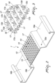
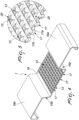
- the reference numeral 1 generally designates a profiled element with which plasterboard walls or panels 2 can be associated.
- the profiled element 1 can be constituted by one or more horizontal 3 or vertical 4 profiled elements, by one or more front posts 5, by one or more abutment posts 6, by one or more rear posts 7, by one or more horizontal crossmembers 8, by one or more upper crossmembers 9 for the rear posts 7, front posts 5 and abutment posts 6 and also by a support for a rail/guide (not shown) for sliding trolleys (not shown) with which sliding doors or leaves (not shown) are associated, all made of metal plate.
- a profiled element 1 in its various forms used to achieve the support/placement and/or the fastening of plasterboard panels 2 adapted to define the walls 10 of an in-wall frame 11 for doors or panels which can slide in-wall or which can be installed in frames for providing plasterboard walls.
- the upper crossmember 9 furthermore connects the abutment post 6 which is fixed to the opposite end from the rear post 7, and the front posts 5 are arranged approximately at the same distance between the rear posts 7 and the front posts 5.
- the rear posts 7 and the front posts 5 are transversely connected by the horizontal crossmembers 8 and are positioned at a vertical distance from each other such as to divide the length of the rear post 7 and front posts 5 into approximately identical parts.
- the method allows to obtain, starting from a metallic lamina, a profiled element 1 that has, in each one of its embodiments, the horizontal 3 or vertical 4 profiled element, the front post 5, the abutment post 6, the rear post 7, the horizontal crossmember 8, the upper crossmember 9, a planar surface 12 on which a plurality of holes 13 is provided, which are uniformly distributed according to a series of mutually parallel rows.
- the holes 13, which are through holes, can be obtained by way of a step of perforating the planar surface 12, which is obtained by way of punching or even by drawing, for example by way of a continuous machining which can be obtained by way of rolling and therefore using two rollers, one acting as a die (which determines the shape and the perforation of the metallic lamina so as to obtain the various holes 13), and the other acting as a punch (which determines the external shape of each one of the holes 13).
- the method also allows to obtain, for each horizontal crossmember 8 and at the longitudinal sides of the planar surface 12, one or more ridges or, as illustrated, two side edges or folds 15a, 15b and two wings 16a, 16b which give the horizontal crossmember 8 a substantially omega-like shape; such machining strengthens the profiled element and makes it less flexible.
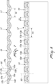
- the holes 13, which are obtained by deforming the planar surface 12, are distributed uniformly according to a series of mutually parallel rows, so as to obtain, between two adjacent rows, an upper surface 17 which thus delimits each distinct row of laterally adjacent holes 13 and is substantially shaped like an upturned U which determines a surface that is inclined in the direction of the adjacent holes 13 that are arranged at its sides.
- Each one of the holes 13 has, in plan view, a substantially conical shape 18 which provides a guide for the needle-like tip 50 of a fastening screw 51 to move toward the axis 52 of the corresponding hole 13 if the tip is arranged either on the upper surface 17 or at the side walls or surfaces (indicated in clockwise order) 13a, 13b, 17a, 13c, 13d and 17b of each hole 13 and of the upper surface 17.
- a perforated conical tab 20 protrudes, at each hole 13, at the lower surface 19 which is opposite the upper surface 17 and produces a localized increase in the thickness S of the planar surface 12.
- the holes 13 have, considering both the upper surface 17 and the lower surface 19, a substantially X-like shape.
- the side or diameter D1 of each one of the holes 13 that are present on the planar surface 12 of the profiled element 1, and therefore of each one of the horizontal profiled element 3, the vertical profiled element 4, the front post 5, the abutment post 6, the rear post 7, the horizontal crossmember 8, the upper crossmember 9, is equal to or smaller than three times the measure of the thickness S of the planar surface 12 that constitutes the profiled element 1 [D1 ⁇ 3S].
- the center distance D2 between two of the holes 13 that are mutually closer is equal to or greater than the thickness S of the profiled element 1 [D2 ⁇ S].
- the thickness S of the profiled element 1 is comprised between 0.4 and 1.5 millimeters [0.4 ⁇ S ⁇ 1.5].
- the presence and the particular arrangement of the holes 13 at the planar surface 12 enables an installation technician, once a plasterboard wall or panel 2 is placed alongside a profiled element 1, whether it is a horizontal 3 or vertical 4 profiled element, a front post 5, an abutment post 6, a rear post 7, a horizontal crossmember 8, an upper crossmember 9, to fasten it by positioning the screw in any point of the plasterboard wall or panel 2, making sure that the tip of that screw will intercept one of the holes 13 and therefore allows to achieve an optimal interconnection.
- the tip 50 of the screw 51 is positioned at an intermediate point between two adjacent holes 13 and therefore at the upper surface 17 i.e. when the displacement axis of the screw toward a hole 13 is greater, a minimal degree of offset is obtained in any case and, by virtue of both the curved shape of the upper surface 17 and the shape structure of the holes 13, the tip 50 is guided toward the hole 13.
- the head 53 of the screw 51 which has the characteristic trumpet shape, once screwed in, does not protrude from the surface of the panel 2 and does not break the surface layer/skin of the panel 2, thus ensuring a properly carried out fastening.
- the method has achieved the set aim and objects, by allowing to obtain a profiled element that allows to achieve the optimal and rapid support/placement and/or the fastening of plasterboard panels adapted to define the sides of an in-wall frame for doors or panels that slide in-wall, and which can be installed in frames for providing plasterboard walls, such profiled element having at the same time a considerable simplicity of construction and installation and allowing to obtain the fastening of normal plasterboard panels stably, durably and quickly.
- the needle-line tip 50 of the screws 51 for the plasterboard panels in fact, once in contact with the region of the planar surface 12 that has the holes 13, finds a guiding portion whatever its initial positioning; since the needle-like tip 50 of the screw 51 never finds a planar surface, it always slides into the holes 13, which are close together so as not to shift the axis of the screw too far and this is a great screwing advantage for the installation technician.
- the invention therefore resolves the problem of conveying the screw 51 to the nearest hole 13 to which its tip 50 is arranged, without such choice needing to be made by the installation technician, who has only to screw the screws 51 in any position, within the dimensions of the profiled element 1 underlying the panel that has the holes 13, without exerting particular pressure, and proceed until the head 53 of the screw 51 is flush with the surface of the panel 2; such operation is very light because high pressure is not needed to make a hole in the metal of the underlying profiled element 1.
- the profiled element 1 furthermore maintains particularly reduced thicknesses and allows to fasten plasterboard walls thereto even by people with no special training and with conventional or standard means for screwing that are easily available.
Landscapes
- Engineering & Computer Science (AREA)
- Architecture (AREA)
- Civil Engineering (AREA)
- Structural Engineering (AREA)
- Physics & Mathematics (AREA)
- Electromagnetism (AREA)
- Mechanical Engineering (AREA)
- Securing Of Glass Panes Or The Like (AREA)
- Finishing Walls (AREA)
- Load-Bearing And Curtain Walls (AREA)
- Panels For Use In Building Construction (AREA)
- Connection Of Plates (AREA)
Priority Applications (3)
| Application Number | Priority Date | Filing Date | Title |
|---|---|---|---|
| SI201830957T SI3775462T1 (sl) | 2018-03-29 | 2018-08-07 | Postopek za pridobitev navpičnega ali vodoravnega profiliranega elementa za medsebojno povezavo panelov iz mavčnih plošč in sten ter element, pridobljen s takim postopkom |
| HRP20230846TT HRP20230846T1 (hr) | 2018-03-29 | 2018-08-07 | Postupak za dobivanje vertikalnog ili horizontalnog profiliranog elementa za međuspajanje gipskartonskih ploča na zidove i element dobiven tim postupkom |
| RS20230690A RS64484B1 (sr) | 2018-03-29 | 2018-08-07 | Postupak dobijanјa vertikalnog ili horizontalnog profilnog elementa za međusobno vezivanje gipsanih panela za zidove i element dobijen takvim postupkom |
Applications Claiming Priority (2)
| Application Number | Priority Date | Filing Date | Title |
|---|---|---|---|
| IT102018000004060A IT201800004060A1 (it) | 2018-03-29 | 2018-03-29 | Metodo per l’ottenimento di un profilo verticale od orizzontale per la interconnessione a pareti in cartongesso ed il relativo metodo per il suo ottenimento |
| PCT/EP2018/071405 WO2019185176A1 (en) | 2018-03-29 | 2018-08-07 | Method for obtaining a vertical or horizontal profiled element for the interconnection of plasterboard panels to walls and element obtained with such method |
Publications (2)
| Publication Number | Publication Date |
|---|---|
| EP3775462A1 EP3775462A1 (en) | 2021-02-17 |
| EP3775462B1 true EP3775462B1 (en) | 2023-06-07 |
Family
ID=62597970
Family Applications (1)
| Application Number | Title | Priority Date | Filing Date |
|---|---|---|---|
| EP18752476.4A Active EP3775462B1 (en) | 2018-03-29 | 2018-08-07 | Method for obtaining a vertical or horizontal profiled element for the interconnection of plasterboard panels to walls and element obtained with such method |
Country Status (15)
| Country | Link |
|---|---|
| US (2) | US11499309B2 (pl) |
| EP (1) | EP3775462B1 (pl) |
| CA (1) | CA3096737A1 (pl) |
| DK (1) | DK3775462T3 (pl) |
| ES (1) | ES2950456T3 (pl) |
| FI (1) | FI3775462T3 (pl) |
| HR (1) | HRP20230846T1 (pl) |
| HU (1) | HUE062977T2 (pl) |
| IT (1) | IT201800004060A1 (pl) |
| LT (1) | LT3775462T (pl) |
| PL (1) | PL3775462T3 (pl) |
| RS (1) | RS64484B1 (pl) |
| RU (1) | RU2768299C1 (pl) |
| SI (1) | SI3775462T1 (pl) |
| WO (1) | WO2019185176A1 (pl) |
Families Citing this family (2)
| Publication number | Priority date | Publication date | Assignee | Title |
|---|---|---|---|---|
| IT201800004060A1 (it) | 2018-03-29 | 2019-09-29 | Eclisse Srl | Metodo per l’ottenimento di un profilo verticale od orizzontale per la interconnessione a pareti in cartongesso ed il relativo metodo per il suo ottenimento |
| GB2700096A (en) * | 2023-12-15 | 2025-09-24 | Autex Industries Ltd | Fixing of pet panels to allow for recycling |
Family Cites Families (18)
| Publication number | Priority date | Publication date | Assignee | Title |
|---|---|---|---|---|
| US600392A (en) * | 1898-03-08 | John odell whitenack | ||
| US2706315A (en) * | 1949-06-11 | 1955-04-19 | Manley R Price | Wall or ceiling treatment |
| US3243930A (en) * | 1962-05-29 | 1966-04-05 | Nat Gypsum Co | Corrugated sheet metal structural members |
| US4142663A (en) * | 1977-04-28 | 1979-03-06 | Kaiser Steel Corporation | Apparatus and method for making perforated tube |
| US4408427A (en) * | 1980-10-03 | 1983-10-11 | Donn Incorporated | Framing system for demountable walls or the like |
| US5620290A (en) * | 1995-08-23 | 1997-04-15 | Illinois Tool Works Inc. | Ground retainer |
| DE102006021556A1 (de) * | 2006-05-08 | 2007-07-26 | Richter-System Gmbh & Co Kg | Befestigungselement für Bauelemente des Trockenbaus und ein Verfahren zur Herstellung eines solchen Befestigungselements |
| US20090013633A1 (en) * | 2006-12-29 | 2009-01-15 | Gordon Aubuchon | Metal framing members |
| WO2008086818A1 (en) * | 2007-01-15 | 2008-07-24 | Knauf Insaat Ve Yapi Elemaniari Ve Ticaret A.S. | Profile element as carrier structure for the construction of walls |
| FR2915217B1 (fr) * | 2007-04-20 | 2009-07-10 | Imphy Alloys Sa | Structure pour le montage dans une paroi d'un batiment de batis destines a supporter des panneaux tels que des panneaux photovoltaiques |
| US20090223167A1 (en) * | 2008-02-28 | 2009-09-10 | Anderson Jeffrey A | Pierced drywall stud |
| RU2487220C2 (ru) * | 2009-05-18 | 2013-07-10 | Эрнест Р. Боднар | Открытая каркасная стойка с низкой теплопроводностью и гнездами для винтов |
| WO2011020093A2 (en) * | 2009-08-14 | 2011-02-17 | Dmfcwbs, Llc | Improved structural framing member |
| IT1395877B1 (it) * | 2009-09-11 | 2012-10-26 | S C S P A | Controtelaio modulare per porte scorrevoli a scomparsa e relativo kit e metodo di montaggio. |
| RU2463411C1 (ru) | 2011-05-03 | 2012-10-10 | Хонко Билдингз Интернэшнл, ЛТД | Здание (варианты) |
| ITTV20120057U1 (it) | 2012-12-11 | 2014-06-12 | Eclisse Srl | Orditura per pareti o lastre in cartongesso |
| US9234348B1 (en) * | 2014-08-26 | 2016-01-12 | Usg Interiors, Llc | Drywall to acoustical ceiling transition trims |
| IT201800004060A1 (it) * | 2018-03-29 | 2019-09-29 | Eclisse Srl | Metodo per l’ottenimento di un profilo verticale od orizzontale per la interconnessione a pareti in cartongesso ed il relativo metodo per il suo ottenimento |
-
2018
- 2018-03-29 IT IT102018000004060A patent/IT201800004060A1/it unknown
- 2018-08-07 CA CA3096737A patent/CA3096737A1/en active Pending
- 2018-08-07 RS RS20230690A patent/RS64484B1/sr unknown
- 2018-08-07 SI SI201830957T patent/SI3775462T1/sl unknown
- 2018-08-07 RU RU2020135312A patent/RU2768299C1/ru active
- 2018-08-07 HR HRP20230846TT patent/HRP20230846T1/hr unknown
- 2018-08-07 HU HUE18752476A patent/HUE062977T2/hu unknown
- 2018-08-07 PL PL18752476.4T patent/PL3775462T3/pl unknown
- 2018-08-07 US US17/042,601 patent/US11499309B2/en active Active
- 2018-08-07 FI FIEP18752476.4T patent/FI3775462T3/fi active
- 2018-08-07 DK DK18752476.4T patent/DK3775462T3/da active
- 2018-08-07 WO PCT/EP2018/071405 patent/WO2019185176A1/en not_active Ceased
- 2018-08-07 ES ES18752476T patent/ES2950456T3/es active Active
- 2018-08-07 EP EP18752476.4A patent/EP3775462B1/en active Active
- 2018-08-07 LT LTEPPCT/EP2018/071405T patent/LT3775462T/lt unknown
-
2021
- 2021-07-29 US US17/388,104 patent/US11761202B2/en active Active
Also Published As
| Publication number | Publication date |
|---|---|
| US20210095465A1 (en) | 2021-04-01 |
| RS64484B1 (sr) | 2023-09-29 |
| ES2950456T3 (es) | 2023-10-10 |
| EP3775462A1 (en) | 2021-02-17 |
| US11761202B2 (en) | 2023-09-19 |
| US20210355678A1 (en) | 2021-11-18 |
| RU2768299C1 (ru) | 2022-03-23 |
| IT201800004060A1 (it) | 2019-09-29 |
| LT3775462T (lt) | 2023-08-10 |
| WO2019185176A1 (en) | 2019-10-03 |
| PL3775462T3 (pl) | 2023-11-27 |
| US11499309B2 (en) | 2022-11-15 |
| DK3775462T3 (da) | 2023-06-26 |
| FI3775462T3 (fi) | 2023-09-04 |
| HUE062977T2 (hu) | 2023-12-28 |
| SI3775462T1 (sl) | 2023-09-29 |
| HRP20230846T1 (hr) | 2023-11-10 |
| CA3096737A1 (en) | 2019-10-03 |
Similar Documents
| Publication | Publication Date | Title |
|---|---|---|
| US11761202B2 (en) | Method for obtaining a vertical or horizontal profiled element for the interconnection of plasterboard panels to walls and element obtained with such method | |
| US5937600A (en) | Exterior wall system and drip channel | |
| US4631894A (en) | Hardware for panel doors | |
| CA2958693C (en) | Drywall to acoustical ceiling tiles transition trims | |
| EP3149264B1 (en) | Support frame for sliding door systems | |
| EP2615219A1 (en) | A kit of parts for mounting a window lining and method of providing a window lining using said kit of parts | |
| EP0078905B1 (de) | Umfassungszarge zur Verkleidung einer Wandöffnung für eine Tür oder dergleichen | |
| EP1396602A1 (en) | Fixing means and method | |
| WO2009034384A1 (en) | Adjustable noggings | |
| US20210246656A1 (en) | Self-spacing lap and panel siding | |
| WO2019185177A1 (en) | Method for obtaining a vertical or horizontal profile for interconnection to plasterboard walls | |
| AT516256A4 (de) | Zargenprofil für ein türelement in einem trennwandsystem | |
| EP1477621B1 (de) | Bausatz zur Herstellung einer Abgrenzung einer Gebäudedämmung zu einer Sockeldämmung | |
| DE202004003976U1 (de) | Sockelleiste | |
| DE19637454C2 (de) | Isoliertes Torgliederpaneel eines Sektionaltores | |
| KR100995415B1 (ko) | 문에 사용되는 장식판 고정 프레임 | |
| US6804916B2 (en) | Window and door sealing system and process | |
| CN219138800U (zh) | 一种方便安装的门窗结构 | |
| CN105971452B (zh) | 一种门窗扇的扇料中挺 | |
| CN220565930U (zh) | 木质门门套结构 | |
| DE102009016917B3 (de) | Montage-Hilfswerkzeug und Verfahren zur Montage von Bauplatten an eine Unterkonstruktion | |
| EP4715138A1 (en) | Attachment system and method for attaching panels to a façade, and a ventilation profile for such a system | |
| RU63397U1 (ru) | Перекрывающая профильная планка | |
| DE202004020824U1 (de) | Halteelement für Bekleidungsprofile und Befestigungswerkzeug hierfür | |
| CN116044877A (zh) | 一种膨胀钉胶套、膨胀钉组件、护墙板间距可调结构 |
Legal Events
| Date | Code | Title | Description |
|---|---|---|---|
| REG | Reference to a national code |
Ref country code: HR Ref legal event code: TUEP Ref document number: P20230846T Country of ref document: HR |
|
| STAA | Information on the status of an ep patent application or granted ep patent |
Free format text: STATUS: UNKNOWN |
|
| STAA | Information on the status of an ep patent application or granted ep patent |
Free format text: STATUS: THE INTERNATIONAL PUBLICATION HAS BEEN MADE |
|
| PUAI | Public reference made under article 153(3) epc to a published international application that has entered the european phase |
Free format text: ORIGINAL CODE: 0009012 |
|
| STAA | Information on the status of an ep patent application or granted ep patent |
Free format text: STATUS: REQUEST FOR EXAMINATION WAS MADE |
|
| 17P | Request for examination filed |
Effective date: 20201026 |
|
| AK | Designated contracting states |
Kind code of ref document: A1 Designated state(s): AL AT BE BG CH CY CZ DE DK EE ES FI FR GB GR HR HU IE IS IT LI LT LU LV MC MK MT NL NO PL PT RO RS SE SI SK SM TR |
|
| AX | Request for extension of the european patent |
Extension state: BA ME |
|
| DAV | Request for validation of the european patent (deleted) | ||
| DAX | Request for extension of the european patent (deleted) | ||
| GRAP | Despatch of communication of intention to grant a patent |
Free format text: ORIGINAL CODE: EPIDOSNIGR1 |
|
| STAA | Information on the status of an ep patent application or granted ep patent |
Free format text: STATUS: GRANT OF PATENT IS INTENDED |
|
| INTG | Intention to grant announced |
Effective date: 20221018 |
|
| GRAS | Grant fee paid |
Free format text: ORIGINAL CODE: EPIDOSNIGR3 |
|
| GRAA | (expected) grant |
Free format text: ORIGINAL CODE: 0009210 |
|
| STAA | Information on the status of an ep patent application or granted ep patent |
Free format text: STATUS: THE PATENT HAS BEEN GRANTED |
|
| AK | Designated contracting states |
Kind code of ref document: B1 Designated state(s): AL AT BE BG CH CY CZ DE DK EE ES FI FR GB GR HR HU IE IS IT LI LT LU LV MC MK MT NL NO PL PT RO RS SE SI SK SM TR |
|
| REG | Reference to a national code |
Ref country code: GB Ref legal event code: FG4D |
|
| REG | Reference to a national code |
Ref country code: CH Ref legal event code: EP Ref country code: AT Ref legal event code: REF Ref document number: 1575594 Country of ref document: AT Kind code of ref document: T Effective date: 20230615 |
|
| REG | Reference to a national code |
Ref country code: DK Ref legal event code: T3 Effective date: 20230620 |
|
| REG | Reference to a national code |
Ref country code: DE Ref legal event code: R096 Ref document number: 602018051111 Country of ref document: DE |
|
| REG | Reference to a national code |
Ref country code: SE Ref legal event code: TRGR |
|
| P01 | Opt-out of the competence of the unified patent court (upc) registered |
Effective date: 20230529 |
|
| REG | Reference to a national code |
Ref country code: NL Ref legal event code: FP |
|
| REG | Reference to a national code |
Ref country code: FI Ref legal event code: FGE |
|
| REG | Reference to a national code |
Ref country code: NO Ref legal event code: T2 Effective date: 20230607 |
|
| REG | Reference to a national code |
Ref country code: ES Ref legal event code: FG2A Ref document number: 2950456 Country of ref document: ES Kind code of ref document: T3 Effective date: 20231010 |
|
| REG | Reference to a national code |
Ref country code: HR Ref legal event code: ODRP Ref document number: P20230846T Country of ref document: HR Payment date: 20230802 Year of fee payment: 6 |
|
| REG | Reference to a national code |
Ref country code: SK Ref legal event code: T3 Ref document number: E 42206 Country of ref document: SK |
|
| REG | Reference to a national code |
Ref country code: GR Ref legal event code: EP Ref document number: 20230401425 Country of ref document: GR Effective date: 20231010 |
|
| REG | Reference to a national code |
Ref country code: HR Ref legal event code: T1PR Ref document number: P20230846 Country of ref document: HR |
|
| PG25 | Lapsed in a contracting state [announced via postgrant information from national office to epo] |
Ref country code: LV Free format text: LAPSE BECAUSE OF FAILURE TO SUBMIT A TRANSLATION OF THE DESCRIPTION OR TO PAY THE FEE WITHIN THE PRESCRIBED TIME-LIMIT Effective date: 20230607 |
|
| REG | Reference to a national code |
Ref country code: HU Ref legal event code: AG4A Ref document number: E062977 Country of ref document: HU |
|
| PG25 | Lapsed in a contracting state [announced via postgrant information from national office to epo] |
Ref country code: IS Free format text: LAPSE BECAUSE OF FAILURE TO SUBMIT A TRANSLATION OF THE DESCRIPTION OR TO PAY THE FEE WITHIN THE PRESCRIBED TIME-LIMIT Effective date: 20231007 |
|
| PG25 | Lapsed in a contracting state [announced via postgrant information from national office to epo] |
Ref country code: SM Free format text: LAPSE BECAUSE OF FAILURE TO SUBMIT A TRANSLATION OF THE DESCRIPTION OR TO PAY THE FEE WITHIN THE PRESCRIBED TIME-LIMIT Effective date: 20230607 Ref country code: PT Free format text: LAPSE BECAUSE OF FAILURE TO SUBMIT A TRANSLATION OF THE DESCRIPTION OR TO PAY THE FEE WITHIN THE PRESCRIBED TIME-LIMIT Effective date: 20231009 Ref country code: IS Free format text: LAPSE BECAUSE OF FAILURE TO SUBMIT A TRANSLATION OF THE DESCRIPTION OR TO PAY THE FEE WITHIN THE PRESCRIBED TIME-LIMIT Effective date: 20231007 Ref country code: EE Free format text: LAPSE BECAUSE OF FAILURE TO SUBMIT A TRANSLATION OF THE DESCRIPTION OR TO PAY THE FEE WITHIN THE PRESCRIBED TIME-LIMIT Effective date: 20230607 |
|
| REG | Reference to a national code |
Ref country code: DE Ref legal event code: R097 Ref document number: 602018051111 Country of ref document: DE |
|
| PG25 | Lapsed in a contracting state [announced via postgrant information from national office to epo] |
Ref country code: MC Free format text: LAPSE BECAUSE OF FAILURE TO SUBMIT A TRANSLATION OF THE DESCRIPTION OR TO PAY THE FEE WITHIN THE PRESCRIBED TIME-LIMIT Effective date: 20230607 |
|
| PG25 | Lapsed in a contracting state [announced via postgrant information from national office to epo] |
Ref country code: MC Free format text: LAPSE BECAUSE OF FAILURE TO SUBMIT A TRANSLATION OF THE DESCRIPTION OR TO PAY THE FEE WITHIN THE PRESCRIBED TIME-LIMIT Effective date: 20230607 |
|
| PLBE | No opposition filed within time limit |
Free format text: ORIGINAL CODE: 0009261 |
|
| STAA | Information on the status of an ep patent application or granted ep patent |
Free format text: STATUS: NO OPPOSITION FILED WITHIN TIME LIMIT |
|
| PG25 | Lapsed in a contracting state [announced via postgrant information from national office to epo] |
Ref country code: LU Free format text: LAPSE BECAUSE OF NON-PAYMENT OF DUE FEES Effective date: 20230807 |
|
| PG25 | Lapsed in a contracting state [announced via postgrant information from national office to epo] |
Ref country code: LU Free format text: LAPSE BECAUSE OF NON-PAYMENT OF DUE FEES Effective date: 20230807 |
|
| 26N | No opposition filed |
Effective date: 20240308 |
|
| REG | Reference to a national code |
Ref country code: HR Ref legal event code: ODRP Ref document number: P20230846 Country of ref document: HR Payment date: 20240801 Year of fee payment: 7 |
|
| PG25 | Lapsed in a contracting state [announced via postgrant information from national office to epo] |
Ref country code: BG Free format text: LAPSE BECAUSE OF FAILURE TO SUBMIT A TRANSLATION OF THE DESCRIPTION OR TO PAY THE FEE WITHIN THE PRESCRIBED TIME-LIMIT Effective date: 20230607 |
|
| REG | Reference to a national code |
Ref country code: AT Ref legal event code: UEP Ref document number: 1575594 Country of ref document: AT Kind code of ref document: T Effective date: 20230607 |
|
| PG25 | Lapsed in a contracting state [announced via postgrant information from national office to epo] |
Ref country code: BG Free format text: LAPSE BECAUSE OF FAILURE TO SUBMIT A TRANSLATION OF THE DESCRIPTION OR TO PAY THE FEE WITHIN THE PRESCRIBED TIME-LIMIT Effective date: 20230607 |
|
| PG25 | Lapsed in a contracting state [announced via postgrant information from national office to epo] |
Ref country code: CY Free format text: LAPSE BECAUSE OF FAILURE TO SUBMIT A TRANSLATION OF THE DESCRIPTION OR TO PAY THE FEE WITHIN THE PRESCRIBED TIME-LIMIT; INVALID AB INITIO Effective date: 20180807 |
|
| REG | Reference to a national code |
Ref country code: HR Ref legal event code: ODRP Ref document number: P20230846 Country of ref document: HR Payment date: 20250730 Year of fee payment: 8 |
|
| PGFP | Annual fee paid to national office [announced via postgrant information from national office to epo] |
Ref country code: NL Payment date: 20250807 Year of fee payment: 8 |
|
| PGFP | Annual fee paid to national office [announced via postgrant information from national office to epo] |
Ref country code: HU Payment date: 20250804 Year of fee payment: 8 |
|
| PGFP | Annual fee paid to national office [announced via postgrant information from national office to epo] |
Ref country code: ES Payment date: 20250901 Year of fee payment: 8 Ref country code: FI Payment date: 20250807 Year of fee payment: 8 |
|
| PGFP | Annual fee paid to national office [announced via postgrant information from national office to epo] |
Ref country code: LT Payment date: 20250714 Year of fee payment: 8 Ref country code: DE Payment date: 20250807 Year of fee payment: 8 Ref country code: DK Payment date: 20250808 Year of fee payment: 8 |
|
| PGFP | Annual fee paid to national office [announced via postgrant information from national office to epo] |
Ref country code: GR Payment date: 20250807 Year of fee payment: 8 Ref country code: NO Payment date: 20250808 Year of fee payment: 8 |
|
| PGFP | Annual fee paid to national office [announced via postgrant information from national office to epo] |
Ref country code: PL Payment date: 20250728 Year of fee payment: 8 Ref country code: IT Payment date: 20250620 Year of fee payment: 8 |
|
| PGFP | Annual fee paid to national office [announced via postgrant information from national office to epo] |
Ref country code: BE Payment date: 20250807 Year of fee payment: 8 Ref country code: GB Payment date: 20250721 Year of fee payment: 8 |
|
| PGFP | Annual fee paid to national office [announced via postgrant information from national office to epo] |
Ref country code: HR Payment date: 20250730 Year of fee payment: 8 |
|
| PGFP | Annual fee paid to national office [announced via postgrant information from national office to epo] |
Ref country code: AT Payment date: 20250807 Year of fee payment: 8 Ref country code: FR Payment date: 20250805 Year of fee payment: 8 |
|
| PGFP | Annual fee paid to national office [announced via postgrant information from national office to epo] |
Ref country code: CH Payment date: 20250901 Year of fee payment: 8 Ref country code: SE Payment date: 20250808 Year of fee payment: 8 |
|
| PGFP | Annual fee paid to national office [announced via postgrant information from national office to epo] |
Ref country code: IE Payment date: 20250827 Year of fee payment: 8 Ref country code: RS Payment date: 20250801 Year of fee payment: 8 Ref country code: CZ Payment date: 20250729 Year of fee payment: 8 |
|
| PGFP | Annual fee paid to national office [announced via postgrant information from national office to epo] |
Ref country code: RO Payment date: 20250805 Year of fee payment: 8 |
|
| PGFP | Annual fee paid to national office [announced via postgrant information from national office to epo] |
Ref country code: SK Payment date: 20250728 Year of fee payment: 8 |
|
| PGFP | Annual fee paid to national office [announced via postgrant information from national office to epo] |
Ref country code: SI Payment date: 20250728 Year of fee payment: 8 |
|
| PG25 | Lapsed in a contracting state [announced via postgrant information from national office to epo] |
Ref country code: TR Free format text: LAPSE BECAUSE OF FAILURE TO SUBMIT A TRANSLATION OF THE DESCRIPTION OR TO PAY THE FEE WITHIN THE PRESCRIBED TIME-LIMIT Effective date: 20230607 |