EP3774602B1 - Support-roll stand comprising a pivoting frame for a belt conveyor system - Google Patents
Support-roll stand comprising a pivoting frame for a belt conveyor system Download PDFInfo
- Publication number
- EP3774602B1 EP3774602B1 EP19709901.3A EP19709901A EP3774602B1 EP 3774602 B1 EP3774602 B1 EP 3774602B1 EP 19709901 A EP19709901 A EP 19709901A EP 3774602 B1 EP3774602 B1 EP 3774602B1
- Authority
- EP
- European Patent Office
- Prior art keywords
- support
- drive
- frame
- pivoting frame
- belt
- Prior art date
- Legal status (The legal status is an assumption and is not a legal conclusion. Google has not performed a legal analysis and makes no representation as to the accuracy of the status listed.)
- Active
Links
- 230000001360 synchronised effect Effects 0.000 claims description 3
- 238000013461 design Methods 0.000 description 16
- 230000000694 effects Effects 0.000 description 8
- 230000007246 mechanism Effects 0.000 description 7
- 239000011248 coating agent Substances 0.000 description 5
- 238000000576 coating method Methods 0.000 description 5
- 230000008901 benefit Effects 0.000 description 3
- 230000005540 biological transmission Effects 0.000 description 3
- 230000007613 environmental effect Effects 0.000 description 3
- 230000008859 change Effects 0.000 description 2
- 230000000052 comparative effect Effects 0.000 description 2
- 238000001816 cooling Methods 0.000 description 2
- 239000000463 material Substances 0.000 description 2
- 239000002184 metal Substances 0.000 description 2
- 238000000034 method Methods 0.000 description 2
- 239000003082 abrasive agent Substances 0.000 description 1
- 239000000919 ceramic Substances 0.000 description 1
- 238000006243 chemical reaction Methods 0.000 description 1
- 238000010276 construction Methods 0.000 description 1
- 230000001419 dependent effect Effects 0.000 description 1
- 239000000428 dust Substances 0.000 description 1
- 229920001971 elastomer Polymers 0.000 description 1
- 238000004519 manufacturing process Methods 0.000 description 1
- 238000005259 measurement Methods 0.000 description 1
- 238000005065 mining Methods 0.000 description 1
- 238000012986 modification Methods 0.000 description 1
- 230000004048 modification Effects 0.000 description 1
- 238000012544 monitoring process Methods 0.000 description 1
- 229920002635 polyurethane Polymers 0.000 description 1
- 239000004814 polyurethane Substances 0.000 description 1
- 230000008092 positive effect Effects 0.000 description 1
- 230000008569 process Effects 0.000 description 1
- 238000009420 retrofitting Methods 0.000 description 1
- 239000005060 rubber Substances 0.000 description 1
- 239000004576 sand Substances 0.000 description 1
- 230000008054 signal transmission Effects 0.000 description 1
- 239000000725 suspension Substances 0.000 description 1
- 238000004804 winding Methods 0.000 description 1
Images


Classifications
-
- B—PERFORMING OPERATIONS; TRANSPORTING
- B65—CONVEYING; PACKING; STORING; HANDLING THIN OR FILAMENTARY MATERIAL
- B65G—TRANSPORT OR STORAGE DEVICES, e.g. CONVEYORS FOR LOADING OR TIPPING, SHOP CONVEYOR SYSTEMS OR PNEUMATIC TUBE CONVEYORS
- B65G39/00—Rollers, e.g. drive rollers, or arrangements thereof incorporated in roller-ways or other types of mechanical conveyors
- B65G39/10—Arrangements of rollers
- B65G39/12—Arrangements of rollers mounted on framework
-
- B—PERFORMING OPERATIONS; TRANSPORTING
- B65—CONVEYING; PACKING; STORING; HANDLING THIN OR FILAMENTARY MATERIAL
- B65G—TRANSPORT OR STORAGE DEVICES, e.g. CONVEYORS FOR LOADING OR TIPPING, SHOP CONVEYOR SYSTEMS OR PNEUMATIC TUBE CONVEYORS
- B65G23/00—Driving gear for endless conveyors; Belt- or chain-tensioning arrangements
- B65G23/02—Belt- or chain-engaging elements
- B65G23/04—Drums, rollers, or wheels
- B65G23/08—Drums, rollers, or wheels with self-contained driving mechanisms, e.g. motors and associated gearing
-
- B—PERFORMING OPERATIONS; TRANSPORTING
- B65—CONVEYING; PACKING; STORING; HANDLING THIN OR FILAMENTARY MATERIAL
- B65G—TRANSPORT OR STORAGE DEVICES, e.g. CONVEYORS FOR LOADING OR TIPPING, SHOP CONVEYOR SYSTEMS OR PNEUMATIC TUBE CONVEYORS
- B65G23/00—Driving gear for endless conveyors; Belt- or chain-tensioning arrangements
- B65G23/32—Driving gear for endless conveyors; Belt- or chain-tensioning arrangements for effecting drive at two or more points spaced along the length of the conveyors
- B65G23/36—Driving gear for endless conveyors; Belt- or chain-tensioning arrangements for effecting drive at two or more points spaced along the length of the conveyors comprising two or more driving motors each coupled to a separate driving element, e.g. at either end of the conveyors
-
- B—PERFORMING OPERATIONS; TRANSPORTING
- B65—CONVEYING; PACKING; STORING; HANDLING THIN OR FILAMENTARY MATERIAL
- B65G—TRANSPORT OR STORAGE DEVICES, e.g. CONVEYORS FOR LOADING OR TIPPING, SHOP CONVEYOR SYSTEMS OR PNEUMATIC TUBE CONVEYORS
- B65G23/00—Driving gear for endless conveyors; Belt- or chain-tensioning arrangements
- B65G23/44—Belt or chain tensioning arrangements
Landscapes
- Engineering & Computer Science (AREA)
- Mechanical Engineering (AREA)
- Rollers For Roller Conveyors For Transfer (AREA)
- Structure Of Belt Conveyors (AREA)
Description
Die Erfindung betrifft ein für eine Förderbandanlage geeignetes, einen Schwenkrahmen aufweisendes Tragrollengestell nach dem Oberbegriff der Ansprüche 1 und 2.The invention relates to a support roller frame which is suitable for a conveyor belt system and has a pivoting frame, according to the preamble of
Ein derartiges Tragrollengestell ist aus der
Am Schwenkrahmen des bekannten Tragrollengestells befinden sich zwei Tragrollen, welche elektrisch angetrieben sein können. Insbesondere können die Tragrollen einen elektrischen Eigenantrieb aufweisen.There are two support rollers, which can be driven electrically, on the pivoting frame of the known support roller frame. In particular, the support rollers can have an electrical self-drive.
Mögliche Bauformen von Spannvorrichtungen für Förderbandanlagen sind zum Beispiel in den Dokumenten
Eine lange Förderbandanlage umfasst typischerweise mehrere Tragrollengestelle, welche hintereinander angeordnet sind. In den einzelnen Tragrollengestellen sind beispielsweise jeweils drei oder vier trogartig zueinander angeordnete Tragrollen drehbar gelagert. Ist eine Tragrolle angetrieben, so handelt es sich dabei um einen Zwischenantrieb der Förderbandanlage.A long conveyor belt system typically includes several carrier roller frames, which are arranged one behind the other. In the individual support roller frames, for example, three or four support rollers arranged trough-like relative to one another are rotatably mounted. If a roller is driven, it is an intermediate drive of the conveyor belt system.
Eine mögliche Bauform eines Tragrollenantriebs für eine Bandförderanlage ist in der
Die
In der
Ein möglicher Antrieb einer Rolle, welche zum Antrieb einer Förderbahn vorgesehen ist, ist in der
Eine weitere Antriebseinheit für eine Transportrolle ist in der
Aus der
Die
Ein Verfahren zum Betrieb einer Förderbandanlage mit verteilt angetriebenen Tragrollen ist in der
Ein in der
Ein Langstreckenförderer mit einem Förderband und mehreren Mitnahmebändern, das heißt Treibriemen, ist in der
Ein weiterer Zwischenantrieb für endlose Gurtförderbänder ist in der
Aus der
Der Erfindung liegt die Aufgabe zugrunde, ein gegenüber dem Stand der Technik weiterentwickeltes Tragrollengestell mit mindestens einer angetriebenen Rolle anzugeben, welches sich durch eine besonders hohe Robustheit bei zugleich kompaktem, montagefreundlichen Aufbau auszeichnet.The invention is based on the object of specifying a support roller frame which has been developed further than the prior art and has at least one driven roller, which is characterized by a particularly high degree of robustness and at the same time a compact, assembly-friendly design.
Diese Aufgabe wird erfindungsgemäß gelöst durch ein Tragrollengestell mit den Merkmalen des Anspruchs 1. Ebenso wird die Aufgabe gelöst durch ein Tragrollengestell mit den Merkmalen des Anspruchs 2. Das Tragrollengestell weist in an sich bekannter Grundkonzeption einen Schwenkrahmen auf, an welchem mindestens zwei Tragrollen, insbesondere genau zwei Tragrollen, gelagert sind, wobei zumindest eine dieser Tragrollen einen elektrischen Eigenantrieb aufweist. Optional weist das Tragrollengestell zusätzlich zwei den Schwenkrahmen flankierende, zum Schwenkrahmen geneigt angeordnete, nicht angetriebene seitliche Tragrollen auf. Die seitlichen Tragrollen bilden zusammen mit den am Schwenkrahmen gelagerten Tragrollen eine Trogform.This object is achieved according to the invention by a support roller frame with the features of
Erfindungsgemäß ist der elektrische Eigenantrieb der Tragrolle als getriebeloser Antrieb, das heißt als elektrischer Direktantrieb, ausgebildet. Unter einem elektrischen Direktantrieb wird ein Antrieb verstanden, bei welchem das angetriebene Teil, im vorliegenden Fall eine Tragrolle, drehfest mit dem Rotor des Elektromotors verbunden oder unmittelbar als Rotor des Elektromotors ausgebildet ist.According to the invention, the self-propelled electric drive of the support roller is designed as a gearless drive, ie as a direct electric drive. A direct electric drive is understood to mean a drive in which the driven part, in the present case a support roller, is connected in a rotationally fixed manner to the rotor of the electric motor or is designed directly as the rotor of the electric motor.
Zur Abgrenzung des Begriffs Direktantrieb gegenüber sonstigen, indirekten Antrieben, wird auf die
Im Fall des erfindungsgemäßen Tragrollengestells ist der getriebelose Antrieb, das heißt Direktantrieb, vorzugsweise in Form eines Außenläufermotors mit einem drehfest mit dem Mantel der Tragrolle verbundenen Hohlrotor ausgebildet, wobei der zugehörige Stator im Inneren der Tragrolle liegt. Beispielsweise handelt es sich bei dem getriebelosen Antrieb um einen permanentmagneterregten Direktantriebsmotor. Ein solcher Direktantriebsmotor bietet gute Möglichkeiten der Drehzahlregelung und zeichnet sich durch ein gutes Verhältnis zwischen beanspruchtem Bauraum und erzielbarem Drehmoment aus. Zudem ist keine Stromzuführung zu rotierenden Teilen notwendig. Unabhängig von der Bauart des Elektromotors sind durch den Entfall eines Getriebes gute Voraussetzungen für einen Tragrollenantrieb mit besonders hohem Wirkungsgrad gegeben.In the case of the support roller frame according to the invention, the gearless drive, i.e. direct drive, is preferably in the form of an external rotor motor with a hollow rotor non-rotatably connected to the casing of the support roller, with the associated stator being located inside the support roller. For example, the gearless drive is a permanent magnet excited direct drive motor. Such a direct drive motor offers good options for speed control and is characterized by a good relationship between the space required and the torque that can be achieved. In addition, no power supply to rotating parts is necessary. Regardless of the design of the electric motor, there are good prerequisites for a conveyor roller drive with a particularly high level of efficiency due to the omission of a gear.
Gemäß einer möglichen Ausgestaltung sind die am Schwenkrahmen angebrachten Tragrollen jeweils an Armen gelagert, welche schwenkbar an Seitenteilen des Schwenkrahmens angelenkt sind. Diese geometrische Gestaltung entspricht im Prinzip der aus der
Statt einer Lagerung der Tragrollen an schwenkbaren Armen ist auch eine Lagerung der Tragrollen an einem in sich starren oder an einem verstellbaren Schwenkrahmen, beispielsweise einem rechteckigen Rahmen mit verstellbarer Seitenlänge, möglich. Unabhängig von der Art der Anbringung der Tragrollen können die beiden im Schwenkrahmen gelagerten Tragrollen jeweils elektrisch direkt angetrieben und elektronisch miteinander synchronisiert sein. Das anzutreibende Förderband kann in diesem Fall direkt auf den Tragrollen aufliegen. Eine elektrische Synchronisation der Tragrollen bedeutet, dass eine separate Regelung der Tragrollen existiert, wobei die Regelungen voneinander abhängig sind. Auf diese Weise wird Schlupf beim Betrieb der Förderbandanlage vermieden. Jede angetriebene, in die Synchronisation mit vernetzter Steuerung eingebundene Tragrolle hat eine eingebaute Sensorik, was die Winkelstellung und/oder Winkeländerung der betreffenden Tragrolle betrifft.Instead of mounting the support rollers on pivotable arms, it is also possible to mount the support rollers on a pivot frame that is rigid in itself or on an adjustable pivot frame, for example a rectangular frame with an adjustable side length. Irrespective of the type of attachment of the support rollers, the two support rollers mounted in the swivel frame can each be electrically driven directly and electronically synchronized with one another. In this case, the conveyor belt to be driven can rest directly on the support rollers. An electrical synchronization of the support rollers means that there is a separate control of the support rollers, with the controls being dependent on one another. In this way, slippage during operation of the conveyor belt system is avoided. Each driven idler that is integrated into the synchronization with networked control has built-in sensors that determine the angular position and/or change in angle of the idler in question.
Die im Schwenkrahmen gelagerten Tragrollen sind von einem Antriebsgurt umschlungen. Das anzutreibende Förderband liegt auf dem Antriebsgurt auf. Ein Antrieb des Antriebsgurtes ist bereits mit einer einzigen angetriebenen Tragrolle möglich. Alternativ kann ein Antrieb beider Tragrollen vorgesehen sein, wobei in der beschriebenen Weise eine Synchronisation der Antriebe der einzelnen Tragrollen erfolgt.A drive belt wraps around the support rollers mounted in the swing frame. The conveyor belt to be driven lies on the drive belt. A drive of the drive belt is already possible with a single driven support roller. Alternatively, both support rollers can be driven, the drives of the individual support rollers being synchronized in the manner described.
Durch den um die Tragrollen gelegten Antriebsgurt ist die Kontaktfläche zum anzutreibenden Förderband im Vergleich zu einem Tragrollengestell, welches angetriebene Tragrollen aufweist, auf denen das Förderband direkt aufliegt, um ein Vielfaches vergrößert, was einen besonders hohen Leistungseintrag in das Förderband ermöglicht. Zudem begünstigt der große Umschlingungswinkel um die Tragrolle, das heißt der ausgedehnte Kontaktbereich zwischen Tragrolle und Antriebsgurt, einen hohen Leitungseintrag in das Förderband.Due to the drive belt placed around the idlers, the contact surface to the conveyor belt to be driven is increased many times over in comparison to an idler frame that has driven idlers on which the conveyor belt rests directly, which enables a particularly high power input into the conveyor belt. In addition, the large angle of wrap around the idler, i.e. the extensive contact area between the idler and the drive belt, a high level of cable entry into the conveyor belt.
Die vergrößerte Kraftübertragungsfläche hat bei verschiedensten Betriebszuständen enorme Vorteile gegenüber Antriebsvorrichtungen mit direktem Kontakt zwischen Tragrolle und Förderband. Beispielsweise wird beim Bandanlauf, insbesondere bei geringer oder fehlender Belastung des Förderbandes durch zu förderndes Gut, ein Durchrutschen mit hoher Zuverlässigkeit vermieden. Selbst unter ungünstigen Umgebungsbedingungen wie extrem tiefen Temperaturen, die die Flexibilität des Förderbandes deutlich herabsetzen, bleibt eine ausreichende Fähigkeit der Kraftübertragung zwischen dem Antriebsgurt und dem Förderband erhalten.The increased power transmission area has enormous advantages over drive devices with direct contact between the idler roller and the conveyor belt in a wide variety of operating conditions. For example, slipping is avoided with a high level of reliability when the belt starts up, especially when the conveyor belt is under little or no load from the material to be conveyed. Even under unfavorable environmental conditions such as extremely low temperatures, which significantly reduce the flexibility of the conveyor belt, sufficient power transmission capability between the drive belt and the conveyor belt is maintained.
Auch für das Abbremsen des Förderbandes, beispielsweise bei einer Notfallbremsung, ist das Tragrollengestell, welches großflächig, nämlich über einen Antriebsgurt, Kraft auf das Förderband überträgt, besonders gut geeignet. Auch bei einer Notfallbremsung ist es möglich, das gesamte Förderband dezentral über die Tragrollen abzubremsen. Im Vergleich zu herkömmlichen Förderbandanlagen sind aufgrund dieser dezentralen Bremsfunktion lediglich moderate Qualitätsanforderungen durch das Förderband zu erfüllen. Beim Bremsvorgang ist eine Energierückgewinnung durch die Direktantriebsmotoren realisierbar.The support roller frame, which transmits force to the conveyor belt over a large area, namely via a drive belt, is also particularly well suited for braking the conveyor belt, for example in the event of an emergency braking operation. Even in the event of an emergency braking, it is possible to decentrally brake the entire conveyor belt via the idlers. Compared to conventional conveyor belt systems, only moderate quality requirements have to be met by the conveyor belt due to this decentralized braking function. When braking, energy can be recovered using the direct drive motors.
Im Normalbetrieb der Förderbandanlage wirkt sich der Antriebsgurt durch den geringen bis fehlenden Schlupf verschleißmindernd auf das Förderband aus. Auch der Antriebsgurt selbst sowie die direkt angetriebenen Tragrollen, welche Antriebsleistung auf den Antriebsgurt übertragen, sind nur in geringem Maße Verschleiß ausgesetzt. Dies gilt auch bei betriebstypischen Belastungen, welche durch abrasives Material wie Sand oder Staub gegeben sein können. Insgesamt sind die Standzeiten sowohl des Förderbandes als auch des Tragrollenmantels im Vergleich zu konventionellen Lösungen deutlich gesteigert. Hierbei wirken sich insbesondere die geringen Flächenpressungen zwischen Antriebsgurt und Förderband sowie die aufgrund des großen Umschlingungswinkels ebenfalls reduzierten Flächenpressungen zwischen Tragrolle und Antriebsriemen, verglichen mit Flächenpressungen, welche zwischen einem Förderband und einer dieses unmittelbar antreibenden Tragrolle auftreten, positiv aus. Der großflächige Kontakt zwischen dem Antriebsgurt und dem Förderband sorgt zudem dafür, dass sich das Förderband im Bereich der Stützung und des Antriebs durch das Tragrollengestell lediglich geringfügig verformt, was eine nur geringe Walkarbeit sowohl im Fördergut als auch im Förderband sowie im Antriebsgurt bedeutet.In normal operation of the conveyor belt system, the drive belt has a wear-reducing effect on the conveyor belt due to the low to no slippage. The drive belt itself and the directly driven support rollers, which transmit drive power to the drive belt, are only exposed to a small degree of wear. This also applies to typical operational loads, which can be caused by abrasive material such as sand or dust. Overall, the service life of both the conveyor belt and the idler roller shell is significantly increased compared to conventional solutions. In particular, the low surface pressures between the drive belt and the conveyor belt as well as the surface pressures between the idler roller and the drive belt, which are also reduced due to the large angle of wrap, have an effect compared to Surface pressures, which occur between a conveyor belt and a support roller directly driving it, have a positive effect. The extensive contact between the drive belt and the conveyor belt also ensures that the conveyor belt is only slightly deformed in the area of the support and the drive by the idler frame, which means only little flexing work in the conveyed goods, in the conveyor belt and in the drive belt.
Grundsätzlich ist eine Beschichtung der Oberfläche der direkt angetriebenen Tragrolle möglich. Die Parameter einer solchen Beschichtung sind in Abhängigkeit des Kontaktes zwischen der Tragrolle und dem Antriebsgurt zu bestimmen. Da die Belastungen an dieser Stelle, wie erläutert, geringer als bei einem Kontakt zwischen Tragrolle und Förderband sind, ergeben sich entsprechend reduzierte Anforderungen an die Beschichtung, was sowohl einer rationellen Herstellung als auch einer hohen Standzeit zu Gute kommt. Als zur Beschichtung der Tragrolle geeignete Materialien sind beispielhaft Polyurethan, Gummi und Keramik zu nennen.In principle, it is possible to coat the surface of the directly driven support roller. The parameters of such a coating are to be determined depending on the contact between the idler roller and the drive belt. Since the loads at this point, as explained, are lower than when there is contact between the idler roller and the conveyor belt, there are correspondingly reduced demands on the coating, which benefits both rational production and a long service life. Examples of materials suitable for coating the support roller are polyurethane, rubber and ceramics.
Unabhängig vom Vorhandensein einer Beschichtung der Tragrolle ist deren Oberfläche in Abhängigkeit von den im Einzelfall auftretenden Belastungen, was sowohl mechanische Belastungen als auch umgebungsbedingte Einflüsse, beispielsweise durch Feuchtigkeit, einschließt, auszulegen. Die gegebenenfalls durch eine Beschichtung gebildete Oberfläche der Tragrolle kann beispielsweise glatt, rau, oder in definierter Weise strukturiert, zum Beispiel mit Noppen versehen, sein. Der prinzipielle Aufbau des elektrischen Direktantriebs der Tragrolle ist hiervon grundsätzlich unabhängig.Irrespective of the existence of a coating on the support roller, its surface must be designed depending on the loads occurring in the individual case, which includes both mechanical loads and environmental influences such as moisture. The surface of the support roller, which may be formed by a coating, can be smooth, rough or structured in a defined manner, for example provided with knobs. The basic structure of the electrical direct drive of the support roller is fundamentally independent of this.
Um den Antriebsgurt in Axialrichtung der angetriebenen Tragrollen, das heißt quer zur Förderrichtung des Förderbandes, zu führen, können die Mantelflächen der Tragrollen ballig geformt sein, was einen Selbstzentrierungseffekt ergibt. Zusätzlich oder statt einer solchen Selbstzentrierung ist eine Führung durch zusätzliche Führungsrollen möglich. Auch eine seitliche Führung des Antriebsgurtes durch Formelemente, beispielsweise Anlageschultern, am Tragrollenmantel ist möglich.In order to guide the drive belt in the axial direction of the driven support rollers, that is to say transversely to the conveying direction of the conveyor belt, the lateral surfaces of the support rollers can be crowned, which results in a self-centering effect. In addition to or instead of such self-centering, guidance by additional guide rollers is possible. It is also possible to guide the drive belt laterally by means of shaped elements, for example contact shoulders, on the support roller casing.
Die Spannung des um die Tragrollen gelegten Antriebsgurtes ist mit Hilfe verschiedener Mechanismen möglich:
Beispielsweise ist die effektive Seitenlänge des Schwenkrahmens verstellbar, um den Antriebsgurt auf Spannung zu halten. Sofern an den Seitenteilen des Schwenkrahmens Arme angelenkt sind, an welchen die Tragrollen gelagert sind, kann zum Beispiel die effektive Länge dieser Arme verstellbar sein. Ebenso ist eine Verstellvorrichtung unmittelbar in ein offenes Aufnahmeende eines starren Seitenteils, in welches eine Tragrolle einzuschieben ist, integrierbar, wobei die Rotationsachse der Tragrolle in frei wählbarer Position fixierbar ist.The tension of the drive belt placed around the idlers is possible with the help of various mechanisms:
For example, the effective side length of the swing frame is adjustable to keep the drive belt taut. If arms are articulated on the side parts of the swing frame, on which the support rollers are mounted, the effective length of these arms can be adjustable, for example. Likewise, an adjusting device can be integrated directly into an open receiving end of a rigid side part, into which a support roller is to be inserted, with the axis of rotation of the support roller being able to be fixed in a freely selectable position.
Allgemein werden Vorrichtungen, die dazu vorgesehen sind, den Antriebsgurt auf Spannung zu halten, als Gurtspannvorrichtungen bezeichnet. Hierunter fallen sowohl Vorrichtungen mit automatischer Nachspannung als auch Vorrichtungen, die eine Änderung der Einstellung durch den Benutzer erfordern. Eine einfache automatische Nachspannung ist zum Beispiel mittels einer federnden Lagerung von Rollen, im Extremfall bereits einer einzigen Rolle, realisierbar. Insbesondere kann eine Tragrolle federnd innerhalb des Tragrollengestells gelagert sein, wobei eine auf die Tragrolle wirkende Federkraft in Förderrichtung der Förderbandanlage ausgerichtet ist.Devices that are intended to keep the drive belt tensioned are generally referred to as belt tensioning devices. This includes both devices with automatic re-tensioning and devices that require the user to change the setting. A simple automatic re-tensioning can be implemented, for example, by means of a spring-loaded bearing of rollers, in extreme cases even a single roller. In particular, a support roller can be resiliently mounted within the support roller frame, with a spring force acting on the support roller being aligned in the conveying direction of the conveyor belt system.
In diversen Ausführungsformen, unter anderem in Bauformen, in welchen sich die Rotationsachsen der Tragrollen in festgelegter Position relativ zum Schwenkrahmen befinden, ist eine Einstellung der Spannung des Antriebsgurtes beispielsweise durch mindestens eine Spannrolle veränderbar. Die Spannrolle ist somit Teil der Gurtspannvorrichtung. Der Mechanismus, welcher die Position der Spannrolle in Relation zu nicht verstellbaren Teilen des Tragrollengestells verändert, um die Spannung des Antriebsgurtes zu variieren, wird allgemein als Rollenspannvorrichtung bezeichnet. Somit ist jede Art von Rollenspannvorrichtung definitionsgemäß Teil einer Gurtspannvorrichtung. Umgekehrt umfasst eine Gurtspannvorrichtung jedoch nicht notwendigerweise eine Rollenspannvorrichtung, da Gurtspannvorrichtungen auch, wie erwähnt, auch ohne Verwendung gesonderter Spannrollen aufgebaut sein können. Eine Rollenspannvorrichtung kann als manuell einstellbare oder automatische Spannvorrichtung ausgebildet sein.In various embodiments, including designs in which the axes of rotation of the support rollers are in a fixed position relative to the pivoting frame, the tension of the drive belt can be adjusted, for example, by at least one tension roller. The tensioning roller is therefore part of the belt tensioning device. The mechanism that changes the position of the idler pulley relative to non-adjustable parts of the idler frame to vary the tension of the drive belt is commonly referred to as an idler tensioner. Thus, by definition, any type of pulley tensioner is part of a belt tensioner. Conversely, however, a belt tensioning device does not necessarily include a roller tensioning device, since belt tensioning devices can also, as mentioned, also without one Can be constructed using separate idlers. A roll tensioning device can be designed as a manually adjustable or automatic tensioning device.
In besonders bevorzugter Ausgestaltung sind zwei Spannrollen als Komponenten einer Gurtspannvorrichtung jeweils neben der Schwenkachse des Schwenkrahmens, insbesondere spiegelbildlich zur Schwenkachse des Schwenkrahmens, angeordnet, wobei die Positionierung jeder Spannrolle variierbar ist. Die einzelnen Spannrollen können beispielsweise angefedert und/oder rastend fixierbar sein. Eine Führung des Antriebsgurtes wird optional durch Führungsscheiben an den Spannrollen unterstützt.In a particularly preferred embodiment, two tensioning rollers are arranged as components of a belt tensioning device each next to the pivot axis of the pivoting frame, in particular mirror-inverted to the pivoting axis of the pivoting frame, with the positioning of each tensioning roller being variable. The individual tensioning rollers can, for example, be spring-loaded and/or can be fixed in a latching manner. Guidance of the drive belt is optionally supported by guide washers on the tensioning rollers.
Der gesamte Schwenkrahmen kann höhenverstellbar sein, insbesondere in Form einer automatischen Höhenverstellung, womit die erforderliche Kontaktpressung zum anzutreibenden Förderband herstellbar oder einstellbar ist. Hierbei ist beispielsweise der Schwenkrahmen auf Schraubenfedern gelagert, welche auf einer Traverse angebracht sind. Diese Traverse ist zum Beispiel in ein Obertrumgestell einer Förderbandanlage einhängbar. Ebenso kann eine Höhenverstellung lediglich der Tragrollen vorgesehen sein. Dies kann entweder durch einen aktiven, beispielsweise elektromotorischen Verstellmechanismus oder durch einen passiven Mechanismus, insbesondere Federmechanismus, welcher zum Beispiel Drehstabfedern oder Schenkelfedern umfasst, erfolgen.The height of the entire swivel frame can be adjustable, in particular in the form of an automatic height adjustment, with which the required contact pressure with respect to the conveyor belt to be driven can be produced or adjusted. Here, for example, the pivoting frame is mounted on coil springs, which are mounted on a traverse. This traverse can be hung, for example, in an upper run frame of a conveyor belt system. A height adjustment of only the support rollers can also be provided. This can be done either by an active adjustment mechanism, for example an electric motor, or by a passive mechanism, in particular a spring mechanism, which includes, for example, torsion bar springs or torsion springs.
Sofern das Tragrollengestell zusätzlich zu den am Schwenkrahmen gelagerten Tragrollen weitere, seitliche Tragrollen umfasst, können die Rotationsachsen der insgesamt vier Tragrollen, nämlich zwei waagrecht, hintereinander angeordneten Tragrollen und zwei seitlichen, schräg gestellten Tragrollen, in unterschiedlicher Weise relativ zueinander verstellbar beziehungsweise fest positioniert sein:
Zum einen sind Bauformen realisierbar, bei welchen die waagrechten, am Schwenkrahmen gelagerten Tragrollen, von welchen mindestens eine elektrisch direkt angetrieben ist, samt Schwenkrahmen gegenüber einem auch als Standrahmen bezeichneten Gestell, in welchem die schräg gestellten Tragrollen gelagert sind, kippbar sind. Der Schwenkrahmen ist hierbei entweder mittig oder außermittig aufgehängt. Im letztgenannten Fall sind die Tragrollen, welche am Schwenkrahmen gelagert sind, nicht spiegelbildlich zur Schwenkachse angeordnet. Entsprechendes kann für die Spannrollen gelten. Durch eine solche asymmetrische Gestaltung sind Effekte, welche aus der Förderbandbewegungsrichtung resultieren, zumindest teilweise kompensierbar.If the idler frame includes further lateral idlers in addition to the idlers mounted on the pivoting frame, the axes of rotation of the total of four idlers, namely two horizontal idlers arranged one behind the other and two lateral idlers positioned at an angle, can be adjusted or fixed in different ways relative to each other:
On the one hand, designs can be realized in which the horizontal support rollers mounted on the swivel frame, of which at least one is electrically driven directly, together with the swivel frame, can be tilted in relation to a frame, also known as a stationary frame, in which the inclined support rollers are stored. The swing frame is here suspended either centrally or off-center. In the latter case, the support rollers, which are mounted on the swivel frame, are not arranged as a mirror image of the swivel axis. The same can apply to the tension rollers. Effects resulting from the direction of movement of the conveyor belt can be at least partially compensated for by such an asymmetrical design.
Zum anderen können vier oder mehr Tragrollen in der Art einer sogenannten Girlande miteinander gekoppelt sein. Zum technischen Hintergrund wird in diesem Zusammenhang auf das Dokument
Zwischen rotierenden und nicht rotierenden Teilen einer Tragrolle mit elektrischem Direktantrieb können Dichtungen prinzipiell bekannter Bauart eingesetzt sein. Entsprechendes gilt für Tragrollen ohne Antrieb. In diesem Zusammenhang wird beispielhaft auf das Dokument
Im Vergleich zu herkömmlichen, nicht angetriebenen Tragrollen hat der elektrische Direktantrieb keine Auswirkungen auf Breite und Durchmesser der im Tragrollengestell aufgenommenen, direkt angetriebenen Tragrollen. Die Kühlung des Direktantriebsmotors ist als passive Kühlung ausführbar. Auch eine erweiterte Sensorik zur Steuerung undCompared to conventional, non-driven idlers, the electric direct drive has no effect on the width and diameter of the directly driven idlers in the idler frame. The cooling of the direct drive motor can be implemented as passive cooling. Also an extended sensor system for control and
Überwachung des Direktantriebsmotors sowie der Lagerungen, insbesondere Wälzlagerungen, welche eine Drehzahl-, Temperatur- und Kraftmessung umfassen kann, ist innerhalb der Tragrolle integrierbar und damit sowohl raumsparend untergebracht als auch vor Umgebungseinflüssen geschützt.Monitoring of the direct drive motor and the bearings, in particular roller bearings, which can include speed, temperature and force measurement, can be integrated within the support roller and thus accommodated in a space-saving manner and also protected from environmental influences.
Das Tragrollengestell ist beispielsweise in ausgedehnten Förderbandanlagen im Über- oder Untertagebau einsetzbar. Durch eine Mehrzahl an Tragrollengestellen mit jeweils mindestens einer angetriebenen Tragrolle können zentrale Antriebsstationen von Förderbandanlagen ergänzt oder ersetzt werden. Bei vorhandenen Anlagen können im Sinne eines Anlagen-Retrofits Modifikationen, welche die Förderleistung deutlich erhöhen, durch das Nachrüsten von Schwenkrahmen mit angetriebenen Tragrollen vorgenommen werden.The support roller frame can be used, for example, in extensive conveyor belt systems in surface or underground mining. Central drive stations of conveyor belt systems can be supplemented or replaced by a plurality of support roller frames, each with at least one driven support roller. In the case of existing systems, modifications can be made in the sense of a system retrofit, which significantly increase the conveying capacity by retrofitting swivel frames with driven support rollers.
Tragrollengestelle mit direkt angetriebenen Tragrollen sind vorzugsweise mit solcher Leistung und Anzahl in eine Förderbandanlage integriert, dass eine Redundanz des Antriebs gegeben ist, das heißt die Funktionsfähigkeit der Anlage auch bei Ausfall des Antriebs oder der Antriebe eines einzelnen Tragrollengestells erhalten bleibt.Support roller frames with directly driven support rollers are preferably integrated into a conveyor belt system with such power and number that there is redundancy of the drive, i.e. the functionality of the system is maintained even if the drive or the drives of an individual support roller frame fail.
Durch die dezentrale Einspeisung von Leistung mittels direkt angetriebener Tragrollen, welche in Tragrollengestelle mit Schwenkrahmen integriert sind und die Kippbarkeit des Schwenkrahmens in keiner Weise beeinträchtigen, ist eine hohe Variabilität einer Förderbandanlage, insbesondere was Versetzen oder Verlängern der Anlage betrifft, gegeben, womit insgesamt - einschließlich Umbauphasen - eine sehr hohe Verfügbarkeit der Förderbandanlage erzielt wird.Due to the decentralized supply of power by means of directly driven idlers, which are integrated in idler frames with swivel frames and do not impair the tilting of the swivel frame in any way, there is a high degree of variability in a conveyor belt system, especially with regard to moving or extending the system, which means that overall - including conversion phases - a very high availability of the conveyor belt system is achieved.
Von besonderem Vorteil ist die Tatsache, dass eine Förderbandanlage mit gleichbleibendem Förderbandquerschnitt und unveränderter Förderbandqualität nachträglich verlängert werden kann. Der in Relation zur Ausdehnung der Förderbandanlage geringe Förderbandquerschnitt geht einher mit einer geringen Förderbandspannung, was geringe Kurvenradien innerhalb der Förderbandanlage ermöglicht.Of particular advantage is the fact that a conveyor belt system with the same conveyor belt cross section and unchanged conveyor belt quality can be subsequently extended. The conveyor belt cross-section, which is small in relation to the expansion of the conveyor belt system, goes hand in hand with a low conveyor belt tension, which enables small curve radii within the conveyor belt system.
Nachfolgend werden mehrere Ausführungsbeispiele der Erfindung sowie ein nicht beanspruchtes Vergleichsbeispiel anhand einer Zeichnung näher erläutert. Hierin zeigen, teils vereinfacht:
- Fig. 1
- ein nicht beanspruchtes Tragrollengestell in perspektivischer Ansicht,
- Fig. 2
- ein Ausführungsbeispiel eines Tragrollengestells in einer
Ansicht analog Figur 1 , - Fig. 3
- ein Detail des Tragrollengestells nach
Figur 2 , - Fig. 4
- ein Tragrollengestell mit Spannvorrichtung für einen Antriebsgurt,
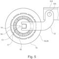
- Fig. 5
- in schematisierter Darstellung Komponenten eines Tragrollenantriebs.
- 1
- a non-claimed idler frame in a perspective view,
- 2
- an embodiment of a support roller frame in a view analogous
figure 1 , - 3
- a detail of the idler frame
figure 2 , - 4
- a roller frame with tensioning device for a drive belt,
- figure 5
- Schematic representation of the components of a conveyor roller drive.
Die folgenden Erläuterungen beziehen sich, soweit nicht anders angegeben, auf sämtliche Ausführungsbeispiele (
Ein insgesamt mit dem Bezugszeichen 1 gekennzeichnetes Tragrollengestell ist zum Antrieb eines lediglich in
Ein Standblech 2 bildet zusammen mit Halteblechen 3, 4 und weiteren fest mit dem Standblech 2 verbundenen Teilen einen Standrahmen 5, in welchem ein Schwenkrahmen 6 kippbar gelagert ist. Die entsprechende Schwenkachse ist mit SW bezeichnet. Grundsätzlich kann mit dem Schwenkrahmen 6 eine beliebige, in einer Förderbandanlage vorhandene Gestellform bestückt werden.A
Der Schwenkrahmen 6 hat eine rechteckige Grundform und weist zwei Seitenteile 7, 8 auf, welche in den Ausführungsbeispielen als U-Profile ausgeführt sind. Die Seitenteile 7, 8 sind durch Querstücke 9, 10, 11 miteinander verbunden, wobei die Mittelachse des Querstücks 10 mit der Schwenkachse SW zusammenfällt. An den Enden der Seitenteile 7, 8 sind diese in den Varianten nach den
Die Enden der Arme 12 sind als Gabelaufnahmen 14 ausgeführt, welche auch als Halteschlitze bezeichnet werden. In jedem Halteschlitz 14 ist ein Achsende 13 einer Tragrolle 20, 21 aufgenommen, welche direkt oder indirekt das Förderband 35 trägt. Die Achsenden 13 stellen die Naben der Tragrollen 20, 21 dar oder sind fest mit der Nabe der jeweiligen Tragrolle 20, 21 verbunden. Die Tragrollen 20, 21 sind damit am Schwenkrahmen 6 gelagert. In entsprechender Weise sind seitliche Tragrollen 22, 23 am Standrahmen 5 gelagert. Insgesamt wird damit durch das Tragrollengestell 1 eine Trogform, das heißt Muldenform, des Förderbandes 35 unterstützt.The ends of the
Das Tragrollengestell 1 ist nicht nur zur Führung, sondern auch zum Antrieb des Förderbandes 35 ausgebildet. Zu diesem Zweck ist mindestens eine der Tragrollen 20, 21 elektrisch angetrieben. Details dieses Antriebs, welcher für sämtliche Ausführungsbeispiele nach den
Das Achsende 13 und damit die gesamte Achse der Tragrolle 20, 21 ist fest mit einem Stator 16 eines Elektromotors verbunden. In dem in
Zwischen dem Rotor 19 und dem mit 15 bezeichneten Tragrollenmantel der Tragrolle 20 ist eine drehfeste Verbindung hergestellt, sodass der Tragrollenmantel 15 elektrisch direkt, das heißt getriebelos, angetrieben wird. Aufgrund der Gestaltung des Rotors 19 als permanentmagnetbestückter Außenläufer ist keine Stromzuführung zum Rotor 19 erforderlich. Der Tragrollenmantel 15 ist mittels nicht dargestellter Lager, insbesondere Wälzlager, gelagert. Eine gesonderte Lagerung des Rotors 19 ist nicht vorhanden.A non-rotatable connection is established between the rotor 19 and the idler roller shell, designated 15, of the
In der Bauform nach
Im Unterschied hierzu ist in den Ausgestaltungen nach den
Der Antriebsgurt 31 kann in Form einer leichten Gurtmuldung geführt sein, womit eine vergrößerte Kontaktfläche zum Förderband 35 hergestellt ist, was mit einer Übertragbarkeit größerer Kräfte einhergeht. Im Vergleich zu der in
Eine erste Möglichkeit, den Antriebsgurt 31 zu spannen, ist in
Ein der Energie- und Signalübertragung dienendes Kabel 28 ist mittig durch die Nabe 13 hindurch geführt und mit dem den Stator 16 sowie den Rotor 19 umfassenden, in
Im Unterschied zur Gestaltung nach
Rastkonturen 33, welche in
- 11
- Tragrollengestellidler frame
- 22
- Standblech, Querstrebestand plate, cross brace
- 33
- Halteblechretaining plate
- 44
- Halteblechretaining plate
- 55
- Standrahmenstand frame
- 66
- Schwenkrahmenswing frame
- 77
- Seitenteilside part
- 88th
- Seitenteilside part
- 99
- Querstückcrosspiece
- 1010
- Querstückcrosspiece
- 1111
- Querstückcrosspiece
- 1212
- Armpoor
- 1313
- Nabe, Achsendehub, axle end
- 1414
- Halteschlitz, GabelaufnahmeRetaining slot, fork mount
- 1515
- Tragrollenmantelidler roller cover
- 1616
- Statorstator
- 1717
- Wicklungwinding
- 1818
- Permanentmagnetpermanent magnet
- 1919
- Rotor, HohlrotorRotor, hollow rotor
- 2020
- Tragrollesupport roller
- 2121
- Tragrollesupport roller
- 2222
- Seitliche TragrolleLateral support roller
- 2323
- Seitliche TragrolleLateral support roller
- 2424
- Gewindestangethreaded rod
- 2525
- Einstellmutteradjusting nut
- 2626
- Halterung, BlechprofilBracket, sheet metal profile
- 2727
- Aufnahme, ringförmigRecording, ring-shaped
- 2828
- KabelCable
- 2929
- Verbindungselementfastener
- 3030
- Verbindungselementfastener
- 3131
- Antriebsgurtdrive belt
- 3232
- Spannrolleidler pulley
- 3333
- Rastkonturlocking contour
- 3434
- SeitenblechPage sheet
- 3535
- Förderbandconveyor belt
- 3636
- Gurtspannvorrichtungbelt tensioning device
- 3737
- Rollenspannvorrichtungroll tensioning device
- EAEA
-
Einstellachse, Schwenkachse des Arms 12Adjustment axis, pivot axis of the
arm 12 - SWSW
-
Schwenkachse des Schwenkrahmens 6Swivel axis of the
swivel frame 6 - TATA
-
Tragrollenachse, Rotationsachse der Tragrolle 20,21Support roller axis, axis of rotation of the
support roller
Claims (9)
- Support roll stand of a belt conveyor system, comprising a pivoting frame (6) on which at least two support rollers (20, 21) are mounted, wherein at least one of these support rolls (20, 21) has a dedicated electric drive, wherein the support rolls (20, 21) mounted on the pivoting frame (6) are each mounted on arms (12) which are pivotably hinged on side parts (7, 8) of the pivoting frame (6), characterized in that the dedicated electric drive is designed as a gearless drive (16, 19), wherein two support rolls (20, 21) which are mounted on the pivoting frame (6) and at least one of which is directly driven electrically, have a drive belt (31) wrapped therearound, the tension of which can be varied by means of a belt tensioning device (36), wherein the distance of the axis of rotation (TA) of a support roll (20, 21) from the pivot axis (EA) of the associated arms (12) is adjustable.
- The support roll stand of a belt conveyor system, comprising a pivoting frame (6) on which at least two support rollers (20, 21) are mounted, wherein at least one of these support rolls (20, 21) has a dedicated electric drive, characterized in that the dedicated electric drive is designed as a gearless drive (16, 19), wherein two support rolls (20, 21) mounted on the pivoting frame (6), at least one of which is electrically and directly driven, have a drive belt (31) wrapped therearound, the tension of which can be varied by means of a belt tensioning device (36) which comprises two tensioning rolls (32) which are arranged next to the pivot axis (SW) of the pivoting frame (6) in mirror image to the pivoting axis (SW) and the positioning of which can be varied in each case.
- The support roll stand according to claim 1 or 2, characterized in that the gearless drive (16, 19) is designed as an external-rotor motor with an internal stator (16) and a hollow rotor (19) connected to the shell of the support roll (20, 21) in a rotationally fixed manner.
- The support roll stand according to claim 3, characterized in that the gearless drive (16, 19) is designed as a permanent-magnet-excited direct-drive motor.
- The support roll stand according to any one of claims 1 to 4, characterized in that two support rolls (20, 21) mounted on the pivoting frame (6) are electrically and directly driven and electronically synchronized.
- A support roller stand according to any one of claims 1 to 4, characterized in that only one of the support rolls (20, 21) mounted on the pivoting frame (6) is electrically and directly driven.
- The support roll stand according to claim 2, characterized in that the positioning of each tensioning roll (32) can be varied by a roll tensioning device (37), in particular an automatic tensioning device, wherein the roll tensioning device (37) comprises two tensioning levers (33) hinged on the pivoting frame (6).
- The support roll stand according to any one of claims 1 to 7, characterized by two non-driven lateral support rolls (22, 23) which flank the pivoting frame (6) and are arranged at an angle to the pivoting frame (6).
- The support roll according to any one of claims 1 to 8, characterized in that the pivoting frame (6) is height-adjustable, in particular automatically height-adjustable, in relation to a base frame (5) tiltably supporting it.
Applications Claiming Priority (2)
| Application Number | Priority Date | Filing Date | Title |
|---|---|---|---|
| DE102018107127.2A DE102018107127B4 (en) | 2018-03-26 | 2018-03-26 | Support roller frame with swivel frame for a conveyor belt system |
| PCT/EP2019/055701 WO2019185322A1 (en) | 2018-03-26 | 2019-03-07 | Support-roll stand comprising a pivoting frame for a belt conveyor system |
Publications (2)
| Publication Number | Publication Date |
|---|---|
| EP3774602A1 EP3774602A1 (en) | 2021-02-17 |
| EP3774602B1 true EP3774602B1 (en) | 2023-08-30 |
Family
ID=65724398
Family Applications (1)
| Application Number | Title | Priority Date | Filing Date |
|---|---|---|---|
| EP19709901.3A Active EP3774602B1 (en) | 2018-03-26 | 2019-03-07 | Support-roll stand comprising a pivoting frame for a belt conveyor system |
Country Status (8)
| Country | Link |
|---|---|
| EP (1) | EP3774602B1 (en) |
| CN (1) | CN111741912B (en) |
| AU (1) | AU2019245717B2 (en) |
| BR (1) | BR112020016428A2 (en) |
| CL (1) | CL2020002072A1 (en) |
| DE (1) | DE102018107127B4 (en) |
| PE (1) | PE20210529A1 (en) |
| WO (1) | WO2019185322A1 (en) |
Family Cites Families (22)
| Publication number | Priority date | Publication date | Assignee | Title |
|---|---|---|---|---|
| DE1178359B (en) | 1962-08-02 | 1964-09-17 | Weserhuette Ag Eisenwerk | Intermediate drive with an endless drive belt for a long-distance conveyor |
| GB1088422A (en) | 1964-01-07 | 1967-10-25 | Solar Thomson Eng Co Ltd | Conveyor belt |
| US3407673A (en) * | 1966-05-19 | 1968-10-29 | Raymond J. Slezak | Belt tracking apparatus |
| DE2146218C3 (en) | 1971-09-16 | 1974-09-26 | Pohlig-Heckel-Bleichert Vereinigte Maschinenfabriken Ag, 5000 Koeln | Trough conveyor belt system |
| US3880275A (en) * | 1973-04-20 | 1975-04-29 | Hans Fischer | Trough belt conveyor |
| DE2643559A1 (en) | 1976-09-28 | 1978-03-30 | Eickhoff Geb | Endless conveyor belt intermediate drive - has drums on portal mountings straddling and guiding bottom run |
| GB2012700B (en) * | 1977-12-17 | 1982-05-12 | Ludwig Ing Buero Foerdertech | Belt conveyor |
| DE3724126C2 (en) | 1987-07-21 | 1995-04-13 | Telair Int Cargo Sys Gmbh | Drive roller unit |
| DE3903971C1 (en) * | 1989-02-10 | 1989-09-28 | Helmut Dipl.-Ing. 5162 Niederzier De Geppert | |
| DE20205428U1 (en) | 2002-04-09 | 2002-08-29 | Hupfer Metallwerke Gmbh & Co | Conveyor belt for commercial kitchens |
| DE20305351U1 (en) | 2003-04-02 | 2003-06-18 | Hese Gmbh Maschf Ernst | Drive belt/carrier belt drive system for belt conveyor with main drive unit consisting of three drive drums with drive belt passing over, and deflector drum |
| DE102006005158A1 (en) * | 2006-02-04 | 2007-08-16 | Abb Patent Gmbh | Drive drum of a belt conveyor and modular system for forming a drive drum |
| WO2013143550A1 (en) * | 2012-03-30 | 2013-10-03 | P. Ellegaard A/S | Hygienic drum motor |
| KR101388036B1 (en) * | 2013-01-31 | 2014-04-23 | 현대제철 주식회사 | Transferring apparatus for fuel and raw material |
| DE202013011823U1 (en) | 2013-08-02 | 2014-07-31 | Artur Küpper GmbH & Co. KG | Carrying roller garlands System |
| DE102014107591A1 (en) | 2014-05-28 | 2015-12-03 | Artur Küpper GmbH & Co. KG | Conveyor belt system with decentralized conveyor belt drive and method for operating the conveyor belt system |
| DE202015101778U1 (en) | 2014-08-21 | 2015-04-23 | Jiangxi Gongbu Machinery Co., Ltd. | External rotor motor |
| DE102014216733B4 (en) | 2014-08-22 | 2018-10-11 | Takraf Gmbh | Carrier roller drive for a belt conveyor |
| EP3034437B1 (en) | 2014-12-15 | 2018-10-31 | MTA Systems GmbH | Drive unit for a transport roller |
| DE102015115831A1 (en) | 2015-09-18 | 2017-03-23 | Artur Küpper GmbH & Co. KG | Carrying roller for a conveyor system |
| AU2016342298B2 (en) | 2015-10-20 | 2022-04-07 | Artur Küpper GmbH & Co. KG | Support roller rack having pivot frames and horizontal guiding and retaining slits |
| WO2017123534A1 (en) * | 2016-01-11 | 2017-07-20 | Therm-L-Tech Systems, LLC | Integrated direct drive motor system |
-
2018
- 2018-03-26 DE DE102018107127.2A patent/DE102018107127B4/en active Active
-
2019
- 2019-03-07 PE PE2020001204A patent/PE20210529A1/en unknown
- 2019-03-07 EP EP19709901.3A patent/EP3774602B1/en active Active
- 2019-03-07 BR BR112020016428-3A patent/BR112020016428A2/en active Search and Examination
- 2019-03-07 CN CN201980014230.4A patent/CN111741912B/en active Active
- 2019-03-07 AU AU2019245717A patent/AU2019245717B2/en active Active
- 2019-03-07 WO PCT/EP2019/055701 patent/WO2019185322A1/en unknown
-
2020
- 2020-08-10 CL CL2020002072A patent/CL2020002072A1/en unknown
Also Published As
| Publication number | Publication date |
|---|---|
| PE20210529A1 (en) | 2021-03-17 |
| BR112020016428A2 (en) | 2020-12-15 |
| CL2020002072A1 (en) | 2020-12-11 |
| AU2019245717B2 (en) | 2021-10-28 |
| DE102018107127A1 (en) | 2019-09-26 |
| EP3774602A1 (en) | 2021-02-17 |
| AU2019245717A1 (en) | 2020-10-08 |
| CN111741912A (en) | 2020-10-02 |
| CN111741912B (en) | 2022-03-29 |
| DE102018107127B4 (en) | 2024-03-07 |
| WO2019185322A1 (en) | 2019-10-03 |
Similar Documents
| Publication | Publication Date | Title |
|---|---|---|
| EP2250108B1 (en) | Apparatus and method for conveying piece goods, comprising a connectable driving device | |
| EP1700811A1 (en) | Elevator | |
| WO2009062734A1 (en) | Drive means and chain drive | |
| DE4428262C1 (en) | Motorized window regulator | |
| DE19510649C2 (en) | Transport device | |
| WO2012171616A1 (en) | Roller conveyor curve comprising round drive belts | |
| EP0534959A1 (en) | Take-up device for doubling roll-type reel cutters. | |
| EP3546399B1 (en) | Lifting and transport device and conveyor using the lifting and transport device | |
| EP3774602B1 (en) | Support-roll stand comprising a pivoting frame for a belt conveyor system | |
| EP0960842A1 (en) | Roller-conveyor with driven support rollers | |
| CH711696B1 (en) | Spinning or twisting machine with lifting spindle bench. | |
| DE60013439T2 (en) | CONVEYOR FOR CLOTHES | |
| EP0636559B1 (en) | Curved belt conveyor | |
| DE2843244A1 (en) | ROLLER MILL WITH TWO ROLLING STAND GROUPS IN A BLOCK FORM | |
| DE10117849C2 (en) | Spiral conveyor system | |
| CN1406850A (en) | Winder for forming reels | |
| EP2089305B1 (en) | Drive for lifts | |
| DE3905345A1 (en) | Device for frictionally driving an object, in particular a drum | |
| EP2437992B1 (en) | Conveying apparatus for transporting piece goods | |
| EP2785540B1 (en) | Coupling device | |
| DE102009027299A1 (en) | Drive device for driving leaf in sliding door system, has power transmission element transmitting driving power on leaf, and tensioning device tensioning transmission element and including automatically adjustable tensioning element | |
| EP0560102B1 (en) | Device for driving at its periphery a roll of web material | |
| DE4327860C1 (en) | Apparatus for the rotating mounting of a cable drum | |
| DE19715058A1 (en) | Drive device of a belt conveyor | |
| EP0359915B1 (en) | Drawing system for a spinning machine, in particular for a drawing frame |
Legal Events
| Date | Code | Title | Description |
|---|---|---|---|
| STAA | Information on the status of an ep patent application or granted ep patent |
Free format text: STATUS: UNKNOWN |
|
| STAA | Information on the status of an ep patent application or granted ep patent |
Free format text: STATUS: THE INTERNATIONAL PUBLICATION HAS BEEN MADE |
|
| PUAI | Public reference made under article 153(3) epc to a published international application that has entered the european phase |
Free format text: ORIGINAL CODE: 0009012 |
|
| STAA | Information on the status of an ep patent application or granted ep patent |
Free format text: STATUS: REQUEST FOR EXAMINATION WAS MADE |
|
| 17P | Request for examination filed |
Effective date: 20200914 |
|
| AK | Designated contracting states |
Kind code of ref document: A1 Designated state(s): AL AT BE BG CH CY CZ DE DK EE ES FI FR GB GR HR HU IE IS IT LI LT LU LV MC MK MT NL NO PL PT RO RS SE SI SK SM TR |
|
| AX | Request for extension of the european patent |
Extension state: BA ME |
|
| DAV | Request for validation of the european patent (deleted) | ||
| DAX | Request for extension of the european patent (deleted) | ||
| GRAP | Despatch of communication of intention to grant a patent |
Free format text: ORIGINAL CODE: EPIDOSNIGR1 |
|
| STAA | Information on the status of an ep patent application or granted ep patent |
Free format text: STATUS: GRANT OF PATENT IS INTENDED |
|
| INTG | Intention to grant announced |
Effective date: 20230601 |
|
| GRAS | Grant fee paid |
Free format text: ORIGINAL CODE: EPIDOSNIGR3 |
|
| GRAA | (expected) grant |
Free format text: ORIGINAL CODE: 0009210 |
|
| STAA | Information on the status of an ep patent application or granted ep patent |
Free format text: STATUS: THE PATENT HAS BEEN GRANTED |
|
| AK | Designated contracting states |
Kind code of ref document: B1 Designated state(s): AL AT BE BG CH CY CZ DE DK EE ES FI FR GB GR HR HU IE IS IT LI LT LU LV MC MK MT NL NO PL PT RO RS SE SI SK SM TR |
|
| REG | Reference to a national code |
Ref country code: GB Ref legal event code: FG4D Free format text: NOT ENGLISH |
|
| REG | Reference to a national code |
Ref country code: CH Ref legal event code: EP |
|
| REG | Reference to a national code |
Ref country code: DE Ref legal event code: R096 Ref document number: 502019009139 Country of ref document: DE |
|
| REG | Reference to a national code |
Ref country code: IE Ref legal event code: FG4D Free format text: LANGUAGE OF EP DOCUMENT: GERMAN |
|
| REG | Reference to a national code |
Ref country code: LT Ref legal event code: MG9D |
|
| REG | Reference to a national code |
Ref country code: NL Ref legal event code: MP Effective date: 20230830 |
|
| PG25 | Lapsed in a contracting state [announced via postgrant information from national office to epo] |
Ref country code: GR Free format text: LAPSE BECAUSE OF FAILURE TO SUBMIT A TRANSLATION OF THE DESCRIPTION OR TO PAY THE FEE WITHIN THE PRESCRIBED TIME-LIMIT Effective date: 20231201 |
|
| PG25 | Lapsed in a contracting state [announced via postgrant information from national office to epo] |
Ref country code: IS Free format text: LAPSE BECAUSE OF FAILURE TO SUBMIT A TRANSLATION OF THE DESCRIPTION OR TO PAY THE FEE WITHIN THE PRESCRIBED TIME-LIMIT Effective date: 20231230 |
|
| PG25 | Lapsed in a contracting state [announced via postgrant information from national office to epo] |
Ref country code: SE Free format text: LAPSE BECAUSE OF FAILURE TO SUBMIT A TRANSLATION OF THE DESCRIPTION OR TO PAY THE FEE WITHIN THE PRESCRIBED TIME-LIMIT Effective date: 20230830 Ref country code: RS Free format text: LAPSE BECAUSE OF FAILURE TO SUBMIT A TRANSLATION OF THE DESCRIPTION OR TO PAY THE FEE WITHIN THE PRESCRIBED TIME-LIMIT Effective date: 20230830 Ref country code: NO Free format text: LAPSE BECAUSE OF FAILURE TO SUBMIT A TRANSLATION OF THE DESCRIPTION OR TO PAY THE FEE WITHIN THE PRESCRIBED TIME-LIMIT Effective date: 20231130 Ref country code: LV Free format text: LAPSE BECAUSE OF FAILURE TO SUBMIT A TRANSLATION OF THE DESCRIPTION OR TO PAY THE FEE WITHIN THE PRESCRIBED TIME-LIMIT Effective date: 20230830 Ref country code: LT Free format text: LAPSE BECAUSE OF FAILURE TO SUBMIT A TRANSLATION OF THE DESCRIPTION OR TO PAY THE FEE WITHIN THE PRESCRIBED TIME-LIMIT Effective date: 20230830 Ref country code: IS Free format text: LAPSE BECAUSE OF FAILURE TO SUBMIT A TRANSLATION OF THE DESCRIPTION OR TO PAY THE FEE WITHIN THE PRESCRIBED TIME-LIMIT Effective date: 20231230 Ref country code: HR Free format text: LAPSE BECAUSE OF FAILURE TO SUBMIT A TRANSLATION OF THE DESCRIPTION OR TO PAY THE FEE WITHIN THE PRESCRIBED TIME-LIMIT Effective date: 20230830 Ref country code: GR Free format text: LAPSE BECAUSE OF FAILURE TO SUBMIT A TRANSLATION OF THE DESCRIPTION OR TO PAY THE FEE WITHIN THE PRESCRIBED TIME-LIMIT Effective date: 20231201 Ref country code: FI Free format text: LAPSE BECAUSE OF FAILURE TO SUBMIT A TRANSLATION OF THE DESCRIPTION OR TO PAY THE FEE WITHIN THE PRESCRIBED TIME-LIMIT Effective date: 20230830 |
|
| PG25 | Lapsed in a contracting state [announced via postgrant information from national office to epo] |
Ref country code: PL Free format text: LAPSE BECAUSE OF FAILURE TO SUBMIT A TRANSLATION OF THE DESCRIPTION OR TO PAY THE FEE WITHIN THE PRESCRIBED TIME-LIMIT Effective date: 20230830 Ref country code: NL Free format text: LAPSE BECAUSE OF FAILURE TO SUBMIT A TRANSLATION OF THE DESCRIPTION OR TO PAY THE FEE WITHIN THE PRESCRIBED TIME-LIMIT Effective date: 20230830 |
|
| PG25 | Lapsed in a contracting state [announced via postgrant information from national office to epo] |
Ref country code: ES Free format text: LAPSE BECAUSE OF FAILURE TO SUBMIT A TRANSLATION OF THE DESCRIPTION OR TO PAY THE FEE WITHIN THE PRESCRIBED TIME-LIMIT Effective date: 20230830 |
|
| PG25 | Lapsed in a contracting state [announced via postgrant information from national office to epo] |
Ref country code: SM Free format text: LAPSE BECAUSE OF FAILURE TO SUBMIT A TRANSLATION OF THE DESCRIPTION OR TO PAY THE FEE WITHIN THE PRESCRIBED TIME-LIMIT Effective date: 20230830 Ref country code: RO Free format text: LAPSE BECAUSE OF FAILURE TO SUBMIT A TRANSLATION OF THE DESCRIPTION OR TO PAY THE FEE WITHIN THE PRESCRIBED TIME-LIMIT Effective date: 20230830 Ref country code: ES Free format text: LAPSE BECAUSE OF FAILURE TO SUBMIT A TRANSLATION OF THE DESCRIPTION OR TO PAY THE FEE WITHIN THE PRESCRIBED TIME-LIMIT Effective date: 20230830 Ref country code: EE Free format text: LAPSE BECAUSE OF FAILURE TO SUBMIT A TRANSLATION OF THE DESCRIPTION OR TO PAY THE FEE WITHIN THE PRESCRIBED TIME-LIMIT Effective date: 20230830 Ref country code: DK Free format text: LAPSE BECAUSE OF FAILURE TO SUBMIT A TRANSLATION OF THE DESCRIPTION OR TO PAY THE FEE WITHIN THE PRESCRIBED TIME-LIMIT Effective date: 20230830 Ref country code: CZ Free format text: LAPSE BECAUSE OF FAILURE TO SUBMIT A TRANSLATION OF THE DESCRIPTION OR TO PAY THE FEE WITHIN THE PRESCRIBED TIME-LIMIT Effective date: 20230830 Ref country code: SK Free format text: LAPSE BECAUSE OF FAILURE TO SUBMIT A TRANSLATION OF THE DESCRIPTION OR TO PAY THE FEE WITHIN THE PRESCRIBED TIME-LIMIT Effective date: 20230830 Ref country code: PT Free format text: LAPSE BECAUSE OF FAILURE TO SUBMIT A TRANSLATION OF THE DESCRIPTION OR TO PAY THE FEE WITHIN THE PRESCRIBED TIME-LIMIT Effective date: 20240102 |
|
| PGFP | Annual fee paid to national office [announced via postgrant information from national office to epo] |
Ref country code: DE Payment date: 20240321 Year of fee payment: 6 |