EP3773975B1 - Vorrichtung und verfahren zum erfassen von verschleiss eines trennelements - Google Patents
Vorrichtung und verfahren zum erfassen von verschleiss eines trennelements Download PDFInfo
- Publication number
- EP3773975B1 EP3773975B1 EP19719166.1A EP19719166A EP3773975B1 EP 3773975 B1 EP3773975 B1 EP 3773975B1 EP 19719166 A EP19719166 A EP 19719166A EP 3773975 B1 EP3773975 B1 EP 3773975B1
- Authority
- EP
- European Patent Office
- Prior art keywords
- separating element
- rod
- coil
- sensor
- rotary pressure
- Prior art date
- Legal status (The legal status is an assumption and is not a legal conclusion. Google has not performed a legal analysis and makes no representation as to the accuracy of the status listed.)
- Active
Links
Images


Classifications
-
- B—PERFORMING OPERATIONS; TRANSPORTING
- B01—PHYSICAL OR CHEMICAL PROCESSES OR APPARATUS IN GENERAL
- B01D—SEPARATION
- B01D33/00—Filters with filtering elements which move during the filtering operation
- B01D33/06—Filters with filtering elements which move during the filtering operation with rotary cylindrical filtering surfaces, e.g. hollow drums
- B01D33/067—Construction of the filtering drums, e.g. mounting or sealing arrangements
-
- B—PERFORMING OPERATIONS; TRANSPORTING
- B01—PHYSICAL OR CHEMICAL PROCESSES OR APPARATUS IN GENERAL
- B01D—SEPARATION
- B01D33/00—Filters with filtering elements which move during the filtering operation
- B01D33/06—Filters with filtering elements which move during the filtering operation with rotary cylindrical filtering surfaces, e.g. hollow drums
- B01D33/073—Filters with filtering elements which move during the filtering operation with rotary cylindrical filtering surfaces, e.g. hollow drums arranged for inward flow filtration
-
- B—PERFORMING OPERATIONS; TRANSPORTING
- B01—PHYSICAL OR CHEMICAL PROCESSES OR APPARATUS IN GENERAL
- B01D—SEPARATION
- B01D33/00—Filters with filtering elements which move during the filtering operation
- B01D33/06—Filters with filtering elements which move during the filtering operation with rotary cylindrical filtering surfaces, e.g. hollow drums
- B01D33/073—Filters with filtering elements which move during the filtering operation with rotary cylindrical filtering surfaces, e.g. hollow drums arranged for inward flow filtration
- B01D33/09—Filters with filtering elements which move during the filtering operation with rotary cylindrical filtering surfaces, e.g. hollow drums arranged for inward flow filtration with surface cells independently connected to pressure distributors
-
- B—PERFORMING OPERATIONS; TRANSPORTING
- B01—PHYSICAL OR CHEMICAL PROCESSES OR APPARATUS IN GENERAL
- B01D—SEPARATION
- B01D33/00—Filters with filtering elements which move during the filtering operation
- B01D33/80—Accessories
- B01D33/804—Accessories integrally combined with devices for controlling the filtration
Definitions
- the present invention relates to a rotary pressure filter according to the preamble of claim 1.
- the suspension or the filter cake runs through various process zones, such as washing and drying zones, which are separated from one another in a gas-tight manner.
- So-called separating elements are usually provided for this separation, which extend from the housing through the process chamber to the filter drum and are pressed onto the filter drum with a predetermined pressure. As the filter drum moves under the separating elements which are stationary with respect to the housing and pressing on the filter drum, wear occurs on the separating elements.
- the separating elements are tracked accordingly in the direction of the filter drum. It is obvious that such tracking is only possible to a limited extent and the separating elements have to be replaced when a predetermined level of wear has been reached.
- this object is achieved according to the invention by a generic rotary pressure filter according to claim 1.
- one end of the rod can be attached to the separating element, in particular to a surface of the separating element pointing towards the sensor, and the other end of the rod can extend freely into the coil.
- the free end of the rod can, for example, in connection with a new separator to that of the end of the coil facing away from the separator or to the center of the coil.
- the separating elements can be made of a plastic, in particular a thermoplastic material with good sliding properties compared to steel running surfaces.
- the material can be selected depending on the conditions of use with regard to chemical resistance to the operating media and temperature resistance.
- the separating elements can be made of PE (UHMW), PA, PTFE, in particular PTFE with carbon/graphite, PVDF (advantageous, for example, in the case of increased chemical stress) or PEEK (advantageous, for example, at high temperatures).
- the displacement of the rod that is to say the tracking path of the separating element, and thus the wear of the separating element can be inferred from the current flowing through the electrically conductive material of the coil.
- the rod can be surrounded by a Teflon layer or another suitable layer which has a lower coefficient of friction than the material of the rod, in order to facilitate displacement of the rod in a bearing of the rod.
- the senor can also include a spring which prestresses the rod in the direction of the separating element.
- the spring can be arranged in such a way that it applies a corresponding force between the rod and a part of the housing, which forces the rod into Direction of the separating element urges.
- the spring can be designed as a compression spring.
- the compression spring can apply a spring force of, for example, 50 N to 160 N.
- the rod can be connected to a support element, which rests directly on the separating element or on a unit, for example a membrane, arranged between the separating element and the support element.
- the rod can be inserted into the support element, for example with the formation of a threaded engagement.
- the support element can have an enlarged surface, such as a plate-shaped section.
- a spring arranged on the sensor can act on the plate-shaped section of the support element instead of on the rod.
- the membrane arranged between the separating element and the housing can ensure that a gas seal between the process zones separated by the separating element is maintained, particularly in the case of a severely worn separating element that has been adjusted accordingly.
- the enlarged support surface of the support element can prevent the membrane from being damaged, in particular when it is arranged on a membrane.
- the rod can optionally be connected to one of a plurality of support elements, which differ in length, for example, in such a way that depending on the selection of the support element connected to the rod, an overall length of the combination of rod and support element can be varied .
- the sensor can be arranged in a section of the rotary pressure filter which is assigned to the same explosion hazard class as the process space of the rotary pressure filter is advantageously arranged within the process space of the rotary pressure filter or is in pressure-transmitting connection with it.
- the use of sensors in the process space of a rotary pressure filter is severely limited due to the regulations to be complied with regarding explosion safety and the special ambient conditions.
- the particularly simple structure of the sensor according to the invention allows it to be used in an environment in which high temperatures and/or high pressure and/or a high degree of pollution, for example due to solids contained in the air, prevail or prevail.
- An arrangement of the sensor in the process space of the rotary pressure filter can also simplify sealing of the housing of the rotary pressure filter.
- a moving sensor In the prior art, for example, a moving sensor must be guided from the separating element through the housing to an outside of the housing and correspondingly sealed in the housing, but still be movably mounted. This usually requires a great deal of effort in terms of construction, costs and/or approval. With the sensor according to the invention, only the current-carrying lines of the sensor can be routed through the housing, which can be easily sealed in the housing as non-moving parts.
- Typical ambient conditions in the process area of the rotary pressure filter are, for example, temperatures from 0°C to 120°C and pressures from 1-10 barg (at 0 barg pressure outside the housing).
- the process area of the rotary pressure filter is usually classified as an explosion hazard class or zone 0 at risk of explosion.
- the bar can be made of a magnetic material.
- the rod is made of a magnetizable or just metallic material.
- the measuring range of the sensor can detect a displacement of the rod by approximately 18 mm, in particular by approximately 22 mm.
- the separating elements of a rotary pressure filter according to the invention can therefore be designed to be shortened by about 18 mm from their original length due to wear. Once this degree of wear has been reached, the separating elements should be replaced with new ones.
- an oscillating circuit is applied to the coil, which is detuned when the rod is displaced in the coil.
- a characteristic of the resonant circuit that is present with a new separating element and thus with a rod initially arranged in the coil can be used as the standard state.
- a degree of displacement of the rod and therefore a corresponding displacement of the isolating element can thus be determined.
- Characteristics of the oscillating circuit which are associated with predetermined displacement positions of the rod or changes in these characteristics relative to one another can advantageously be stored in a memory unit. A current characteristic of the oscillating circuit can then be compared with a stored characteristic in order to determine a position or a displacement of the rod and thus of the separating element.
- the senor can be electrically connected to an evaluation unit, which is arranged outside a potentially explosive zone of the process space of the rotary pressure filter.
- the evaluation unit can include, for example, the memory unit mentioned above.
- a current or signal output by the coil of the sensor can be processed in the evaluation unit in such a way that displacement of the separating element and thus wear of the separating element can be determined.
- the arrangement of the evaluation unit Outside the potentially explosive zone of the process space of the rotary pressure filter can make it possible to use an evaluation unit which could not be available if the evaluation unit were arranged within the potentially explosive zone of the process space of the rotary pressure filter.
- the evaluation unit can be arranged in a non-explosive environment.
- a Zener barrier can prevent the ignitability of the circuit on the side of the zener barrier that includes the sensor.
- the present invention relates to a method for detecting wear of a separating element of a rotary pressure filter according to claim 9.
- the method for measuring a displacement of the rod and thus a displacement of the separating element is designed such that due to the displacement of the rod in the coil, current flows in the electrically conductive material from which the coil is formed or that an oscillating circuit is applied to the coil, which is detuned when the rod is moved in the coil.
- the senor can be connected to an evaluation unit, which can determine a displacement of the rod or the separating element on the basis of the measured current or the measured resonant circuit detuning.
- the evaluation unit can compare the measured current or the measured resonant circuit detuning with corresponding known values, which are stored, for example, in a memory unit of the evaluation unit, in order to be able to determine a displacement or a position of the rod and thus a displacement or wear of the separating element.
- the evaluation unit can output a signal which indicates a displacement of the separating element and/or a degree of wear of the separating element and/or a remaining wear distance of the separating element and/or a remaining operating time of the separating element and/or displays a notification regarding replacement of the separator.
- This signal can, for example, be output continuously to a display unit, which graphically and/or acoustically displays at least one of the above-mentioned information.
- the display unit can be activated and can, for example, output a warning signal to a user of the rotary pressure filter.
- the sensor structure according to the invention can also be used in other sections of the rotary pressure filter, such as for monitoring the filling level of a lubricant reservoir or for monitoring wear of a stuffing box packing.
- a rotary pressure filter according to the invention is generally designated 10 .
- the rotary pressure filter 10 includes a housing 12 which surrounds a filter drum and in which the filter drum is rotatably mounted.
- a process chamber 14 is formed between the filter drum and the housing 12 of the rotary pressure filter 10, in which the pressure is higher than on the outside of the housing 12.
- a sensor 16 is arranged at a passage opening of the housing 12 and comprises a coil 18 and a rod 20 arranged at least partially within the coil.
- the rod 20 is made here from a magnetizable metal.
- the rod 20 is movably mounted within the coil 18, in particular along a direction of the central axis of the coil 18 (see arrow A).
- the rod 20 is biased by a spring 22 in the direction of a membrane 24 in such a way that the rod 20 remains in contact with the membrane 24 even when the membrane 24 is displaced in the direction of the arrow A.
- the membrane 24 is on its side facing away from the rod 20 with a separating element 26 (see figure 3 ) in contact, which in turn presses on the filter drum of the rotary pressure filter.
- the opening of the housing 12 is sealed on the outside with a cover 28 which includes a pressure-resistant cable bushing 30 .
- An electrical conductor to which the coil 18 is connected can be led out of the housing through the pressure-resistant cable bushing 30 .
- the separating element 26 wears down, the side of the separating element 26 facing the sensor 16 and thus the membrane 24 are displaced away from it. Correspondingly, the rod 20 in the coil 18 shifted, so that in the coil 18, that is, in the electrically conductive material of the coil 18, current is induced. This current can be used as a basis for determining the displacement of the separating element 26 .
- FIG 2 a first embodiment of the sensor arrangement 16 is illustrated, which is based on FIG figure 1 described principle is based.
- an opening is provided in the housing 12 of the rotary pressure filter 10, in which the rod 20 is arranged.
- the coil 18 is positioned in a cylindrical extension of the cover 28 here.
- the pressure-resistant cable bushing 30 can be seen.
- the rod 20 according to the embodiment of FIG figure 2 is not formed in one piece, but comprises a support element 32 which engages with the rod 20 and which is connected to the membrane 24 on its side facing away from the rod 20 .
- the illustrated embodiment includes that end of the rod 20 which faces the membrane 24 and has a thread onto which a nut 34 is screwed.
- an immersion depth of the rod 20 in the support element 32 can be adjusted.
- Between the cover 28 and the support member 32 acts with reference to figure 1 described spring 22.
- an intermediate element 36 is arranged here between the housing 12 and the cover 28, which serves to increase the distance between the cover 28 and the membrane 24.
- the sensor 16 is screwed to the housing 12 by means of screws 38 through the cover 28 and the intermediate element 36 .
- figure 3 16 is a second embodiment of the sensor arrangement 16 according to FIG figure 2 shown, which differs from the embodiment according to figure 2 differs only slightly, so that analogous components are provided with the same reference numbers as in figure 2 , but increased by the number 100.
- FIG 3 is a sensor arrangement 116 or a sensor 16 on a
- the sensor arrangement 116 comprises a rod 120 which is mounted in a displaceable manner relative to a coil 118 .
- a spring 122 urges the rod 120 towards a diaphragm 124 which in turn is connected to the separator 26 in connection.
- a bearing element 132 which is designed here as a cylindrical disk, is connected to the rod 120.
- the support element 132 is screwed here to the rod 120 via a screw 140 .
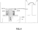
- the sensor arrangement 16 or 116 which is arranged on the housing 12 or 112 of the rotary pressure filter 10 or 110 and comprises a coil 18 or 118 and a rod 20 or 120, is shown only schematically.
- An evaluation unit 44 is electrically connected to the sensor 16 or 116 via a Zener barrier 42 .
- the evaluation unit 44 is located on the one hand due to the electrical interconnection of the Zener barrier 42 and on the other hand due to the spatial arrangement outside of the potentially explosive zone 1 in an area in which there is no risk of explosion and therefore no requirement for the explosion safety of the components located there.
- Evaluation unit 44 processes the signals output by sensor 16 or 116 and uses them to determine a displacement and/or wear of the corresponding separating element 26.
Landscapes
- Chemical & Material Sciences (AREA)
- Chemical Kinetics & Catalysis (AREA)
- Measuring Fluid Pressure (AREA)
- Filtering Of Dispersed Particles In Gases (AREA)
- Transmission And Conversion Of Sensor Element Output (AREA)
- Separation Using Semi-Permeable Membranes (AREA)
Description
- Die vorliegende Erfindung betrifft einen Druckdrehfilter nach dem Oberbegriff des Anspruchs 1.
- Die Anmelderin vertreibt seit vielen Jahren Druckfilter. Bei derartigen Druckdrehfiltern wird eine Suspension, welche ein Gemisch aus Flüssigkeit und Feststoffen ist, auf eine rotierende Filtertrommel aufgebracht. Die Filtertrommel ist derart ausgebildet, dass Flüssigkeit der Suspension durch eine Wandung der Filtertrommel hindurchtreten kann, wohingegen Feststoffe der Suspension an einer Oberfläche der Filtertrommel verbleiben. Folglich entsteht an der Oberfläche der Filtertrommel eine Feststoffschicht, welche in Fachkreisen als "Filterkuchen" bezeichnet wird.
- Die Suspension bzw. der Filterkuchen durchläuft verschiedene Prozesszonen, wie beispielsweise Wasch- und Trocknungszonen, welche voneinander gasdicht abgetrennt sind. Für diese Trennung sind üblicherweise sogenannte Trennelemente bereitgestellt, welche sich von dem Gehäuse durch den Prozessraum hindurch zu der Filtertrommel erstrecken und mit einem vorbestimmten Druck auf die Filtertrommel gepresst werden. Da sich die Filtertrommel unter den in Bezug auf das Gehäuse feststehenden und auf die Filtertrommel drückenden Trennelementen bewegt, entsteht an den Trennelementen Verschleiß.
- Um die Funktion der Trennelemente auch bei fortschreitendem Verschleiß zu gewährleisten, werden die Trennelemente in Richtung der Filtertrommel entsprechend nachgeführt. Es liegt auf der Hand, dass ein derartiges Nachführen nur begrenzt möglich ist und die Trennelemente bei Erreichen einer vorbestimmten Abnutzung ausgetauscht werden müssen.
- Bislang musste die Abnutzung der Trennelemente durch geschultes Personal nach Augenmaß überprüft werden oder es musste ein mechanischer Fühler abgelesen werden, welcher je nach Anordnung des Trennelements am Druckdrehfilter nur schwer zugänglich sein konnte.
- Aus dem Dokument
DE 196 54 165 C1 , welches als nächstliegender Stand der Technik erachtet wird, ist ein Druckdrehfilter bekannt, in welchem eine Filtertrommel in einem Gehäuse aufgenommen ist, wobei unter Verwendung eines Elektromagneten ein jeweiliges Trennelement gegen eine Federkraft zurückgezogen werden kann. Ferner sei auf die DokumenteWO 2009/061247 A1 undWO 2006/130093 A1 hingewiesen. - Es ist daher die Aufgabe der vorliegenden Erfindung, eine Vorrichtung und ein Verfahren zum Erfassen von Verschleiß eines Trennelements bereitzustellen, welche bzw. welches den Komfort und/oder die Genauigkeit des Ableseprozesses verbessert.
- In einem ersten Aspekt wird diese Aufgabe erfindungsgemäß durch einen gattungsgemäßen Druckdrehfilter nach Anspruch 1.
- Gemäß dem Induktionsprinzip wird in der Spule Strom erzeugt, wenn der Stab in der Spule verlagert wird. Dabei kann das eine Ende des Stabs an dem Trennelement, insbesondere an einer zu dem Sensor weisenden Fläche des Trennelements, angebracht sein und das andere Ende des Stabs kann sich frei in die Spule erstrecken. Das freie Ende des Stabs kann sich beispielsweise in Verbindung mit einem neuen Trennelement zu dem von dem Trennelement weg weisenden Ende der Spule oder bis zur Mitte der Spule erstrecken. Auf eine Abnutzung und ein Nachführen des Trennelements hin wird das freie Ende des Stabs in Richtung des zu dem Trennelement hin weisenden Endes der Spule verlagert.
- Die Trennelemente können aus einem Kunststoff, insbesondere aus einem thermoplastischen Kunststoff mit guten Gleiteigenschaften gegenüber Stahllaufflächen, hergestellt sein. Die Auswahl des Materials kann in Abhängigkeit der Einsatzbedingungen hinsichtlich chemischer Beständigkeit gegenüber den Betriebsmedien und Temperaturbeständigkeit erfolgen.
- Insbesondere können die Trennelemente aus PE (UHMW), PA, PTFE, insbesondere PTFE mit Kohle/Graphit, PVDF (beispielsweise vorteilhaft bei erhöhter chemischer Beanspruchung) oder PEEK (beispielsweise vorteilhaft bei hohen Temperaturen) gebildet sein.
- Über den durch das elektrisch leitfähige Material der Spule fließenden Strom kann auf die Verlagerung des Stabs, das heißt auf den Nachführungsweg des Trennelements, und somit auf den Verschleiß des Trennelements geschlossen werden.
- Der Stab kann dabei von einer Teflonschicht oder einer anderen geeigneten Schicht, welche einen geringeren Reibungskoeffizienten aufweist als das Material des Stabs, umgeben sein, um eine Verlagerung des Stabs in einer Lagerung des Stabs zu erleichtern.
- Um ein zuverlässiges Nachführen des Stabs gewährleisten zu können, insbesondere bei einer Anordnung, bei welcher ein Nachführen entgegen der Schwerkraft vorzunehmen ist, kann der Sensor ferner eine Feder umfassen, welche den Stab in Richtung des Trennelements vorspannt. Die Feder kann dabei derart angeordnet sein, dass die zwischen dem Stab und einem Teil des Gehäuses eine entsprechende Kraft aufbringt, welche den Stab in Richtung des Trennelements drängt. In diesem Fall kann die Feder als eine Druckfeder ausgeführt sein. Die Druckfeder kann entsprechend der Abnutzung des Trennelements eine Federkraft von beispielsweise 50 N bis 160 N aufbringen.
- In einer Weiterbildung der vorliegenden Erfindung kann der Stab mit einem Auflageelement in Verbindung stehen, welches direkt auf dem Trennelement oder einer zwischen dem Trennelement und dem Auflageelement angeordneten Einheit, beispielsweise einer Membran, aufliegt. Der Stab kann in das Auflageelement, zum Beispiel unter Ausbildung eines Gewindeeingriffs, eingeführt sein. An seinem zu dem Trennelement weisenden Ende kann das Auflageelement eine vergrößerte Fläche, wie beispielsweise einen tellerförmigen Abschnitt, aufweisen. Eine an dem Sensor angeordnete Feder kann hier, anstatt auf den Stab, auf den tellerförmigen Abschnitt des Auflageelements einwirken.
- Die zwischen dem Trennelement und dem Gehäuse angeordnete Membran kann gewährleisten, dass insbesondere bei einem stark abgenutzten und entsprechend nachgeführten Trennelement eine Gasabdichtung zwischen den durch das Trennelement getrennten Prozesszonen erhalten bleibt. Die vergrößerte Auflagefläche des Auflageelements kann insbesondere bei dessen Anordnung an einer Membran verhindern, dass die Membran beschädigt wird.
- Es ist ferner denkbar, dass der Stab wahlweise mit einem aus einer Mehrzahl von Auflageelementen verbunden werden kann, welche sich beispielsweise derart in einer Länge unterscheiden, dass je nach Wahl des mit dem Stab verbundenen Auflageelements eine Gesamtlänge der Kombination aus Stab und Auflageelement variiert werden kann.
- Der Sensor kann in einem Abschnitt des Druckdrehfilters angeordnet sein, welcher in der der gleichen Explosionsgefährdungsklasse zugeordnet ist wie der Prozessraum des Druckdrehfilters, vorteilhafterweise innerhalb des Prozessraums des Druckdrehfilters, angeordnet ist oder mit diesem in druckübertragender Verbindung steht. Üblicherweise ist der Einsatz von Sensoren in dem Prozessraum eines Druckdrehfilters aufgrund der einzuhaltenden Vorschriften bezüglich Explosionssicherheit und der besonderen Umgebungsbedingungen stark begrenzt. Der besonders einfache Aufbau des erfindungsgemäßen Sensors erlaubt jedoch dessen Einsatz in einer Umgebung, in der hohe Temperaturen und/oder hoher Druck und/oder ein hoher Verschmutzungsgrad, beispielsweise durch in der Luft enthaltene Feststoffe, herrscht bzw. herrschen. Eine Anordnung des Sensors im Prozessraum des Druckdrehfilters kann auch eine Abdichtung des Gehäuses des Druckdrehfilters vereinfachen. So muss beim Stand der Technik ein sich bewegender Fühler von dem Trennelement durch das Gehäuse hindurch zu einer Außenseite des Gehäuses geführt werden und entsprechend im Gehäuse abgedichtet, aber dennoch beweglich gelagert, sein. Dies erfordert üblicherweise einen hohen Aufwand bezüglich Konstruktion, Kosten und/oder Zulassung. Bei dem erfindungsgemäßen Sensor können lediglich die stromführenden Leitungen des Sensors durch das Gehäuse hindurch zu führen sein, welche als nicht bewegliche Teile einfach im Gehäuse abgedichtet werden können.
- Typische Umgebungsbedingungen im Prozessraum des Druckdrehfilters sind beispielsweise Temperaturen von 0°C bis 120°C und Drücke von 1-10 barg (bei 0 barg Druck außerhalb des Gehäuses). Der Prozessraum des Druckdrehfilters wird üblicherweise als Explosionsgefährdungsklasse bzw. als explosionsgefährdete Zone 0 eingestuft.
- Zur Unterstützung der Induktionswirkung des Stabs in der Spule kann der Stab aus einem magnetischen Material hergestellt sein. Natürlich ist es ebenfalls denkbar, dass der Stab aus einem magnetisierbaren oder lediglich metallischen Material hergestellt ist.
- In einer vorteilhaften Weiterbildung der Erfindung kann der Messbereich des Sensors eine Verlagerung des Stabs um etwa 18 mm, insbesondere um etwa 22 mm, erfassen. Die Trennelemente eines erfindungsgemäßen Druckdrehfilters können demnach dazu ausgelegt sein, von einer ursprünglichen Länge durch Abnutzung um etwa 18 mm verkürzt zu werden. Ist dieser Abnutzungsgrad erreicht, sollten die Trennelemente durch neue ersetzt werden. Um jedoch auch den Fall einer zu starken Abnutzung erfassen zu können, kann es vorteilhaft sein, den erfassbaren Messbereich des Sensors größer auszulegen als eine entsprechende maximale Abnutzung, das heißt Verkürzung, der Trennelemente. Dieser Sicherheitsbereich kann im Fall des hier beschriebenen Druckdrehfilters 4 mm oder generell etwa 4% bis 5% betragen.
- Erfindungsgemäß ist an die Spule ein Schwingkreis angelegt, welcher bei Verlagerung des Stabs in der Spule verstimmt wird. Zum Beispiel kann eine Charakteristik des Schwingkreises, welche bei einem neuen Trennelement und somit bei einem initial in der Spule angeordneten Stab vorliegt, als Normzustand verwendet werden. Auf Grundlage einer durch eine Verlagerung des Stabs innerhalb der Spule resultierenden Änderung der Charakteristik des Schwingkreises kann so ein Grad der Verlagerung des Stabs und daher eine entsprechende Verlagerung des Trennelements bestimmt werden. Vorteilhafterweise können Charakteristiken des Schwingkreises, welche vorbestimmten Verlagerungspositionen des Stabs zugehörig sind bzw. Änderungen dieser Charakteristiken zueinander in einer Speichereinheit gespeichert sein. Eine aktuelle Charakteristik des Schwingkreises kann dann mit einer gespeicherten Charakteristik verglichen werden, um eine Position bzw. eine Verlagerung des Stabs und somit des Trennelements zu bestimmen.
- Insbesondere für eine derartige Auswertung kann der Sensor mit einer Auswerteeinheit elektrisch verbunden sein, welche außerhalb einer explosionsgefährdeten Zone des Prozessraums des Druckdrehfilters angeordnet ist.
- Die Auswerteeinheit kann beispielsweise die voranstehend erwähnte Speichereinheit umfassen. Ein von der Spule des Sensors ausgegebener Strom bzw. ausgegebenes Signal kann in der Auswerteeinheit derart verarbeitet werden, dass eine Verlagerung des Trennelements und somit eine Abnutzung des Trennelements bestimmt werden kann. Die Anordnung der Auswerteeinheit außerhalb der explosionsgefährdeten Zone des Prozessraums des Druckdrehfilters kann es ermöglichen, eine Auswerteeinheit einzusetzen, welche bei einer Anordnung der Auswerteeinheit innerhalb der explosionsgefährdeten Zone des Prozessraums des Druckdrehfilters nicht zur Verfügung stehen könnte. Typischerweise kann die Auswerteeinheit so in einer nicht explosionsgefährdeten angeordnet sein.
- Zur Trennung des Sensors von der Auswerteeinheit kann es vorteilhaft sein, dass zwischen dem Sensor und der Auswerteeinheit eine Zenerbarriere angeordnet ist. Eine Zenerbarriere kann die Zündfähigkeit des Stromkreises auf der Seite der Zenerbarriere, welche den Sensor umfasst, verhindern.
- In einem zweiten Aspekt betrifft die vorliegende Erfindung ein Verfahren zum Erfassen von Verschleiß eines Trennelements eines Druckdrehfilters gemäß Anspruch 9.
- In Bezug auf die Vorteile und möglichen Ausgestaltungsformen des erfindungsgemäßen Verfahrens sei bereits an dieser Stelle auf die Ausführungen der erfindungsgemäßen Vorrichtung des Druckdrehfilters verwiesen.
- Gemäß der vorliegenden Erfindung ist das Verfahren zur Messung einer Verlagerung des Stabs und somit einer Verlagerung des Trennelements derart ausgebildet, dass auf Grund der Verlagerung des Stabs in der Spule in dem elektrisch leitfähigen Material, aus welchem die Spule gebildet ist, Strom fließt oder dass an die Spule ein Schwingkreis angelegt ist, welcher bei Verlagerung des Stabs in der Spule verstimmt wird.
- Auch diesbezüglich sei explizit auf die entsprechende Beschreibung des Druckdrehfilters verwiesen.
- Vorteilhafterweise kann der Sensor mit einer Auswerteeinheit verbunden sein, welche auf Grundlage des gemessenen Stroms oder der gemessenen Schwingkreis-Verstimmung eine Verlagerung des Stabs bzw. des Trennelements bestimmen kann. Die Auswerteeinheit kann dabei den gemessenen Strom oder die gemessene Schwingkreis-Verstimmung mit entsprechend bekannten Werten, welche beispielsweise in einer Speichereinheit der Auswerteeinheit gespeichert sind, vergleichen, um so eine Verlagerung bzw. eine Position des Stabs und somit eine Verlagerung bzw. eine Abnutzung des Trennelements bestimmen zu können.
- Dabei kann die Auswerteeinheit ein Signal ausgeben, welches eine Verlagerung des Trennelements und/oder einen Abnutzungsgrad des Trennelements und/oder einen verbleibenden Abnutzungsweg des Trennelements und/oder eine verbleibende Betriebszeit des Trennelements und/oder eine Mitteilung bezüglich eines Austauschs des Trennelements anzeigt. Dieses Signal kann beispielsweise kontinuierlich an eine Anzeigeeinheit ausgegeben werden, welche wenigstens eine der voranstehend genannten Informationen grafisch und/oder akustisch darstellt. Insbesondere bei Erreichen einer Abnutzung des Trennelements, bei welcher das Trennelement auszutauschen ist, kann die Anzeigeeinheit aktiviert werden und kann beispielsweise ein Warnsignal an einen Benutzer des Druckdrehfilters ausgeben.
- Es sei abschließend erwähnt, dass der erfindungsgemäße Sensoraufbau auch in anderen Abschnitten des Druckdrehfilters zum Einsatz kommen kann, wie beispielsweise zur Überwachung eines Füllstands eines Schmiermittel-Reservoirs oder zur Überwachung einer Abnutzung einer Stoffbuchspackung.
- Im Folgenden wird die Erfindung in größerem Detail anhand der begleitenden Zeichnungen beschrieben werden.
- Es stellt dar:
- Figur 1
- eine Seitenquerschnittsansicht einer schematischen Darstellung des Funktionsprinzips einer Sensoranordnung an einem Druckdrehfilter;
- Figur 2
- eine schematische Seitenquerschnittsansicht einer ersten Ausführungsform der Sensoranordnung an dem Druckdrehfilter;
- Figur 3
- eine schematische Seitenquerschnittsansicht einer zweiten Ausführungsform der Sensoranordnung an dem Druckdrehfilter; und
- Figur 4
- eine schematische Darstellung der Sensoranordnung und der Auswerteeinheit gemäß der vorliegenden Erfindung.
- In
Figur 1 ist ein erfindungsgemäßer Druckdrehfilter allgemein mit 10 bezeichnet. Der Druckdrehfilter 10 umfasst ein Gehäuse 12, welches eine Filtertrommel umgibt und in welcher die Filtertrommel drehbar gelagert ist. Zwischen der Filtertrommel und dem Gehäuse 12 des Druckdrehfilters 10 ist ein Prozessraum 14 gebildet, in welchem ein höherer Druck herrscht als an einer Außenseite des Gehäuses 12. - An einer Durchgangsöffnung des Gehäuses 12 ist ein Sensor 16 angeordnet, welcher eine Spule 18 und einen zumindest teilweise innerhalb der Spule angeordneten Stab 20 umfasst. Der Stab 20 ist hier aus einem magnetisierbaren Metall hergestellt.
- Der Stab 20 ist innerhalb der Spule 18, insbesondere entlang einer Richtung der Mittelachse der Spule 18 beweglich gelagert (siehe Pfeil A). Der Stab 20 wird von einer Feder 22 in Richtung einer Membran 24 derart vorgespannt, dass der Stab 20 auch bei einer Verlagerung der Membran 24 entlang der Richtung des Pfeils A mit dieser in Kontakt verbleibt. Die Membran 24 steht auf ihrer dem Stab 20 abgewandten Seite mit einem Trennelement 26 (siehe
Figur 3 ) in Kontakt, welches wiederum auf die Filtertrommel des Druckdrehfilters drückt. - Die Öffnung des Gehäuses 12 ist zu einer Außenseite hin mit einem Deckel 28 abgedichtet, welcher eine druckfeste Kabeldurchführung 30 umfasst. Durch die druckfeste Kabeldurchführung 30 hindurch kann ein elektrischer Leiter, mit welchem die Spule 18 verbunden ist, aus dem Gehäuse herausgeführt werden.
- Auf eine Abnutzung des Trennelements 26 hin wird die dem Sensor 16 zugewandte Seite des Trennelements 26 und somit die Membran 24 von diesem weg verlagert. Entsprechend wird der Stab 20 in der Spule 18 verlagert, so dass in der Spule 18, das heißt in dem elektrisch leitfähigen Material der Spule 18, Strom induziert wird. Dieser Strom kann als Grundlage einer Bestimmung der Verlagerung des Trennelements 26 dienen.
- In
Figur 2 ist eine erste Ausführungsform der Sensoranordnung 16 dargestellt, welche auf dem mit Bezug aufFigur 1 beschriebenen Prinzip basiert. Auch hier ist in dem Gehäuse 12 des Druckdrehfilters 10 eine Öffnung vorgesehen, in welcher der Stab 20 angeordnet ist. Die Spule 18 ist hier in einer zylinderförmigen Erweiterung des Deckels 28 positioniert. Am oberen rechten Ende derFigur 2 ist die druckfeste Kabeldurchführung 30 zu erkennen. - Im Gegensatz zu
Figur 1 ist der Stab 20 gemäß der Ausführungsform vonFigur 2 nicht einteilig ausgebildet, sondern umfasst ein mit dem Stab 20 in Eingriff stehendes Auflageelement 32, welches auf seiner dem Stab 20 abgewandten Seite mit der Membran 24 in Verbindung steht. In der inFigur 2 dargestellt Ausführungsform umfasst das der Membran 24 zugewandte Ende des Stabs 20 ein Gewinde auf welches eine Mutter 34 aufgeschraubt ist. Je nach Position der Mutter 34 auf dem Stab 20 kann eine Eintauchtiefe des Stabs 20 in das Auflageelement 32, und somit eine Gesamtlänge der Kombination aus Stab 20 und Auflageelement 32, eingestellt werden. Zwischen dem Deckel 28 und dem Auflageelement 32 wirkt die mit Bezug aufFigur 1 beschriebene Feder 22. - Aufgrund der Materialstärke des Gehäuses 12 ist hier zwischen dem Gehäuse 12 und dem Deckel 28 ein Zwischenelement 36 angeordnet, welches dazu dient, den Abstand zwischen dem Deckel 28 und der Membran 24 zu vergrößern.
- Durch den Deckel 28 und das Zwischenelement 36 hindurch ist der Sensor 16 mit dem Gehäuse 12 über Schrauben 38 verschraubt.
- Im Übrigen sei auf die Beschreibung mit Bezug auf
Figur 1 verwiesen. - In
Figur 3 ist eine zweite Ausführungsform der Sensoranordnung 16 gemäßFigur 2 dargestellt, welche sich von der Ausführungsform gemäßFigur 2 nur geringfügig unterscheidet, so dass analoge Bauteile mit gleichen Bezugszeichen versehen sind wie inFigur 2 , jedoch erhöht um die Zahl 100. - Bezüglich der Merkmale der Ausführungsform gemäß
Figur 3 sei bereits an dieser Stelle explizit auf die Beschreibungen bezüglich derFiguren 1 und2 verwiesen. - In
Figur 3 ist eine Sensoranordnung 116 bzw. ein Sensor 16 an einem - Gehäuse 112 eines Druckdrehfilters 110 angeordnet. Die Sensoranordnung 116 umfasst einen Stab 120, welcher relativ zu einer Spule 118 verlagerbar gelagert ist. Eine Feder 122 drängt den Stab 120 in Richtung einer Membran 124, welche wiederum mit dem Trennelement 26 in Verbindung steht.
- Als Auflagefläche zwischen dem Stab 120 und der Membran 124 ist mit dem Stab 120 ein Auflageelement 132, welches hier als zylinderförmige Scheibe ausgebildet ist, verbunden. Das Auflageelement 132 ist hier mit dem Stab 120 über eine Schraube 140 verschraubt.
- In
Figur 4 ist die an dem Gehäuse 12 bzw. 112 des Druckdrehfilters 10 bzw. 110 angeordnete Sensoranordnung 16 bzw. 116, welche eine Spule 18 bzw. 118 und einen Stab 20 bzw. 120 umfasst, lediglich schematisch dargestellt. - Der in dem Gehäuse 12 bzw. 112 angeordnete Bereich, das heißt der Prozessraum 14 bildet aufgrund der dort herrschenden Umgebungsbedingungen eine Explosionsgefährdungsklasse bzw. eine explosionsgefährdete Zone 0. Der den Außenbereich des Gehäuses 12 bzw. 112 direkt umgebende Bereich bildet eine explosionsgefährdete Zone 1 aus, da auch hier gelegentlich Umgebungsbedingungen auftreten können, in welchen Explosionsgefahr herrscht. Mit dem Sensor 16 bzw. 116 ist über eine Zenerbarriere 42 eine Auswerteeinheit 44 elektrisch verbunden. Die Auswerteeinheit 44 befindet sich einerseits aufgrund der elektrischen Zwischenschaltung der Zenerbarriere 42 und andererseits aufgrund der räumlichen Anordnung außerhalb der explosionsgefährdeten Zone 1 in einem Bereich, in welchem keine Explosionsgefährdung und somit keine Anforderung an die Explosionssicherheit der dort befindlichen Bauteile vorliegt. Die Auswerteeinheit 44 verarbeitet die von dem Sensor 16 bzw. 116 ausgegebenen Signale und bestimmt auf deren Basis eine Verlagerung und/oder einen Verschleiß des entsprechenden Trennelements 26.
Claims (11)
- Druckdrehfilter (10, 110), umfassendeine Filtertrommel, welche dazu eingerichtet ist, zu filtrierende Suspension zu filtern,ein Gehäuse (12, 112), welches die Filtertrommel umgibt und in welchem die Filtertrommel drehbar gelagert ist, wobei zwischen der Filtertrommel und dem Gehäuse (12, 112) ein Prozessraum (14) gebildet ist, undwenigstens ein Trennelement (26), welches derart zwischen dem Gehäuse (12, 112) und der Filtertrommel angeordnet ist, dass es den Prozessraum (14) in einer gasdichten Weise in eine Mehrzahl von Prozessabschnitten unterteilt,dadurch gekennzeichnet, dass an der dem Gehäuse (12, 112) zugewandten Seite wenigstens eines Trennelements (26) ein Sensor (16, 116) angeordnet ist, welcher Folgendes umfasst:eine unter Verwendung eines elektrisch leitfähigen Materials gebildete Spule (18, 118) undeinen aus einem Metall gebildeten Stab (20, 120), welcher innerhalb der Spule (18, 118) angeordnet ist,wobei der Stab (20, 120) dazu eingerichtet ist, auf Grundlage einer Abstandsänderung des Trennelements (26) relativ zu dem Sensor (16, 116) in der Spule (18, 118) verlagert zu werden, unddass an die Spule (18, 118) ein Schwingkreis angelegt ist, welcher bei Verlagerung des Stabs (20, 120) in der Spule (18, 118) verstimmt wird.
- Druckdrehfilter (10, 110) nach Anspruch 1,
dadurch gekennzeichnet, dass der Sensor (16, 116) ferner eine Feder (22, 122) umfasst, welche den Stab (20, 120) in Richtung des Trennelements (26) vorspannt. - Druckdrehfilter (10, 110) nach Anspruch 1 oder 2,
dadurch gekennzeichnet, dass der Stab (20, 120) mit einem Auflageelement (32, 132) in Verbindung steht, welches direkt auf dem Trennelement (26) oder einer zwischen dem Trennelement (26) und dem Auflageelement (32, 132) angeordneten Einheit (24, 124), beispielsweise einer Membran, aufliegt. - Druckdrehfilter (10, 110) nach einem der Ansprüche 1 bis 3,
dadurch gekennzeichnet, dass der Sensor (16, 116) in einem Abschnitt des Druckdrehfilters (10, 110) angeordnet ist, welcher der gleichen Explosionsgefährdungsklasse zugeordnet ist wie der Prozessraum (14) des Druckdrehfilters (10, 110), vorteilhafterweise innerhalb des Prozessraums (14) des Druckdrehfilters (10, 110) angeordnet ist oder mit diesem in druckübertragender Verbindung steht. - Druckdrehfilter (10, 110) nach einem der Ansprüche 1 bis 4,
dadurch gekennzeichnet, dass der Stab (20, 120) aus einem magnetischen Material hergestellt ist. - Druckdrehfilter (10, 110) nach einem der Ansprüche 1 bis 5,
dadurch gekennzeichnet, dass der Messbereich des Sensors (16, 116) eine Verlagerung des Stabs (20, 120) um etwa 18 mm, insbesondere um etwa 22 mm, erfasst. - Druckdrehfilter (10, 110) nach einem der Ansprüche 1 bis 6,
dadurch gekennzeichnet, dass der Sensor (16, 116) mit einer Auswerteeinheit (44) elektrisch verbunden ist, welche außerhalb einer explosionsgefährdeten Zone des Prozessraums (14) des Druckdrehfilters (10, 110) angeordnet ist. - Druckdrehfilter (10, 110) nach Anspruch 7,
dadurch gekennzeichnet, dass zwischen dem Sensor (16, 116) und der Auswerteeinheit (44) eine Zenerbarriere (42) angeordnet ist. - Verfahren zum Erfassen von Verschleiß eines Trennelements (26) eines Druckdrehfilters (10, 110), welchereine Filtertrommel, mittels welcher zu filtrierende Suspension gefiltert wird,ein Gehäuse (12, 112), welches die Filtertrommel umgibt und in welchem die Filtertrommel drehbar gelagert ist, wobei zwischen der Filtertrommel und dem Gehäuse (12, 112) ein Prozessraum (14) gebildet ist, undwenigstens ein Trennelement (26), welches derart zwischen dem Gehäuse (12, 112) und der Filtertrommel angeordnet ist, dass es den Prozessraum (14) in einer gasdichten Weise in eine Mehrzahl von Prozessabschnitten unterteilt, umfasst,dadurch gekennzeichnet, dass an der dem Gehäuse (12, 112) zugewandten Seite wenigstens eines Trennelements (26) ein Sensor (16, 116) angeordnet ist, welchereine unter Verwendung eines elektrisch leitfähigen Materials Spule (18, 118) undeinen aus einem Metall gebildeten Stab (20, 120), welcher innerhalb der Spule (18, 118) angeordnet ist, umfasst,wobei der Stab (20, 120), auf Grundlage einer Abstandsänderung des Trennelements (26) relativ zu dem Sensor (16, 116), in der Spule (18, 118) verlagert wird, und dass auf Grund der Verlagerung des Stabs (20, 120) in der Spule (18, 118) in dem elektrisch leitfähigen Material, aus welchem die Spule (18, 118) gebildet ist, Strom fließt oder dass an die Spule (18, 118) ein Schwingkreis angelegt ist, welcher bei Verlagerung des Stabs (20, 120) in der Spule (18, 118) verstimmt wird.
- Verfahren nach Anspruch 9,
dadurch gekennzeichnet, dass der Sensor (16, 116) mit einer Auswerteeinheit (44) verbunden ist, welche auf Grundlage des gemessenen Stroms oder der gemessenen Schwingkreis-Verstimmung eine Verlagerung des Stabs (20, 120) bzw. des Trennelements (26) bestimmt. - Verfahren nach Anspruch 10,
dadurch gekennzeichnet, dass die Auswerteeinheit (44) ein Signal ausgibt, welches eine Verlagerung des Trennelements (26) und/oder einen Abnutzungsgrad des Trennelements (26) und/oder einen verbleibenden Abnutzungsweg des Trennelements (26) und/oder eine verbleibende Betriebszeit des Trennelements (26) und/oder eine Mitteilung bezüglich eines Austauschs des Trennelements (26) anzeigt.
Applications Claiming Priority (2)
| Application Number | Priority Date | Filing Date | Title |
|---|---|---|---|
| DE102018205237.9A DE102018205237A1 (de) | 2018-04-06 | 2018-04-06 | Vorrichtung und Verfahren zum Erfassen von Verschleiß eines Trennelements |
| PCT/EP2019/058283 WO2019193001A1 (de) | 2018-04-06 | 2019-04-02 | VORRICHTUNG UND VERFAHREN ZUM ERFASSEN VON VERSCHLEIß EINES TRENNELEMENTS |
Publications (2)
| Publication Number | Publication Date |
|---|---|
| EP3773975A1 EP3773975A1 (de) | 2021-02-17 |
| EP3773975B1 true EP3773975B1 (de) | 2022-06-22 |
Family
ID=66251718
Family Applications (1)
| Application Number | Title | Priority Date | Filing Date |
|---|---|---|---|
| EP19719166.1A Active EP3773975B1 (de) | 2018-04-06 | 2019-04-02 | Vorrichtung und verfahren zum erfassen von verschleiss eines trennelements |
Country Status (7)
| Country | Link |
|---|---|
| US (1) | US11701604B2 (de) |
| EP (1) | EP3773975B1 (de) |
| KR (1) | KR20200139672A (de) |
| CN (1) | CN112055608B (de) |
| DE (1) | DE102018205237A1 (de) |
| ES (1) | ES2923525T3 (de) |
| WO (1) | WO2019193001A1 (de) |
Families Citing this family (1)
| Publication number | Priority date | Publication date | Assignee | Title |
|---|---|---|---|---|
| DE102018218907A1 (de) | 2018-11-06 | 2020-05-07 | Bhs-Sonthofen Gmbh | Druckdrehfiltermodul |
Family Cites Families (13)
| Publication number | Priority date | Publication date | Assignee | Title |
|---|---|---|---|---|
| DE244877C (de) * | ||||
| US2899068A (en) * | 1959-08-11 | Pressure | ||
| US2741369A (en) * | 1953-05-22 | 1956-04-10 | Appbau G M B H Fa | Rotary filters |
| DE1160603B (de) * | 1961-02-03 | 1964-01-02 | Guenther Missbach Dipl Ing | Vorrichtung zum kontinuierlichen Behandeln von folienartigen, bahnfoermigen Werkstoffen, insbesondere von Kunststoffolien |
| US5489383A (en) * | 1993-06-16 | 1996-02-06 | Hitachi Zosen Corporation | Screw type dewatering machine |
| DE19654165C1 (de) * | 1996-12-23 | 1998-08-27 | Bhs Sonthofen Maschinen & Anlagenbau Gmbh | Vorrichtung zur zyklischen Behandlung von Suspensionen |
| DE10239820A1 (de) * | 2002-08-29 | 2004-03-18 | Bhs-Sonthofen Maschinen- Und Anlagenbau Gmbh | Zerkleinerungsvorrichtung |
| SE528727C2 (sv) * | 2005-06-03 | 2007-02-06 | Metso Paper Inc | Anordning för behandling av cellulosamassa i en tvättapparat anordnad med medel för att avlägsna tätningar |
| SE531687C2 (sv) * | 2007-11-09 | 2009-07-07 | Metso Paper Inc | Metod och enhet för tätningsjustering i en tvättanordning samt tvättanordning innefattande enhet för tätningsjustering |
| CN202460268U (zh) * | 2011-06-29 | 2012-10-03 | 杭州化工机械有限公司 | 一种加压转鼓过滤机的区间密封结构 |
| CN104759465B (zh) * | 2015-04-15 | 2017-07-28 | 上田环境修复股份有限公司 | 一种具有粉碎功能的用于土壤修复的装置 |
| CN205731438U (zh) * | 2016-01-29 | 2016-11-30 | Bhs桑托芬有限公司 | 离心式破碎机设备 |
| CN107008042B (zh) * | 2017-06-03 | 2023-01-17 | 苏州城投环境科技发展有限公司 | 基于电磁力的污水污泥减量化脱水装置 |
-
2018
- 2018-04-06 DE DE102018205237.9A patent/DE102018205237A1/de not_active Withdrawn
-
2019
- 2019-04-02 ES ES19719166T patent/ES2923525T3/es active Active
- 2019-04-02 KR KR1020207025932A patent/KR20200139672A/ko not_active Withdrawn
- 2019-04-02 US US17/045,744 patent/US11701604B2/en active Active
- 2019-04-02 CN CN201980024354.0A patent/CN112055608B/zh active Active
- 2019-04-02 EP EP19719166.1A patent/EP3773975B1/de active Active
- 2019-04-02 WO PCT/EP2019/058283 patent/WO2019193001A1/de not_active Ceased
Also Published As
| Publication number | Publication date |
|---|---|
| KR20200139672A (ko) | 2020-12-14 |
| EP3773975A1 (de) | 2021-02-17 |
| WO2019193001A1 (de) | 2019-10-10 |
| US11701604B2 (en) | 2023-07-18 |
| US20210052997A1 (en) | 2021-02-25 |
| DE102018205237A1 (de) | 2019-10-10 |
| ES2923525T3 (es) | 2022-09-28 |
| CN112055608A (zh) | 2020-12-08 |
| CN112055608B (zh) | 2023-05-26 |
Similar Documents
| Publication | Publication Date | Title |
|---|---|---|
| DE69810288T2 (de) | Elektrische messung der ölqualität | |
| DE112011101496B4 (de) | Filtersystem für eine Kraftstoff-Filtrationsvorrichtung | |
| DE102018001690B3 (de) | Dichtungsanordnung | |
| DE602005003813T2 (de) | Vorrichtung zur anzeige einer kraftstofffilterverstopfung in verbrennungsmotoren, insbesondere dieselmotoren | |
| DE102017008314A1 (de) | Dichtungsanordnung und Dichtring daraus | |
| DE202008010230U1 (de) | Positionsmeßvorrichtung für einen fluidischen Zylinder | |
| WO2017102215A1 (de) | Sensoradapter | |
| DE10200779A1 (de) | Druckmittler mit Modul zur Erkennung von Membranbrüchen und Modul zur Erkennung von Membranbrüchen | |
| DE102018000935B4 (de) | Dichtungsanordnung | |
| EP4257935A1 (de) | Messgerät zur kapazitiven grenzstandserfassung | |
| DE202014001604U1 (de) | Kolbenzylindereinheit | |
| EP2777374B1 (de) | Gehäuse für feldgerät | |
| WO2019193001A1 (de) | VORRICHTUNG UND VERFAHREN ZUM ERFASSEN VON VERSCHLEIß EINES TRENNELEMENTS | |
| DE102016214668A1 (de) | Lager mit einem Zustandsüberwachungssensor | |
| WO2017194354A1 (de) | Labyrinthdichtung mit sensoren | |
| DE102014112113A1 (de) | Druckschalter | |
| DE102007049526A1 (de) | Vorrichtung zur Bestimmung und/oder Überwachung einer Prozessgröße | |
| EP4112954B1 (de) | Buchse für ein gleitlager, gleitlagermessanordnung und verfahren | |
| DE102017000361A1 (de) | Hochdruckdurchführung zur Durchführung eines Koaxialkabels in einen Hochdruckbereich | |
| DE102019008762A1 (de) | Einrichtung zur Überwachung eines Gleitlagers mit einem ersten Teil und einem zweiten Teil, die relativ zueinander bewegbar sind | |
| EP2143982B1 (de) | Dichtungsanordnung für eine Flanschverbindung | |
| DE102018131950A1 (de) | Verfahren und Vorrichtung zum Feststellen mindestens eines Betriebsparameters eines Filters und Filtereinsatz | |
| DE102005020809B3 (de) | Sensor | |
| EP1304153A1 (de) | Wartungsgerät sowie Verbrauchsmittel und kapazitiver Sensor hierfür | |
| DE202016105682U1 (de) | Funktionaler Gehäusedeckel |
Legal Events
| Date | Code | Title | Description |
|---|---|---|---|
| STAA | Information on the status of an ep patent application or granted ep patent |
Free format text: STATUS: UNKNOWN |
|
| STAA | Information on the status of an ep patent application or granted ep patent |
Free format text: STATUS: THE INTERNATIONAL PUBLICATION HAS BEEN MADE |
|
| PUAI | Public reference made under article 153(3) epc to a published international application that has entered the european phase |
Free format text: ORIGINAL CODE: 0009012 |
|
| STAA | Information on the status of an ep patent application or granted ep patent |
Free format text: STATUS: REQUEST FOR EXAMINATION WAS MADE |
|
| 17P | Request for examination filed |
Effective date: 20201009 |
|
| AK | Designated contracting states |
Kind code of ref document: A1 Designated state(s): AL AT BE BG CH CY CZ DE DK EE ES FI FR GB GR HR HU IE IS IT LI LT LU LV MC MK MT NL NO PL PT RO RS SE SI SK SM TR |
|
| AX | Request for extension of the european patent |
Extension state: BA ME |
|
| DAV | Request for validation of the european patent (deleted) | ||
| DAX | Request for extension of the european patent (deleted) | ||
| GRAP | Despatch of communication of intention to grant a patent |
Free format text: ORIGINAL CODE: EPIDOSNIGR1 |
|
| STAA | Information on the status of an ep patent application or granted ep patent |
Free format text: STATUS: GRANT OF PATENT IS INTENDED |
|
| INTG | Intention to grant announced |
Effective date: 20220207 |
|
| GRAS | Grant fee paid |
Free format text: ORIGINAL CODE: EPIDOSNIGR3 |
|
| GRAA | (expected) grant |
Free format text: ORIGINAL CODE: 0009210 |
|
| STAA | Information on the status of an ep patent application or granted ep patent |
Free format text: STATUS: THE PATENT HAS BEEN GRANTED |
|
| AK | Designated contracting states |
Kind code of ref document: B1 Designated state(s): AL AT BE BG CH CY CZ DE DK EE ES FI FR GB GR HR HU IE IS IT LI LT LU LV MC MK MT NL NO PL PT RO RS SE SI SK SM TR |
|
| REG | Reference to a national code |
Ref country code: GB Ref legal event code: FG4D Free format text: NOT ENGLISH |
|
| REG | Reference to a national code |
Ref country code: CH Ref legal event code: EP |
|
| REG | Reference to a national code |
Ref country code: DE Ref legal event code: R096 Ref document number: 502019004732 Country of ref document: DE |
|
| REG | Reference to a national code |
Ref country code: AT Ref legal event code: REF Ref document number: 1499391 Country of ref document: AT Kind code of ref document: T Effective date: 20220715 |
|
| REG | Reference to a national code |
Ref country code: IE Ref legal event code: FG4D Free format text: LANGUAGE OF EP DOCUMENT: GERMAN |
|
| REG | Reference to a national code |
Ref country code: NL Ref legal event code: FP |
|
| REG | Reference to a national code |
Ref country code: SE Ref legal event code: TRGR |
|
| REG | Reference to a national code |
Ref country code: NO Ref legal event code: T2 Effective date: 20220622 |
|
| REG | Reference to a national code |
Ref country code: ES Ref legal event code: FG2A Ref document number: 2923525 Country of ref document: ES Kind code of ref document: T3 Effective date: 20220928 |
|
| REG | Reference to a national code |
Ref country code: LT Ref legal event code: MG9D |
|
| PG25 | Lapsed in a contracting state [announced via postgrant information from national office to epo] |
Ref country code: LT Free format text: LAPSE BECAUSE OF FAILURE TO SUBMIT A TRANSLATION OF THE DESCRIPTION OR TO PAY THE FEE WITHIN THE PRESCRIBED TIME-LIMIT Effective date: 20220622 Ref country code: HR Free format text: LAPSE BECAUSE OF FAILURE TO SUBMIT A TRANSLATION OF THE DESCRIPTION OR TO PAY THE FEE WITHIN THE PRESCRIBED TIME-LIMIT Effective date: 20220622 Ref country code: GR Free format text: LAPSE BECAUSE OF FAILURE TO SUBMIT A TRANSLATION OF THE DESCRIPTION OR TO PAY THE FEE WITHIN THE PRESCRIBED TIME-LIMIT Effective date: 20220923 Ref country code: FI Free format text: LAPSE BECAUSE OF FAILURE TO SUBMIT A TRANSLATION OF THE DESCRIPTION OR TO PAY THE FEE WITHIN THE PRESCRIBED TIME-LIMIT Effective date: 20220622 Ref country code: BG Free format text: LAPSE BECAUSE OF FAILURE TO SUBMIT A TRANSLATION OF THE DESCRIPTION OR TO PAY THE FEE WITHIN THE PRESCRIBED TIME-LIMIT Effective date: 20220922 |
|
| PG25 | Lapsed in a contracting state [announced via postgrant information from national office to epo] |
Ref country code: RS Free format text: LAPSE BECAUSE OF FAILURE TO SUBMIT A TRANSLATION OF THE DESCRIPTION OR TO PAY THE FEE WITHIN THE PRESCRIBED TIME-LIMIT Effective date: 20220622 Ref country code: LV Free format text: LAPSE BECAUSE OF FAILURE TO SUBMIT A TRANSLATION OF THE DESCRIPTION OR TO PAY THE FEE WITHIN THE PRESCRIBED TIME-LIMIT Effective date: 20220622 |
|
| PG25 | Lapsed in a contracting state [announced via postgrant information from national office to epo] |
Ref country code: SM Free format text: LAPSE BECAUSE OF FAILURE TO SUBMIT A TRANSLATION OF THE DESCRIPTION OR TO PAY THE FEE WITHIN THE PRESCRIBED TIME-LIMIT Effective date: 20220622 Ref country code: SK Free format text: LAPSE BECAUSE OF FAILURE TO SUBMIT A TRANSLATION OF THE DESCRIPTION OR TO PAY THE FEE WITHIN THE PRESCRIBED TIME-LIMIT Effective date: 20220622 Ref country code: RO Free format text: LAPSE BECAUSE OF FAILURE TO SUBMIT A TRANSLATION OF THE DESCRIPTION OR TO PAY THE FEE WITHIN THE PRESCRIBED TIME-LIMIT Effective date: 20220622 Ref country code: PT Free format text: LAPSE BECAUSE OF FAILURE TO SUBMIT A TRANSLATION OF THE DESCRIPTION OR TO PAY THE FEE WITHIN THE PRESCRIBED TIME-LIMIT Effective date: 20221024 Ref country code: EE Free format text: LAPSE BECAUSE OF FAILURE TO SUBMIT A TRANSLATION OF THE DESCRIPTION OR TO PAY THE FEE WITHIN THE PRESCRIBED TIME-LIMIT Effective date: 20220622 Ref country code: CZ Free format text: LAPSE BECAUSE OF FAILURE TO SUBMIT A TRANSLATION OF THE DESCRIPTION OR TO PAY THE FEE WITHIN THE PRESCRIBED TIME-LIMIT Effective date: 20220622 |
|
| PG25 | Lapsed in a contracting state [announced via postgrant information from national office to epo] |
Ref country code: PL Free format text: LAPSE BECAUSE OF FAILURE TO SUBMIT A TRANSLATION OF THE DESCRIPTION OR TO PAY THE FEE WITHIN THE PRESCRIBED TIME-LIMIT Effective date: 20220622 Ref country code: IS Free format text: LAPSE BECAUSE OF FAILURE TO SUBMIT A TRANSLATION OF THE DESCRIPTION OR TO PAY THE FEE WITHIN THE PRESCRIBED TIME-LIMIT Effective date: 20221022 |
|
| REG | Reference to a national code |
Ref country code: DE Ref legal event code: R097 Ref document number: 502019004732 Country of ref document: DE |
|
| PG25 | Lapsed in a contracting state [announced via postgrant information from national office to epo] |
Ref country code: AL Free format text: LAPSE BECAUSE OF FAILURE TO SUBMIT A TRANSLATION OF THE DESCRIPTION OR TO PAY THE FEE WITHIN THE PRESCRIBED TIME-LIMIT Effective date: 20220622 |
|
| PG25 | Lapsed in a contracting state [announced via postgrant information from national office to epo] |
Ref country code: DK Free format text: LAPSE BECAUSE OF FAILURE TO SUBMIT A TRANSLATION OF THE DESCRIPTION OR TO PAY THE FEE WITHIN THE PRESCRIBED TIME-LIMIT Effective date: 20220622 |
|
| PLBE | No opposition filed within time limit |
Free format text: ORIGINAL CODE: 0009261 |
|
| STAA | Information on the status of an ep patent application or granted ep patent |
Free format text: STATUS: NO OPPOSITION FILED WITHIN TIME LIMIT |
|
| 26N | No opposition filed |
Effective date: 20230323 |
|
| P01 | Opt-out of the competence of the unified patent court (upc) registered |
Effective date: 20230504 |
|
| PG25 | Lapsed in a contracting state [announced via postgrant information from national office to epo] |
Ref country code: SI Free format text: LAPSE BECAUSE OF FAILURE TO SUBMIT A TRANSLATION OF THE DESCRIPTION OR TO PAY THE FEE WITHIN THE PRESCRIBED TIME-LIMIT Effective date: 20220622 |
|
| REG | Reference to a national code |
Ref country code: CH Ref legal event code: PL |
|
| GBPC | Gb: european patent ceased through non-payment of renewal fee |
Effective date: 20230402 |
|
| PG25 | Lapsed in a contracting state [announced via postgrant information from national office to epo] |
Ref country code: LU Free format text: LAPSE BECAUSE OF NON-PAYMENT OF DUE FEES Effective date: 20230402 |
|
| PG25 | Lapsed in a contracting state [announced via postgrant information from national office to epo] |
Ref country code: MC Free format text: LAPSE BECAUSE OF FAILURE TO SUBMIT A TRANSLATION OF THE DESCRIPTION OR TO PAY THE FEE WITHIN THE PRESCRIBED TIME-LIMIT Effective date: 20220622 |
|
| PG25 | Lapsed in a contracting state [announced via postgrant information from national office to epo] |
Ref country code: GB Free format text: LAPSE BECAUSE OF NON-PAYMENT OF DUE FEES Effective date: 20230402 |
|
| PG25 | Lapsed in a contracting state [announced via postgrant information from national office to epo] |
Ref country code: MC Free format text: LAPSE BECAUSE OF FAILURE TO SUBMIT A TRANSLATION OF THE DESCRIPTION OR TO PAY THE FEE WITHIN THE PRESCRIBED TIME-LIMIT Effective date: 20220622 Ref country code: LI Free format text: LAPSE BECAUSE OF NON-PAYMENT OF DUE FEES Effective date: 20230430 Ref country code: IT Free format text: LAPSE BECAUSE OF FAILURE TO SUBMIT A TRANSLATION OF THE DESCRIPTION OR TO PAY THE FEE WITHIN THE PRESCRIBED TIME-LIMIT Effective date: 20220622 Ref country code: GB Free format text: LAPSE BECAUSE OF NON-PAYMENT OF DUE FEES Effective date: 20230402 Ref country code: FR Free format text: LAPSE BECAUSE OF NON-PAYMENT OF DUE FEES Effective date: 20230430 Ref country code: CH Free format text: LAPSE BECAUSE OF NON-PAYMENT OF DUE FEES Effective date: 20230430 |
|
| REG | Reference to a national code |
Ref country code: IE Ref legal event code: MM4A |
|
| PG25 | Lapsed in a contracting state [announced via postgrant information from national office to epo] |
Ref country code: IE Free format text: LAPSE BECAUSE OF NON-PAYMENT OF DUE FEES Effective date: 20230402 |
|
| PG25 | Lapsed in a contracting state [announced via postgrant information from national office to epo] |
Ref country code: IE Free format text: LAPSE BECAUSE OF NON-PAYMENT OF DUE FEES Effective date: 20230402 |
|
| PGFP | Annual fee paid to national office [announced via postgrant information from national office to epo] |
Ref country code: SE Payment date: 20240418 Year of fee payment: 6 |
|
| PG25 | Lapsed in a contracting state [announced via postgrant information from national office to epo] |
Ref country code: BG Free format text: LAPSE BECAUSE OF FAILURE TO SUBMIT A TRANSLATION OF THE DESCRIPTION OR TO PAY THE FEE WITHIN THE PRESCRIBED TIME-LIMIT Effective date: 20220622 |
|
| PG25 | Lapsed in a contracting state [announced via postgrant information from national office to epo] |
Ref country code: BG Free format text: LAPSE BECAUSE OF FAILURE TO SUBMIT A TRANSLATION OF THE DESCRIPTION OR TO PAY THE FEE WITHIN THE PRESCRIBED TIME-LIMIT Effective date: 20220622 |
|
| PGFP | Annual fee paid to national office [announced via postgrant information from national office to epo] |
Ref country code: NL Payment date: 20250418 Year of fee payment: 7 |
|
| REG | Reference to a national code |
Ref country code: AT Ref legal event code: MM01 Ref document number: 1499391 Country of ref document: AT Kind code of ref document: T Effective date: 20240402 |
|
| PGFP | Annual fee paid to national office [announced via postgrant information from national office to epo] |
Ref country code: DE Payment date: 20250327 Year of fee payment: 7 |
|
| PGFP | Annual fee paid to national office [announced via postgrant information from national office to epo] |
Ref country code: ES Payment date: 20250530 Year of fee payment: 7 |
|
| PGFP | Annual fee paid to national office [announced via postgrant information from national office to epo] |
Ref country code: NO Payment date: 20250424 Year of fee payment: 7 |
|
| PGFP | Annual fee paid to national office [announced via postgrant information from national office to epo] |
Ref country code: BE Payment date: 20250418 Year of fee payment: 7 |
|
| PG25 | Lapsed in a contracting state [announced via postgrant information from national office to epo] |
Ref country code: AT Free format text: LAPSE BECAUSE OF NON-PAYMENT OF DUE FEES Effective date: 20240402 |
|
| PG25 | Lapsed in a contracting state [announced via postgrant information from national office to epo] |
Ref country code: CY Free format text: LAPSE BECAUSE OF FAILURE TO SUBMIT A TRANSLATION OF THE DESCRIPTION OR TO PAY THE FEE WITHIN THE PRESCRIBED TIME-LIMIT; INVALID AB INITIO Effective date: 20190402 |
|
| PG25 | Lapsed in a contracting state [announced via postgrant information from national office to epo] |
Ref country code: HU Free format text: LAPSE BECAUSE OF FAILURE TO SUBMIT A TRANSLATION OF THE DESCRIPTION OR TO PAY THE FEE WITHIN THE PRESCRIBED TIME-LIMIT; INVALID AB INITIO Effective date: 20190402 |
|
| REG | Reference to a national code |
Ref country code: SE Ref legal event code: EUG |
|
| PG25 | Lapsed in a contracting state [announced via postgrant information from national office to epo] |
Ref country code: TR Free format text: LAPSE BECAUSE OF FAILURE TO SUBMIT A TRANSLATION OF THE DESCRIPTION OR TO PAY THE FEE WITHIN THE PRESCRIBED TIME-LIMIT Effective date: 20220622 |
|
| PG25 | Lapsed in a contracting state [announced via postgrant information from national office to epo] |
Ref country code: SE Free format text: LAPSE BECAUSE OF NON-PAYMENT OF DUE FEES Effective date: 20250403 |
|
| PGFP | Annual fee paid to national office [announced via postgrant information from national office to epo] |
Ref country code: AT Payment date: 20260410 Year of fee payment: 5 |