EP3773282B1 - Triangulationsanordnung zum korrigieren der wirbelsäule und wirbelsäulenosteosynthesesystem mit solchen anordnungen - Google Patents
Triangulationsanordnung zum korrigieren der wirbelsäule und wirbelsäulenosteosynthesesystem mit solchen anordnungen Download PDFInfo
- Publication number
- EP3773282B1 EP3773282B1 EP19723152.5A EP19723152A EP3773282B1 EP 3773282 B1 EP3773282 B1 EP 3773282B1 EP 19723152 A EP19723152 A EP 19723152A EP 3773282 B1 EP3773282 B1 EP 3773282B1
- Authority
- EP
- European Patent Office
- Prior art keywords
- assembly
- rectifying
- vertebrae
- triangulation
- correction
- Prior art date
- Legal status (The legal status is an assumption and is not a legal conclusion. Google has not performed a legal analysis and makes no representation as to the accuracy of the status listed.)
- Active
Links
Images




Classifications
-
- A—HUMAN NECESSITIES
- A61—MEDICAL OR VETERINARY SCIENCE; HYGIENE
- A61B—DIAGNOSIS; SURGERY; IDENTIFICATION
- A61B17/00—Surgical instruments, devices or methods
- A61B17/56—Surgical instruments or methods for treatment of bones or joints; Devices specially adapted therefor
- A61B17/58—Surgical instruments or methods for treatment of bones or joints; Devices specially adapted therefor for osteosynthesis, e.g. bone plates, screws or setting implements
- A61B17/68—Internal fixation devices, including fasteners and spinal fixators, even if a part thereof projects from the skin
- A61B17/70—Spinal positioners or stabilisers, e.g. stabilisers comprising fluid filler in an implant
- A61B17/7001—Screws or hooks combined with longitudinal elements which do not contact vertebrae
- A61B17/7002—Longitudinal elements, e.g. rods
- A61B17/7004—Longitudinal elements, e.g. rods with a cross-section which varies along its length
- A61B17/7008—Longitudinal elements, e.g. rods with a cross-section which varies along its length with parts of, or attached to, the longitudinal elements, bearing against an outside of the screw or hook heads, e.g. nuts on threaded rods
-
- A—HUMAN NECESSITIES
- A61—MEDICAL OR VETERINARY SCIENCE; HYGIENE
- A61B—DIAGNOSIS; SURGERY; IDENTIFICATION
- A61B17/00—Surgical instruments, devices or methods
- A61B17/56—Surgical instruments or methods for treatment of bones or joints; Devices specially adapted therefor
- A61B17/58—Surgical instruments or methods for treatment of bones or joints; Devices specially adapted therefor for osteosynthesis, e.g. bone plates, screws or setting implements
- A61B17/68—Internal fixation devices, including fasteners and spinal fixators, even if a part thereof projects from the skin
- A61B17/70—Spinal positioners or stabilisers, e.g. stabilisers comprising fluid filler in an implant
- A61B17/7001—Screws or hooks combined with longitudinal elements which do not contact vertebrae
- A61B17/7002—Longitudinal elements, e.g. rods
- A61B17/7011—Longitudinal element being non-straight, e.g. curved, angled or branched
- A61B17/7013—Longitudinal element being non-straight, e.g. curved, angled or branched the shape of the element being adjustable before use
-
- A—HUMAN NECESSITIES
- A61—MEDICAL OR VETERINARY SCIENCE; HYGIENE
- A61B—DIAGNOSIS; SURGERY; IDENTIFICATION
- A61B17/00—Surgical instruments, devices or methods
- A61B17/56—Surgical instruments or methods for treatment of bones or joints; Devices specially adapted therefor
- A61B17/58—Surgical instruments or methods for treatment of bones or joints; Devices specially adapted therefor for osteosynthesis, e.g. bone plates, screws or setting implements
- A61B17/68—Internal fixation devices, including fasteners and spinal fixators, even if a part thereof projects from the skin
- A61B17/70—Spinal positioners or stabilisers, e.g. stabilisers comprising fluid filler in an implant
- A61B17/7001—Screws or hooks combined with longitudinal elements which do not contact vertebrae
- A61B17/7041—Screws or hooks combined with longitudinal elements which do not contact vertebrae with single longitudinal rod offset laterally from single row of screws or hooks
-
- A—HUMAN NECESSITIES
- A61—MEDICAL OR VETERINARY SCIENCE; HYGIENE
- A61B—DIAGNOSIS; SURGERY; IDENTIFICATION
- A61B17/00—Surgical instruments, devices or methods
- A61B17/56—Surgical instruments or methods for treatment of bones or joints; Devices specially adapted therefor
- A61B17/58—Surgical instruments or methods for treatment of bones or joints; Devices specially adapted therefor for osteosynthesis, e.g. bone plates, screws or setting implements
- A61B17/68—Internal fixation devices, including fasteners and spinal fixators, even if a part thereof projects from the skin
- A61B17/70—Spinal positioners or stabilisers, e.g. stabilisers comprising fluid filler in an implant
- A61B17/7049—Connectors, not bearing on the vertebrae, for linking longitudinal elements together
-
- A—HUMAN NECESSITIES
- A61—MEDICAL OR VETERINARY SCIENCE; HYGIENE
- A61B—DIAGNOSIS; SURGERY; IDENTIFICATION
- A61B17/00—Surgical instruments, devices or methods
- A61B17/56—Surgical instruments or methods for treatment of bones or joints; Devices specially adapted therefor
- A61B17/58—Surgical instruments or methods for treatment of bones or joints; Devices specially adapted therefor for osteosynthesis, e.g. bone plates, screws or setting implements
- A61B17/68—Internal fixation devices, including fasteners and spinal fixators, even if a part thereof projects from the skin
- A61B17/70—Spinal positioners or stabilisers, e.g. stabilisers comprising fluid filler in an implant
- A61B17/7049—Connectors, not bearing on the vertebrae, for linking longitudinal elements together
- A61B17/7052—Connectors, not bearing on the vertebrae, for linking longitudinal elements together of variable angle or length
-
- A—HUMAN NECESSITIES
- A61—MEDICAL OR VETERINARY SCIENCE; HYGIENE
- A61B—DIAGNOSIS; SURGERY; IDENTIFICATION
- A61B17/00—Surgical instruments, devices or methods
- A61B17/56—Surgical instruments or methods for treatment of bones or joints; Devices specially adapted therefor
- A61B17/58—Surgical instruments or methods for treatment of bones or joints; Devices specially adapted therefor for osteosynthesis, e.g. bone plates, screws or setting implements
- A61B17/68—Internal fixation devices, including fasteners and spinal fixators, even if a part thereof projects from the skin
- A61B17/70—Spinal positioners or stabilisers, e.g. stabilisers comprising fluid filler in an implant
- A61B17/7074—Tools specially adapted for spinal fixation operations other than for bone removal or filler handling
- A61B17/7076—Tools specially adapted for spinal fixation operations other than for bone removal or filler handling for driving, positioning or assembling spinal clamps or bone anchors specially adapted for spinal fixation
- A61B17/7077—Tools specially adapted for spinal fixation operations other than for bone removal or filler handling for driving, positioning or assembling spinal clamps or bone anchors specially adapted for spinal fixation for moving bone anchors attached to vertebrae, thereby displacing the vertebrae
- A61B17/7079—Tools requiring anchors to be already mounted on an implanted longitudinal or transverse element, e.g. where said element guides the anchor motion
Definitions
- the invention relates to an assembly allowing the straightening of vertebrae, and in particular but not exclusively of lumbar vertebrae by the posterior route, and a spinal osteosynthesis system comprising such assemblies.
- the lumbar vertebrae are straightened using spinal osteosynthesis systems comprising bone anchoring means, such as pedicle screws, implanted in successive vertebrae affected by the straightening, and connected to each other longitudinally by connecting rods or plates via connection means.
- bone anchoring means such as pedicle screws
- connection means such as pedicle screws
- pedicle screws used are monoaxial or multiaxial screws, it is particularly difficult to achieve a precise correction in the 3 dimensions (sagittal, coronal, and transverse). Furthermore, correct straightening of the vertebrae cannot be systematically ensured.
- the invention aims to remedy these problems by proposing a straightening assembly, as well as a spinal osteosynthesis system comprising such assemblies, allowing precise sagittal, coronal, and transverse corrections with a significant capacity for these corrections while ensuring satisfactory quality of attachment to the vertebrae.
- the invention relates to a vertebra straightening assembly comprising two bone anchoring means intended to be implanted on the same vertebra, a structure for bridging the bone anchoring means between them, said implantable bridging structure comprising a triangulation bar and connection means for connecting the triangulation bar to each of the bone anchoring means, a correction instrument mounted on the triangulation bar, means for locking the triangulation bar on the bone anchoring means via the connection means, the triangulation bar thus forming with the bone anchoring means a rigid assembly of triangular shape, and means for adjusting the angular position of the correction instrument relative to the vertebra according to a determined angle.
- the implanted triangulation bar associated with the convergent position of the bone anchoring means inherent in the very constitution of the vertebra, makes it possible to obtain a rigid, reinforced triangular fixation assembly inseparable from the vertebrae. This allows for corrective maneuvers to be carried out in 3 dimensions directly applied to the vertebra on which the assembly is mounted, without risk of damaging the bone anchors. Furthermore, the possibility of adjusting the angular position of the correction instrument in relation to the vertebra on which it is mounted will allow the surgeon to establish a reference point allowing the desired straightening of the vertebra to be achieved simply and easily.
- connection means comprise the means for adjusting the angular position of the correction instrument.
- the triangulation bar comprises a zone for attaching the correction instrument arranged to ensure a secure attachment in rotation and translation of the correction instrument on the triangulation bar.
- the triangulation bar has a flat surface forming the fixing zone.
- the means for adjusting the angular position of the correction instrument are provided on the triangulation bar.
- the triangulation bar comprises a zone for attaching the correction instrument arranged to allow at least one movement of the correction instrument on the triangulation bar in the sagittal plane, the attachment zone constituting the means for adjusting the angular position of the correction instrument.
- the triangulation bar comprises a notched part forming the attachment zone.
- the grip area is central.
- connection means comprise two connectors each comprising a first passage zone defining a longitudinal passage axis for the triangulation bar and a second passage zone arranged to receive one of the bone anchoring means, said second passage zone having an oblong shape oriented parallel to the longitudinal passage axis of the first passage zone. passage, the connectors constituting the means of adjusting the angular position of the correction instrument.
- the second passage zone is offset relative to the longitudinal passage axis.
- the first passage zone is shaped to allow the triangulation bar to slide and rotate within it before it is locked onto the bone anchoring means. After locking the triangulation bar onto the two bone anchoring means, the latter form, with the triangulation bar, a rigid triangular fixing assembly with no degree of freedom.
- each connector is in the form of a clamp comprising a part having a C-shaped section extended by two arms respectively comprising an orifice, the orifices of each arm being arranged opposite each other so as to define the second passage zone while the C-shaped section delimits the first passage zone.
- the arm orifices are arranged to have an axial offset relative to each other. This arrangement makes it possible to obtain greater clamping on the rod due to the shearing effect.
- each bone anchoring means comprises a fixed screw head extended on either side by a lower threaded part for implantation in the vertebra and by an upper threaded part onto which a tightening nut forming the locking means is intended to be screwed.
- the triangulation bar is straight or curved.
- the invention also relates to a connector intended to be implemented with a straightening assembly such as for example that described above, the connector being arranged to allow the adjustment of the angular position of a correction instrument.
- the connector incorporates all of the characteristics described above.
- it comprises a first passage zone defining a longitudinal axis for passage of a triangulation bar and a second passage zone arranged to receive a bone anchoring means, which second passage zone has an oblong shape oriented parallel to the longitudinal axis of passage of the first passage zone.
- the connector is in the form of a clamp comprising a part having a C-shaped section extended by two arms respectively comprising an orifice, the orifices of each arm being arranged opposite each other so as to define the second passage zone while the C-shaped section delimits the first passage zone.
- the arm orifices are arranged to have an axial offset relative to each other. This arrangement makes it possible to obtain greater tightening on the rod due to the shearing effect.
- the invention also relates to a spinal osteosynthesis system comprising at least two vertebrae straightening assemblies as described previously, said assemblies being intended to be implanted on two separate vertebrae and to be connected to each other.
- the system comprises at least one operating instrument connecting the correction instruments of each of the triangulation sets together.
- the positioning of the first and second correction instruments at an angle corresponding to the desired sagittal angular correction is achieved by pivoting the first and second triangulation bars on the first and second bone anchoring means.
- the adjustment of the angular position of the correction instruments is made possible by the implementation of means for connecting the triangulation bars to the bone anchoring means, which connection means are arranged to allow, before locking, a multiaxial movement of the triangulation bars on the bone anchoring means.
- the locking of the first and second correction instruments in position is then achieved by locking the triangulation bars on the first and second bone anchoring means.
- the positioning of the first and second correction instruments at an angle corresponding to the desired sagittal angular correction is achieved by pivoting the correction instruments on their respective triangulation bars via the attachment means of said bars arranged to allow such pivoting movement.
- the first and second correction instruments are fixed respectively on the first and second triangulation bar, at the level of the first and second attachment means, prior to the installation of said triangulation bars on the associated bone anchoring means.
- the straightening assembly 1 comprises two bone anchoring means 2 intended to be implanted on the same vertebra 100, a triangulation bar 3 and connection means 4 making it possible to connect the triangulation bar to each bone anchoring means.
- the triangulation bar 3 (of circular section in the example) advantageously has an Omega shape in order to follow the shape of the vertebra 100 on which it is mounted. More particularly, it comprises a central part 30 and two end parts 31, 32 respectively linear, said end parts each being connected to the central part by a curved portion.
- the triangulation bar 3 includes a hooking zone 33 for hooking a correction instrument 10.
- the hooking zone 33 is provided at the central part 30. It is formed by two flats arranged on either side of the bar. They are arranged centrally in the curved part.
- connection means 4 associated with each anchoring means 2 comprise a connector 5 and a tightening nut 6.
- Each connector 5 comprising a first and a second passage zone 51, 52, the first zone being arranged to receive the end parts 31, 32 of the triangulation bar 3, the second zone being arranged to receive one of the means bone anchor 2.
- the second passage zone 52 is offset relative to the first passage zone 51 and defines a longitudinal passage axis perpendicular to the longitudinal passage axis of the first passage zone 51.
- the second passage zone 52 is advantageously oblong in shape to allow the fixing of the straightening assembly in a configuration where the triangulation bar 3 and the anchoring means 2 are not perpendicular.
- the angular movement is +/- 15°.
- the second passage zone 52 is arranged to allow rotation of the connector 5 on the anchoring means 2, and thus allow the adaptability of the triangulation bar when the latter is not perpendicular to the anchoring means 2.
- each connector 5 is in the form of a clamp, generally U-shaped, comprising two branches 53, 54 extending opposite and at a distance from each other and, at the level of the origin of the branches 53, 54, a tubular portion 50 of C-shaped section defining the first passage zone 51 for receiving the triangulation bar 3.
- Each branch 53, 54 of the connector comprises a through-orifice 523, 524 defining the second passage zone 52.
- the through-orifices 523, 524 respectively have an oblong shape oriented parallel to the longitudinal axis of passage of the first passage zone 51, the through-orifice 523 having a length greater than that of the through-orifice 524.
- This arrangement of the oblong-shaped orifices 523, 524 has the advantage of allowing the free rotation of the connector 5 on the bone anchoring means before its blocking.
- the second passage zone 52 is offset from the longitudinal passage axis.
- the through-holes 523, 524 are arranged coaxially, facing one another. According to an alternative embodiment, the through-holes 523, 524 may be arranged to have a slight offset relative to one another in order to ensure greater clamping pressure on the rod by shearing effect.
- the through orifice 523 of the upper branch is delimited by an internal bearing surface 523A having a curved shape. shaped to receive one of the clamping nuts 6, said clamping nuts 6 each having a convex-shaped base capable of cooperating with the internal bearing surface of the through-orifice 523 of the branch 53.
- the first passage zone 51 is shaped to allow the sliding and rotation of the triangulation bar 3 within it before it is locked on the connectors 5 via the clamping nuts 6.
- the connectors just described are thus arranged to form adjustment means which will make it possible to adjust the angular position of a correction instrument mounted on the triangulation bar 3 as will be described later. It may also be provided that the adjustment means are carried, not by the connectors, but by the triangulation bar 3.
- Figure 4 gives an example of a triangulation bar 3 in which the attachment zone 33 has a notch. It is thus possible to adjust the angular position of the correction instrument.
- the bone anchoring means 2 are in the form of a pan-head anchoring screw.
- bone anchoring means or “anchoring screws” interchangeably.
- Each anchoring screw 2 comprises a screw head 20 extended on either side by threaded parts 21, 22, the lower threaded part 21 being shaped for implantation in the vertebra, the upper threaded part 22 being shaped to receive one of the tightening nuts 6. Furthermore, the screw head 20 has an upper face 20A of convex spherical shape and, in the lower part, a lateral face 20B having a 6-sided imprint. As will be seen later, the connector 5 is positioned on the associated anchoring screw 2, the lower face of the lower branch 54, of advantageously complementary shape, coming to bear against the upper face 20A of spherical shape of the screw head 20, the latter playing a pivot role during the straightening of the vertebrae.
- the tightening nut 6, under the application of a tightening torque causes the branches 50, 51 to move closer to each other, until the triangulation bar 3 is locked in the connector 4 ( figures 8 to 11 ).
- FIGS 12 to 19b illustrate the establishment of two sets of straightening 1 as described previously and their implementation for straightening vertebrae.
- each of the straightening assemblies are placed on the two vertebrae 100, 110 located on either side of the area of the spinal column to be treated ( Figure 12 ).
- Each anchor screw 2 is implanted at the level of one of the pedicles of the associated vertebra (the figures show schematically represented vertebrae).
- the anchor screws 2 of each vertebra 100, 110 are implanted so as to converge towards one another.
- the anchoring screws 2 of the same vertebra are then connected to each other with a triangulation bar 3 by threading, through the second passage 52 of each connector 5 equipping the ends of said bar, the upper threaded part 22 of the anchoring screw 2 concerned until the lower branch 54 of the connector 5 comes to bear on the spherical upper face 20A of the screw head 20.
- This step is carried out using a handling instrument 10 previously fixed on the attachment zone of the triangulation bar 3 ( Figures 13a and 13b ).
- the manipulation instrument 10 is intended to also ensure the correction of the vertebrae. It will hereinafter be referred to as the correction instrument 10.
- the correction instrument 10 is formed of an axis 16 provided with a plurality of attachment means 11 intended to allow the attachment of additional instruments, and in particular so-called maneuvering instruments.
- the attachment means 11 form a ball joint to allow a multi-directional connection with the additional instruments, said ball joint being able to be locked at any time.
- the correction instrument 10 comprises, at the end opposite the end for attachment to the triangulation bar 3, a handle 17.
- the handle 17 is arranged to have extensions 18 extending on either side of the axis, and advantageously perpendicular to it, in the transverse plane of the vertebrae when the correction instrument 10 is mounted thereon.
- the correction instruments 10 are then positioned relative to each other at an angle ⁇ corresponding to the sagittal angular correction predetermined by the surgeon, which is generally chosen to obtain optimum sagittal balance for the patient using an angle measuring instrument 15.
- the angular positioning of the correction instruments 10 is chosen to correspond to the desired lordosis angle in the end.
- the final tightening of the nuts 6 is carried out to maintain the triangular fixing assemblies in a fixed and rigid position on each of the vertebrae.
- Maneuvering instruments 12, 13 connecting the correction instruments 10 of each of the triangulation assemblies are then placed on the attachment means 11 of the correction instruments 10.
- the maneuvering instruments comprise a rack system, allowing a progressive separation or rimpedement of the correction instruments 10 between them via the triangulation assemblies, and therefore a progressive compression or distraction of the vertebrae between them.
- the fixed and rigid position of the fixation assembly obtained using the maneuvering instruments makes it possible to stabilize the vertebrae in any position, and thus to perform a number of surgical procedures on a stable spinal column. In the case of an osteotomy, this fixed and rigid position provides essential stability to the surgical procedure, the partial removal of a vertebral body resulting in significant instability of the spinal column.
- a first operating instrument 12, connecting the correction instruments 10 of each of the rectification assemblies, is thus put in place ( Figure 14a and 14b ).
- This first instrument allows, in addition to the compression/distraction of the vertebrae 100, 110 carried out subsequently, an angular correction of the vertebrae.
- the anteroposterior displacement of this maneuvering instrument also allows a direct correction of the anteroposterior positioning of the vertebrae, advantageously in the case of spondylolisthesis.
- This displacement/correction is possible by the combination of the correction instruments 10, maneuvering instrument positioned in the form of a frame and the attachment means between these instruments of the ball joint type.
- a handle not shown here could also be positioned at the end of the maneuvering instrument in order to facilitate this displacement.
- This first instrument also has the advantage of avoiding any instability of the spine when the kneecaps are blocked.
- the vertebral bone is cut into a V shape ( Figures 15a and 15b ) with an angle corresponding to the desired lordosis angle in the end and therefore corresponding to the angular spacing of the correction instruments 10 relative to each other (spacing according to the angle ⁇ ).
- the angular positioning of the correction instruments 10 in the predefined position forms a guide for the osteotome-type bone cutting instruments, the V-shaped cuts of the vertebral bone being made parallel to the correction instruments 10.
- a second maneuvering instrument 13 can be placed between the two correction instruments 10 ( figure 16 ).
- the vertebrae are then corrected.
- the correction instruments 10 are moved until they are parallel to each other ( Figures 17a and 17b ), the final parallel positioning of the correction instruments 10 corresponding to the optimal correction of the sagittal angle, the two faces of the V shape created by the osteotomy possibly carried out then also being parallel, or even collinear.
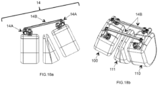
- connection can be made by means, for example, of a longitudinal fixing system 14 composed of hooks 14A and plates 14B ( Figures 18a and 18b ).
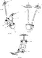
- a transverse rotation correction is carried out so as to bring the axes 16 of the correction instruments 10 into the same plane, as illustrated in the Figures 20a and 20b .
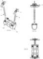
- a correction of the coronal displacement is then carried out by positioning the handles 17 of the correction instruments 10 parallel to each other, as illustrated in the figures 21 to 21c .
- the sagittal correction of the vertebrae is then carried out by bringing, as in the previous example of vertebrae straightening, the axes 16 of the correction instruments 10 parallel to each other ( Figure 17a ).
- the movements (transverse rotation, coronal displacement and sagittal displacement) applied to the vertebrae have been described sequentially. It is of course obvious that all of these movements can be performed in a single gesture.
- the measuring instrument 15 described in the initial phase of angular positioning of the correction instruments can also be used during all the surgical steps described in order to control and measure the progression of the correction.
- THE figures 22 and 23 represent an alternative embodiment of a vertebrae straightening assembly 1A.
- the implementation of the assembly remains similar to that previously described.
- the straightening assembly of this alternative differs from that previously described in terms of the arrangement of the connectors 500 as well as the anchoring means 200.
- the connector 500 is formed of two separate parts 500A, 500B,
- One of the parts 500A forms a sleeve intended to receive the triangulation bar 3.
- the sleeve is provided at each of its two ends with a notch 501A, 503A. It is provided on its external face with a threaded axis 502A.
- the notches are arranged opposite each other, on either side of the threaded axis.
- the other part 500B has a groove 501B arranged to receive the upper part 220 of the bone anchoring means. It has a hole 502B for the passage of the threaded shaft 502A.
- the groove 501B is arranged to be arranged opposite one of the notches 501A.
- the sleeve/threaded rod/upper portion arrangement of the bone anchor means is such that it allows multi-axial movement of the triangulation bar before full tightening of the nut, thereby allowing adjustment of the angular position of the correction instrument mounted on the triangulation bar (instrument not shown).
Landscapes
- Health & Medical Sciences (AREA)
- Orthopedic Medicine & Surgery (AREA)
- Neurology (AREA)
- Life Sciences & Earth Sciences (AREA)
- Surgery (AREA)
- Heart & Thoracic Surgery (AREA)
- Engineering & Computer Science (AREA)
- Biomedical Technology (AREA)
- Nuclear Medicine, Radiotherapy & Molecular Imaging (AREA)
- Medical Informatics (AREA)
- Molecular Biology (AREA)
- Animal Behavior & Ethology (AREA)
- General Health & Medical Sciences (AREA)
- Public Health (AREA)
- Veterinary Medicine (AREA)
- Surgical Instruments (AREA)
- Prostheses (AREA)
Claims (12)
- Anordnung zur Aufrichtung (1, 1A) von Wirbeln, umfassend:- zwei Knochenverankerungsmittel (2, 200), die dazu bestimmt sind, auf ein und demselben Wirbel implantiert zu sein,- eine Struktur zur Überbrückung der Knochenverankerungsmittel untereinander, wobei die implantierbare Überbrückungsstruktur eine Triangulationsstange (3) und Verbindungsmittel (4) umfasst, die es ermöglichen, die Triangulationsstange (3) mit jedem Knochenverankerungsmittel (2, 200) zu verbinden,- ein Korrekturinstrument (10), das an der Triangulationsstange angebracht ist,- Mittel zum Arretieren der Triangulationsstange (3) an den Knochenverankerungsmitteln mittels der Verbindungsmittel, wobei die Triangulationsstange somit mit den Knochenverankerungsmitteln eine starre dreieckige Anordnung bildet, und- Mittel zum Einstellen der Winkelposition des Korrekturinstruments (10) in Bezug auf den Wirbel gemäß einem bestimmten Winkel,wobei die Anordnung zur Aufrichtung (1, 1A) von Wirbeln dadurch gekennzeichnet ist, dass die Verbindungsmittel (4) zwei Verbinder (5) umfassen, die jeweils einen ersten Durchgangsbereich, der eine Längsdurchgangsachse für die Triangulationsstange (3) definiert, und einen zweiten Durchgangsbereich umfassen, der eingerichtet ist, um eines der Knochenverankerungsmittel zu empfangen, wobei der zweite Durchgangsbereich eine längliche Form aufweist, die parallel zur Längsdurchgangsachse des ersten Durchgangsbereichs ausgerichtet ist, wobei die Verbinder die Mittel zum Einstellen der Winkelposition des Korrekturinstruments (10) bilden.
- Anordnung zur Aufrichtung (1, 1A) von Wirbeln nach Anspruch 1, dadurch gekennzeichnet, dass die Verbindungsmittel die Mittel zum Einstellen der Winkelposition des Korrekturinstruments (10) umfassen.
- Anordnung zur Aufrichtung (1, 1A) von Wirbeln nach Anspruch 2, dadurch gekennzeichnet, dass die Triangulationsstange (3) einen Befestigungsbereich (33) für das Korrekturinstrument (10) aufweist, der eingerichtet ist, um eine rotations- und translationsfeste Befestigung des Korrekturinstruments (10) an der Triangulationsstange zu gewährleisten.
- Anordnung zur Aufrichtung (1, 1A) von Wirbeln nach Anspruch 3, dadurch gekennzeichnet, dass die Triangulationsstange (3) eine Abflachung aufweist, die den Befestigungsbereich (33) bildet.
- Anordnung zur Aufrichtung (1, 1A) von Wirbeln nach Anspruch 3 oder 4, dadurch gekennzeichnet, dass der Befestigungsbereich (33) zentral ist.
- Anordnung zur Aufrichtung (1) von Wirbeln nach einem der vorstehenden Ansprüche, dadurch gekennzeichnet, dass die erste Durchgangsbereich ausgebildet ist, um das Gleiten und die Rotation der Triangulationsstange (3) darin vor ihrem Arretieren an den Verbindern (5) zu gestatten.
- Anordnung zur Aufrichtung (1) von Wirbeln nach einem der vorstehenden Ansprüche, dadurch gekennzeichnet, dass jeder Verbinder (5) in Form einer Klammer vorliegt, die einen Teil mit einem C-förmigen Querschnitt umfasst, der durch zwei Arme verlängert wird, die jeweils eine Öffnung (523, 524) aufweisen, wobei die Öffnungen jedes Arms einander gegenüberliegend angeordnet sind, um den zweiten Durchgangsbereich zu definieren, während der C-förmige Querschnitt den ersten Durchgangsbereich begrenzt.
- Anordnung zur Aufrichtung (1) von Wirbeln nach Anspruch 7, dadurch gekennzeichnet, dass die Öffnungen (523, 524) so eingerichtet sind, dass sie einen axialen Versatz zueinander aufweisen.
- Anordnung zur Aufrichtung (1, 1A) von Wirbeln nach einem der vorstehenden Ansprüche, dadurch gekennzeichnet, dass jedes Knochenverankerungsmittel (2) einen festen Schraubenkopf (20) umfasst, der auf beiden Seiten durch einen unteren Gewindeabschnitt (21) zur Implantation in den Wirbel und einen oberen Gewindeabschnitt (22) verlängert ist, auf den eine die Arretierungsmittel bildende Spannmutter (6) bestimmt ist, geschraubt zu werden.
- Anordnung zur Aufrichtung (1, 1A) von Wirbeln nach einem der vorstehenden Ansprüche, dadurch gekennzeichnet, dass die Triangulationsstange (3) gerade oder gebogen ist.
- Wirbelsäulen-Osteosynthesesystem, das mindestens zwei Anordnungen zur Aufrichtung von Wirbeln nach einem der vorstehenden Ansprüche umfasst, wobei die Anordnungen (1, 1A) dazu bestimmt sind, auf zwei verschiedenen Wirbeln implantiert und miteinander verbunden zu sein.
- Wirbelsäulen-Osteosynthesesystem nach Anspruch 11, dadurch gekennzeichnet, dass es mindestens ein Bedienungsinstrument umfasst, das die Korrekturinstrumente (10) jeder der Triangulationsanordnungen miteinander verbindet.
Applications Claiming Priority (2)
| Application Number | Priority Date | Filing Date | Title |
|---|---|---|---|
| FR1853204A FR3080018B1 (fr) | 2018-04-12 | 2018-04-12 | Ensemble de triangulation permettant le redressement de vertebres, et systeme d’osteosynthese rachidienne comprenant de tels ensembles |
| PCT/FR2019/050866 WO2019197787A1 (fr) | 2018-04-12 | 2019-04-12 | Ensemble de triangulation permettant le redressement de vertèbres, et système d'osteosynthèse rachidienne comprenant de tels ensembles |
Publications (2)
| Publication Number | Publication Date |
|---|---|
| EP3773282A1 EP3773282A1 (de) | 2021-02-17 |
| EP3773282B1 true EP3773282B1 (de) | 2025-04-02 |
Family
ID=62874935
Family Applications (1)
| Application Number | Title | Priority Date | Filing Date |
|---|---|---|---|
| EP19723152.5A Active EP3773282B1 (de) | 2018-04-12 | 2019-04-12 | Triangulationsanordnung zum korrigieren der wirbelsäule und wirbelsäulenosteosynthesesystem mit solchen anordnungen |
Country Status (4)
| Country | Link |
|---|---|
| US (3) | US11864800B2 (de) |
| EP (1) | EP3773282B1 (de) |
| FR (1) | FR3080018B1 (de) |
| WO (1) | WO2019197787A1 (de) |
Families Citing this family (2)
| Publication number | Priority date | Publication date | Assignee | Title |
|---|---|---|---|---|
| US12544114B2 (en) * | 2020-05-04 | 2026-02-10 | Vb Spine Us Opco Llc | Segmental correction and spondylolisthesis reduction |
| WO2024186931A1 (en) * | 2023-03-06 | 2024-09-12 | Zimmer Biomet CMF and Thoracic, LLC | Pectus bar and stabilizer devices |
Citations (4)
| Publication number | Priority date | Publication date | Assignee | Title |
|---|---|---|---|---|
| US5196013A (en) * | 1989-11-03 | 1993-03-23 | Harms Juergen | Pedicel screw and correcting and supporting apparatus comprising such screw |
| FR2761876A1 (fr) * | 1997-04-09 | 1998-10-16 | Materiel Orthopedique En Abreg | Instrumentation d'osteosynthese lombaire pour la correction du spondylolisthesis par voie posterieure |
| WO2001054597A1 (fr) * | 2000-01-27 | 2001-08-02 | Scient'x | Dispositif de liaison intervertebrale avec une barre de connexion pour la fixation d'une tige de liaison |
| US20160015427A1 (en) * | 2011-02-08 | 2016-01-21 | Alphatec Spine, Inc. | Systems and Methods for Correcting Spinal Deformity |
Family Cites Families (6)
| Publication number | Priority date | Publication date | Assignee | Title |
|---|---|---|---|---|
| DE4200905A1 (de) * | 1992-01-16 | 1993-07-22 | Heinrich Ulrich | Implantat zur ausrichtung und fixierung zweier knochen oder knochenteile zueinander, insbesondere spondylodese-implantat |
| FR2789886B1 (fr) * | 1999-02-18 | 2001-07-06 | Dimso Sa | Dispositif de distraction/contraction pour systeme d'osteosynthese rachidienne |
| US7794464B2 (en) * | 2006-02-09 | 2010-09-14 | Warsaw Orthopedic, Inc. | Spinal derotation instruments and methods |
| WO2010094250A1 (de) * | 2009-02-19 | 2010-08-26 | Ulrich Gmbh & Co. Kg | Vorrichtung zur stabilisierung der wirbelsäule |
| US9198696B1 (en) * | 2010-05-27 | 2015-12-01 | Nuvasive, Inc. | Cross-connector and related methods |
| WO2012074803A1 (en) | 2010-11-29 | 2012-06-07 | Javier Pereiro De Lamo | Method and system for the treatment of spinal deformities |
-
2018
- 2018-04-12 FR FR1853204A patent/FR3080018B1/fr active Active
-
2019
- 2019-04-12 US US17/046,676 patent/US11864800B2/en active Active
- 2019-04-12 EP EP19723152.5A patent/EP3773282B1/de active Active
- 2019-04-12 WO PCT/FR2019/050866 patent/WO2019197787A1/fr not_active Ceased
-
2023
- 2023-11-28 US US18/521,409 patent/US12383313B2/en active Active
-
2025
- 2025-07-03 US US19/259,445 patent/US20260020882A1/en active Pending
Patent Citations (4)
| Publication number | Priority date | Publication date | Assignee | Title |
|---|---|---|---|---|
| US5196013A (en) * | 1989-11-03 | 1993-03-23 | Harms Juergen | Pedicel screw and correcting and supporting apparatus comprising such screw |
| FR2761876A1 (fr) * | 1997-04-09 | 1998-10-16 | Materiel Orthopedique En Abreg | Instrumentation d'osteosynthese lombaire pour la correction du spondylolisthesis par voie posterieure |
| WO2001054597A1 (fr) * | 2000-01-27 | 2001-08-02 | Scient'x | Dispositif de liaison intervertebrale avec une barre de connexion pour la fixation d'une tige de liaison |
| US20160015427A1 (en) * | 2011-02-08 | 2016-01-21 | Alphatec Spine, Inc. | Systems and Methods for Correcting Spinal Deformity |
Also Published As
| Publication number | Publication date |
|---|---|
| FR3080018A1 (fr) | 2019-10-18 |
| FR3080018B1 (fr) | 2024-04-19 |
| US12383313B2 (en) | 2025-08-12 |
| US20260020882A1 (en) | 2026-01-22 |
| US20210212732A1 (en) | 2021-07-15 |
| EP3773282A1 (de) | 2021-02-17 |
| US20240225702A9 (en) | 2024-07-11 |
| WO2019197787A1 (fr) | 2019-10-17 |
| US11864800B2 (en) | 2024-01-09 |
| US20240130763A1 (en) | 2024-04-25 |
Similar Documents
| Publication | Publication Date | Title |
|---|---|---|
| CA2133766C (fr) | Dispositif d'osteosynthese rachidienne | |
| EP2675375B1 (de) | Chirurgische vorrichtung zur korrektur von verformungen der wirbelsäule | |
| EP1303224B1 (de) | Halbsteifes verbindungsstück zur stabilisierung der wirbelsäule | |
| EP0947175B1 (de) | Vorrichtung zur Wirbelsäulenosteosynthese, welche an der Stellung eines Pedikelschraube anpassbar ist | |
| EP1415602B1 (de) | Modulare, platzsparende und multidirektionelle Osteosynthesevorrichtung für die Wirbelsäule | |
| EP0128058B1 (de) | Wirbelsäulenhaltevorrichtung | |
| EP1439790B9 (de) | Wirbelsäulenstützvorrichtung, die mit klemmen zusammengesetzt ist | |
| FR2781359A1 (fr) | Materiel d'osteosynthese rachidienne | |
| EP1898820B1 (de) | Instrument zur bewegung eines wirbels | |
| EP1075223A1 (de) | Wirbelsäulen-osteosynthesesystem insbesondere zur vorderen fixierung | |
| WO1994000062A1 (fr) | Appareil de traitement du rachis | |
| EP0846444A1 (de) | Vorrichtung zur Korrektur von Wirbelsäulenverkrummungen | |
| WO2006010844A1 (fr) | Dispositif d’autocorrection scoliotique ne necessitant plus d’interventions apres implantation | |
| US20260020882A1 (en) | Triangulation assembly for rectifying vertebrae, and spinal osteosynthesis system comprising such assemblies | |
| FR2790941A1 (fr) | Instrumentation d'osteosynthese rachidienne a plaque et vis pediculaire ou a connecteur transversal entre une tige vertebrale et une vis pediculaire | |
| WO2003032849A1 (fr) | Systeme pour maintenir au moins deux vertebres l'une par rapport a l'autre pour realiser une osteosynthese rachidienne | |
| FR2734471A1 (fr) | Dispositif d'osteosynthese rachidienne | |
| WO2016062963A1 (fr) | Dispositif d'ancrage vertebral multiaxial pour le redressement d'une vertebre | |
| EP3116426A1 (de) | Osteosynthesesystem mit mitteln zur begradigung eines knochenverankerungselements in bezug zu einem schraubenkopf und in solch ein system implementierte verankerungsschraube | |
| EP3082630B1 (de) | Wirbelfixiervorrichtung mit doppelter befestigung, system zur blockierung einer schleife mit solch einer vorrichtung | |
| EP2858584B1 (de) | Iliosakralimplantat zur verbindung mit einem spinalen osteosynthesesystem | |
| FR2714287A1 (fr) | Dispositif de stabilisation du rachis. | |
| FR2831419A1 (fr) | Appareil de maintien du rachis a assemblage a rotule | |
| WO2025045336A1 (fr) | Implant de fixation pelvienne trans-ilio-sacrée | |
| FR2924013A1 (fr) | Systeme de correction d'une deformation d'une colonne vertebrale |
Legal Events
| Date | Code | Title | Description |
|---|---|---|---|
| STAA | Information on the status of an ep patent application or granted ep patent |
Free format text: STATUS: UNKNOWN |
|
| STAA | Information on the status of an ep patent application or granted ep patent |
Free format text: STATUS: THE INTERNATIONAL PUBLICATION HAS BEEN MADE |
|
| PUAI | Public reference made under article 153(3) epc to a published international application that has entered the european phase |
Free format text: ORIGINAL CODE: 0009012 |
|
| STAA | Information on the status of an ep patent application or granted ep patent |
Free format text: STATUS: REQUEST FOR EXAMINATION WAS MADE |
|
| 17P | Request for examination filed |
Effective date: 20201110 |
|
| AK | Designated contracting states |
Kind code of ref document: A1 Designated state(s): AL AT BE BG CH CY CZ DE DK EE ES FI FR GB GR HR HU IE IS IT LI LT LU LV MC MK MT NL NO PL PT RO RS SE SI SK SM TR |
|
| AX | Request for extension of the european patent |
Extension state: BA ME |
|
| DAV | Request for validation of the european patent (deleted) | ||
| DAX | Request for extension of the european patent (deleted) | ||
| STAA | Information on the status of an ep patent application or granted ep patent |
Free format text: STATUS: EXAMINATION IS IN PROGRESS |
|
| P01 | Opt-out of the competence of the unified patent court (upc) registered |
Effective date: 20230427 |
|
| 17Q | First examination report despatched |
Effective date: 20230531 |
|
| RAP1 | Party data changed (applicant data changed or rights of an application transferred) |
Owner name: STRYKER EUROPEAN OPERATIONS LIMITED |
|
| RIN1 | Information on inventor provided before grant (corrected) |
Inventor name: PETIT, DOMINIQUE Inventor name: CHOPIN, DANIEL Inventor name: ASSAKER, RICHARD |
|
| GRAP | Despatch of communication of intention to grant a patent |
Free format text: ORIGINAL CODE: EPIDOSNIGR1 |
|
| STAA | Information on the status of an ep patent application or granted ep patent |
Free format text: STATUS: GRANT OF PATENT IS INTENDED |
|
| GRAJ | Information related to disapproval of communication of intention to grant by the applicant or resumption of examination proceedings by the epo deleted |
Free format text: ORIGINAL CODE: EPIDOSDIGR1 |
|
| INTG | Intention to grant announced |
Effective date: 20240814 |
|
| STAA | Information on the status of an ep patent application or granted ep patent |
Free format text: STATUS: EXAMINATION IS IN PROGRESS |
|
| GRAJ | Information related to disapproval of communication of intention to grant by the applicant or resumption of examination proceedings by the epo deleted |
Free format text: ORIGINAL CODE: EPIDOSDIGR1 |
|
| GRAP | Despatch of communication of intention to grant a patent |
Free format text: ORIGINAL CODE: EPIDOSNIGR1 |
|
| GRAP | Despatch of communication of intention to grant a patent |
Free format text: ORIGINAL CODE: EPIDOSNIGR1 |
|
| STAA | Information on the status of an ep patent application or granted ep patent |
Free format text: STATUS: GRANT OF PATENT IS INTENDED |
|
| GRAJ | Information related to disapproval of communication of intention to grant by the applicant or resumption of examination proceedings by the epo deleted |
Free format text: ORIGINAL CODE: EPIDOSDIGR1 |
|
| STAA | Information on the status of an ep patent application or granted ep patent |
Free format text: STATUS: EXAMINATION IS IN PROGRESS |
|
| INTC | Intention to grant announced (deleted) | ||
| GRAP | Despatch of communication of intention to grant a patent |
Free format text: ORIGINAL CODE: EPIDOSNIGR1 |
|
| STAA | Information on the status of an ep patent application or granted ep patent |
Free format text: STATUS: GRANT OF PATENT IS INTENDED |
|
| INTG | Intention to grant announced |
Effective date: 20241104 |
|
| GRAS | Grant fee paid |
Free format text: ORIGINAL CODE: EPIDOSNIGR3 |
|
| GRAA | (expected) grant |
Free format text: ORIGINAL CODE: 0009210 |
|
| STAA | Information on the status of an ep patent application or granted ep patent |
Free format text: STATUS: THE PATENT HAS BEEN GRANTED |
|
| AK | Designated contracting states |
Kind code of ref document: B1 Designated state(s): AL AT BE BG CH CY CZ DE DK EE ES FI FR GB GR HR HU IE IS IT LI LT LU LV MC MK MT NL NO PL PT RO RS SE SI SK SM TR |
|
| REG | Reference to a national code |
Ref country code: GB Ref legal event code: FG4D Free format text: NOT ENGLISH |
|
| REG | Reference to a national code |
Ref country code: CH Ref legal event code: EP |
|
| REG | Reference to a national code |
Ref country code: IE Ref legal event code: FG4D Free format text: LANGUAGE OF EP DOCUMENT: FRENCH |
|
| REG | Reference to a national code |
Ref country code: DE Ref legal event code: R096 Ref document number: 602019068057 Country of ref document: DE |
|
| REG | Reference to a national code |
Ref country code: DE Ref legal event code: R081 Ref document number: 602019068057 Country of ref document: DE Owner name: VB SPINE US OPCO LLC, WILMINGTON, US Free format text: FORMER OWNER: STRYKER EUROPEAN OPERATIONS LIMITED, CARRIGTWOHILL, COUNTY CORK, IE |
|
| REG | Reference to a national code |
Ref country code: GB Ref legal event code: 732E Free format text: REGISTERED BETWEEN 20250522 AND 20250528 |
|
| PGFP | Annual fee paid to national office [announced via postgrant information from national office to epo] |
Ref country code: DE Payment date: 20250325 Year of fee payment: 7 |
|
| REG | Reference to a national code |
Ref country code: NL Ref legal event code: MP Effective date: 20250402 |
|
| PG25 | Lapsed in a contracting state [announced via postgrant information from national office to epo] |
Ref country code: NL Free format text: LAPSE BECAUSE OF FAILURE TO SUBMIT A TRANSLATION OF THE DESCRIPTION OR TO PAY THE FEE WITHIN THE PRESCRIBED TIME-LIMIT Effective date: 20250402 |
|
| REG | Reference to a national code |
Ref country code: AT Ref legal event code: MK05 Ref document number: 1780523 Country of ref document: AT Kind code of ref document: T Effective date: 20250402 |
|
| PG25 | Lapsed in a contracting state [announced via postgrant information from national office to epo] |
Ref country code: PT Free format text: LAPSE BECAUSE OF FAILURE TO SUBMIT A TRANSLATION OF THE DESCRIPTION OR TO PAY THE FEE WITHIN THE PRESCRIBED TIME-LIMIT Effective date: 20250804 Ref country code: ES Free format text: LAPSE BECAUSE OF FAILURE TO SUBMIT A TRANSLATION OF THE DESCRIPTION OR TO PAY THE FEE WITHIN THE PRESCRIBED TIME-LIMIT Effective date: 20250402 Ref country code: FI Free format text: LAPSE BECAUSE OF FAILURE TO SUBMIT A TRANSLATION OF THE DESCRIPTION OR TO PAY THE FEE WITHIN THE PRESCRIBED TIME-LIMIT Effective date: 20250402 |
|
| REG | Reference to a national code |
Ref country code: LT Ref legal event code: MG9D |
|
| PG25 | Lapsed in a contracting state [announced via postgrant information from national office to epo] |
Ref country code: NO Free format text: LAPSE BECAUSE OF FAILURE TO SUBMIT A TRANSLATION OF THE DESCRIPTION OR TO PAY THE FEE WITHIN THE PRESCRIBED TIME-LIMIT Effective date: 20250702 Ref country code: GR Free format text: LAPSE BECAUSE OF FAILURE TO SUBMIT A TRANSLATION OF THE DESCRIPTION OR TO PAY THE FEE WITHIN THE PRESCRIBED TIME-LIMIT Effective date: 20250703 |
|
| PG25 | Lapsed in a contracting state [announced via postgrant information from national office to epo] |
Ref country code: PL Free format text: LAPSE BECAUSE OF FAILURE TO SUBMIT A TRANSLATION OF THE DESCRIPTION OR TO PAY THE FEE WITHIN THE PRESCRIBED TIME-LIMIT Effective date: 20250402 |
|
| PG25 | Lapsed in a contracting state [announced via postgrant information from national office to epo] |
Ref country code: BG Free format text: LAPSE BECAUSE OF FAILURE TO SUBMIT A TRANSLATION OF THE DESCRIPTION OR TO PAY THE FEE WITHIN THE PRESCRIBED TIME-LIMIT Effective date: 20250402 |
|
| PG25 | Lapsed in a contracting state [announced via postgrant information from national office to epo] |
Ref country code: HR Free format text: LAPSE BECAUSE OF FAILURE TO SUBMIT A TRANSLATION OF THE DESCRIPTION OR TO PAY THE FEE WITHIN THE PRESCRIBED TIME-LIMIT Effective date: 20250402 |
|
| PG25 | Lapsed in a contracting state [announced via postgrant information from national office to epo] |
Ref country code: AT Free format text: LAPSE BECAUSE OF FAILURE TO SUBMIT A TRANSLATION OF THE DESCRIPTION OR TO PAY THE FEE WITHIN THE PRESCRIBED TIME-LIMIT Effective date: 20250402 |
|
| PG25 | Lapsed in a contracting state [announced via postgrant information from national office to epo] |
Ref country code: RS Free format text: LAPSE BECAUSE OF FAILURE TO SUBMIT A TRANSLATION OF THE DESCRIPTION OR TO PAY THE FEE WITHIN THE PRESCRIBED TIME-LIMIT Effective date: 20250702 |
|
| PG25 | Lapsed in a contracting state [announced via postgrant information from national office to epo] |
Ref country code: IS Free format text: LAPSE BECAUSE OF FAILURE TO SUBMIT A TRANSLATION OF THE DESCRIPTION OR TO PAY THE FEE WITHIN THE PRESCRIBED TIME-LIMIT Effective date: 20250802 |
|
| PG25 | Lapsed in a contracting state [announced via postgrant information from national office to epo] |
Ref country code: LV Free format text: LAPSE BECAUSE OF FAILURE TO SUBMIT A TRANSLATION OF THE DESCRIPTION OR TO PAY THE FEE WITHIN THE PRESCRIBED TIME-LIMIT Effective date: 20250402 |
|
| REG | Reference to a national code |
Ref country code: CH Ref legal event code: H13 Free format text: ST27 STATUS EVENT CODE: U-0-0-H10-H13 (AS PROVIDED BY THE NATIONAL OFFICE) Effective date: 20251125 |
|
| PG25 | Lapsed in a contracting state [announced via postgrant information from national office to epo] |
Ref country code: LU Free format text: LAPSE BECAUSE OF NON-PAYMENT OF DUE FEES Effective date: 20250412 |
|
| REG | Reference to a national code |
Ref country code: BE Ref legal event code: MM Effective date: 20250430 |
|
| REG | Reference to a national code |
Ref country code: DE Ref legal event code: R097 Ref document number: 602019068057 Country of ref document: DE |
|
| PG25 | Lapsed in a contracting state [announced via postgrant information from national office to epo] |
Ref country code: DK Free format text: LAPSE BECAUSE OF FAILURE TO SUBMIT A TRANSLATION OF THE DESCRIPTION OR TO PAY THE FEE WITHIN THE PRESCRIBED TIME-LIMIT Effective date: 20250402 Ref country code: SM Free format text: LAPSE BECAUSE OF FAILURE TO SUBMIT A TRANSLATION OF THE DESCRIPTION OR TO PAY THE FEE WITHIN THE PRESCRIBED TIME-LIMIT Effective date: 20250402 |
|
| PG25 | Lapsed in a contracting state [announced via postgrant information from national office to epo] |
Ref country code: BE Free format text: LAPSE BECAUSE OF NON-PAYMENT OF DUE FEES Effective date: 20250430 |
|
| PG25 | Lapsed in a contracting state [announced via postgrant information from national office to epo] |
Ref country code: CH Free format text: LAPSE BECAUSE OF NON-PAYMENT OF DUE FEES Effective date: 20250430 |
|
| PG25 | Lapsed in a contracting state [announced via postgrant information from national office to epo] |
Ref country code: CZ Free format text: LAPSE BECAUSE OF FAILURE TO SUBMIT A TRANSLATION OF THE DESCRIPTION OR TO PAY THE FEE WITHIN THE PRESCRIBED TIME-LIMIT Effective date: 20250402 |
|
| PG25 | Lapsed in a contracting state [announced via postgrant information from national office to epo] |
Ref country code: EE Free format text: LAPSE BECAUSE OF FAILURE TO SUBMIT A TRANSLATION OF THE DESCRIPTION OR TO PAY THE FEE WITHIN THE PRESCRIBED TIME-LIMIT Effective date: 20250402 |
|
| PG25 | Lapsed in a contracting state [announced via postgrant information from national office to epo] |
Ref country code: RO Free format text: LAPSE BECAUSE OF FAILURE TO SUBMIT A TRANSLATION OF THE DESCRIPTION OR TO PAY THE FEE WITHIN THE PRESCRIBED TIME-LIMIT Effective date: 20250402 Ref country code: SK Free format text: LAPSE BECAUSE OF FAILURE TO SUBMIT A TRANSLATION OF THE DESCRIPTION OR TO PAY THE FEE WITHIN THE PRESCRIBED TIME-LIMIT Effective date: 20250402 |
|
| PG25 | Lapsed in a contracting state [announced via postgrant information from national office to epo] |
Ref country code: IT Free format text: LAPSE BECAUSE OF FAILURE TO SUBMIT A TRANSLATION OF THE DESCRIPTION OR TO PAY THE FEE WITHIN THE PRESCRIBED TIME-LIMIT Effective date: 20250402 |
|
| PG25 | Lapsed in a contracting state [announced via postgrant information from national office to epo] |
Ref country code: MC Free format text: LAPSE BECAUSE OF FAILURE TO SUBMIT A TRANSLATION OF THE DESCRIPTION OR TO PAY THE FEE WITHIN THE PRESCRIBED TIME-LIMIT Effective date: 20250402 |
|
| PLBE | No opposition filed within time limit |
Free format text: ORIGINAL CODE: 0009261 |
|
| STAA | Information on the status of an ep patent application or granted ep patent |
Free format text: STATUS: NO OPPOSITION FILED WITHIN TIME LIMIT |
|
| REG | Reference to a national code |
Ref country code: CH Ref legal event code: L10 Free format text: ST27 STATUS EVENT CODE: U-0-0-L10-L00 (AS PROVIDED BY THE NATIONAL OFFICE) Effective date: 20260211 |
|
| 26N | No opposition filed |
Effective date: 20260105 |
|
| PGFP | Annual fee paid to national office [announced via postgrant information from national office to epo] |
Ref country code: GB Payment date: 20260223 Year of fee payment: 8 |
|
| PG25 | Lapsed in a contracting state [announced via postgrant information from national office to epo] |
Ref country code: IE Free format text: LAPSE BECAUSE OF NON-PAYMENT OF DUE FEES Effective date: 20250412 |
|
| PGFP | Annual fee paid to national office [announced via postgrant information from national office to epo] |
Ref country code: FR Payment date: 20260223 Year of fee payment: 8 |