EP3772665A1 - Methods and devices using effective elastic parameter values for anisotropic media - Google Patents
Methods and devices using effective elastic parameter values for anisotropic media Download PDFInfo
- Publication number
- EP3772665A1 EP3772665A1 EP20305752.6A EP20305752A EP3772665A1 EP 3772665 A1 EP3772665 A1 EP 3772665A1 EP 20305752 A EP20305752 A EP 20305752A EP 3772665 A1 EP3772665 A1 EP 3772665A1
- Authority
- EP
- European Patent Office
- Prior art keywords
- isotropic
- seismic
- elastic parameter
- parameter values
- eff
- Prior art date
- Legal status (The legal status is an assumption and is not a legal conclusion. Google has not performed a legal analysis and makes no representation as to the accuracy of the status listed.)
- Pending
Links
- 238000000034 method Methods 0.000 title claims abstract description 107
- 230000015572 biosynthetic process Effects 0.000 claims abstract description 41
- 238000012545 processing Methods 0.000 claims abstract description 36
- 238000004458 analytical method Methods 0.000 claims description 23
- 239000004215 Carbon black (E152) Substances 0.000 claims description 11
- 229930195733 hydrocarbon Natural products 0.000 claims description 11
- 150000002430 hydrocarbons Chemical class 0.000 claims description 11
- 238000001615 p wave Methods 0.000 claims description 9
- 238000005755 formation reaction Methods 0.000 description 29
- 230000004044 response Effects 0.000 description 8
- 230000014509 gene expression Effects 0.000 description 7
- 238000002310 reflectometry Methods 0.000 description 7
- 230000000694 effects Effects 0.000 description 6
- 230000001419 dependent effect Effects 0.000 description 3
- 238000013500 data storage Methods 0.000 description 2
- 238000010586 diagram Methods 0.000 description 2
- 238000002474 experimental method Methods 0.000 description 2
- 230000008569 process Effects 0.000 description 2
- 229920000535 Tan II Polymers 0.000 description 1
- 238000013459 approach Methods 0.000 description 1
- 238000005452 bending Methods 0.000 description 1
- 230000005540 biological transmission Effects 0.000 description 1
- 230000008859 change Effects 0.000 description 1
- 238000004891 communication Methods 0.000 description 1
- 238000007796 conventional method Methods 0.000 description 1
- 230000010485 coping Effects 0.000 description 1
- 238000007405 data analysis Methods 0.000 description 1
- 238000009826 distribution Methods 0.000 description 1
- 239000012530 fluid Substances 0.000 description 1
- 238000010348 incorporation Methods 0.000 description 1
- 238000011835 investigation Methods 0.000 description 1
- 239000011159 matrix material Substances 0.000 description 1
- 238000005259 measurement Methods 0.000 description 1
- 238000012986 modification Methods 0.000 description 1
- 230000004048 modification Effects 0.000 description 1
- 230000010287 polarization Effects 0.000 description 1
- 238000007781 pre-processing Methods 0.000 description 1
- 230000008707 rearrangement Effects 0.000 description 1
- 239000013049 sediment Substances 0.000 description 1
- 238000000926 separation method Methods 0.000 description 1
- 238000013517 stratification Methods 0.000 description 1
- 238000006467 substitution reaction Methods 0.000 description 1
- 230000001131 transforming effect Effects 0.000 description 1
Images


Classifications
-
- G—PHYSICS
- G01—MEASURING; TESTING
- G01V—GEOPHYSICS; GRAVITATIONAL MEASUREMENTS; DETECTING MASSES OR OBJECTS; TAGS
- G01V1/00—Seismology; Seismic or acoustic prospecting or detecting
- G01V1/28—Processing seismic data, e.g. for interpretation or for event detection
-
- G—PHYSICS
- G01—MEASURING; TESTING
- G01V—GEOPHYSICS; GRAVITATIONAL MEASUREMENTS; DETECTING MASSES OR OBJECTS; TAGS
- G01V1/00—Seismology; Seismic or acoustic prospecting or detecting
- G01V1/28—Processing seismic data, e.g. for interpretation or for event detection
- G01V1/30—Analysis
- G01V1/307—Analysis for determining seismic attributes, e.g. amplitude, instantaneous phase or frequency, reflection strength or polarity
-
- G—PHYSICS
- G01—MEASURING; TESTING
- G01V—GEOPHYSICS; GRAVITATIONAL MEASUREMENTS; DETECTING MASSES OR OBJECTS; TAGS
- G01V1/00—Seismology; Seismic or acoustic prospecting or detecting
- G01V1/28—Processing seismic data, e.g. for interpretation or for event detection
- G01V1/282—Application of seismic models, synthetic seismograms
-
- G—PHYSICS
- G01—MEASURING; TESTING
- G01V—GEOPHYSICS; GRAVITATIONAL MEASUREMENTS; DETECTING MASSES OR OBJECTS; TAGS
- G01V1/00—Seismology; Seismic or acoustic prospecting or detecting
- G01V1/28—Processing seismic data, e.g. for interpretation or for event detection
- G01V1/30—Analysis
-
- G—PHYSICS
- G01—MEASURING; TESTING
- G01V—GEOPHYSICS; GRAVITATIONAL MEASUREMENTS; DETECTING MASSES OR OBJECTS; TAGS
- G01V2210/00—Details of seismic processing or analysis
- G01V2210/50—Corrections or adjustments related to wave propagation
- G01V2210/58—Media-related
- G01V2210/586—Anisotropic media
-
- G—PHYSICS
- G01—MEASURING; TESTING
- G01V—GEOPHYSICS; GRAVITATIONAL MEASUREMENTS; DETECTING MASSES OR OBJECTS; TAGS
- G01V2210/00—Details of seismic processing or analysis
- G01V2210/60—Analysis
- G01V2210/62—Physical property of subsurface
- G01V2210/624—Reservoir parameters
- G01V2210/6242—Elastic parameters, e.g. Young, Lamé or Poisson
-
- G—PHYSICS
- G01—MEASURING; TESTING
- G01V—GEOPHYSICS; GRAVITATIONAL MEASUREMENTS; DETECTING MASSES OR OBJECTS; TAGS
- G01V2210/00—Details of seismic processing or analysis
- G01V2210/60—Analysis
- G01V2210/63—Seismic attributes, e.g. amplitude, polarity, instant phase
-
- G—PHYSICS
- G01—MEASURING; TESTING
- G01V—GEOPHYSICS; GRAVITATIONAL MEASUREMENTS; DETECTING MASSES OR OBJECTS; TAGS
- G01V2210/00—Details of seismic processing or analysis
- G01V2210/60—Analysis
- G01V2210/64—Geostructures, e.g. in 3D data cubes
-
- G—PHYSICS
- G01—MEASURING; TESTING
- G01V—GEOPHYSICS; GRAVITATIONAL MEASUREMENTS; DETECTING MASSES OR OBJECTS; TAGS
- G01V2210/00—Details of seismic processing or analysis
- G01V2210/60—Analysis
- G01V2210/66—Subsurface modeling
Definitions
- Embodiments of the subject matter disclosed herein generally relate to methods and devices for seismic data modeling and inversion for anisotropic media and, more particularly, to using isotropic-type processing with effective elastic parameter values based on anisotropy and elastic parameter values.
- Seismic data is routinely acquired to obtain information about subsurface structure, stratigraphy, lithology and fluids contained in underground formations (sometimes called simply "earth”). Seismic data is a term used for recordings of an underground structure's response to seismic waves (also called “acoustic waves”). The seismic waves are reflected in underground formations at locations of changes in earth properties that impact the seismic wave propagation.
- Modeling is used to gain understanding of seismic wave propagation and to help analyze seismic data.
- seismic responses are estimated using models of earth properties and seismic wave propagation modeling algorithms.
- Models of earth properties are often specified in terms of physical parameters.
- modeling methods are widely used to study changes in seismic reflection amplitudes with the changing angle of incidence of a plane wave reflecting from a flat interface as described in the article by Castagna, J. P., and Backus, M. M., "Offset-dependent reflectivity - Theory and practice of AVO analysis,” published in Investigations in Geophysics Series No. 8, 1993 , Society of Exploration Geophysicists (incorporated herewith by reference in its entirety).
- a source seismic wavelet may be used to model the earth response.
- earth parameters are estimated based on the measured seismic responses, and an estimate of the source seismic wavelet.
- Inversion methods are generally based on forward models of seismic wave propagation, and some make use of some input elastic parameter data such as low frequency trend information or statistical distributions. Other inversion methods use some calibration of seismic amplitudes, performed in a pre-processing step or as part of an algorithm.
- estimates of earth properties obtained from the inversion methods are generally provided as a series of 2D sections or 3D volumes of elastic parameter values. Inversion is often followed by analysis and interpretation of the inversion results. Available borehole log measurements may be used during the analysis and interpretation.
- Local isotropy is a core assumption of most conventional methods for forward modeling, wavelet estimation, inversion, analysis and interpretation of inversion results, as well as analysis and interpretation of seismic data.
- Local isotropy assumption considers the earth (i.e., the underground formation) to be a stack of layers, with each layer being described by a physical parameter or property with the same value when measured in different directions. Such methods are referred to hereinafter as "isotropic" methods.
- anisotropic seismic data Seismic data affected by the anisotropy.
- Earth parameters that describe anisotropy are referred to as anisotropy parameters.
- Anisotropy has to be taken into consideration in order to improve the accuracy of seismic modeling, wavelet estimation, inversion, and the analysis and interpretation of inversion results for anisotropic seismic data.
- anisotropy makes seismic processing mathematically and numerically more complex than similar isotropic methods. Modeling methods (such as wavelet estimation and certain types of seismic data analysis and interpretation) must also be expanded to incorporate the anisotropy parameters, which makes them more challenging to use. Moreover, from the inversion perspective, explicit incorporation of anisotropy parameters is difficult. Performing inversion for the elastic parameters from amplitude-variation with offset (AVO) seismic data is recognized to be a difficult problem for most seismic data acquisition geometries. If the anisotropy parameters are also included in inversion, the number of unknown values increases, making it even harder to find a solution. Adding more parameters and coping with such difficulties also complicates the analysis and interpretation of inversion results.
- AVO amplitude-variation with offset
- anisotropic elastic parameters here called effective elastic parameters for anisotropic medium
- anisotropic media vertically transverse isotropic (VTI) media, which possess polar anisotropy characteristics
- HAI horizontally transverse isotropic
- underground formations may not be characterized by HTI or VTI anisotropy, being instead tilted transverse isotropic (TTI) and/or orthorhombic anisotropy (which are more general anisotropy types than VTI and HTI).
- TTI tilted transverse isotropic
- orthorhombic anisotropy which are more general anisotropy types than VTI and HTI.
- Various embodiments for modeling and seismic data inversion related to underground formation including anisotropic media use effective elastic parameter values based on anisotropy and elastic parameter values. Take into consideration anisotropy effects in this manner allows an efficient and accurate processing for orthorhombic and tilted transverse isotropic (TTI) media. Not taking into consideration the anisotropy effects may cause a significant error in locating hydrocarbon reservoirs.
- TTI transverse isotropic
- a method for seismic exploration of an underground formation including an orthorhombic anisotropic medium includes obtaining seismic data acquired for the underground formation, wherein the seismic data includes seismic amplitudes detected at plural values of an azimuth angle, ⁇ - ⁇ , of a source-receiver direction relative to a principal axis of the orthorhombic anisotropic medium.
- the method further includes calculating elastic parameter values and anisotropy parameter values related to the orthorhombic anisotropic medium based on the seismic data, and performing an isotropic-type processing technique using effective elastic parameter values calculated based on the elastic parameter values, the anisotropy parameter values, and the azimuth angle for the orthorhombic anisotropic medium.
- the isotropic-type processing technique leads to a quantitative model of the underground formation usable to locate hydrocarbon reservoirs.
- a method for seismic exploration of an underground formation including a tilted transverse isotropic, TTI, medium having a symmetry axis tilted at a tilt angle ⁇ relative to a horizontal plane thereof.
- the method includes obtaining seismic data acquired for the underground formation, wherein the seismic data includes seismic amplitudes detected at plural values of an azimuth angle, ⁇ - ⁇ , of a source-receiver direction relative to a projection of the symmetry axis in a horizontal plane.
- the method further includes calculating elastic parameter values and anisotropy parameter values related to the TTI medium based on the seismic data, and performing an isotropic-type processing technique using effective elastic parameter values calculated based on the elastic parameter values, the anisotropy parameter values, the values of the azimuth angle and of the tilt angle for the TTI medium.
- the isotropic-type processing technique leads to a quantitative model of the underground formation usable to locate hydrocarbon reservoirs.
- a seismic data processing apparatus for exploration of an underground formation.
- the apparatus includes an interface configured to obtain seismic data acquired for the underground formation, wherein the seismic data includes seismic amplitudes detected at plural values of an azimuth angle, ⁇ - ⁇ , of a source-receiver direction relative to (1) a principal axis of the orthorhombic anisotropic medium if the underground formation includes an orthorhombic anisotropic medium, or (2) relative to a projection of a symmetry axis in a horizontal plane, if the underground formation includes a tilted transverse isotropic, TTI, medium having a symmetry axis tilted at a tilt angle ⁇ relative to an isotropy plane thereof.
- TTI transverse isotropic
- the apparatus also includes a central processing unit connected to the interface and configured (A) to calculate elastic parameter values and anisotropy parameter values related to the orthorhombic anisotropic medium or to the TTI medium based on the seismic data, and (B) to perform an isotropic-type processing technique using effective elastic parameter values calculated based on the elastic parameter values, and the anisotropy parameter values and the azimuth angle.
- the isotropic-type processing technique leads to a quantitative model of the underground formation usable to locate hydrocarbon reservoirs, and the effective elastic parameter values depend also on the tilt angles for TTI medium.
- Methods and devices that process seismic data taking into account the effects of anisotropy associated with tilted transverse isotropic (TTI) and orthorhombic media (i.e., subsurface layers being imaged which possess azimuthal anisotropy) are describes in this section.
- earth elastic and anisotropy parameters associated with TTI and orthorhombic media are converted into anisotropic parameters used in isotropic seismic data processing such as, but not limited to, seismic modeling, wavelet estimation, inversion, the analysis and interpretation of inversion results, and the analysis and interpretation of seismic data.
- FIG. 1 Prior to discussing such embodiments in detail, consider system 100 for land seismic data acquisition illustrated in Figure 1 .
- This system is configured to generate, transmit and receive seismic waves thereby exploring underground formations.
- Such exploration may determine the absence or presence of hydrocarbon deposits (such as 10 in sediment layer 12) or at least the probability of the absence or presence of hydrocarbon deposits underground.
- System 100 includes a seismic wave source 110, which may be a vibrator moved to different locations by the first vehicle/truck 112.
- the seismic source generates seismic waves.
- Some of the seismic waves' energy is detected by receivers 130 (e.g., geophones).
- the receivers convert the detected waves into electrical signals recorded by seismic data acquisition system 120 (which can be located, for example, on vehicle/truck 122).
- Source 110, receivers 130, and data acquisition system 120 are placed on ground surface 11 and are interconnected by one or more cables 132.
- Vehicle 122 may communicate wirelessly with vehicle 112 via antenna 124 and 114, respectively.
- Antenna 134 may facilitate wireless communications of the receivers with vehicles 112 and 122.
- Seismic waves generated by source 110 propagate on the ground surface 11 as surface wave 111 and underground as transmitted waves 116.
- the transmitted waves are partially reflected at interface 13 between layers 12 and 14 (which have different wave propagation properties) as reflected waves 118.
- the surface and the reflected waves may be detected by receivers 130 that convert the detected seismic energy into an electrical signal.
- the electrical signal represents both reflected waves and surface waves, which are undesirable and filtered out as much as is practically possible during seismic data processing.
- Data acquisition system 120 samples the electrical signals, yielding a series of sample amplitude versus time, which is the seismic data.
- Figure 1 illustrates a linear land data acquisition.
- receivers may be placed on a survey area enabling data acquisition for different azimuth angles (i.e., different angles of source-receiver direction relative to a reference direction) as illustrated, for example, in U.S. Patent No. 9,791,578 .
- seismic data acquired with streamer spreads towed yields at least a narrow range of azimuth angles.
- This limited range may be extended by using an assembly of vessels as described, for example, in U.S. Patent 9,482,773 , of by placing a seismic source in a middle of a streamer spread.
- Figure 2 illustrates an HTI medium with vertical fractures that are substantially parallel with an isotropy plane and substantially perpendicular to symmetry axes in a symmetry plane.
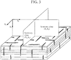
- Figure 3 illustrates an orthorhombic medium with two orthogonal systems of parallel fractures, thus having two vertical symmetry planes.
- Figures 2 and 3 are adapted from 1997 article "Anisotropic parameters and P-wave velocity for orthorhombic media" by Tsvankin, I. published in Geophysics, vol. 62, no. 4, pp. 1292-1309 .
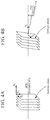
- Figure 4A illustrates HTI and Figure 4B illustrates TTI. Different from HTI, in TTI the symmetry axis is tilted with respect to a horizontal plane by a given angle ⁇ .
- FIG. 5 illustrates another example of an anisotropic medium.
- the illustrated orthorhombic medium's anisotropy is caused by two orthogonal systems of vertical parallel cracks and also by a horizontal fine layering.
- three symmetry planes are orthogonal to one another, with one symmetry plane being horizontal and the other two being vertical.
- Both TTI and orthorhombic media also known as media with azimuthal anisotropy
- AVO Amplitude Versus Offset AVO
- AVO may be converted, for example, to angles for Amplitude Versus Angle (AVA) analysis and interpretation.
- AVO may be converted, for example, to angles for Amplitude Versus Angle (AVA) analysis and interpretation.
- AVO may be converted, for example, to angles for Amplitude Versus Angle (AVA) analysis and interpretation.
- AVO may be converted, for example, to angles for Amplitude Versus Angle (AVA) analysis and interpretation.
- the link between the subsurface parameters and AVO is determined by seismic wave propagation modeling. For the most general case, this leads to a very complex relationship that can only be solved by numerical wave equation modeling.
- Most conventional modeling methods are based on a simplified wave propagation model. For example, the following assumption has been used to define a simplified seismic wave propagation model: the earth (i.e., underground formation) is stratified into isotropic parallel layers; seismic waves propagate as plane waves impinging on each interface at a constant angle; each interface acts as an independent reflector; transmission effects other than ray bending are neglected; and the calculated plane wave reflection coefficients assume that half-spaces above and below the reflector interface are isotropic.
- the following embodiments use effective elastic parameters for anisotropic medium.
- the effective elastic parameters which are based on the anisotropy parameters and the elastic parameters, are used in the isotropic-type techniques applied to the seismic data. These effective elastic parameters take into consideration azimuthal anisotropy to an acceptable level of accuracy.
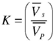
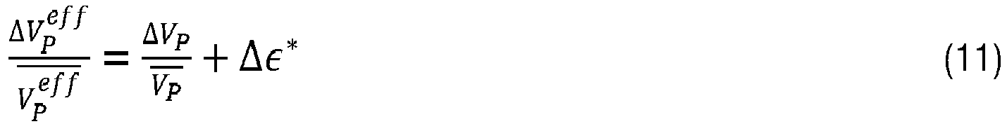
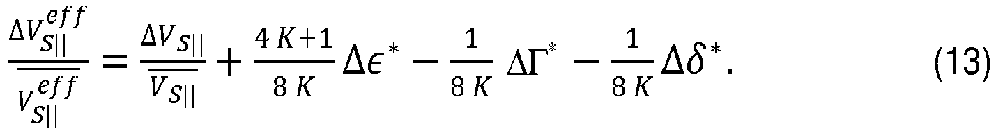
- V P eff , V S eff ,and ⁇ eff are defined such that the PP reflectivity coefficients have an identical form to the isotropic media case of Aki-Richards (see Aki, K.T., and Richards, P.G., "Quantitative Seismology: Theory and Methods," Vol. 1, published in 1980 by W.H.
- ⁇ is the azimuth of the x 1 principal axis (relative to an arbitrary reference)
- ⁇ is the azimuth of the source - receiver direction (relative to the same reference)
- the reflectivity expressions for TTI media are derived from the general anisotropic expression for PP wave reflectivity.
- V P is the P -velocity as referenced within the isotropy symmetry plane
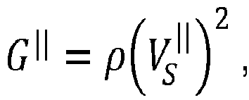
- G ⁇ is the shear modulus
- G ⁇ ⁇ V S ⁇ 2
- V S ⁇ is the reference shear velocity that corresponds to the fast shear wave as defined within the isotropy symmetry plane
- ⁇ r * ⁇ ⁇ V sin ⁇ 2 + ⁇ V ⁇ ⁇ V sin ⁇ 4
- g r * ⁇ 2 ⁇ V sin ⁇ 2
- ⁇ is the tilt angle between the symmetry axis and the horizontal plane (see Figure 4 ).
- the functions ⁇ * ( ⁇ , ⁇ , ⁇ ), ⁇ * ( ⁇ , ⁇ , ⁇ ) and ⁇ * ( ⁇ , ⁇ , ⁇ ) are similar to the ones in formula (8), (9) and (10) but also depend on the tilt angle ⁇ .
- the ⁇ is the azimuth angle of the projection of the symmetry axis in a horizontal plane.
- Formulas for the reflectivity coefficient were written by choosing the reference velocities within the isotropy plane. In turn, these formulas could be equivalently rewritten by choosing the reference P - and S - velocities along the anisotropic symmetry axis, by defining the so-called VTI reference system.
- G ⁇ ⁇ V ⁇ S 2 is the shear modulus
- ⁇ ⁇ r * ⁇ ⁇ ⁇ sin ⁇ ⁇ 2 + ⁇ ⁇ ⁇ sin ⁇ ⁇ 4
- g ⁇ r * ⁇ ⁇ 2 ⁇ sin ⁇ ⁇ 2 .
- the tilt angle ⁇ is the angle between the symmetry axis and the vertical direction.
- E eff ⁇ r X ⁇ r Y ⁇ r Z E with ⁇ r X , ⁇ r Y , ⁇ r Z defined by equations (26), (27) and (28).
- Exponents X, Y, Z, U, V, W from equations (71) and (72) are independent from the elastic parameters and Thomsen parameters, but they may depend on K. It should be noted that these exponents are different for each of the elastic parameters and for each type of anisotropy.
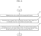
- Figure 6 is a flowchart illustrating a method 600 for seismic exploration of an underground formation including an orthorhombic anisotropic medium according to an embodiment.
- method 600 includes obtaining seismic data acquired for the underground formation, wherein the seismic data includes seismic amplitudes detected at plural values of an azimuth angle, ⁇ - ⁇ , of a source-receiver direction relative to a principal axis of the orthorhombic anisotropic medium.
- Method 600 further includes calculating elastic parameter values and anisotropy parameter values related to the orthorhombic anisotropic medium based on the seismic data at 620.
- the calculated values may include values for V P , V S ⁇ , ⁇ , ⁇ (1) , ⁇ (2) , ⁇ (1) , ⁇ (2) , ⁇ (3) , ⁇ (3) , ⁇ , ⁇ . These values may be obtained via conventional seismic data processing, where offset and azimuth-dependent time shifts are indicative of changes in the propagation velocity. Additionally, at the position of the well borehole, one can perform additional seismic experiments to specifically recover TTI and/or orthorhombic parameters. Such experiments are known as walk-away and walk-around VSP (Vertical Seismic Profiling).
- Method 600 further includes performing an isotropic-type processing technique using effective elastic parameter values at 630.
- the effective elastic parameter values are calculated based on the elastic parameter values, the anisotropy parameter values, and the azimuth angle (as in equations (14), (15) and (16)).
- the isotropic-type processing technique leads to a quantitative model of the underground formation usable to locate hydrocarbon reservoirs. That is, the output of the isotropic-type processing technique is a quantitative model of the orthorhombic anisotropic medium within the orthorhombic anisotropic medium.
- the isotropic-type processing technique may be an isotropic seismic modeling method, an isotropic seismic analysis and interpretation method, an isotropic seismic wavelet estimation method, an isotropic seismic inversion method, or an isotropic method for analysis and interpretation of inversion results to produce processed effective elastic parameter data.
- An elastic parameter E may have a corresponding effective elastic parameter E eff expressed as in equation (71).
- a elastic parameter E may have a corresponding effective elastic parameter E eff expressed as in equation (73).
- the elastic parameters values may represent p-wave velocity, s-wave velocity and density.
- the elastic parameters values may represent p-wave impedance, s-wave impedance and density.
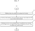
- Figure 7 is a flowchart illustrating a method 700 for seismic exploration of an underground formation including a TTI medium having a symmetry axis tilted at a tilt angle ⁇ relative to a horizontal plane thereof according to an embodiment.
- Method 700 includes obtaining seismic data acquired for the underground formation at 710.
- the seismic data includes seismic amplitudes detected at plural values of an azimuth angle, ⁇ - ⁇ , of a source-receiver direction relative to a projection of the symmetry axis in the horizontal plane.
- Method 700 further includes calculating elastic parameter values and anisotropy parameter values related to the TTI medium based on the seismic data at 720.
- Step 720 is similar to step 620 of method 600.
- the calculated values may include values for V P , V S ⁇ , ⁇ , ⁇ ( V ) , ⁇ ( V ) , ⁇ , ⁇ , ⁇ .
- Method 700 further includes performing an isotropic-type processing technique using effective elastic parameter values at 730.
- the effective elastic parameter values are calculated based on the elastic parameter values, the anisotropy parameter values, the values of the azimuth angle and of the tilt angle (equations (51), (52), (53)).
- the isotropic-type processing technique leads to quantitative model of the underground formation usable to locate hydrocarbon reservoirs.
- the isotropic-type processing technique in methods 600 and 700 may be an isotropic seismic modeling method to synthesize anisotropic seismic data. Additionally, the synthesized anisotropic seismic data may be used in an isotropic seismic analysis and interpretation method for analysis and interpretation of anisotropic seismic data. Accordingly, the azimuthal effective elastic parameter data may be substituted for the isotropic elastic parameters in any of the above-mentioned methods.
- Another embodiment is directed to a method for approximating anisotropic seismic modeling by applying isotropic seismic modeling.
- the method includes an initial step of inputting earth elastic parameter data and earth anisotropy parameter data for an area of interest. Next, the earth elastic parameter data is transformed to obtain effective elastic parameter data based on the earth anisotropy parameter data. Isotropic seismic modeling is then applied to the transformed effective elastic parameter data. The resulting modeled anisotropic seismic data is an approximation of seismic data obtained by a corresponding anisotropic seismic modeling. The processed anisotropic seismic data is then output.
- the method may further include a step of substituting the effective elastic parameter data for isotropic elastic parameter data to synthesize the anisotropic seismic data.
- the synthesized anisotropic seismic data may be used in an isotropic analysis and interpretation method for analysis and interpretation of the anisotropic seismic data.
- the area of interest may be imaged by acquisition of borehole data, wide azimuth (WAZ) data, three-dimension (3D) earth models, or four-dimensional (4D) earth models.
- WAZ wide azimuth
- 3D three-dimension
- 4D four-dimensional
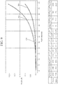
- Figures 8 and 9 illustrate modeling results for layers with relatively strong anisotropy contrasts.
- Figure 8 illustrates the effect of using the 3-term approximation for the Zoeppritz equations described above for TTI media, wherein curve 810 (thin line) shows the anisotropic response and curve 820 (thick line) shows the isotropic response.
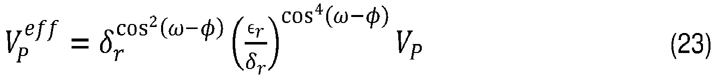
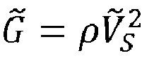
- curve 830 shows the result of isotropic modeling with the effective elastic parameters specified in the table under the graph, where V P eff , V S eff and ⁇ eff are the anisotropic elastic primary wave velocity, shear wave velocity and density, respectively, calculated from the transform expressions (51), (52) and (53). The results show that isotropic modeling with the effective elastic parameters closely approximates anisotropic modeling.
- Figure 9 illustrates the similar results as the ones in Figure 8 (i.e., curve 910 is the anisotropic response, curve 920 is the isotropic response and curve 930 is the result of isotropic modeling with the effective elastic parameters), but for the orthorhombic anisotropy case.
- the effective elastic parameter values calculated with equations (14), (15) and (16) are shown in the table under the graph. Again, the results illustrate that isotropic modeling with the effective elastic parameters closely approximates anisotropic modeling.
- the equations (71) for orthorhombic and (72) for TTI cases show that the transform functions have parameters that control the transforms. In some cases, appropriate values for these transform parameters can be obtained analytically. However, in another embodiment, an iterative procedure can also be readily followed to obtain appropriate values for the transform parameters. This implies further important benefits such as: exact modeling methods rather than 3-term approximations can be used as reference for the case of the simple single flat interface model, or more complex modeling methods can be applied; and other transform functions with other functional forms and with other transform parameters than equations (71) and (72) can be applied to evaluate if a better approximation can be obtained.
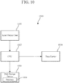
- FIG 10 is a block diagram of a seismic data processing apparatus 1000 according to an embodiment.
- Apparatus 1000 includes a CPU 1002, a data storage device 1004 (that may include a database 1006), and an interface 1008.
- Interface 1008 is configured to obtain seismic data acquired for the underground formation.
- the CPU is configured to perform methods similar to 600 and/or 700 described above.
- the CPU may include a software or hardware interface to a computer readable recording medium such as the data storage device 1004 or an external device.
- the computer readable recording medium stores executable codes, which, when executed by the CPU, make the CPU perform methods similar with 600 and 700 described above.
- Embodiments described in this section may perform in the context of an arbitrary stack of layers with different anisotropy types (e.g., orthorhombic, TTI, VTI and/or HTI).
- anisotropy types e.g., orthorhombic, TTI, VTI and/or HTI.
- the disclosed embodiments provide methods and systems for seismic exploration of an underground formation including an orthorhombic anisotropic medium or a TTI medium. It should be understood that this description is not intended to limit the invention. On the contrary, the embodiments are intended to cover alternatives, modifications and equivalents, which are included in the spirit and scope of the invention as defined by the appended claims. Further, in the detailed description of the embodiments, numerous specific details are set forth in order to provide a comprehensive understanding of the claimed invention. However, one skilled in the art would understand that various embodiments may be practiced without such specific details.
Landscapes
- Engineering & Computer Science (AREA)
- Remote Sensing (AREA)
- Physics & Mathematics (AREA)
- Life Sciences & Earth Sciences (AREA)
- Acoustics & Sound (AREA)
- Environmental & Geological Engineering (AREA)
- Geology (AREA)
- General Life Sciences & Earth Sciences (AREA)
- General Physics & Mathematics (AREA)
- Geophysics (AREA)
- Geophysics And Detection Of Objects (AREA)
Abstract
Description
- Embodiments of the subject matter disclosed herein generally relate to methods and devices for seismic data modeling and inversion for anisotropic media and, more particularly, to using isotropic-type processing with effective elastic parameter values based on anisotropy and elastic parameter values.
- Seismic data is routinely acquired to obtain information about subsurface structure, stratigraphy, lithology and fluids contained in underground formations (sometimes called simply "earth"). Seismic data is a term used for recordings of an underground structure's response to seismic waves (also called "acoustic waves"). The seismic waves are reflected in underground formations at locations of changes in earth properties that impact the seismic wave propagation.
- Modeling is used to gain understanding of seismic wave propagation and to help analyze seismic data. In modeling, seismic responses are estimated using models of earth properties and seismic wave propagation modeling algorithms. Models of earth properties are often specified in terms of physical parameters. For example, modeling methods are widely used to study changes in seismic reflection amplitudes with the changing angle of incidence of a plane wave reflecting from a flat interface as described in the article by Castagna, J. P., and Backus, M. M., "Offset-dependent reflectivity - Theory and practice of AVO analysis," published in Investigations in Geophysics Series No. 8, 1993, Society of Exploration Geophysicists (incorporated herewith by reference in its entirety). In this article, two half-spaces above and below an interface are assumed to be homogeneous and isotropic so that each half-space can be described with just three earth parameters, e.g., p-wave velocity, s-wave velocity and density. In practice, alternative triplets of parameters may be used, e.g., p-wave impedance, s-wave impedance and density. These parameters are referred to as elastic parameters. In some cases, modeling methods start from other earth parameters, and the transforms to elastic parameters are included as part of the modeling.
- In seismic modeling (often referred to as "forward modeling"), a source seismic wavelet may be used to model the earth response. In an opposite process to forward modeling called "inverse modeling" or "inversion," earth parameters are estimated based on the measured seismic responses, and an estimate of the source seismic wavelet. Inversion methods are generally based on forward models of seismic wave propagation, and some make use of some input elastic parameter data such as low frequency trend information or statistical distributions. Other inversion methods use some calibration of seismic amplitudes, performed in a pre-processing step or as part of an algorithm. Dependent on the seismic data acquisition geometries, estimates of earth properties obtained from the inversion methods are generally provided as a series of 2D sections or 3D volumes of elastic parameter values. Inversion is often followed by analysis and interpretation of the inversion results. Available borehole log measurements may be used during the analysis and interpretation.
- Local isotropy is a core assumption of most conventional methods for forward modeling, wavelet estimation, inversion, analysis and interpretation of inversion results, as well as analysis and interpretation of seismic data. Local isotropy assumption considers the earth (i.e., the underground formation) to be a stack of layers, with each layer being described by a physical parameter or property with the same value when measured in different directions. Such methods are referred to hereinafter as "isotropic" methods.
- In reality, the layers are generally anisotropic, with the acquired seismic data embedding the effects of anisotropy. Seismic data affected by the anisotropy is called "anisotropic seismic data." Earth parameters that describe anisotropy are referred to as anisotropy parameters. Anisotropy has to be taken into consideration in order to improve the accuracy of seismic modeling, wavelet estimation, inversion, and the analysis and interpretation of inversion results for anisotropic seismic data. Ruger's monography, "Reflection Coefficients and Azimuthal AVO Analysis in Anisotropic Media," Geophysical Monograph Series No. 10, Society of Exploration Geophysicists, and Thomsen's article, "Understanding Seismic Anisotropy in Exploration and Exploitation," published in Distinguished Instructor Series No. 5, Society of Exploration Geophysicists/European Association of Geoscientists and Engineers (incorporated herewith by reference in their entirety) describe some approaches for handling anisotropy.
- Taking into consideration anisotropy makes seismic processing mathematically and numerically more complex than similar isotropic methods. Modeling methods (such as wavelet estimation and certain types of seismic data analysis and interpretation) must also be expanded to incorporate the anisotropy parameters, which makes them more challenging to use. Moreover, from the inversion perspective, explicit incorporation of anisotropy parameters is difficult. Performing inversion for the elastic parameters from amplitude-variation with offset (AVO) seismic data is recognized to be a difficult problem for most seismic data acquisition geometries. If the anisotropy parameters are also included in inversion, the number of unknown values increases, making it even harder to find a solution. Adding more parameters and coping with such difficulties also complicates the analysis and interpretation of inversion results.
-
U.S. Patent No. 6,901,333 andWO 2015/014762 (which are incorporated herein by reference) describe techniques for generating anisotropic elastic parameters (here called effective elastic parameters for anisotropic medium) which are used in isotropic modeling and isotropic inversion algorithms in particular anisotropic media: vertically transverse isotropic (VTI) media, which possess polar anisotropy characteristics, and horizontally transverse isotropic (HTI) media, which possess azimuthal anisotropy characteristics. However, underground formations may not be characterized by HTI or VTI anisotropy, being instead tilted transverse isotropic (TTI) and/or orthorhombic anisotropy (which are more general anisotropy types than VTI and HTI). - There is a need to develop methods and devices that incorporate and generate anisotropic (effective) elastic parameters in seismic modeling, wavelet estimation, inversion and the like, as well as analysis and interpretations of results for seismic data acquired over azimuthally anisotropic media such as TTI and orthorhombic.
- Various embodiments for modeling and seismic data inversion related to underground formation including anisotropic media use effective elastic parameter values based on anisotropy and elastic parameter values. Take into consideration anisotropy effects in this manner allows an efficient and accurate processing for orthorhombic and tilted transverse isotropic (TTI) media. Not taking into consideration the anisotropy effects may cause a significant error in locating hydrocarbon reservoirs.
- According to an embodiment, there is a method for seismic exploration of an underground formation including an orthorhombic anisotropic medium. The method includes obtaining seismic data acquired for the underground formation, wherein the seismic data includes seismic amplitudes detected at plural values of an azimuth angle, ω-ϕ, of a source-receiver direction relative to a principal axis of the orthorhombic anisotropic medium. The method further includes calculating elastic parameter values and anisotropy parameter values related to the orthorhombic anisotropic medium based on the seismic data, and performing an isotropic-type processing technique using effective elastic parameter values calculated based on the elastic parameter values, the anisotropy parameter values, and the azimuth angle for the orthorhombic anisotropic medium. The isotropic-type processing technique leads to a quantitative model of the underground formation usable to locate hydrocarbon reservoirs.
- According to another embodiment, there is a method for seismic exploration of an underground formation including a tilted transverse isotropic, TTI, medium having a symmetry axis tilted at a tilt angle τ relative to a horizontal plane thereof. The method includes obtaining seismic data acquired for the underground formation, wherein the seismic data includes seismic amplitudes detected at plural values of an azimuth angle, ω-ϕ, of a source-receiver direction relative to a projection of the symmetry axis in a horizontal plane. The method further includes calculating elastic parameter values and anisotropy parameter values related to the TTI medium based on the seismic data, and performing an isotropic-type processing technique using effective elastic parameter values calculated based on the elastic parameter values, the anisotropy parameter values, the values of the azimuth angle and of the tilt angle for the TTI medium. The isotropic-type processing technique leads to a quantitative model of the underground formation usable to locate hydrocarbon reservoirs.
- According to yet another embodiment, there is a seismic data processing apparatus for exploration of an underground formation. The apparatus includes an interface configured to obtain seismic data acquired for the underground formation, wherein the seismic data includes seismic amplitudes detected at plural values of an azimuth angle, ω-ϕ, of a source-receiver direction relative to (1) a principal axis of the orthorhombic anisotropic medium if the underground formation includes an orthorhombic anisotropic medium, or (2) relative to a projection of a symmetry axis in a horizontal plane, if the underground formation includes a tilted transverse isotropic, TTI, medium having a symmetry axis tilted at a tilt angle τ relative to an isotropy plane thereof. The apparatus also includes a central processing unit connected to the interface and configured (A) to calculate elastic parameter values and anisotropy parameter values related to the orthorhombic anisotropic medium or to the TTI medium based on the seismic data, and (B) to perform an isotropic-type processing technique using effective elastic parameter values calculated based on the elastic parameter values, and the anisotropy parameter values and the azimuth angle. The isotropic-type processing technique leads to a quantitative model of the underground formation usable to locate hydrocarbon reservoirs, and the effective elastic parameter values depend also on the tilt angles for TTI medium.
- For a more complete understanding of the present inventive concept, reference is now made to the following descriptions taken in conjunction with the accompanying drawings, in which:
-
Figure 1 is an illustration of a seismic data acquisition system; -
Figure 2 schematically illustrates an HTI model with the asymmetry being caused by a system of vertical parallel cracks; -
Figure 3 schematically illustrates an orthorhombic model with the asymmetry being caused by two orthogonal systems of parallel cracks and thin horizontal layering; -
Figures 4A and 4B illustrate a VTI and a TTI model, respectively; -
Figure 5 illustrates an orthorhombic medium with orthogonal symmetry planes, having a horizontal symmetry plane (x1, x2) and the other two planes (x2,x3) and (x1,x3) being vertical; -
Figure 6 is a flowchart of a method for seismic exploration of an underground formation including an orthorhombic anisotropic medium according to an embodiment; -
Figure 7 is a flowchart of a method for seismic exploration of an underground formation including an orthorhombic anisotropic medium according to an embodiment; -
Figures 8 and9 are graphs illustrating results of applying methods according to embodiments; and -
Figure 10 is a block diagram of a seismic data processing apparatus according to an embodiment. - The following description of the exemplary embodiments refers to the accompanying drawings. The same reference numbers in different drawings identify the same or similar elements. The following detailed description does not limit the invention. Instead, the scope of the invention is defined by the appended claims. The following embodiments are discussed using the terminology of seismic data processing for exploring underground structures, which maximizes the information associated with parameter variations and extracted from seismic data acquired with a given set of source-receiver pairs.
- Reference throughout the specification to "one embodiment" or "an embodiment" means that a particular feature, structure or characteristic described in connection with an embodiment is included in at least one embodiment of the subject matter disclosed. Thus, the appearance of the phrases "in one embodiment" or "in an embodiment" in various places throughout the specification is not necessarily referring to the same embodiment. Further, the particular features, structures or characteristics may be combined in any suitable manner in one or more embodiments.
- Methods and devices that process seismic data taking into account the effects of anisotropy associated with tilted transverse isotropic (TTI) and orthorhombic media (i.e., subsurface layers being imaged which possess azimuthal anisotropy) according to various embodiments are describes in this section. In some embodiments, earth elastic and anisotropy parameters associated with TTI and orthorhombic media are converted into anisotropic parameters used in isotropic seismic data processing such as, but not limited to, seismic modeling, wavelet estimation, inversion, the analysis and interpretation of inversion results, and the analysis and interpretation of seismic data.
- Prior to discussing such embodiments in detail, consider
system 100 for land seismic data acquisition illustrated inFigure 1 . This system is configured to generate, transmit and receive seismic waves thereby exploring underground formations. Such exploration may determine the absence or presence of hydrocarbon deposits (such as 10 in sediment layer 12) or at least the probability of the absence or presence of hydrocarbon deposits underground. -
System 100 includes aseismic wave source 110, which may be a vibrator moved to different locations by the first vehicle/truck 112. The seismic source generates seismic waves. Some of the seismic waves' energy is detected by receivers 130 (e.g., geophones). The receivers convert the detected waves into electrical signals recorded by seismic data acquisition system 120 (which can be located, for example, on vehicle/truck 122).Source 110,receivers 130, anddata acquisition system 120 are placed onground surface 11 and are interconnected by one ormore cables 132. - In
Figure 1 , there is a single seismic source with a single vibrator, but more sources and vibrators may be used.Vehicle 122 may communicate wirelessly withvehicle 112 viaantenna Antenna 134 may facilitate wireless communications of the receivers withvehicles - Seismic waves generated by
source 110 propagate on theground surface 11 assurface wave 111 and underground as transmitted waves 116. The transmitted waves are partially reflected atinterface 13 betweenlayers 12 and 14 (which have different wave propagation properties) as reflected waves 118. The surface and the reflected waves may be detected byreceivers 130 that convert the detected seismic energy into an electrical signal. The electrical signal represents both reflected waves and surface waves, which are undesirable and filtered out as much as is practically possible during seismic data processing.Data acquisition system 120 samples the electrical signals, yielding a series of sample amplitude versus time, which is the seismic data. -
Figure 1 illustrates a linear land data acquisition. However, receivers may be placed on a survey area enabling data acquisition for different azimuth angles (i.e., different angles of source-receiver direction relative to a reference direction) as illustrated, for example, inU.S. Patent No. 9,791,578 - In marine environment, seismic data acquired with streamer spreads towed yields at least a narrow range of azimuth angles. This limited range may be extended by using an assembly of vessels as described, for example, in
U.S. Patent 9,482,773 -
Figure 2 illustrates an HTI medium with vertical fractures that are substantially parallel with an isotropy plane and substantially perpendicular to symmetry axes in a symmetry plane.Figure 3 illustrates an orthorhombic medium with two orthogonal systems of parallel fractures, thus having two vertical symmetry planes.Figures 2 and3 are adapted from 1997 article "Anisotropic parameters and P-wave velocity for orthorhombic media" by Tsvankin, I. published in Geophysics, vol. 62, no. 4, pp. 1292-1309. -
Figure 4A illustrates HTI andFigure 4B illustrates TTI. Different from HTI, in TTI the symmetry axis is tilted with respect to a horizontal plane by a given angle τ. -
Figure 5 illustrates another example of an anisotropic medium. The illustrated orthorhombic medium's anisotropy is caused by two orthogonal systems of vertical parallel cracks and also by a horizontal fine layering. For this medium, three symmetry planes are orthogonal to one another, with one symmetry plane being horizontal and the other two being vertical. Both TTI and orthorhombic media (also known as media with azimuthal anisotropy) are frequently associated with cracks, fractures and stress that occur in underground formations where regional differential horizontal stress is the dominant stratification factor. - In seismic data, important information about earth elastic and anisotropy parameters is embedded in the change of seismic amplitudes as a function of the separation between sources and receivers (a feature known as Amplitude Versus Offset AVO). AVO may be converted, for example, to angles for Amplitude Versus Angle (AVA) analysis and interpretation. Rather than studying the data at the level of records, partial stacks of records are sometimes used to reduce the amount of data and improve robustness while retaining the structural information embedded in the amplitude changes with offset, angle or other parameters.
- The link between the subsurface parameters and AVO is determined by seismic wave propagation modeling. For the most general case, this leads to a very complex relationship that can only be solved by numerical wave equation modeling. Most conventional modeling methods are based on a simplified wave propagation model. For example, the following assumption has been used to define a simplified seismic wave propagation model: the earth (i.e., underground formation) is stratified into isotropic parallel layers; seismic waves propagate as plane waves impinging on each interface at a constant angle; each interface acts as an independent reflector; transmission effects other than ray bending are neglected; and the calculated plane wave reflection coefficients assume that half-spaces above and below the reflector interface are isotropic. Even with this very simple model of the earth and of wave propagation, the resulting Zoeppritz equations that describe the AVO relationship are quite complex, making it necessary (for practical reasons) to approximate the Zoeppritz equations. The 3-term Aki-Richards, the 3-term Shuey (which is a rearrangement of the Aki-Richards equation) and 2-term Shuey approximations have been used to approximate the Zoeppritz equations. Conventional seismic AVO inversion methods are based on these forward modeling equations or the Zoeppritz equations.
- The following embodiments use effective elastic parameters for anisotropic medium. The effective elastic parameters, which are based on the anisotropy parameters and the elastic parameters, are used in the isotropic-type techniques applied to the seismic data. These effective elastic parameters take into consideration azimuthal anisotropy to an acceptable level of accuracy.
- It is well-known (as described, for example, in "Reflection Coefficients and Azimuthal AVO Analysis in Anisotropic Media," by Ruger, A. published in Geophysical ) how to incorporate anisotropy in AVO modeling (i.e., generalizing the isotropic modeling to model plane wave reflection in the case of anisotropic media). Similar to the approximation of the Zoeppritz equations by the 3-term Aki-Richards or Shuey equations, a convenient approximation to the AVO relationship can be obtained for the AVO plane wave reflection coefficients on a flat interface bounded by anisotropic half-spaces. The 3-term approximation of the Zoeppritz PP reflectivity is given by:

- The effective elastic parameters VP eff, VS eff,and ρeff are defined such that the PP reflectivity coefficients have an identical form to the isotropic media case of Aki-Richards (see Aki, K.T., and Richards, P.G., "Quantitative Seismology: Theory and Methods," Vol. 1, published in 1980 by W.H. Freeman and Co., page 153) when expressed in terms of the anisotropic elastic parameters:


- An expression for the PP reflectivity for orthorhombic medium is given by the following expressions:


V P andV s being the above and below averages across the interface for the reference velocities. Further, for the orthorhombic case


Table 1 Thomsen Parameter ε δ γ (x 2 ,x 3) plane 

(x 1 ,x 3) plane 
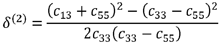
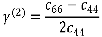
(x 1,x 2) plane 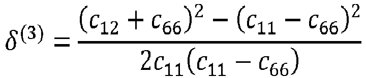

- The effective elastic parameters in orthorhombic media are derived in the following manner. From equation (7) for the curvature term R 4

- In the small contrast limit, integrating differential equations (11), (12) and (13) yield the following formulas for the anisotropic elastic parameters:


- Equivalent to equations (14), (15) and (16), effective elastic parameters in an orthorhombic case may use P-impedance (I P) and S-impedance (I S) in addition to density (ρ), for seismic inversion:


- Table 2 lists Thomsen parameters for the particular cases of HTI and VTI.
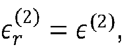
Thomsen parameter HTI VTI ε (1) 0 ε ≈ -ε (V) ε (2) ε (V) ε ≈ -ε (V) δ (1) 0 δ ≈ δ (V) - 2ε (V) δ (2) δ (V) δ ≈ δ (V) - 2ε (V) δ (3) δ (V) - 2ε (V)0 γ (2) γ(V) γ ≈ -γ (V) γ (3) - γ (V)0 - The substitution of HTI Thomsen parameters from Table 2 into the general expressions (8), (9) and (10) yields the following equations valid in the HTI case:


- Further substituting equations (20), (21) and (22) into the expressions (14), (15) and (16) gives for the effective elastic parameters in the HTI case:


- As in the orthorhombic case, the reflectivity expressions for TTI media (see
Figure 4 ) are derived from the general anisotropic expression for PP wave reflectivity.


VS /VP )2 withVS andVP being the above and below averages across the interface for the reference velocities. Further,

Figure 4 ). The functions ε*(τ, ϕ, ω), δ*(τ, ϕ, ω) and Γ* (τ, ϕ, ω) are similar to the ones in formula (8), (9) and (10) but also depend on the tilt angle τ. Note that here the ϕ is the azimuth angle of the projection of the symmetry axis in a horizontal plane.


- Formulas for the reflectivity coefficient were written by choosing the reference velocities within the isotropy plane. In turn, these formulas could be equivalently rewritten by choosing the reference P- and S- velocities along the anisotropic symmetry axis, by defining the so-called VTI reference system. In the VTI reference system, the reference p-wave


The functions ε*(τ̃, ϕ, ω), δ*(τ̃, ϕ, ω) and Γ* (τ̃, ϕ, ω) are given by formula similar with (34)-(39):


- Thus, the anisotropic effective elastic parameters for TTI media with VTI reference convention are:


- Effective elastic parameters in the TTI case may use P-impedance (I P) and S-impedance (I S) in addition to density (ρ), for seismic inversion, yielding the following formulas that are equivalent to equations (51), (52) and (53):


- In the particular case of VTI media τ̃ = 0 and therefore


- The final formula for the effective elastic parameters for VTI media (as previously presented in
U.S. Patent No. 6,901,333 ) are:


- Returning now to the effective elastic parameters in orthorhombic, any elastic parameter E has a corresponding effective elastic parameter Eeff expressed as:


- For the effective elastic parameters in TTI medium, any elastic parameter E has a corresponding effective elastic parameter Eeff expressed as:


- Alternatively, the above effective elastic parameters for both orthorhombic and TTI media may be expressed as:

- All of the above-derived formulas for effective elastic parameters are valid for arbitrary contrasts of azimuthal orientations for both orthorhombic and TTI anisotropy cases, and also valid for arbitrary contrast of tilt orientation for a TTI anisotropy case.
-
Figure 6 is a flowchart illustrating amethod 600 for seismic exploration of an underground formation including an orthorhombic anisotropic medium according to an embodiment. At 610,method 600 includes obtaining seismic data acquired for the underground formation, wherein the seismic data includes seismic amplitudes detected at plural values of an azimuth angle, ω-ϕ, of a source-receiver direction relative to a principal axis of the orthorhombic anisotropic medium.Method 600 further includes calculating elastic parameter values and anisotropy parameter values related to the orthorhombic anisotropic medium based on the seismic data at 620. The calculated values may include values for VP, VS∥, ρ, ε (1), ε (2), δ (1), δ (2), δ (3), γ (3), ω, ϕ. These values may be obtained via conventional seismic data processing, where offset and azimuth-dependent time shifts are indicative of changes in the propagation velocity. Additionally, at the position of the well borehole, one can perform additional seismic experiments to specifically recover TTI and/or orthorhombic parameters. Such experiments are known as walk-away and walk-around VSP (Vertical Seismic Profiling). -
Method 600 further includes performing an isotropic-type processing technique using effective elastic parameter values at 630. The effective elastic parameter values are calculated based on the elastic parameter values, the anisotropy parameter values, and the azimuth angle (as in equations (14), (15) and (16)). The isotropic-type processing technique leads to a quantitative model of the underground formation usable to locate hydrocarbon reservoirs. That is, the output of the isotropic-type processing technique is a quantitative model of the orthorhombic anisotropic medium within the orthorhombic anisotropic medium. - The isotropic-type processing technique may be an isotropic seismic modeling method, an isotropic seismic analysis and interpretation method, an isotropic seismic wavelet estimation method, an isotropic seismic inversion method, or an isotropic method for analysis and interpretation of inversion results to produce processed effective elastic parameter data.
- An elastic parameter E may have a corresponding effective elastic parameter Eeff expressed as in equation (71). Alternatively, a elastic parameter E may have a corresponding effective elastic parameter Eeff expressed as in equation (73). The elastic parameters values may represent p-wave velocity, s-wave velocity and density. Alternatively, the elastic parameters values may represent p-wave impedance, s-wave impedance and density.
-
Figure 7 is a flowchart illustrating amethod 700 for seismic exploration of an underground formation including a TTI medium having a symmetry axis tilted at a tilt angle τ relative to a horizontal plane thereof according to an embodiment.Method 700 includes obtaining seismic data acquired for the underground formation at 710. Here, the seismic data includes seismic amplitudes detected at plural values of an azimuth angle, ω-ϕ, of a source-receiver direction relative to a projection of the symmetry axis in the horizontal plane. -
Method 700 further includes calculating elastic parameter values and anisotropy parameter values related to the TTI medium based on the seismic data at 720. Step 720 is similar to step 620 ofmethod 600. The calculated values may include values for VP, VS∥,ρ, ε (V) , δ (V) , ω, ϕ, τ. -
Method 700 further includes performing an isotropic-type processing technique using effective elastic parameter values at 730. The effective elastic parameter values are calculated based on the elastic parameter values, the anisotropy parameter values, the values of the azimuth angle and of the tilt angle (equations (51), (52), (53)). As in the case ofmethod 600, the isotropic-type processing technique leads to quantitative model of the underground formation usable to locate hydrocarbon reservoirs. - The isotropic-type processing technique in
methods - Another embodiment is directed to a method for approximating anisotropic seismic modeling by applying isotropic seismic modeling. The method includes an initial step of inputting earth elastic parameter data and earth anisotropy parameter data for an area of interest. Next, the earth elastic parameter data is transformed to obtain effective elastic parameter data based on the earth anisotropy parameter data. Isotropic seismic modeling is then applied to the transformed effective elastic parameter data. The resulting modeled anisotropic seismic data is an approximation of seismic data obtained by a corresponding anisotropic seismic modeling. The processed anisotropic seismic data is then output. The method may further include a step of substituting the effective elastic parameter data for isotropic elastic parameter data to synthesize the anisotropic seismic data. The synthesized anisotropic seismic data may be used in an isotropic analysis and interpretation method for analysis and interpretation of the anisotropic seismic data. The area of interest may be imaged by acquisition of borehole data, wide azimuth (WAZ) data, three-dimension (3D) earth models, or four-dimensional (4D) earth models. This step of transforming may further include applying appropriate transform functions that convert the earth elastic parameter data and earth anisotropy parameter data to the effective elastic parameter data.
-
Figures 8 and9 illustrate modeling results for layers with relatively strong anisotropy contrasts.Figure 8 illustrates the effect of using the 3-term approximation for the Zoeppritz equations described above for TTI media, wherein curve 810 (thin line) shows the anisotropic response and curve 820 (thick line) shows the isotropic response. In addition, curve 830 (dotted line) shows the result of isotropic modeling with the effective elastic parameters specified in the table under the graph, where V P eff, V S eff and ρeff are the anisotropic elastic primary wave velocity, shear wave velocity and density, respectively, calculated from the transform expressions (51), (52) and (53). The results show that isotropic modeling with the effective elastic parameters closely approximates anisotropic modeling. -
Figure 9 illustrates the similar results as the ones inFigure 8 (i.e.,curve 910 is the anisotropic response,curve 920 is the isotropic response andcurve 930 is the result of isotropic modeling with the effective elastic parameters), but for the orthorhombic anisotropy case. The effective elastic parameter values calculated with equations (14), (15) and (16) are shown in the table under the graph. Again, the results illustrate that isotropic modeling with the effective elastic parameters closely approximates anisotropic modeling. - Thus, the graphs in
Figures 8 and9 show that the approximation of anisotropic modeling using the effective elastic parameters defined for orthorhombic and TTI media in isotropic modeling is accurate. - The equations (71) for orthorhombic and (72) for TTI cases show that the transform functions have parameters that control the transforms. In some cases, appropriate values for these transform parameters can be obtained analytically. However, in another embodiment, an iterative procedure can also be readily followed to obtain appropriate values for the transform parameters. This implies further important benefits such as: exact modeling methods rather than 3-term approximations can be used as reference for the case of the simple single flat interface model, or more complex modeling methods can be applied; and other transform functions with other functional forms and with other transform parameters than equations (71) and (72) can be applied to evaluate if a better approximation can be obtained.
-
Figure 10 is a block diagram of a seismicdata processing apparatus 1000 according to an embodiment.Apparatus 1000 includes aCPU 1002, a data storage device 1004 (that may include a database 1006), and aninterface 1008.Interface 1008 is configured to obtain seismic data acquired for the underground formation. The CPU is configured to perform methods similar to 600 and/or 700 described above. The CPU may include a software or hardware interface to a computer readable recording medium such as thedata storage device 1004 or an external device. The computer readable recording medium stores executable codes, which, when executed by the CPU, make the CPU perform methods similar with 600 and 700 described above. - Embodiments described in this section may perform in the context of an arbitrary stack of layers with different anisotropy types (e.g., orthorhombic, TTI, VTI and/or HTI).
- The disclosed embodiments provide methods and systems for seismic exploration of an underground formation including an orthorhombic anisotropic medium or a TTI medium. It should be understood that this description is not intended to limit the invention. On the contrary, the embodiments are intended to cover alternatives, modifications and equivalents, which are included in the spirit and scope of the invention as defined by the appended claims. Further, in the detailed description of the embodiments, numerous specific details are set forth in order to provide a comprehensive understanding of the claimed invention. However, one skilled in the art would understand that various embodiments may be practiced without such specific details.
- Although the features and elements of the present embodiments are described in the embodiments in particular combinations, each feature or element can be used alone without the other features and elements of the embodiments or in various combinations with or without other features and elements disclosed herein.
- This written description uses examples of the subject matter disclosed to enable any person skilled in the art to practice the same, including making and using any devices or systems and performing any incorporated methods. The patentable scope of the subject matter is defined by the claims, and may include other examples that occur to those skilled in the art. Such other examples are intended to be within the scope of the claims.
Claims (15)
- A method (600) for seismic exploration of an underground formation including an orthorhombic anisotropic medium, the method comprising:obtaining (610) seismic data acquired for the underground formation, wherein the seismic data includes seismic amplitudes detected at plural values of an azimuth angle, ω-ϕ, of a source-receiver direction relative to a principal axis of the orthorhombic anisotropic medium;calculating (620) elastic parameter values and anisotropy parameter values related to the orthorhombic anisotropic medium based on the seismic data; andperforming (630) an isotropic-type processing technique using effective elastic parameter values calculated based on the elastic parameter values, the anisotropy parameter values, and the azimuth angle for the orthorhombic anisotropic medium,wherein the isotropic-type processing technique leads to a quantitative model of the underground formation usable to locate hydrocarbon reservoirs.
- The method of claim 1, wherein the isotropic-type processing technique includes at least one of:an isotropic seismic modeling method,an isotropic seismic analysis and interpretation method,an isotropic seismic wavelet estimation method,an isotropic seismic inversion method, andan isotropic method for analysis and interpretation of inversion results to produce processed effective elastic parameter data.
- The method of claim 1, wherein an elastic parameter E has a corresponding effective elastic parameter Eeff expressed as:


- The method of claim 1, wherein an elastic parameter E has a corresponding effective elastic parameter Eeff expressed as:

- The method of claim 1, wherein the elastic parameters values represent p-wave velocity, s-wave velocity and density.
- The method of claim 1, wherein the elastic parameters values represent p-wave impedance, s-wave impedance and density.
- A method (700) for seismic exploration of an underground formation including a tilted transverse isotropic, TTI, medium having a symmetry axis tilted at a tilt angle τ relative to a horizontal plane thereof, the method comprising:obtaining (710) seismic data acquired for the underground formation, wherein the seismic data includes seismic amplitudes detected at plural values of an azimuth angle, ω-ϕ, of a source-receiver direction relative to a projection of the symmetry axis in a horizontal plane;calculating (720) elastic parameter values and anisotropy parameter values related to the TTI medium based on the seismic data; andperforming (730) an isotropic-type processing technique using effective elastic parameter values calculated based on the elastic parameter values, the anisotropy parameter values, the values of the azimuth angle and of the tilt angle for the TTI medium,wherein the isotropic-type processing technique leads to a quantitative model of the underground formation usable to locate hydrocarbon reservoirs.
- The method of claim 7, wherein the isotropic-type processing technique includes at least one of:an isotropic seismic modeling method,an isotropic seismic analysis and interpretation method,an isotropic seismic wavelet estimation method,an isotropic seismic inversion method, andan isotropic method for analysis and interpretation of inversion results to produce processed effective elastic parameter data.
- The method of claim 7, wherein any elastic parameter E has a corresponding effective elastic parameter Eeff expressed as:


- The method of claim 7, wherein an elastic parameter E has a corresponding effective elastic parameter Eeff expressed as:

- The method of claim 7, wherein the elastic parameters values represent p-wave velocity, s-wave velocity and density.
- The method of claim 7, wherein the elastic parameters values represent p-wave impedance, s-wave impedance and density.
- A seismic data processing apparatus (1000) for exploration of an underground formation, the apparatus comprising:an interface (1008) configured to obtain seismic data acquired for the underground formation, wherein the seismic data includes seismic amplitudes detected at plural values of an azimuth angle, ω-ϕ, of a source-receiver direction relative to (1) a principal axis of the orthorhombic anisotropic medium if the underground formation includes an orthorhombic anisotropic medium, or (2) relative to a projection of a symmetry axis in a horizontal plane, if the underground formation includes a tilted transverse isotropic, TTI, medium having a symmetry axis tilted at a tilt angle τ relative to an isotropy plane thereof; anda central processing unit (1002), CPU, which has one or more processors and is connected to the interface (1008), the CPU being configuredto calculate elastic parameter values and anisotropy parameter values related to the orthorhombic anisotropic medium or to the TTI medium based on the seismic data; andto perform an isotropic-type processing technique using effective elastic parameter values calculated based on the elastic parameter values, and the anisotropy parameter values and the azimuth angle,wherein the isotropic-type processing technique leads to a quantitative model of the underground formation usable to locate hydrocarbon reservoirs, andthe effective elastic parameter values depend also on the tilt angles for TTI medium.
- The seismic data processing apparatus of claim 13, wherein for the orthorhombic anisotropic medium, an elastic parameter E has a corresponding effective elastic parameter Eeff expressed as:


- The method of claim 13, wherein, for the TTI medium, any elastic parameter E has a corresponding effective elastic parameter Eeff expressed as:


Applications Claiming Priority (1)
| Application Number | Priority Date | Filing Date | Title |
|---|---|---|---|
| US16/531,726 US11828895B2 (en) | 2019-08-05 | 2019-08-05 | Methods and devices using effective elastic parameter values for anisotropic media |
Publications (1)
| Publication Number | Publication Date |
|---|---|
| EP3772665A1 true EP3772665A1 (en) | 2021-02-10 |
Family
ID=71728684
Family Applications (1)
| Application Number | Title | Priority Date | Filing Date |
|---|---|---|---|
| EP20305752.6A Pending EP3772665A1 (en) | 2019-08-05 | 2020-07-03 | Methods and devices using effective elastic parameter values for anisotropic media |
Country Status (3)
| Country | Link |
|---|---|
| US (1) | US11828895B2 (en) |
| EP (1) | EP3772665A1 (en) |
| CA (1) | CA3086064A1 (en) |
Families Citing this family (15)
| Publication number | Priority date | Publication date | Assignee | Title |
|---|---|---|---|---|
| CN115113273A (en) * | 2021-03-22 | 2022-09-27 | 中国石油化工股份有限公司 | Crack parameter determination method, device, equipment and storage medium |
| CN113341455B (en) * | 2021-06-24 | 2024-02-09 | 中国石油大学(北京) | Viscous anisotropic medium seismic wave numerical simulation method, device and equipment |
| CN113568045B (en) * | 2021-07-26 | 2022-11-11 | 中南大学 | Inversion method of TTI medium crack inclination angle |
| CN114488302B (en) * | 2022-01-25 | 2024-06-14 | 中南大学 | A method and system for predicting in-situ anisotropic geostress field |
| CN114755722B (en) * | 2022-03-07 | 2024-11-15 | 中国石油大学(华东) | Five-dimensional seismic inversion method for inclined orthotropic media |
| CN114924316B (en) * | 2022-06-24 | 2026-04-10 | 中国石油大学(北京) | A method for estimating the anisotropy parameters of VTI media based on seismic shear wave inversion. |
| CN116755148A (en) * | 2023-05-25 | 2023-09-15 | 山东省胜利油田地学开拓基金会 | Travel time inversion method of multi-directional reflected waves in orthotropic media |
| CN119535545B (en) * | 2023-08-29 | 2025-10-10 | 中国石油化工股份有限公司 | Prestack seismic synchronous inversion method and system for anisotropic parameters of VTI media |
| CN120178324A (en) * | 2023-12-19 | 2025-06-20 | 中国石油天然气股份有限公司 | A method and system for improving fracture prediction accuracy using OVT seismic data |
| CN117724154B (en) * | 2024-02-05 | 2024-04-30 | 中国石油大学(华东) | VTI medium parameter prediction method considering strong anisotropy characteristics |
| CN118707604B (en) * | 2024-08-27 | 2024-11-22 | 中国石油大学(华东) | Orthotropic medium azimuth seismic inversion method based on combined dimension reduction strategy |
| CN119355808B (en) * | 2024-10-30 | 2025-08-01 | 成都理工大学 | Shale reservoir geological engineering dual dessert earthquake identification method |
| CN119535588B (en) * | 2024-11-20 | 2025-09-23 | 中国石油天然气集团有限公司 | Method and apparatus for determining anisotropic media for seismic exploration |
| CN119199994B (en) * | 2024-12-02 | 2025-12-16 | 长江大学 | Joint inversion method, joint inversion device, storage medium and electronic equipment |
| CN119960023B (en) * | 2024-12-30 | 2025-08-05 | 中国石油大学(华东) | A step-by-step inversion method for orthotropic media based on the second-order derivative of elastic impedance |
Citations (4)
| Publication number | Priority date | Publication date | Assignee | Title |
|---|---|---|---|---|
| US6901333B2 (en) | 2003-10-27 | 2005-05-31 | Fugro N.V. | Method and device for the generation and application of anisotropic elastic parameters |
| WO2015014762A2 (en) | 2013-07-29 | 2015-02-05 | Cgg Services Sa | Method and device for the generation and application of anisotropic elastic parameters in horizontal transverse isotropic (hti) media |
| US9482773B2 (en) | 2013-06-19 | 2016-11-01 | Cgg Services Sa | Wide azimuth seismic data acquisition method and system with at least three streamer sets |
| US9791578B2 (en) | 2013-05-01 | 2017-10-17 | Cgg Services Sas | Apparatus and method for seismic data acquisition with simultaneous activation of clustered vibrators |
Family Cites Families (3)
| Publication number | Priority date | Publication date | Assignee | Title |
|---|---|---|---|---|
| US11237288B2 (en) * | 2016-03-30 | 2022-02-01 | Halliburton Energy Services, Inc. | Verifying measurements of elastic anisotropy parameters in an anisotropic wellbore environment |
| US12032110B2 (en) * | 2016-05-25 | 2024-07-09 | Schlumberger Technology Corporation | Elastic parameter estimation |
| US11243318B2 (en) * | 2017-01-13 | 2022-02-08 | Cgg Services Sas | Method and apparatus for unambiguously estimating seismic anisotropy parameters |
-
2019
- 2019-08-05 US US16/531,726 patent/US11828895B2/en active Active
-
2020
- 2020-07-03 EP EP20305752.6A patent/EP3772665A1/en active Pending
- 2020-07-07 CA CA3086064A patent/CA3086064A1/en active Pending
Patent Citations (5)
| Publication number | Priority date | Publication date | Assignee | Title |
|---|---|---|---|---|
| US6901333B2 (en) | 2003-10-27 | 2005-05-31 | Fugro N.V. | Method and device for the generation and application of anisotropic elastic parameters |
| US9791578B2 (en) | 2013-05-01 | 2017-10-17 | Cgg Services Sas | Apparatus and method for seismic data acquisition with simultaneous activation of clustered vibrators |
| US9482773B2 (en) | 2013-06-19 | 2016-11-01 | Cgg Services Sa | Wide azimuth seismic data acquisition method and system with at least three streamer sets |
| WO2015014762A2 (en) | 2013-07-29 | 2015-02-05 | Cgg Services Sa | Method and device for the generation and application of anisotropic elastic parameters in horizontal transverse isotropic (hti) media |
| US20150293245A1 (en) * | 2013-07-29 | 2015-10-15 | Cgg Services Sa | Method and device for the generation and application of anisotropic elastic parameters in horizontal transverse isotropic (hti) media |
Non-Patent Citations (9)
| Title |
|---|
| "Distinguished Instructor Series Λ/ο. 5", EUROPEAN ASSOCIATION OF GEOSCIENTISTS AND ENGINEERS, article "Understanding Seismic Anisotropy in Exploration and Exploitation" |
| AKI, K.T.RICHARDS, P.G.: "Quantitative Seismology: Theory and Methods", vol. 1, 1980, W.H. FREEMAN AND CO., pages: 153 |
| CASTAGNA, J. P.BACKUS, M. M.: "Investigations in Geophysics Series Λ/ο. 8", 1993, SOCIETY OF EXPLORATION GEOPHYSICISTS, article "Offset-dependent reflectivity — Theory and practice of AVO analysis" |
| ERIC DUVENECK AND PETER M BAKKER: "Stable P-wave modeling for reverse-time migration in tilted TI media", GEOPHYSICS, SOCIETY OF EXPLORATION GEOPHYSICISTS, US, vol. 76, no. 2, 1 March 2011 (2011-03-01), pages S65 - S75, XP001574308, ISSN: 0016-8033, [retrieved on 20110310], DOI: 10.1190/1.3533964 * |
| FENG ZHANG ET AL: "Generalized approximations of reflection coefficients in orthorhombic media", JOURNAL OF GEOPHYSICS AND ENGINEERING, INSTITUTE OF PHYSICS PUBLISHING, BRISTOL, GB, vol. 10, no. 5, 25 September 2013 (2013-09-25), pages 54004, XP020251733, ISSN: 1742-2140, [retrieved on 20130925], DOI: 10.1088/1742-2132/10/5/054004 * |
| RÜGER A: "Variation of P-wave reflectivity with offset and azimuth in anisotropic media", GEOPHYSICS, SOCIETY OF EXPLORATION GEOPHYSICISTS, US, vol. 63, no. 3, 1 May 1998 (1998-05-01), pages 935 - 947, XP002326797, ISSN: 0016-8033, DOI: 10.1190/1.1444405 * |
| RUGER, A.: "Geophysical Monograph Series Λ/ο. 10", 2002, SOCIETY OF EXPLORATION GEOPHYSICISTS, article "Reflection Coefficients and Azimuthal AVO Analysis in Anisotropic Media" |
| TSVANKIN, I.: "Anisotropic parameters and P-wave velocity for orthorhombic media", GEOPHYSICS, vol. 62, no. 4, pages 1292 - 1309, XP002238921, DOI: 10.1190/1.1444231 |
| Y IVANOV ET AL: "Weak-anisotropy Approximation for P-wave Reflection Coefficient at the Boundary between Two TTI Media", 4 June 2015 (2015-06-04), pages 1 - 4, XP055757601, Retrieved from the Internet <URL:https://www.earthdoc.org/docserver/fulltext/2214-4609/2015/We_N110_03.pdf?expires=1607377575&id=id&accname=fromqa185&checksum=E610112512CDA33429A0D63582BEBC4B> [retrieved on 20201207] * |
Also Published As
| Publication number | Publication date |
|---|---|
| US11828895B2 (en) | 2023-11-28 |
| CA3086064A1 (en) | 2021-02-05 |
| US20210041587A1 (en) | 2021-02-11 |
Similar Documents
| Publication | Publication Date | Title |
|---|---|---|
| US11828895B2 (en) | Methods and devices using effective elastic parameter values for anisotropic media | |
| EP3028071B1 (en) | Method and device for the generation and application of anisotropic elastic parameters in horizontal transverse isotropic (hti) media | |
| US8352190B2 (en) | Method for analyzing multiple geophysical data sets | |
| US6826484B2 (en) | 3D prestack time migration method | |
| US6901333B2 (en) | Method and device for the generation and application of anisotropic elastic parameters | |
| US7355923B2 (en) | Seismic analysis using post-imaging seismic anisotropy corrections | |
| US6839658B2 (en) | Seismic processing with general non-hyperbolic travel-time corrections | |
| EP2483712B1 (en) | Method of exploration for hydrocarbons based on ava analysis, computer program product and computer apparatus | |
| US6263284B1 (en) | Selection of seismic modes through amplitude characteristics | |
| US7082368B2 (en) | Seismic event correlation and Vp-Vs estimation | |
| EP3094992B1 (en) | Velocity model building for seismic data processing using pp-ps tomography with co-depthing constraint | |
| US7315783B2 (en) | Traveltime calculation in three dimensional transversely isotropic (3D TI) media by the fast marching method | |
| US20030021184A1 (en) | Extraction of P-wave and S-wave velocities from multi-component seismic data by joint velocity inversion | |
| US11867856B2 (en) | Method and system for reflection-based travel time inversion using segment dynamic image warping | |
| US20060023569A1 (en) | Method and constructing a model of a heterogeneous medium described by several parameters from data expresed in different time scales | |
| US11604299B2 (en) | Mixed-phase source wavelet estimation from recorded seismic data | |
| US11320554B2 (en) | Method and system that uses an anisotropy parameter to generate high-resolution time-migrated image gathers for reservoir characterization, and interpretation | |
| Leaney et al. | Sub-salt velocity prediction with a look-ahead AVO walkaway | |
| Uren et al. | Anisotropic wave propagation and zero-offset migration | |
| EP2796899A2 (en) | Seismic data processing and apparatus | |
| Scott Leaney | AVO and anisotropy from logs and walkaways | |
| Droujinine | Sub‐basalt decoupled walkaway VSP imaging | |
| Mahmoudian et al. | AVAZ inversion for anisotropy parameters of a fractured medium: a physical modeling study | |
| van der Hilst et al. | Wave-Equation Reflection Tomography: Annihilators and Sensitivity Kernals |
Legal Events
| Date | Code | Title | Description |
|---|---|---|---|
| PUAI | Public reference made under article 153(3) epc to a published international application that has entered the european phase |
Free format text: ORIGINAL CODE: 0009012 |
|
| STAA | Information on the status of an ep patent application or granted ep patent |
Free format text: STATUS: THE APPLICATION HAS BEEN PUBLISHED |
|
| AK | Designated contracting states |
Kind code of ref document: A1 Designated state(s): AL AT BE BG CH CY CZ DE DK EE ES FI FR GB GR HR HU IE IS IT LI LT LU LV MC MK MT NL NO PL PT RO RS SE SI SK SM TR |
|
| AX | Request for extension of the european patent |
Extension state: BA ME |
|
| STAA | Information on the status of an ep patent application or granted ep patent |
Free format text: STATUS: REQUEST FOR EXAMINATION WAS MADE |
|
| 17P | Request for examination filed |
Effective date: 20210723 |
|
| RBV | Designated contracting states (corrected) |
Designated state(s): AL AT BE BG CH CY CZ DE DK EE ES FI FR GB GR HR HU IE IS IT LI LT LU LV MC MK MT NL NO PL PT RO RS SE SI SK SM TR |
|
| STAA | Information on the status of an ep patent application or granted ep patent |
Free format text: STATUS: EXAMINATION IS IN PROGRESS |
|
| 17Q | First examination report despatched |
Effective date: 20220805 |