EP3094992B1 - Velocity model building for seismic data processing using pp-ps tomography with co-depthing constraint - Google Patents
Velocity model building for seismic data processing using pp-ps tomography with co-depthing constraint Download PDFInfo
- Publication number
- EP3094992B1 EP3094992B1 EP15711564.3A EP15711564A EP3094992B1 EP 3094992 B1 EP3094992 B1 EP 3094992B1 EP 15711564 A EP15711564 A EP 15711564A EP 3094992 B1 EP3094992 B1 EP 3094992B1
- Authority
- EP
- European Patent Office
- Prior art keywords
- depthing
- seismic data
- data
- seismic
- constraints
- Prior art date
- Legal status (The legal status is an assumption and is not a legal conclusion. Google has not performed a legal analysis and makes no representation as to the accuracy of the status listed.)
- Active
Links
- 238000003325 tomography Methods 0.000 title claims description 29
- 238000012545 processing Methods 0.000 title claims description 24
- 238000000034 method Methods 0.000 claims description 75
- 230000008569 process Effects 0.000 claims description 36
- 238000001914 filtration Methods 0.000 claims 2
- 239000010410 layer Substances 0.000 description 29
- 238000013508 migration Methods 0.000 description 29
- 230000005012 migration Effects 0.000 description 17
- 239000002356 single layer Substances 0.000 description 9
- 238000013459 approach Methods 0.000 description 7
- 230000001427 coherent effect Effects 0.000 description 7
- 238000005457 optimization Methods 0.000 description 6
- 230000015572 biosynthetic process Effects 0.000 description 5
- 238000007796 conventional method Methods 0.000 description 4
- 238000003384 imaging method Methods 0.000 description 4
- 238000013507 mapping Methods 0.000 description 3
- 238000004458 analytical method Methods 0.000 description 2
- 238000004364 calculation method Methods 0.000 description 2
- 230000001419 dependent effect Effects 0.000 description 2
- 238000010586 diagram Methods 0.000 description 2
- 238000006073 displacement reaction Methods 0.000 description 2
- 238000009499 grossing Methods 0.000 description 2
- 230000007246 mechanism Effects 0.000 description 2
- 238000003908 quality control method Methods 0.000 description 2
- 239000013598 vector Substances 0.000 description 2
- 230000006978 adaptation Effects 0.000 description 1
- 230000003044 adaptive effect Effects 0.000 description 1
- 230000009286 beneficial effect Effects 0.000 description 1
- 238000004422 calculation algorithm Methods 0.000 description 1
- 230000000295 complement effect Effects 0.000 description 1
- 238000004590 computer program Methods 0.000 description 1
- 238000012937 correction Methods 0.000 description 1
- 238000013016 damping Methods 0.000 description 1
- 238000007405 data analysis Methods 0.000 description 1
- 230000001934 delay Effects 0.000 description 1
- 230000009189 diving Effects 0.000 description 1
- 230000000694 effects Effects 0.000 description 1
- 238000012854 evaluation process Methods 0.000 description 1
- 238000002474 experimental method Methods 0.000 description 1
- 238000013213 extrapolation Methods 0.000 description 1
- 230000010354 integration Effects 0.000 description 1
- 239000011159 matrix material Substances 0.000 description 1
- 230000001902 propagating effect Effects 0.000 description 1
- 238000002310 reflectometry Methods 0.000 description 1
- 238000012552 review Methods 0.000 description 1
- 239000011435 rock Substances 0.000 description 1
- 230000002123 temporal effect Effects 0.000 description 1
Images


Classifications
-
- G—PHYSICS
- G01—MEASURING; TESTING
- G01V—GEOPHYSICS; GRAVITATIONAL MEASUREMENTS; DETECTING MASSES OR OBJECTS; TAGS
- G01V1/00—Seismology; Seismic or acoustic prospecting or detecting
- G01V1/28—Processing seismic data, e.g. analysis, for interpretation, for correction
- G01V1/282—Application of seismic models, synthetic seismograms
-
- G—PHYSICS
- G01—MEASURING; TESTING
- G01V—GEOPHYSICS; GRAVITATIONAL MEASUREMENTS; DETECTING MASSES OR OBJECTS; TAGS
- G01V1/00—Seismology; Seismic or acoustic prospecting or detecting
- G01V1/28—Processing seismic data, e.g. analysis, for interpretation, for correction
- G01V1/30—Analysis
- G01V1/303—Analysis for determining velocity profiles or travel times
-
- G—PHYSICS
- G01—MEASURING; TESTING
- G01V—GEOPHYSICS; GRAVITATIONAL MEASUREMENTS; DETECTING MASSES OR OBJECTS; TAGS
- G01V2210/00—Details of seismic processing or analysis
- G01V2210/50—Corrections or adjustments related to wave propagation
- G01V2210/59—Other corrections
-
- G—PHYSICS
- G01—MEASURING; TESTING
- G01V—GEOPHYSICS; GRAVITATIONAL MEASUREMENTS; DETECTING MASSES OR OBJECTS; TAGS
- G01V2210/00—Details of seismic processing or analysis
- G01V2210/60—Analysis
- G01V2210/62—Physical property of subsurface
- G01V2210/622—Velocity, density or impedance
- G01V2210/6222—Velocity; travel time
Definitions
- Embodiments of the subject matter disclosed herein generally relate to methods and systems for seismic image acquisition and, more particularly, to mechanisms and techniques for generating velocity models used in seismic data processing.
- Seismic data acquisition and processing techniques are used to generate a profile (image) of a geophysical structure (subsurface) of the strata underlying the land surface or seafloor.
- seismic data acquisition involves the generation of elastic waves and the collection of reflected/refracted versions of those elastic waves to generate the image.
- This image does not necessarily provide an accurate location for oil and gas reservoirs, but it may suggest, to those trained in the field, the presence or absence of oil and/or gas reservoirs.
- providing a more accurate image of the subsurface, and preferably in a shorter period of time is an ongoing process in the field of seismic surveying.
- a significant challenge in land and marine-based seismic data analysis involves how to build a velocity model of the subsurface which is being imaged.
- building a velocity model for depth imaging becomes even more challenging when using multicomponent receivers to record the wave energy, e.g., receivers using hydrophones, geophones and/or accelerometers, since such multicomponent data requires two data sets to be processed, i.e., pressure or primary waves (P-waves and PP data) and converted or shear waves (S-waves and PS data), to build the model.
- P-waves and PP data pressure or primary waves
- S-waves and PS data converted or shear waves
- Such multicomponent data is frequently generated from ocean bottom cable (OBC) or ocean bottom node (OBN) acquisitions.
- PP reflections and PS wave reflections are usually processed separately to produce two complementary images.
- the PP image is obtained by mapping the recorded energy using wave field modelling in the P-wave velocity model from both the source and the receiver side; on the other hand, PS images are constructed by modelling a P- wave on the source side and mapping the reflections using the S- wave velocity model for wave field modelling.
- the two images are generally different: they represent the different reflectivity of P- and S- converted waves, they have different frequency content and spatial resolution, and they are affected differently by attenuation.
- the position of the main reflectors and interfaces in the two images should in most cases almost coincide when the velocity models used for imaging are accurate.
- Co-depthing refers to the process of correcting the P- and S- wave velocity models by constraining the depth of the events to the same, or close to the same, spatial location.
- the P-velocity model is built first using conventional techniques associated with single component, e.g., streamer acquisition, data.
- a first approximation of the S-velocity model is built at step 102.
- PS data can be migrated at step 104 to produce a PS depth image. From this image the PS residual moveouts (RMOs) can be evaluated and used to update the S-velocity model at step 106.
- RMOs PS residual moveouts
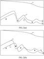
- a typical way to update the velocity model at step 106 involves using a 1-D approximation (co-depthing) which assumes that the PS horizon 200 is consistently shallower or deeper than the PP horizon 202 (i.e., assuming there is a consistent velocity bias between the two horizons) as exemplified by Figure 2(a) , where 204 indicates the free surface, e.g., ocean surface. If this assumption holds, then the 1-D approximation can improve the S-velocity model.
- methods and systems for jointly inverting PP and PS seismic data, estimating P and S propagation attributes (such as P and S velocity and the anisotropy parameters of the media through which the waves are propagating) while also adhering to one or more co-depthing constraints in a multi-layer nonlinear tomography process are described.
- the one or more co-depthing constraints involve minimizing the discrepancies between kinematically re-migrated seismic reflectors in the PP and PS domains and/or honoring predetermined volumetric warping (matching 3D time delays) or Vp/Vs ratio information: from now on, warping or Vp/Vs ratio information will be referred to collectively as Vp/Vs ratio information.
- Vp/Vs ratio information Different embodiments will be described below for each of these constraints.
- the techniques associated with these embodiments involve, among other things, kinematical repositioning (for example through map-migration) of PP and PS main reflectors that preserves travel time, thus ensuring an accurate match with re-migrated seismic data.
- the joint inversion can estimate distinct propagation parameters for all layers as part of a common P and S multi-layer velocity model.
- the focusing and positioning of all inverted pieces of the PP and PS reflectors can be predicted in an updated velocity model and displayed for quality control (QC) purposes in the form of migrated facets, i.e., locally coherent events.
- QC quality control
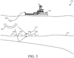
- a marine seismic data acquisition system 310 includes a ship 302 towing one or more sources, e.g., airguns, 304 for generating elastic waves 306.
- Receivers 308 are disposed on the ocean floor 310 and linked together via a cable 312.
- the elastic waves 306 generated by the source(s) 304 propagate downward, reflect off of, and penetrate (refract in) the ocean floor 310, wherein the refracted waves eventually are reflected by one or more reflecting structures (e.g., subsurface layer 314) back to the ocean floor's surface as the P and S waves mentioned in the Background section above.
- the reflected P and S waves then propagate upward and are detected by the receivers 308 disposed on the ocean floor 310 to, for example, which record the waves to generate the two data sets described above when the receivers 308 include multicomponent elements.
- This process is generally referred to as "shooting" a particular seafloor area, with the seafloor area referred to as a "cell” and the sea surface referred to as a "free surface.”
- Figure 3 shows, as an example, an ocean bottom cable type of marine seismic acquisition system
- the present invention is not limited to the processing of seismic data acquired via such systems and can be applied to seismic data acquired via other types of acquisition systems, e.g., land-based seismic acquisition systems, ocean bottom node (OBN) systems, or a combination of streamer-based acquisition systems and OBC/OBN systems.
- OBC/OBN systems e.g., a combination of streamer-based acquisition systems and OBC/OBN systems.
- the data associated with the received seismic elastic waves is subsequently processed to, for example, generate an image of the subsurface for review by experts to identify potential areas where natural resources may be located.
- this processing typically involves a number of different steps or subtypes of processing including, for example, one or more of deconvolution, gathering, stacking, velocity model building and migration. Of particular significance for this particular application is velocity model building.
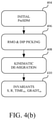
- the inputs to the process 400 shown in Figure 4(a) are various invariant values S, R, TIME SR , and GRADT SR at input block 402.
- the invariants input at 402 are combinations of model independent data (typically source and receiver positions (S and R), two-way traveltimes (TIME SR ) and traveltime slopes (GRADT SR ) in acquisition spatial or redundancy directions) which characterize an observable locally coherent piece of a seismic reflector and can be generated as illustrated in Figure 4(b) .
- picking 406 and finite-offset de-migration 408 processes are applied to acquire the desired invariants for use in the RMO inversion of Figure 4(a) .
- the invariants based method makes it possible to start the workflow from different types of data, e.g., pre-migration time data, migrated time data or depth migrated data.
- the invariants based method also makes it possible to start the model estimation with any starting velocity model, whereas in conventional methods inverting data picked in the image domain, the starting model should be the migration model having served for computing the RMO data to be inverted.
- the invariants-based RMO inversion performs an update loop including steps 412-418 during which the velocity model is iteratively updated until the RMO is minimized at step 418.
- a kinematic forward modelling process of the inversion data is performed. This step can include, for example, kinematically re-migrating RMO invariants in the current model, resulting in new facet positions and new predicted RMOs.
- a cost function can be evaluated process box 414 by measuring discrepancies between observed data and data re-modelled in the current velocity model, e.g., the predicted RMOs.
- Step 416 is an inverse modelling step where model parameters are updated by solving a linearized system of equations built from the cost function output of step 414.
- Step 418 is a step wherein convergence of the inversion is tested: the iterative updating process in the update loop can stop if the objective function has reached a minimum (or similar value) or if the model update is becoming small enough.
- Output 420 indicates the final updated model/object after the iterative loop (including the forward+inverse modelling steps described above).
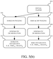
- Figure 5(a) shows another, more recent version of a nonlinear slope tomography for seismic data which has now been extended to be for a multi-layer velocity model.
- steps/processes which are the same or similar to those performed above with respect to the single layer nonlinear tomography of Figures 4(a) and 4(b) are labeled with the same reference numeral and their description is not repeated here for conciseness.
- the conventional multi-layer nonlinear tomography 500 again starts with, as its inputs, certain invariants represented by blocks 410 and 504.
- One way to establish the input invariants is shown in Figure 5(b) .
- the RMO invariants 410 are established in the same manner as described above with respect to Figure 4(b) and steps 404-410.
- the multi-layer process 500 uses horizon invariants 504 which are determined by performing horizon picking 506 on the initial preSDM data 404, and then performing kinematic de-migration 508 on the results from the horizon picking.
- step 510 of the multi-layer process of Figure 5(a) updates a multi-layer set of velocity attributes by solving a linear system of equations.
- the multi-layer process 500 also includes a step 512 involving repositioning of the horizons 512 using the horizon invariants and an output of the updated velocity attributes from step 510.
- the horizons of interest here are the horizons acting as layer boundaries in the multi-layer velocity model.
- Layer boundaries basically allow describing sharp velocity contrasts in the subsurface as the 3D grids describing the velocity attributes in each layer may have different values on both sides of a position sitting on layer boundary.
- the loop iterates until the RMO criterion is met at step 418 and then a final image (preSDM data) is output at 420.
- embodiments instead combine a joint PP-PS inversion which is constrained by co-depthing information with the afore-described invariant-based inversion to achieve a number of beneficial results in the processing of seismic data.
- co-depthing refers to the process of correcting the P- and S- wave velocity models by constraining the depth of the PP and PS events to the same spatial location.
- co-depthing applies to key interpreted horizons and/or to volumetrically picked locally coherent events that have been matched through warping.
- Warping is an existing mechanism by which elements s (i.e., locally coherent seismic events in this case) are related or associated from different 3D PP and PS images.
- Matching information resulting from warping referred to as volumetric Vp/Vs ratio feeds the inversion together with the RMO and other more conventional items such as regularization, structural smoothing, etc.
- embodiments simultaneously invert PP and PS RMO data together with optionally other data mentioned above (e.g., VSP, wells info, dip distortions, etc.) to enable simultaneously estimating P and S propagation attributes such as P and S velocity and/or Tilted Orthorhombic (TORT) anisotropy parameters.
- PS data refers to both forward and reverse PS information.
- the co-depthing constraint options provide additional benefits. For example, according to one embodiment, the discrepancies between kinematically re-migrated (zero-offset or finite offset) key seismic reflectors in PP and PS are minimized by adding an additional weighted term to the cost function which is used to update the multi-layer velocity attributes. Alternatively, or additionally, another co-depthing constraint minimizes volumetric Vp/Vs discrepancies between pseudo-observed Vp/Vs values and model values for each piece of a reflector in the subsurface by adding a different additional weighted term to the cost function. More detailed examples including these two exemplary co-depthing constraints will now be described with respect to Figures 6(a)-6(d) .
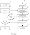
- Figure 6(a) depicts an example of combined non-linear slope tomography with joint PP-PS inversion 600 according to an embodiment.
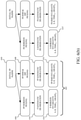
- Certain inputs to the process 600 are first determined as shown in Figure 6(b) based on the initial pre-stack depth migrated seismic data (PreSDM).
- the branch 602 begins with an initial P velocity model 604, which is subjected to pre-stack depth migration of the PP data.
- PreSDM refers to a technique whereby the recorded seismic events are re-located (migrated) in space relative to the location at which they were recorded since seismic receivers don't directly provide accurate depth information associated with the recorded seismic events.
- This PreSDM data is then subjected to both PP horizon picking 606 and PP RMO/Dip picking 608.
- Horizon picking refers to identifying (picking) e.g., locally coherent events on the seismic image associated with reflections and RMO (or dip) picking refers to a distortion/correction in the migration result which characterizes inaccuracies in the velocity model which was used to perform the migration.
- a kinematic map (depth) de-migration process 610, 612 is performed on both outputs to generate the desired P horizon invariants and the PP RMO invariants 614 and 616, respectively. Similar processing of the initial PS PreSDM is illustrated in Figure 6(b) to generate the S horizon invariants and the PS RMO invariants.
- both the PP and PS RMO invariants are used as inputs 618 to a kinematic re-migration process 620 which starts the update loop for this embodiment.
- this step involves a kinematic forward modelling inversion of the seismic data using the input PP and PS invariants which generates new facet positions of the seismic data and new predicted RMO values.
- this step can also involve re-migrating the PP-PS co-depthing data.
- the predicted RMO values from step 618, in addition to optional well formation tops input 621, are provided to the cost function evaluation process 622.
- a detailed example of a cost function which can be used in step 622 is provided below as equation (1).
- the cost function evaluates, among other things, the predicted RMO values (as in the multi-layer cost function 414) but also now the well and co-depthing mismatches as will be further described below.
- well formation tops input 621 refers to information that is derived from well analysis and contains space coordinates of formation tops which are key horizons in the subsurface.
- Well formation top information can also be extrapolated in between wells, in which case it is made of continuous horizons describing target formation tops.
- This information which is independent from Vp/Vs warping information, can be used to constrain (through an additional term in the cost function) the positioning of layer boundaries during the tomographic inversion.
- step 624 a linear update of the multi-layer velocity attributes is performed by solving a system of linear equations.
- Step 624 performs an inverse modelling process where model parameters are updated by solving a linearized system of equations built from the cost function of step 622.
- the system of equations to solve contains, in particular, equations that will contribute to the enforcement of PP-PS co-depthing.
- the attribute update performed in step 624 (usually involving both Vp and Vs model parameters) is now constrained by one or more co-depthing attributes by way of their usage in the cost function of step 622.
- co-depthing constraints are provided below.
- the P and/or S horizons are repositioned at step 626 using the P and/or S horizon invariants which were determined as shown in Figure 6(b) .
- the layer boundaries of the image associated with the seismic data i.e., the main horizons in the model
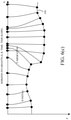
- map-migration using the just updated velocities, as part of the multi-layer approach. This process can, for example, be performed in two steps as shown in Figures 6(c) and 6(d) .
- reflection points associated with the horizon or layer boundary 650 are kinematically de-migrated using the previously determined (and stored) horizon invariants (P and/or S) based on a migration velocity (V migration ). Then, using an updated velocity (V update ), as shown in Figure 6(d) , the invariants are kinematically (map migration) migrated to a repositioned horizon 660 based on field of displacement vectors in a manner which preserves the morphology of the horizon or layer boundary.
- the repositioning of horizons in step 626 may be performed in different ways depending upon the desired implementation.
- the estimated position of a layer boundary in the velocity model is driven by reference reflecting information taken from either PP or PS data and that the purpose of the co-depthing constraint is to reconcile positions of reflectors in the PP and PS images.
- this objective can only be met (partially or totally) after the inversion.
- discrepancies can be observed.
- Those discrepancies affect in particular the position of the layer boundaries in the velocity model for which a choice must be made: either the boundary will stick to PP image or to PS image according to user's choice in which case either the P or S horizon invariants are supplied to block 626, respectively.
- the algorithm could have implemented another choice, for example an intermediate/average position between PP and PS images.
- the data can be checked to determine if a stopping criterion is met, e.g., if the RMO associated with the evaluated cost function is less than a given threshold or if the model update becomes sufficiently small, at step 628. Possible non convergence (usually caused by conflicting or erroneous data) can also be detected at step 628. If so, final pre-stack depth migrated data (image) is output at 630 and if not another iteration of the update loop is performed.
- the co-depthing constraint being applied in the linear update block 624 can, for example, be a reflector type of co-depthing constraint, i.e., where the discrepancies between kinematically re-migrated key seismic reflectors in PP and PS domains are minimized.
- a key reflector is a reflector that can be interpreted on both PP and PS images.
- the depth error between the PP or target/a priori horizon and the repositioned PS reflector are compared to seek a minimum depth error.
- An example of a misfit function to be minimized as part of the joint PP-PS processing which uses a reflector type of co-depthing constraint is illustrated in equation (1) below.
- Figure 6(a) describes one type of invariant-based inversion in which joint PP-PS inversion may be performed
- the inversion may also include the dip-constrained functionality described, for example, in U.S. Patent Application Serial No. 14/152,217 .
- the starting inversion can also contain one or more of well-tie data, VSP first or reflected arrivals, surface seismics refracted/diving arrivals and a-priori information (geological, geo-mechanical, rock properties...), etc., if desired for a particular implementation.
- volumetric co-depthing constraint can be used.
- volumetric Vp/Vs discrepancies between pseudo-observed Vp/Vs values and model values for each reflector in the subsurface are determined and used as a constraint on the tomography update.
- This volumetric co-depthing term is an additional weighted term provided to the cost function (an example of this is also provided below in equation (1).
- the initial Vp/Vs information typically derives from warped PP and PS N-dimensional images computed in various domains (such as a depth migrated domain, a time migrated domain or time pre-migration domain) which are closer to raw seismic observations, although according to another embodiment provided below the Vp/Vs information can be derived from stacked images directly in depth without image warping.
- This measured Vp/Vs ratio information can be mapped in, e.g., an invariants-like manner to less model-dependent data before being mapped again in the current depth model.
- a pseudo observed Vp/Vs ratio can be computed in the current velocity model at a given position and that pseudo observed Vp/Vs ration can then be compared to an actual Vp/Vs ratio computed at same position in the current velocity model.
- the Vp/Vs ratio in the current velocity model can be perturbed in order to minimize the discrepancies with the pseudo-observed Vp/Vs values which are recomputed at each internal inversion iteration.
- the cost function term according to this embodiment can, for example, be either a difference of Vp/Vs ratios or a difference of Vs values for a given, fixed Vp value or a vector field of distance or time differences between PP and PS events.
- This embodiment thus provides a kinematical repositioning (through map-migration or kinematic finite-offset migration for example) of PP and PS main reflectors and Vp/Vs ratio data that preserves traveltime, thus insuring a good match with re-migrated seismic data.
- the de-migration mapping processes typically require a structurally conformable dip model usually picked from migrated image stacks for describing the events to demigrate, not the velocity model in which those events will be demigrated.
- This equation can be used as the cost equation which is being minimized as part of the joint PP-PS inversion of Figure 6(a) , i.e., in step 622, although those skilled in the art will appreciate that this cost function is purely illustrative and that numerous other cost functions and variants of this cost function could be used depending upon the desired implementation.
- the estimation of the Vp/Vs ratio used in equation (1) is an important and challenging task in multicomponent seismic processing.
- the Vp/Vs ratio contains information about the lithology of the subsurface and is estimated from the recorded data.
- the Vp/Vs ratio can be derived from warped PP and PS N-dimensional images computed in various domains (such as a depth migrated domain, a time migrated domain or time pre-migration domain).
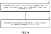
- an automatic method to perform image registration in the depth domain and, if the P-wave velocity model is assumed to be known, estimate the S-wave velocity from the data is described.
- the method involves, for example: the computation of matching filters between the PP and PS images at every lateral position; and the optimization of an objective function in order to minimize the non-zero lag coefficients of the matching filters.
- the matching filters are "do-nothing" filters (one non-zero sample at zero lag), then the two images are registered. This embodiment for determining the Vp/Vs ratio will now be described in more detail.
- the wave field-based registration problem associated with calculating the Vp/Vs ratio can be stated as follows.
- Two images of the subsurface can be constructed from PP and PS reflections by computing the zero-lag correlation between a modelled source wave field, w s , i p x t and the reconstructed receiver wave fields, w r , i p x t and w r , i s x t as:
- R pp x ⁇ i ⁇ 0 T dt w s , i p x t w s , i p x t ,
- R ps x ⁇ i ⁇ 0 T dt w s , i p x t w r , i p x t ,
- the superscript p , s indicates the type of wave
- the subscript s , r indicates the source or receiver side
- the index i spans the number
- This embodiment can measure the similarity between the two images using adaptive filters. If the two images have reflectors at the same location in space, then the filters that match the two images have energy clustered at zero lag.
- the gradient of the objective function in equation (8) can be computed using standard adjoint-state techniques and used to implement a local gradient-based optimization method to iteratively update (correct) the S-wave velocity model.
- the input images to the process can be preconditioned to increase the initial similarity in terms of frequency content and/or the images can be computed using shot-encoding techniques.
- the wave field extrapolation can be performed in the frequency domain or in mixed time-spatial wavenumber domains.
- the wave-equation used to model the wave fields can be fully elastic with arbitrary anisotropy.
- the parameters inverted in order to perform the registration can be the stiffness coefficients or a combination of the stiffness coefficients.
- the matching filters can be made variables in space (localized with windows in depth) and/or can be computed along the horizontal directions. Both P-wave and S-wave velocity models can be simultaneously updated.
- the matching can be performed on partial images (for example, images computed from different azimuths).
- this embodiment can be used to achieve co-depthing between the PP and PS images. Note that this usage can be independent of the embodiment of Figures 6(a)-6(d) associated with joint PP-PS inversion tomography. Second, assuming that the Vp model is inaccurate, this embodiment can then be used to modify the Vs model to achieve co-depthing, thus making the Vp/Vs ratio more accurate. This usage can be performed in conjunction with the embodiment of Figures 6(a)-6(d) to facilitate a more accurate constraint on the velocity attribute updates.
- this embodiment can be used to update both the Vp and Vs velocity models using only the co-depthing constraint as an optimization criteria, which usage can be independent of the embodiment of Figures 6(a)-6(d) .
- this latter embodiment's image registration technique can be performed without explicit calculation of Frechét matrices and does not require inversion of a system of linear equations since it is based on adjoint-state calculations.
- volumetric constraints in addition to, or as alternatives to, using the Vp/Vs ratio described above are also possible according to other embodiments associated with Figures 6(a)-6(d) .
- other volumetric information resulting from 1D,2D or 3D warping of PP and PS images can be used to generate a constraint term either in addition to the volumetric Vp/Vs term described above, or as an alternative thereto.
- PP and PS images can consist of partial image stacks in a given offset or angle range
- raw warped data can consist of a PS time cube, i.e., F(x, y, PP time), where converted PS time and PP time are, for example, vertical times, assuming that warping was done in the time domain and seismic data is obtained by converting depth migrated seismics to time using vertical group slowness.
- the local-type Vp/Vs constraint applied in the volumetrically sampled subsurface can be replaced by equations which preserve PS traveltime. Note that this embodiment assumes mild 3D update effects.
- Another 3D approach can involve warping of a PP stack cube with PS(h) constant offset/angle (or sub-offset range) cube which allows 3D finite-offset de-migration to obtain pseudo-model-independent tomography data, referred to herein as "invariants".
- the observed offset/angle dependent focusing error i.e., RMO slope
- the data cube computed by the warping process does not need to have all of its entries filled with values because all of the individual pieces of information in the cube are independent from each other, whereas in the earlier described volumetric constraint embodiment, the Vp/Vs ratio must have all of its values filled in.
- Figures 6(a)-6(d) depict various techniques for joint PP-PS inversion tomography with one or more co-depthing constraints according to embodiments, however those skilled in the art will appreciate that other such techniques can be derived by making adjustments thereto.
- such other embodiments can include different combinations of the type/list of data to invert, the list of velocity and horizon parameters to estimate and/or the constraints to be considered.
- the optimization process described herein can be linear or non-linear and can be local (through a gradient type optimization for example) or global (through a migration scan or stochastic approach) or a combination thereof.
- the local events to invert can be any type of locally coherent events, e.g., small portions of continuous reflectors described by spatial position and dip/slope data, that can be observed in common-offset, common-angle, common-receiver or common-shot collections/gathers of migrated seismic traces obtained, respectively, by any type of seismic migration, e.g. common-offset, common-shot or common-offset migration.
- a method for processing seismic data can include the step 800 of jointly inverting primary wave (PP) and shear wave (PS) seismic data as part of a nonlinear tomography process which adheres to one or more co-depthing constraints.
- PP primary wave
- PS shear wave
- the disclosed embodiments describe, for example, systems and methods for performing joint PP-PS inversion tomography with co-depthing constraint(s) on seismic data. It should be understood that this description is not intended to limit the invention. Further, in the detailed description of the exemplary embodiments, numerous specific details are set forth in order to provide a comprehensive understanding of the invention. However, one skilled in the art would understand that various embodiments may be practiced without such specific details.
Description
- The present application is related to, and claims priority from
U.S. Provisional Patent Application No. 61/926,449, filed January 13, 2014 - Embodiments of the subject matter disclosed herein generally relate to methods and systems for seismic image acquisition and, more particularly, to mechanisms and techniques for generating velocity models used in seismic data processing.
- Seismic data acquisition and processing techniques are used to generate a profile (image) of a geophysical structure (subsurface) of the strata underlying the land surface or seafloor. Among other things, seismic data acquisition involves the generation of elastic waves and the collection of reflected/refracted versions of those elastic waves to generate the image. This image does not necessarily provide an accurate location for oil and gas reservoirs, but it may suggest, to those trained in the field, the presence or absence of oil and/or gas reservoirs. Thus, providing a more accurate image of the subsurface, and preferably in a shorter period of time, is an ongoing process in the field of seismic surveying.
- The article by K. Broto et al. entitled "Anisotropic traveltime tomography for depth consistent imaging of PP and PS data", in Geophysics, vol. 22, No. 2, 1 February 2003, pages 114-119, discloses a method for processing seismic data.
- Document
US 2010/0177595 discloses using seismic attributes for data alignment and seismic inversion in joint PP/PS seismic analysis. - The article by Patrice Guillaume et al. entitled "Kinematic invariants: an efficient and flexible approach for velocity model building", in SEG Techincal Program Expanded Abstracts, 2008, 14 November 2008, pages 3687-3692, discloses a strategy for building depth velocity models from kinematic invariants.
- As will be appreciated by those skilled in the art, a significant challenge in land and marine-based seismic data analysis involves how to build a velocity model of the subsurface which is being imaged. In particular building a velocity model for depth imaging becomes even more challenging when using multicomponent receivers to record the wave energy, e.g., receivers using hydrophones, geophones and/or accelerometers, since such multicomponent data requires two data sets to be processed, i.e., pressure or primary waves (P-waves and PP data) and converted or shear waves (S-waves and PS data), to build the model. Not only does this result in more seismic data to be processed, but the processing also typically involves inverting for more parameters with the seismic data not being strongly cross-coupled with the extra parameters which are introduced, i.e., P data do not constrain the S velocity and S data only weakly constrains P data. Such multicomponent data is frequently generated from ocean bottom cable (OBC) or ocean bottom node (OBN) acquisitions.
- In multicomponent imaging, PP reflections and PS wave reflections are usually processed separately to produce two complementary images. The PP image is obtained by mapping the recorded energy using wave field modelling in the P-wave velocity model from both the source and the receiver side; on the other hand, PS images are constructed by modelling a P- wave on the source side and mapping the reflections using the S- wave velocity model for wave field modelling.
- The two images are generally different: they represent the different reflectivity of P- and S- converted waves, they have different frequency content and spatial resolution, and they are affected differently by attenuation. However, the position of the main reflectors and interfaces in the two images should in most cases almost coincide when the velocity models used for imaging are accurate. Co-depthing refers to the process of correcting the P- and S- wave velocity models by constraining the depth of the events to the same, or close to the same, spatial location.
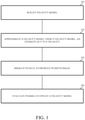
- A typical approach to building these velocity models is illustrated in the flow diagram of
Figure 1 . Therein, atstep 100, the P-velocity model is built first using conventional techniques associated with single component, e.g., streamer acquisition, data. Using the P-velocity model, along with an estimate of the P to S velocity ratio, well logs, and potentially other available information, a first approximation of the S-velocity model is built atstep 102. Using the first approximation of the S-velocity model, PS data can be migrated atstep 104 to produce a PS depth image. From this image the PS residual moveouts (RMOs) can be evaluated and used to update the S-velocity model atstep 106. - A typical way to update the velocity model at
step 106 involves using a 1-D approximation (co-depthing) which assumes that thePS horizon 200 is consistently shallower or deeper than the PP horizon 202 (i.e., assuming there is a consistent velocity bias between the two horizons) as exemplified byFigure 2(a) , where 204 indicates the free surface, e.g., ocean surface. If this assumption holds, then the 1-D approximation can improve the S-velocity model. However if this assumption is incorrect and, for example, thePS horizon 202 is displaced laterally from thePP horizon 200 as shown inFigure 2(b) and indicated by arrow in bold, then the 1D update approach will fail to produce a meaningful update to the S-velocity model. In addition to this problem, the 1-D approach inherently fails to consider 3D horizon displacements. - Accordingly, it would be desirable to provide systems and methods that avoid the afore-described problems and drawbacks associated with velocity model building as part of an overall seismic data processing scheme.
- Methods and systems for velocity modelling of seismic data, and techniques for estimating parameters associated with velocity modelling, are described which address the afore-described problems.
- According to an embodiment, there is provided a method for processing seismic data according to claim 1.
- According to an embodiment, there is provided a computer system for processing seismic data according to claim 7.
- The accompanying drawings, which are incorporated in and constitute a part of the specification, illustrate one or more embodiments and, together with the description, explain these embodiments. In the drawings:
-
Figure 1 is a flow diagram depicting a conventional technique for updating a velocity model associated with seismic data; -
Figures 2(a) and 2(b) illustrate a problem with an assumption associated with the conventional technique for updating a velocity model shown inFigure 1 ; -
Figure 3 shows an example of a marine seismic acquisition system which can be used to acquire seismic data that is processed according to an embodiment; -
Figures 4(a) and4(b) depict a conventional single layer nonlinear tomography process for seismic data; -
Figures 5(a) and5(b) show a conventional multi-layer nonlinear tomography process for seismic data; -
Figures 6(a) and6(b) depict a joint PP-PS inversion tomography process with co-depthing constraint according to an embodiment; -
Figures 6(c) and6(d) show steps associating with repositioning horizons in the embodiment ofFigures 6(a) and6(b) ; -
Figure 7 is a system for processing seismic data according to an embodiment; and -
Figure 8 is a flowchart illustrating a method for processing seismic data according to an embodiment. - The following description of the embodiments refers to the accompanying drawings. The same reference numbers in different drawings identify the same or similar elements. The following detailed description does not limit the invention. Instead, the scope of the invention is defined by the appended claims. Some of the following embodiments are discussed, for simplicity, with regard to the terminology and structure of marine seismic acquisitions. However, the embodiments to be discussed next are not limited to these configurations, but may be extended to other arrangements, e.g., land seismic acquisitions, as discussed later.
- Reference throughout the specification to "one embodiment" or "an embodiment" means that a particular feature, structure or characteristic described in connection with an embodiment is included in at least one embodiment of the subject matter disclosed. Thus, the appearance of the phrases "in one embodiment" or "in an embodiment" in various places throughout the specification is not necessarily referring to the same embodiment. Further, the particular features, structures or characteristics may be combined in any suitable manner in one or more embodiments.
- According to various embodiments, methods and systems for jointly inverting PP and PS seismic data, estimating P and S propagation attributes (such as P and S velocity and the anisotropy parameters of the media through which the waves are propagating) while also adhering to one or more co-depthing constraints in a multi-layer nonlinear tomography process are described. According to various embodiments the one or more co-depthing constraints involve minimizing the discrepancies between kinematically re-migrated seismic reflectors in the PP and PS domains and/or honoring predetermined volumetric warping (matching 3D time delays) or Vp/Vs ratio information: from now on, warping or Vp/Vs ratio information will be referred to collectively as Vp/Vs ratio information. Different embodiments will be described below for each of these constraints.
- The techniques associated with these embodiments involve, among other things, kinematical repositioning (for example through map-migration) of PP and PS main reflectors that preserves travel time, thus ensuring an accurate match with re-migrated seismic data. The joint inversion can estimate distinct propagation parameters for all layers as part of a common P and S multi-layer velocity model. When a nonlinear inversion is used according to some embodiments, the focusing and positioning of all inverted pieces of the PP and PS reflectors can be predicted in an updated velocity model and displayed for quality control (QC) purposes in the form of migrated facets, i.e., locally coherent events.
- In order to provide some context for the subsequent more detailed embodiments related to velocity modeling, consider first a seismic data acquisition process and system as will now be described with respect to
Figure 3 . InFigure 3 , a marine seismicdata acquisition system 310 includes aship 302 towing one or more sources, e.g., airguns, 304 for generatingelastic waves 306.Receivers 308 are disposed on theocean floor 310 and linked together via acable 312. Theelastic waves 306 generated by the source(s) 304 propagate downward, reflect off of, and penetrate (refract in) theocean floor 310, wherein the refracted waves eventually are reflected by one or more reflecting structures (e.g., subsurface layer 314) back to the ocean floor's surface as the P and S waves mentioned in the Background section above. The reflected P and S waves then propagate upward and are detected by thereceivers 308 disposed on theocean floor 310 to, for example, which record the waves to generate the two data sets described above when thereceivers 308 include multicomponent elements. This process is generally referred to as "shooting" a particular seafloor area, with the seafloor area referred to as a "cell" and the sea surface referred to as a "free surface." - Note that although
Figure 3 shows, as an example, an ocean bottom cable type of marine seismic acquisition system, the present invention is not limited to the processing of seismic data acquired via such systems and can be applied to seismic data acquired via other types of acquisition systems, e.g., land-based seismic acquisition systems, ocean bottom node (OBN) systems, or a combination of streamer-based acquisition systems and OBC/OBN systems. - The data associated with the received seismic elastic waves is subsequently processed to, for example, generate an image of the subsurface for review by experts to identify potential areas where natural resources may be located. As will be appreciated by those skilled in the art, this processing typically involves a number of different steps or subtypes of processing including, for example, one or more of deconvolution, gathering, stacking, velocity model building and migration. Of particular significance for this particular application is velocity model building.
- As a starting point for the more detailed discussion of the multi-layer nonlinear tomography embodiments mentioned above, consider first of all a conventional, single layer invariants-based residual moveout (RMO) non-linear tomography methodology illustrated in
Figure 4(a) and4(b) . This conventional, single layer invariants-based RMO inversion methodology is described inU.S. Patent No. 6,577,955 (hereafter the "955 patent"), and the interested reader is directed to the '955 patent for more details regarding this process. - Briefly, however, as the embodiments build upon this progression, the inputs to the
process 400 shown inFigure 4(a) are various invariant values S, R, TIMESR, and GRADTSR at input block 402. In this context the invariants input at 402 are combinations of model independent data (typically source and receiver positions (S and R), two-way traveltimes (TIMESR) and traveltime slopes (GRADTSR) in acquisition spatial or redundancy directions) which characterize an observable locally coherent piece of a seismic reflector and can be generated as illustrated inFigure 4(b) . Therein, using an initial migrated image of the recordedseismic data 404, i.e., the initial prestack depth migration data, picking 406 and finite-offsetde-migration 408 processes are applied to acquire the desired invariants for use in the RMO inversion ofFigure 4(a) . The invariants based method makes it possible to start the workflow from different types of data, e.g., pre-migration time data, migrated time data or depth migrated data. The invariants based method also makes it possible to start the model estimation with any starting velocity model, whereas in conventional methods inverting data picked in the image domain, the starting model should be the migration model having served for computing the RMO data to be inverted. - Returning to
Figure 4(a) , the invariants-based RMO inversion performs an update loop including steps 412-418 during which the velocity model is iteratively updated until the RMO is minimized atstep 418. Specifically, inblock 412, a kinematic forward modelling process of the inversion data is performed. This step can include, for example, kinematically re-migrating RMO invariants in the current model, resulting in new facet positions and new predicted RMOs. From the output ofstep 412, a cost function can be evaluatedprocess box 414 by measuring discrepancies between observed data and data re-modelled in the current velocity model, e.g., the predicted RMOs. Step 416 is an inverse modelling step where model parameters are updated by solving a linearized system of equations built from the cost function output ofstep 414. Step 418 is a step wherein convergence of the inversion is tested: the iterative updating process in the update loop can stop if the objective function has reached a minimum (or similar value) or if the model update is becoming small enough.Output 420 indicates the final updated model/object after the iterative loop (including the forward+inverse modelling steps described above). As mentioned above, those desiring more information regarding the processing of the seismic data indicated in the single layer, nonlinear tomography inversion described above with respect toFigures 4(a) and4(b) are referred to the above '955 patent. -
Figure 5(a) shows another, more recent version of a nonlinear slope tomography for seismic data which has now been extended to be for a multi-layer velocity model. Therein, those steps/processes which are the same or similar to those performed above with respect to the single layer nonlinear tomography ofFigures 4(a) and4(b) are labeled with the same reference numeral and their description is not repeated here for conciseness. - Therein the conventional multi-layer
nonlinear tomography 500 again starts with, as its inputs, certain invariants represented byblocks Figure 5(b) . Therein, theRMO invariants 410 are established in the same manner as described above with respect toFigure 4(b) and steps 404-410. However, additionally, themulti-layer process 500 useshorizon invariants 504 which are determined by performing horizon picking 506 on the initialpreSDM data 404, and then performingkinematic de-migration 508 on the results from the horizon picking. - Returning now to
Figure 5(a) , the update loops begins withkinematic re-migration 412 and evaluating acost function 414 using predicted RMO values output from the kinematic re-migration, as described above with respect toFigure 4(a) . However, unlikestep 416 in the single layer process ofFigure 4(a) ,step 510 of the multi-layer process ofFigure 5(a) updates a multi-layer set of velocity attributes by solving a linear system of equations. Moreover, themulti-layer process 500 also includes astep 512 involving repositioning of thehorizons 512 using the horizon invariants and an output of the updated velocity attributes fromstep 510. The horizons of interest here are the horizons acting as layer boundaries in the multi-layer velocity model. Layer boundaries basically allow describing sharp velocity contrasts in the subsurface as the 3D grids describing the velocity attributes in each layer may have different values on both sides of a position sitting on layer boundary. Again, as in the single layer version of this tomography, the loop iterates until the RMO criterion is met atstep 418 and then a final image (preSDM data) is output at 420. - With these examples of conventional single layer and multilayer non-linear tomography in mind, and as mentioned earlier, embodiments instead combine a joint PP-PS inversion which is constrained by co-depthing information with the afore-described invariant-based inversion to achieve a number of beneficial results in the processing of seismic data. As will be appreciated by those skilled in the art, co-depthing refers to the process of correcting the P- and S- wave velocity models by constraining the depth of the PP and PS events to the same spatial location. In this context co-depthing applies to key interpreted horizons and/or to volumetrically picked locally coherent events that have been matched through warping. Warping is an existing mechanism by which elements s (i.e., locally coherent seismic events in this case) are related or associated from different 3D PP and PS images. Matching information resulting from warping referred to as volumetric Vp/Vs ratio feeds the inversion together with the RMO and other more conventional items such as regularization, structural smoothing, etc. For example, embodiments simultaneously invert PP and PS RMO data together with optionally other data mentioned above (e.g., VSP, wells info, dip distortions, etc.) to enable simultaneously estimating P and S propagation attributes such as P and S velocity and/or Tilted Orthorhombic (TORT) anisotropy parameters. Note that, in this context, reference to PS data refers to both forward and reverse PS information.
- Additionally the co-depthing constraint options provide additional benefits. For example, according to one embodiment, the discrepancies between kinematically re-migrated (zero-offset or finite offset) key seismic reflectors in PP and PS are minimized by adding an additional weighted term to the cost function which is used to update the multi-layer velocity attributes. Alternatively, or additionally, another co-depthing constraint minimizes volumetric Vp/Vs discrepancies between pseudo-observed Vp/Vs values and model values for each piece of a reflector in the subsurface by adding a different additional weighted term to the cost function. More detailed examples including these two exemplary co-depthing constraints will now be described with respect to
Figures 6(a)-6(d) . -
Figure 6(a) depicts an example of combined non-linear slope tomography with joint PP-PS inversion 600 according to an embodiment. Certain inputs to theprocess 600 are first determined as shown inFigure 6(b) based on the initial pre-stack depth migrated seismic data (PreSDM). Therein, thebranch 602 begins with an initialP velocity model 604, which is subjected to pre-stack depth migration of the PP data. In this embodiment, as will be known by those skilled in the art, PreSDM refers to a technique whereby the recorded seismic events are re-located (migrated) in space relative to the location at which they were recorded since seismic receivers don't directly provide accurate depth information associated with the recorded seismic events. This PreSDM data is then subjected to both PP horizon picking 606 and PP RMO/Dip picking 608. Horizon picking refers to identifying (picking) e.g., locally coherent events on the seismic image associated with reflections and RMO (or dip) picking refers to a distortion/correction in the migration result which characterizes inaccuracies in the velocity model which was used to perform the migration. Aftersteps de-migration process PP RMO invariants Figure 6(b) to generate the S horizon invariants and the PS RMO invariants. - Returning to
Figure 6(a) , both the PP and PS RMO invariants are used asinputs 618 to akinematic re-migration process 620 which starts the update loop for this embodiment. As in the earlier discussed single layer and multi-layer nonlinear tomography processes ofFigures 4(a) and5(a) , respectively, this step involves a kinematic forward modelling inversion of the seismic data using the input PP and PS invariants which generates new facet positions of the seismic data and new predicted RMO values. However, unlike those earlier described processes, this step can also involve re-migrating the PP-PS co-depthing data. - The predicted RMO values from
step 618, in addition to optional well formation topsinput 621, are provided to the costfunction evaluation process 622. A detailed example of a cost function which can be used instep 622 is provided below as equation (1). However, as generally indicated inFigure 6(a) , the cost function evaluates, among other things, the predicted RMO values (as in the multi-layer cost function 414) but also now the well and co-depthing mismatches as will be further described below. As will be appreciated by those skilled in the art, well formation topsinput 621 refers to information that is derived from well analysis and contains space coordinates of formation tops which are key horizons in the subsurface. Well formation top information can also be extrapolated in between wells, in which case it is made of continuous horizons describing target formation tops. This information, which is independent from Vp/Vs warping information, can be used to constrain (through an additional term in the cost function) the positioning of layer boundaries during the tomographic inversion. - The process then proceeds to step 624 where a linear update of the multi-layer velocity attributes is performed by solving a system of linear equations. Step 624 performs an inverse modelling process where model parameters are updated by solving a linearized system of equations built from the cost function of
step 622. The system of equations to solve contains, in particular, equations that will contribute to the enforcement of PP-PS co-depthing. Thus, unlike the multi-layer velocity update performed instep 510 ofmethod 500, the attribute update performed in step 624 (usually involving both Vp and Vs model parameters) is now constrained by one or more co-depthing attributes by way of their usage in the cost function ofstep 622. Various examples of co-depthing constraints are provided below. - Next, the P and/or S horizons are repositioned at
step 626 using the P and/or S horizon invariants which were determined as shown inFigure 6(b) . In this step, the layer boundaries of the image associated with the seismic data (i.e., the main horizons in the model) are repositioned by map-migration using the just updated velocities, as part of the multi-layer approach. This process can, for example, be performed in two steps as shown inFigures 6(c) and6(d) . In the first step, shown inFigure 6(c) , reflection points associated with the horizon orlayer boundary 650 are kinematically de-migrated using the previously determined (and stored) horizon invariants (P and/or S) based on a migration velocity (Vmigration). Then, using an updated velocity (Vupdate), as shown inFigure 6(d) , the invariants are kinematically (map migration) migrated to a repositionedhorizon 660 based on field of displacement vectors in a manner which preserves the morphology of the horizon or layer boundary. - Note that the repositioning of horizons in
step 626 may be performed in different ways depending upon the desired implementation. Consider that the estimated position of a layer boundary in the velocity model is driven by reference reflecting information taken from either PP or PS data and that the purpose of the co-depthing constraint is to reconcile positions of reflectors in the PP and PS images. However, this objective can only be met (partially or totally) after the inversion. In the meantime discrepancies can be observed. Those discrepancies affect in particular the position of the layer boundaries in the velocity model for which a choice must be made: either the boundary will stick to PP image or to PS image according to user's choice in which case either the P or S horizon invariants are supplied to block 626, respectively. Alternatively, the algorithm could have implemented another choice, for example an intermediate/average position between PP and PS images. - After the horizons are repositioned at
step 626, the data can be checked to determine if a stopping criterion is met, e.g., if the RMO associated with the evaluated cost function is less than a given threshold or if the model update becomes sufficiently small, atstep 628. Possible non convergence (usually caused by conflicting or erroneous data) can also be detected atstep 628. If so, final pre-stack depth migrated data (image) is output at 630 and if not another iteration of the update loop is performed. - In the embodiment of
Figures 6(a)-6(d) , the co-depthing constraint being applied in thelinear update block 624 can, for example, be a reflector type of co-depthing constraint, i.e., where the discrepancies between kinematically re-migrated key seismic reflectors in PP and PS domains are minimized. In this context, a key reflector is a reflector that can be interpreted on both PP and PS images. For each position on the key reflector, the depth error between the PP or target/a priori horizon and the repositioned PS reflector (using kinematic migration) are compared to seek a minimum depth error. An example of a misfit function to be minimized as part of the joint PP-PS processing which uses a reflector type of co-depthing constraint is illustrated in equation (1) below. - While
Figure 6(a) describes one type of invariant-based inversion in which joint PP-PS inversion may be performed, other variations are also contemplated. For example, in addition to RMO and according to another embodiment, the inversion may also include the dip-constrained functionality described, for example, inU.S. Patent Application Serial No. 14/152,217 . Additionally, the starting inversion can also contain one or more of well-tie data, VSP first or reflected arrivals, surface seismics refracted/diving arrivals and a-priori information (geological, geo-mechanical, rock properties...), etc., if desired for a particular implementation. - Moreover, in addition to, constraining the joint PP-PS inversion using the reflector co-depthing described above, according to another embodiment a volumetric co-depthing constraint can be used. In this embodiment volumetric Vp/Vs discrepancies between pseudo-observed Vp/Vs values and model values for each reflector in the subsurface are determined and used as a constraint on the tomography update. This volumetric co-depthing term is an additional weighted term provided to the cost function (an example of this is also provided below in equation (1). The initial Vp/Vs information typically derives from warped PP and PS N-dimensional images computed in various domains (such as a depth migrated domain, a time migrated domain or time pre-migration domain) which are closer to raw seismic observations, although according to another embodiment provided below the Vp/Vs information can be derived from stacked images directly in depth without image warping. This measured Vp/Vs ratio information can be mapped in, e.g., an invariants-like manner to less model-dependent data before being mapped again in the current depth model. A pseudo observed Vp/Vs ratio can be computed in the current velocity model at a given position and that pseudo observed Vp/Vs ration can then be compared to an actual Vp/Vs ratio computed at same position in the current velocity model. The Vp/Vs ratio in the current velocity model can be perturbed in order to minimize the discrepancies with the pseudo-observed Vp/Vs values which are recomputed at each internal inversion iteration.
- The cost function term according to this embodiment can, for example, be either a difference of Vp/Vs ratios or a difference of Vs values for a given, fixed Vp value or a vector field of distance or time differences between PP and PS events. This embodiment thus provides a kinematical repositioning (through map-migration or kinematic finite-offset migration for example) of PP and PS main reflectors and Vp/Vs ratio data that preserves traveltime, thus insuring a good match with re-migrated seismic data. The de-migration mapping processes typically require a structurally conformable dip model usually picked from migrated image stacks for describing the events to demigrate, not the velocity model in which those events will be demigrated.
- To illustrate an embodiment where both a reflector co-depthing constraint and a volumetric co-depthing constraint are used, consider the following, exemplary cost equation (1) below.

- ▪ Zps: modelled depth of PS horizon
- ▪ Ztarget: pseudo-observed horizon depth (a priori or PP)
- ▪ VpVsmod: Vp/Vs ratio in current model at given position(x,y,z)
- ▪ VpVsobs: pseudo-observed Vp/Vs ratio at given position(x,y,z)
recomputed/remapped in current model from (soft a priori) volumetric field of Vp/Vs ratio resulting from warping of initial seismic images - ▪ Wcodepth_Refl = global weighting factor of reflector co-depthing term in cost function
- ▪ Wcodepth_Vol = global weighting factor of volumetric Vp/Vs ratio co-depthing term in cost function
- ▪ Wijkl = individual variable weights applied to elementary contributors (typically locally coherent events) to all terms (RMO, dip, co-depthing...) in cost function
- This equation can be used as the cost equation which is being minimized as part of the joint PP-PS inversion of
Figure 6(a) , i.e., instep 622, although those skilled in the art will appreciate that this cost function is purely illustrative and that numerous other cost functions and variants of this cost function could be used depending upon the desired implementation. - The estimation of the Vp/Vs ratio used in equation (1) is an important and challenging task in multicomponent seismic processing. The Vp/Vs ratio contains information about the lithology of the subsurface and is estimated from the recorded data. As noted above, the Vp/Vs ratio can be derived from warped PP and PS N-dimensional images computed in various domains (such as a depth migrated domain, a time migrated domain or time pre-migration domain). However, according to another embodiment, an automatic method to perform image registration in the depth domain and, if the P-wave velocity model is assumed to be known, estimate the S-wave velocity from the data, is described. The method involves, for example: the computation of matching filters between the PP and PS images at every lateral position; and the optimization of an objective function in order to minimize the non-zero lag coefficients of the matching filters. When the matching filters are "do-nothing" filters (one non-zero sample at zero lag), then the two images are registered. This embodiment for determining the Vp/Vs ratio will now be described in more detail.
- Generally, the wave field-based registration problem associated with calculating the Vp/Vs ratio can be stated as follows. Two images of the subsurface can be constructed from PP and PS reflections by computing the zero-lag correlation between a modelled source wave field,


- The wave fields are solutions of the wave-equations, i.e.:


- If both P- and S- wave velocity models are correct, then the positions of the reflectors in the two images will coincide, otherwise there will be a misalignment. This embodiment can measure the similarity between the two images using adaptive filters. If the two images have reflectors at the same location in space, then the filters that match the two images have energy clustered at zero lag. For example, an objective function J can be setup as:

- Numerous variations and adaptations of the foregoing PP/PS registration technique can also be implemented. For example, the input images to the process can be preconditioned to increase the initial similarity in terms of frequency content and/or the images can be computed using shot-encoding techniques. The wave field extrapolation can be performed in the frequency domain or in mixed time-spatial wavenumber domains. The wave-equation used to model the wave fields can be fully elastic with arbitrary anisotropy. The parameters inverted in order to perform the registration can be the stiffness coefficients or a combination of the stiffness coefficients. The matching filters can be made variables in space (localized with windows in depth) and/or can be computed along the horizontal directions. Both P-wave and S-wave velocity models can be simultaneously updated. The matching can be performed on partial images (for example, images computed from different azimuths).
- The afore-described embodiment may thus be used in different situations. First, assuming the Vp model is accurate, this embodiment can be used to achieve co-depthing between the PP and PS images. Note that this usage can be independent of the embodiment of
Figures 6(a)-6(d) associated with joint PP-PS inversion tomography. Second, assuming that the Vp model is inaccurate, this embodiment can then be used to modify the Vs model to achieve co-depthing, thus making the Vp/Vs ratio more accurate. This usage can be performed in conjunction with the embodiment ofFigures 6(a)-6(d) to facilitate a more accurate constraint on the velocity attribute updates. Third, assuming that both the Vp and Vs models are inaccurate, this embodiment can be used to update both the Vp and Vs velocity models using only the co-depthing constraint as an optimization criteria, which usage can be independent of the embodiment ofFigures 6(a)-6(d) . - Additionally, it should be noted that this latter embodiment's image registration technique can be performed without explicit calculation of Frechét matrices and does not require inversion of a system of linear equations since it is based on adjoint-state calculations.
- Volumetric constraints in addition to, or as alternatives to, using the Vp/Vs ratio described above are also possible according to other embodiments associated with
Figures 6(a)-6(d) . For example, other volumetric information resulting from 1D,2D or 3D warping of PP and PS images (where PP and PS images can consist of partial image stacks in a given offset or angle range) can be used to generate a constraint term either in addition to the volumetric Vp/Vs term described above, or as an alternative thereto. Below are some examples of possible implementations and integration within tomography schemes of such alternative volumetric constraints. - For example, according to an embodiment, raw warped data can consist of a PS time cube, i.e., F(x, y, PP time), where converted PS time and PP time are, for example, vertical times, assuming that warping was done in the time domain and seismic data is obtained by converting depth migrated seismics to time using vertical group slowness. Then, in the tomography cost function of equation (1), the local-type Vp/Vs constraint applied in the volumetrically sampled subsurface can be replaced by equations which preserve PS traveltime. Note that this embodiment assumes mild 3D update effects.
- Another 3D approach can involve warping of a PP stack cube with PS(h) constant offset/angle (or sub-offset range) cube which allows 3D finite-offset de-migration to obtain pseudo-model-independent tomography data, referred to herein as "invariants". In this case the observed offset/angle dependent focusing error (i.e., RMO slope) to be demigrated would be derived from the warping volumetric result using an assumption to relate matched Zps(h) and Zpp depths. In this case the invariants would be inverted rather than introduced as constraints and the input data cube can be expressed as RMOps(h) =F(x, y, zpp). In both of the data warping examples described above, the data cube computed by the warping process does not need to have all of its entries filled with values because all of the individual pieces of information in the cube are independent from each other, whereas in the earlier described volumetric constraint embodiment, the Vp/Vs ratio must have all of its values filled in.
-
Figures 6(a)-6(d) depict various techniques for joint PP-PS inversion tomography with one or more co-depthing constraints according to embodiments, however those skilled in the art will appreciate that other such techniques can be derived by making adjustments thereto. For example, such other embodiments can include different combinations of the type/list of data to invert, the list of velocity and horizon parameters to estimate and/or the constraints to be considered. - The optimization process described herein can be linear or non-linear and can be local (through a gradient type optimization for example) or global (through a migration scan or stochastic approach) or a combination thereof. The local events to invert can be any type of locally coherent events, e.g., small portions of continuous reflectors described by spatial position and dip/slope data, that can be observed in common-offset, common-angle, common-receiver or common-shot collections/gathers of migrated seismic traces obtained, respectively, by any type of seismic migration, e.g. common-offset, common-shot or common-offset migration. Computing the dip of the re-migrated reflected events requires some implicit or explicit kinematic migration process (or tomographic ray tracing), at least for computing the tomographic rays as well as the Fréchet derivatives associated with the data and co-depthing terms of the objective function, e.g., equation (1). Fréchet derivatives and residuals constitute the A and b components of the Ax=b linear system to solve when a local optimization scheme is chosen.
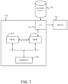
- The foregoing embodiments for joint PP-PS inversion tomography with co-depthing constraints have been described primarily in the context of methods or techniques. However, similar embodiments can be characterized as systems for processing the raw or partially processed seismic data that has been acquired by a system like that described above with respect to
Figure 3 (or other seismic acquisition systems). Such embodiments can take many forms such as thecomputing system 700 generally illustrated inFigure 7 ). Therein, one ormore processors 702 can receive inputseismic data 704 via input/output device(s) 706. The data can be processed to perform joint PP-PS inversion tomography with co-depthing constraint(s) as described above and temporarily stored in thememory device 708 prior to the other processing. When the seismic data processing is complete, one ormore images 710 of the subsurface associated with the seismic data can be generated either as a displayed image on a monitor, a hard copy on a printer or an electronic image stored to a removable memory device. - Methods in accordance with the foregoing embodiments can also be expressed in alternative fashions to those described above, e.g., with respect to
Figures 6(a)-6(d) . For example, as shown in the flowchart ofFigure 8 , a method for processing seismic data can include thestep 800 of jointly inverting primary wave (PP) and shear wave (PS) seismic data as part of a nonlinear tomography process which adheres to one or more co-depthing constraints. The disclosed embodiments describe, for example, systems and methods for performing joint PP-PS inversion tomography with co-depthing constraint(s) on seismic data. It should be understood that this description is not intended to limit the invention. Further, in the detailed description of the exemplary embodiments, numerous specific details are set forth in order to provide a comprehensive understanding of the invention. However, one skilled in the art would understand that various embodiments may be practiced without such specific details. - Although the features and elements of the present embodiments are described in the embodiments in particular combinations, each feature or element can be used alone without the other features and elements of the embodiments or in various combinations with or without other features and elements disclosed herein. The methods or flow charts provided in the present application may be implemented in a computer program, software, or firmware tangibly embodied in a computer-readable storage medium for execution by a general purpose computer or a processor.
- This written description uses examples of the subject matter disclosed to enable any person skilled in the art to practice the same, including making and using any devices or systems and performing any incorporated methods. The patentable scope of the subject matter is defined by the claims, and may include other examples that occur to those skilled in the art.
Claims (10)
- A computer-implemented method for processing seismic data characterized by comprising:
jointly inverting (800) primary wave (P) seismic data (PP data) and shear wave (S) seismic data (PS data) as part of a nonlinear tomography process which adheres to one or more co-depthing constraints, said jointly inverting step (800) comprising:kinematically re-migrating (620) the seismic data using PP and PS residual moveout (RMO) invariants and at least one of P or S horizon invariants;evaluating (622) a cost function which includes at least one term associated with the one or more co-depthing constraints;performing (624) a linear update of multi-layer velocity attributes using an output of the evaluating step which is constrained by co-depthing; andrepositioning (626) the at least one of the P or S horizons,wherein the one or more co-depthing constraints includes a reflector constraint which minimizes discrepancies between kinematically re-migrated seismic reflectors in PP and PS domains by adding an additional weighted term to the cost function. - The method of claim 1, wherein the one or more co-depthing constraints includes a volumetric constraint.
- The method of claim 2, wherein the volumetric constraint is based on a Vp/Vs ratio.
- The method of claim 3, wherein the Vp/Vs ratio is determined by:
Iteratively filtering PS and PP images associated with the seismic data until a misalignment criterion is satisfied. - The method of claim 1, wherein the steps of kinematically re-migrating (620), evaluating (622), performing (624) a linear update and repositioning (626) are iterated as part of an update loop until an exit criterion is satisfied.
- The method of claim 5, further comprising:outputting final pre-stack depth migrated seismic data when the exit criterion is satisfied; andgenerating an image of a subsurface using the final pre-stack depth migrated seismic data.
- A computer system for processing seismic data comprising:
an interface (706) configured to receive seismic data; said computer system being characterized by further comprising:
at least one processor (702) configured to jointly invert primary wave (P) seismic data (PP data) and shear wave (S) seismic data (PS data) as part of a nonlinear tomography process which adheres to one or more co-depthing constraints, by:kinematically re-migrating (620) the seismic data using PP and PS residual moveout (RMO) invariants and at least one of P or S horizon invariants;evaluating (622) a cost function which includes at least one term associated with the one or more co-depthing constraints;performing (624) a linear update of multi-layer velocity attributes using an output of the evaluating step which is constrained by co-depthing; andrepositioning (626) the at least one of the P or S horizons,wherein the one or more co-depthing constraints includes a reflector constraint which minimizes discrepancies between kinematically re-migrated seismic reflectors in PP and PS domains by adding an additional weighted term to the cost function. - The system of claim 7, wherein the one or more co-depthing constraints includes a volumetric constraint.
- The system of claim 8, wherein the volumetric constraint is based on a Vp/Vs ratio.
- The system of claim 9, wherein the Vp/Vs ratio is determined by the at least one processor being configured to iteratively filtering PS and PP images associated with the seismic data until a misalignment criterion is satisfied.
Applications Claiming Priority (2)
| Application Number | Priority Date | Filing Date | Title |
|---|---|---|---|
| US201461926449P | 2014-01-13 | 2014-01-13 | |
| PCT/IB2015/000236 WO2015104640A2 (en) | 2014-01-13 | 2015-01-13 | Velocity model building for seismic data processing using pp-ps tomography with co-depthing constraint |
Publications (2)
| Publication Number | Publication Date |
|---|---|
| EP3094992A2 EP3094992A2 (en) | 2016-11-23 |
| EP3094992B1 true EP3094992B1 (en) | 2022-03-16 |
Family
ID=52706203
Family Applications (1)
| Application Number | Title | Priority Date | Filing Date |
|---|---|---|---|
| EP15711564.3A Active EP3094992B1 (en) | 2014-01-13 | 2015-01-13 | Velocity model building for seismic data processing using pp-ps tomography with co-depthing constraint |
Country Status (3)
| Country | Link |
|---|---|
| US (1) | US11614554B2 (en) |
| EP (1) | EP3094992B1 (en) |
| WO (1) | WO2015104640A2 (en) |
Families Citing this family (13)
| Publication number | Priority date | Publication date | Assignee | Title |
|---|---|---|---|---|
| EP3183599B1 (en) * | 2014-08-19 | 2022-07-13 | CGG Services SAS | Joint inversion of compressional and shear seismic data in native time domains |
| WO2017142544A1 (en) * | 2016-02-19 | 2017-08-24 | Landmark Graphic Corporation | Seismic well ties using blocking schemes |
| US10739481B2 (en) * | 2016-03-30 | 2020-08-11 | Exxonmobil Upstream Research Company | 2D multiline seismic reflection tomography with seismic-tie constraint |
| US10261203B2 (en) * | 2016-06-24 | 2019-04-16 | Pgs Geophysical As | Migrating a horizontal component of a wavefield |
| US10620331B2 (en) * | 2016-06-28 | 2020-04-14 | Exxonmobil Upstream Research Company | Reverse time migration in anisotropic media with stable attenuation compensation |
| US10620341B2 (en) | 2016-12-19 | 2020-04-14 | Chevron U.S.A. Inc. | System and method for modifying an earth model |
| CN109581496B (en) * | 2018-10-29 | 2020-09-08 | 中国石油天然气集团有限公司 | Bidirectional construction dip angle constraint method and device in tomography inversion |
| CN109581497B (en) * | 2018-10-29 | 2020-09-04 | 中国石油天然气集团有限公司 | Bidirectional construction dip angle constraint method and device in tomography inversion |
| US11119231B2 (en) * | 2020-01-15 | 2021-09-14 | Shell Oil Company | Method for structure model building |
| US20220137245A1 (en) * | 2020-11-03 | 2022-05-05 | Saudi Arabian Oil Company | Systems and methods for seismic well tie domain conversion and neural network modeling |
| US11933930B2 (en) * | 2021-02-25 | 2024-03-19 | Saudi Arabian Oil Company | Automatic image registration of multicomponent seismic data |
| CN113031070B (en) * | 2021-03-19 | 2022-06-28 | 大庆油田有限责任公司 | Method for making depth domain synthetic seismic record |
| CN115343763B (en) * | 2021-05-14 | 2023-08-01 | 中国石油化工股份有限公司 | Ant body attribute dip angle correction method based on seismic event zero-phase discrimination |
Family Cites Families (10)
| Publication number | Priority date | Publication date | Assignee | Title |
|---|---|---|---|---|
| FR2821677B1 (en) | 2001-03-05 | 2004-04-30 | Geophysique Cie Gle | IMPROVEMENTS TO TOMOGRAPHIC INVERSION PROCESSES OF POINTED EVENTS ON MIGREE SEISMIC DATA |
| US6611764B2 (en) | 2001-06-08 | 2003-08-26 | Pgs Americas, Inc. | Method and system for determining P-wave and S-wave velocities from multi-component seismic data by joint velocity inversion processing |
| US7082368B2 (en) | 2004-06-04 | 2006-07-25 | Schlumberger Technology Corporation | Seismic event correlation and Vp-Vs estimation |
| US7660202B2 (en) | 2005-10-11 | 2010-02-09 | Westerngeco L.L.C. | PP/PS event matching (registration) |
| US8379482B1 (en) | 2009-01-13 | 2013-02-19 | Exxonmobil Upstream Research Company | Using seismic attributes for data alignment and seismic inversion in joint PP/PS seismic analysis |
| GB2490051B (en) * | 2009-12-07 | 2015-04-01 | Geco Technology Bv | Simultaneous joint inversion of surface wave and refraction data |
| US10977396B2 (en) * | 2012-01-13 | 2021-04-13 | Schlumberger Technology Corporation | Determining an elastic model for a geologic region |
| CN102914796B (en) | 2012-08-21 | 2013-11-13 | 北京多分量地震技术研究院 | Control method for acquiring offset speeds of longitudinal and transverse waves based on Gaussian beam |
| EP2755055B1 (en) | 2013-01-11 | 2022-03-02 | CGG Services SAS | Dip based tomography for estimating depth velocity models by inverting pre-stack dip information present in migrated seismic data |
| CN103472482B (en) | 2013-09-03 | 2016-07-06 | 中国石油天然气集团公司 | Multi-wave seismic data time domain matching process and system based on gene order system |
-
2015
- 2015-01-13 WO PCT/IB2015/000236 patent/WO2015104640A2/en active Application Filing
- 2015-01-13 EP EP15711564.3A patent/EP3094992B1/en active Active
- 2015-01-13 US US15/111,011 patent/US11614554B2/en active Active
Non-Patent Citations (1)
| Title |
|---|
| PATRICE GUILLAUME ET AL: "Multi-layer non-linear slope tomography", 75TH EAGE CONFERENCE & EXHIBITION INCORPORATING SPE EUROPEC 2013, 10 June 2013 (2013-06-10), XP055284288 * |
Also Published As
| Publication number | Publication date |
|---|---|
| EP3094992A2 (en) | 2016-11-23 |
| US20160341835A1 (en) | 2016-11-24 |
| WO2015104640A2 (en) | 2015-07-16 |
| WO2015104640A3 (en) | 2016-01-28 |
| US11614554B2 (en) | 2023-03-28 |
Similar Documents
| Publication | Publication Date | Title |
|---|---|---|
| EP3094992B1 (en) | Velocity model building for seismic data processing using pp-ps tomography with co-depthing constraint | |
| Warner et al. | Anisotropic 3D full-waveform inversion | |
| Martin et al. | Marmousi-2: An updated model for the investigation of AVO in structurally complex areas | |
| US8352190B2 (en) | Method for analyzing multiple geophysical data sets | |
| US6826484B2 (en) | 3D prestack time migration method | |
| US8203907B2 (en) | Updating velocity models using migration velocity scans | |
| EP1563324B1 (en) | Seismic analysis using post-imaging seismic anisotropy corrections | |
| CA2777980C (en) | Method and system for seismic imaging and earth modeling using beam tomography | |
| US6839658B2 (en) | Seismic processing with general non-hyperbolic travel-time corrections | |
| US10267937B2 (en) | Generating subterranean imaging data based on vertical seismic profile data and ocean bottom sensor data | |
| Kamei et al. | On acoustic waveform tomography of wide-angle OBS data—strategies for pre-conditioning and inversion | |
| Deng et al. | Viscoelastic true-amplitude prestack reverse-time depth migration | |
| Wang et al. | Inversion of seismic refraction and reflection data for building long-wavelength velocity models | |
| US20090257308A1 (en) | Migration velocity analysis methods | |
| EP3067718B1 (en) | Boundary layer tomography method and device | |
| EP3529640A1 (en) | Generating subterranean imaging data based on vertical seismic profile data and ocean bottom sensor data | |
| Cheng et al. | Azimuth-preserved local angle-domain prestack time migration in isotropic, vertical transversely isotropic and azimuthally anisotropic media | |
| Rabben et al. | AVA inversion of the top Utsira Sand reflection at the Sleipner field | |
| Jones | Estimating subsurface parameter fields for seismic migration: velocity model building | |
| Guo et al. | Becoming effective velocity-model builders and depth imagers, Part 2—The basics of velocity-model building, examples and discussions | |
| Yang et al. | Image-domain waveform tomography with two-way wave-equation | |
| Cai et al. | Joint migration velocity analysis of PP-and PS-waves for VTI media | |
| Graham | Interpretation-Based Full Waveform Inversion | |
| Duan | Elastic wavefield migration and tomography | |
| Wang et al. | Converted-wave reflection traveltime inversion with free-surface multiples for ocean-bottom-node data |
Legal Events
| Date | Code | Title | Description |
|---|---|---|---|
| PUAI | Public reference made under article 153(3) epc to a published international application that has entered the european phase |
Free format text: ORIGINAL CODE: 0009012 |
|
| 17P | Request for examination filed |
Effective date: 20160706 |
|
| AK | Designated contracting states |
Kind code of ref document: A2 Designated state(s): AL AT BE BG CH CY CZ DE DK EE ES FI FR GB GR HR HU IE IS IT LI LT LU LV MC MK MT NL NO PL PT RO RS SE SI SK SM TR |
|
| AX | Request for extension of the european patent |
Extension state: BA ME |
|
| DAX | Request for extension of the european patent (deleted) | ||
| STAA | Information on the status of an ep patent application or granted ep patent |
Free format text: STATUS: EXAMINATION IS IN PROGRESS |
|
| 17Q | First examination report despatched |
Effective date: 20171207 |
|
| STAA | Information on the status of an ep patent application or granted ep patent |
Free format text: STATUS: EXAMINATION IS IN PROGRESS |
|
| GRAP | Despatch of communication of intention to grant a patent |
Free format text: ORIGINAL CODE: EPIDOSNIGR1 |
|
| STAA | Information on the status of an ep patent application or granted ep patent |
Free format text: STATUS: GRANT OF PATENT IS INTENDED |
|
| GRAJ | Information related to disapproval of communication of intention to grant by the applicant or resumption of examination proceedings by the epo deleted |
Free format text: ORIGINAL CODE: EPIDOSDIGR1 |
|
| GRAP | Despatch of communication of intention to grant a patent |
Free format text: ORIGINAL CODE: EPIDOSNIGR1 |
|
| GRAJ | Information related to disapproval of communication of intention to grant by the applicant or resumption of examination proceedings by the epo deleted |
Free format text: ORIGINAL CODE: EPIDOSDIGR1 |
|
| STAA | Information on the status of an ep patent application or granted ep patent |
Free format text: STATUS: EXAMINATION IS IN PROGRESS |
|
| INTG | Intention to grant announced |
Effective date: 20211011 |
|
| INTG | Intention to grant announced |
Effective date: 20211027 |
|
| GRAP | Despatch of communication of intention to grant a patent |
Free format text: ORIGINAL CODE: EPIDOSNIGR1 |
|
| STAA | Information on the status of an ep patent application or granted ep patent |
Free format text: STATUS: GRANT OF PATENT IS INTENDED |
|
| INTC | Intention to grant announced (deleted) | ||
| INTG | Intention to grant announced |
Effective date: 20211203 |
|
| GRAS | Grant fee paid |
Free format text: ORIGINAL CODE: EPIDOSNIGR3 |
|
| GRAA | (expected) grant |
Free format text: ORIGINAL CODE: 0009210 |
|
| STAA | Information on the status of an ep patent application or granted ep patent |
Free format text: STATUS: THE PATENT HAS BEEN GRANTED |
|
| RAP3 | Party data changed (applicant data changed or rights of an application transferred) |
Owner name: CGG SERVICES SAS |
|
| AK | Designated contracting states |
Kind code of ref document: B1 Designated state(s): AL AT BE BG CH CY CZ DE DK EE ES FI FR GB GR HR HU IE IS IT LI LT LU LV MC MK MT NL NO PL PT RO RS SE SI SK SM TR |
|
| REG | Reference to a national code |
Ref country code: GB Ref legal event code: FG4D |
|
| REG | Reference to a national code |
Ref country code: CH Ref legal event code: EP Ref country code: DE Ref legal event code: R096 Ref document number: 602015077547 Country of ref document: DE |
|
| REG | Reference to a national code |
Ref country code: IE Ref legal event code: FG4D |
|
| REG | Reference to a national code |
Ref country code: AT Ref legal event code: REF Ref document number: 1476294 Country of ref document: AT Kind code of ref document: T Effective date: 20220415 |
|
| REG | Reference to a national code |
Ref country code: NO Ref legal event code: T2 Effective date: 20220316 |
|
| REG | Reference to a national code |
Ref country code: LT Ref legal event code: MG9D |
|
| REG | Reference to a national code |
Ref country code: NL Ref legal event code: MP Effective date: 20220316 |
|
| PG25 | Lapsed in a contracting state [announced via postgrant information from national office to epo] |
Ref country code: SE Free format text: LAPSE BECAUSE OF FAILURE TO SUBMIT A TRANSLATION OF THE DESCRIPTION OR TO PAY THE FEE WITHIN THE PRESCRIBED TIME-LIMIT Effective date: 20220316 Ref country code: RS Free format text: LAPSE BECAUSE OF FAILURE TO SUBMIT A TRANSLATION OF THE DESCRIPTION OR TO PAY THE FEE WITHIN THE PRESCRIBED TIME-LIMIT Effective date: 20220316 Ref country code: LT Free format text: LAPSE BECAUSE OF FAILURE TO SUBMIT A TRANSLATION OF THE DESCRIPTION OR TO PAY THE FEE WITHIN THE PRESCRIBED TIME-LIMIT Effective date: 20220316 Ref country code: HR Free format text: LAPSE BECAUSE OF FAILURE TO SUBMIT A TRANSLATION OF THE DESCRIPTION OR TO PAY THE FEE WITHIN THE PRESCRIBED TIME-LIMIT Effective date: 20220316 Ref country code: BG Free format text: LAPSE BECAUSE OF FAILURE TO SUBMIT A TRANSLATION OF THE DESCRIPTION OR TO PAY THE FEE WITHIN THE PRESCRIBED TIME-LIMIT Effective date: 20220616 |
|
| REG | Reference to a national code |
Ref country code: AT Ref legal event code: MK05 Ref document number: 1476294 Country of ref document: AT Kind code of ref document: T Effective date: 20220316 |
|
| PG25 | Lapsed in a contracting state [announced via postgrant information from national office to epo] |
Ref country code: LV Free format text: LAPSE BECAUSE OF FAILURE TO SUBMIT A TRANSLATION OF THE DESCRIPTION OR TO PAY THE FEE WITHIN THE PRESCRIBED TIME-LIMIT Effective date: 20220316 Ref country code: GR Free format text: LAPSE BECAUSE OF FAILURE TO SUBMIT A TRANSLATION OF THE DESCRIPTION OR TO PAY THE FEE WITHIN THE PRESCRIBED TIME-LIMIT Effective date: 20220617 Ref country code: FI Free format text: LAPSE BECAUSE OF FAILURE TO SUBMIT A TRANSLATION OF THE DESCRIPTION OR TO PAY THE FEE WITHIN THE PRESCRIBED TIME-LIMIT Effective date: 20220316 |
|
| PG25 | Lapsed in a contracting state [announced via postgrant information from national office to epo] |
Ref country code: NL Free format text: LAPSE BECAUSE OF FAILURE TO SUBMIT A TRANSLATION OF THE DESCRIPTION OR TO PAY THE FEE WITHIN THE PRESCRIBED TIME-LIMIT Effective date: 20220316 |
|
| PG25 | Lapsed in a contracting state [announced via postgrant information from national office to epo] |
Ref country code: SM Free format text: LAPSE BECAUSE OF FAILURE TO SUBMIT A TRANSLATION OF THE DESCRIPTION OR TO PAY THE FEE WITHIN THE PRESCRIBED TIME-LIMIT Effective date: 20220316 Ref country code: SK Free format text: LAPSE BECAUSE OF FAILURE TO SUBMIT A TRANSLATION OF THE DESCRIPTION OR TO PAY THE FEE WITHIN THE PRESCRIBED TIME-LIMIT Effective date: 20220316 Ref country code: RO Free format text: LAPSE BECAUSE OF FAILURE TO SUBMIT A TRANSLATION OF THE DESCRIPTION OR TO PAY THE FEE WITHIN THE PRESCRIBED TIME-LIMIT Effective date: 20220316 Ref country code: PT Free format text: LAPSE BECAUSE OF FAILURE TO SUBMIT A TRANSLATION OF THE DESCRIPTION OR TO PAY THE FEE WITHIN THE PRESCRIBED TIME-LIMIT Effective date: 20220718 Ref country code: ES Free format text: LAPSE BECAUSE OF FAILURE TO SUBMIT A TRANSLATION OF THE DESCRIPTION OR TO PAY THE FEE WITHIN THE PRESCRIBED TIME-LIMIT Effective date: 20220316 Ref country code: EE Free format text: LAPSE BECAUSE OF FAILURE TO SUBMIT A TRANSLATION OF THE DESCRIPTION OR TO PAY THE FEE WITHIN THE PRESCRIBED TIME-LIMIT Effective date: 20220316 Ref country code: CZ Free format text: LAPSE BECAUSE OF FAILURE TO SUBMIT A TRANSLATION OF THE DESCRIPTION OR TO PAY THE FEE WITHIN THE PRESCRIBED TIME-LIMIT Effective date: 20220316 Ref country code: AT Free format text: LAPSE BECAUSE OF FAILURE TO SUBMIT A TRANSLATION OF THE DESCRIPTION OR TO PAY THE FEE WITHIN THE PRESCRIBED TIME-LIMIT Effective date: 20220316 |
|
| PG25 | Lapsed in a contracting state [announced via postgrant information from national office to epo] |
Ref country code: PL Free format text: LAPSE BECAUSE OF FAILURE TO SUBMIT A TRANSLATION OF THE DESCRIPTION OR TO PAY THE FEE WITHIN THE PRESCRIBED TIME-LIMIT Effective date: 20220316 Ref country code: IS Free format text: LAPSE BECAUSE OF FAILURE TO SUBMIT A TRANSLATION OF THE DESCRIPTION OR TO PAY THE FEE WITHIN THE PRESCRIBED TIME-LIMIT Effective date: 20220716 Ref country code: AL Free format text: LAPSE BECAUSE OF FAILURE TO SUBMIT A TRANSLATION OF THE DESCRIPTION OR TO PAY THE FEE WITHIN THE PRESCRIBED TIME-LIMIT Effective date: 20220316 |
|
| REG | Reference to a national code |
Ref country code: DE Ref legal event code: R097 Ref document number: 602015077547 Country of ref document: DE |
|
| PLBE | No opposition filed within time limit |
Free format text: ORIGINAL CODE: 0009261 |
|
| STAA | Information on the status of an ep patent application or granted ep patent |
Free format text: STATUS: NO OPPOSITION FILED WITHIN TIME LIMIT |
|
| PG25 | Lapsed in a contracting state [announced via postgrant information from national office to epo] |
Ref country code: DK Free format text: LAPSE BECAUSE OF FAILURE TO SUBMIT A TRANSLATION OF THE DESCRIPTION OR TO PAY THE FEE WITHIN THE PRESCRIBED TIME-LIMIT Effective date: 20220316 |
|
| 26N | No opposition filed |
Effective date: 20221219 |
|
| PG25 | Lapsed in a contracting state [announced via postgrant information from national office to epo] |
Ref country code: SI Free format text: LAPSE BECAUSE OF FAILURE TO SUBMIT A TRANSLATION OF THE DESCRIPTION OR TO PAY THE FEE WITHIN THE PRESCRIBED TIME-LIMIT Effective date: 20220316 |
|
| PGFP | Annual fee paid to national office [announced via postgrant information from national office to epo] |
Ref country code: NO Payment date: 20230123 Year of fee payment: 9 |
|
| PGFP | Annual fee paid to national office [announced via postgrant information from national office to epo] |
Ref country code: GB Payment date: 20230119 Year of fee payment: 9 |
|
| P01 | Opt-out of the competence of the unified patent court (upc) registered |
Effective date: 20230530 |
|
| PG25 | Lapsed in a contracting state [announced via postgrant information from national office to epo] |
Ref country code: IT Free format text: LAPSE BECAUSE OF FAILURE TO SUBMIT A TRANSLATION OF THE DESCRIPTION OR TO PAY THE FEE WITHIN THE PRESCRIBED TIME-LIMIT Effective date: 20220316 |
|
| REG | Reference to a national code |
Ref country code: DE Ref legal event code: R119 Ref document number: 602015077547 Country of ref document: DE |
|
| REG | Reference to a national code |
Ref country code: CH Ref legal event code: PL |
|
| PG25 | Lapsed in a contracting state [announced via postgrant information from national office to epo] |
Ref country code: LU Free format text: LAPSE BECAUSE OF NON-PAYMENT OF DUE FEES Effective date: 20230113 |
|
| REG | Reference to a national code |
Ref country code: BE Ref legal event code: MM Effective date: 20230131 |
|
| PG25 | Lapsed in a contracting state [announced via postgrant information from national office to epo] |
Ref country code: LI Free format text: LAPSE BECAUSE OF NON-PAYMENT OF DUE FEES Effective date: 20230131 Ref country code: DE Free format text: LAPSE BECAUSE OF NON-PAYMENT OF DUE FEES Effective date: 20230801 Ref country code: CH Free format text: LAPSE BECAUSE OF NON-PAYMENT OF DUE FEES Effective date: 20230131 |
|
| PG25 | Lapsed in a contracting state [announced via postgrant information from national office to epo] |
Ref country code: FR Free format text: LAPSE BECAUSE OF NON-PAYMENT OF DUE FEES Effective date: 20230131 Ref country code: BE Free format text: LAPSE BECAUSE OF NON-PAYMENT OF DUE FEES Effective date: 20230131 |
|
| PG25 | Lapsed in a contracting state [announced via postgrant information from national office to epo] |
Ref country code: IE Free format text: LAPSE BECAUSE OF NON-PAYMENT OF DUE FEES Effective date: 20230113 |