EP3772629A1 - Heat dissipating fin with thermosiphon - Google Patents
Heat dissipating fin with thermosiphon Download PDFInfo
- Publication number
- EP3772629A1 EP3772629A1 EP20161165.4A EP20161165A EP3772629A1 EP 3772629 A1 EP3772629 A1 EP 3772629A1 EP 20161165 A EP20161165 A EP 20161165A EP 3772629 A1 EP3772629 A1 EP 3772629A1
- Authority
- EP
- European Patent Office
- Prior art keywords
- tube
- fin
- edge
- heat transfer
- transfer device
- Prior art date
- Legal status (The legal status is an assumption and is not a legal conclusion. Google has not performed a legal analysis and makes no representation as to the accuracy of the status listed.)
- Granted
Links
Images


Classifications
-
- F—MECHANICAL ENGINEERING; LIGHTING; HEATING; WEAPONS; BLASTING
- F28—HEAT EXCHANGE IN GENERAL
- F28F—DETAILS OF HEAT-EXCHANGE AND HEAT-TRANSFER APPARATUS, OF GENERAL APPLICATION
- F28F13/00—Arrangements for modifying heat-transfer, e.g. increasing, decreasing
- F28F13/06—Arrangements for modifying heat-transfer, e.g. increasing, decreasing by affecting the pattern of flow of the heat-exchange media
-
- F—MECHANICAL ENGINEERING; LIGHTING; HEATING; WEAPONS; BLASTING
- F28—HEAT EXCHANGE IN GENERAL
- F28D—HEAT-EXCHANGE APPARATUS, NOT PROVIDED FOR IN ANOTHER SUBCLASS, IN WHICH THE HEAT-EXCHANGE MEDIA DO NOT COME INTO DIRECT CONTACT
- F28D15/00—Heat-exchange apparatus with the intermediate heat-transfer medium in closed tubes passing into or through the conduit walls ; Heat-exchange apparatus employing intermediate heat-transfer medium or bodies
- F28D15/02—Heat-exchange apparatus with the intermediate heat-transfer medium in closed tubes passing into or through the conduit walls ; Heat-exchange apparatus employing intermediate heat-transfer medium or bodies in which the medium condenses and evaporates, e.g. heat pipes
- F28D15/0266—Heat-exchange apparatus with the intermediate heat-transfer medium in closed tubes passing into or through the conduit walls ; Heat-exchange apparatus employing intermediate heat-transfer medium or bodies in which the medium condenses and evaporates, e.g. heat pipes with separate evaporating and condensing chambers connected by at least one conduit; Loop-type heat pipes; with multiple or common evaporating or condensing chambers
-
- F—MECHANICAL ENGINEERING; LIGHTING; HEATING; WEAPONS; BLASTING
- F28—HEAT EXCHANGE IN GENERAL
- F28D—HEAT-EXCHANGE APPARATUS, NOT PROVIDED FOR IN ANOTHER SUBCLASS, IN WHICH THE HEAT-EXCHANGE MEDIA DO NOT COME INTO DIRECT CONTACT
- F28D15/00—Heat-exchange apparatus with the intermediate heat-transfer medium in closed tubes passing into or through the conduit walls ; Heat-exchange apparatus employing intermediate heat-transfer medium or bodies
- F28D15/02—Heat-exchange apparatus with the intermediate heat-transfer medium in closed tubes passing into or through the conduit walls ; Heat-exchange apparatus employing intermediate heat-transfer medium or bodies in which the medium condenses and evaporates, e.g. heat pipes
- F28D15/025—Heat-exchange apparatus with the intermediate heat-transfer medium in closed tubes passing into or through the conduit walls ; Heat-exchange apparatus employing intermediate heat-transfer medium or bodies in which the medium condenses and evaporates, e.g. heat pipes having non-capillary condensate return means
-
- F—MECHANICAL ENGINEERING; LIGHTING; HEATING; WEAPONS; BLASTING
- F28—HEAT EXCHANGE IN GENERAL
- F28D—HEAT-EXCHANGE APPARATUS, NOT PROVIDED FOR IN ANOTHER SUBCLASS, IN WHICH THE HEAT-EXCHANGE MEDIA DO NOT COME INTO DIRECT CONTACT
- F28D15/00—Heat-exchange apparatus with the intermediate heat-transfer medium in closed tubes passing into or through the conduit walls ; Heat-exchange apparatus employing intermediate heat-transfer medium or bodies
- F28D15/02—Heat-exchange apparatus with the intermediate heat-transfer medium in closed tubes passing into or through the conduit walls ; Heat-exchange apparatus employing intermediate heat-transfer medium or bodies in which the medium condenses and evaporates, e.g. heat pipes
- F28D15/0283—Means for filling or sealing heat pipes
-
- F—MECHANICAL ENGINEERING; LIGHTING; HEATING; WEAPONS; BLASTING
- F28—HEAT EXCHANGE IN GENERAL
- F28F—DETAILS OF HEAT-EXCHANGE AND HEAT-TRANSFER APPARATUS, OF GENERAL APPLICATION
- F28F1/00—Tubular elements; Assemblies of tubular elements
- F28F1/10—Tubular elements and assemblies thereof with means for increasing heat-transfer area, e.g. with fins, with projections, with recesses
- F28F1/12—Tubular elements and assemblies thereof with means for increasing heat-transfer area, e.g. with fins, with projections, with recesses the means being only outside the tubular element
- F28F1/14—Tubular elements and assemblies thereof with means for increasing heat-transfer area, e.g. with fins, with projections, with recesses the means being only outside the tubular element and extending longitudinally
- F28F1/20—Tubular elements and assemblies thereof with means for increasing heat-transfer area, e.g. with fins, with projections, with recesses the means being only outside the tubular element and extending longitudinally the means being attachable to the element
-
- F—MECHANICAL ENGINEERING; LIGHTING; HEATING; WEAPONS; BLASTING
- F28—HEAT EXCHANGE IN GENERAL
- F28F—DETAILS OF HEAT-EXCHANGE AND HEAT-TRANSFER APPARATUS, OF GENERAL APPLICATION
- F28F3/00—Plate-like or laminated elements; Assemblies of plate-like or laminated elements
- F28F3/02—Elements or assemblies thereof with means for increasing heat-transfer area, e.g. with fins, with recesses, with corrugations
-
- H—ELECTRICITY
- H10—SEMICONDUCTOR DEVICES; ELECTRIC SOLID-STATE DEVICES NOT OTHERWISE PROVIDED FOR
- H10W—GENERIC PACKAGES, INTERCONNECTIONS, CONNECTORS OR OTHER CONSTRUCTIONAL DETAILS OF DEVICES COVERED BY CLASS H10
- H10W40/00—Arrangements for thermal protection or thermal control
- H10W40/20—Arrangements for cooling
- H10W40/22—Arrangements for cooling characterised by their shape, e.g. having conical or cylindrical projections
- H10W40/226—Arrangements for cooling characterised by their shape, e.g. having conical or cylindrical projections characterised by projecting parts, e.g. fins to increase surface area
-
- H—ELECTRICITY
- H10—SEMICONDUCTOR DEVICES; ELECTRIC SOLID-STATE DEVICES NOT OTHERWISE PROVIDED FOR
- H10W—GENERIC PACKAGES, INTERCONNECTIONS, CONNECTORS OR OTHER CONSTRUCTIONAL DETAILS OF DEVICES COVERED BY CLASS H10
- H10W40/00—Arrangements for thermal protection or thermal control
- H10W40/70—Fillings or auxiliary members in containers or in encapsulations for thermal protection or control
- H10W40/73—Fillings or auxiliary members in containers or in encapsulations for thermal protection or control for cooling by change of state
-
- F—MECHANICAL ENGINEERING; LIGHTING; HEATING; WEAPONS; BLASTING
- F28—HEAT EXCHANGE IN GENERAL
- F28D—HEAT-EXCHANGE APPARATUS, NOT PROVIDED FOR IN ANOTHER SUBCLASS, IN WHICH THE HEAT-EXCHANGE MEDIA DO NOT COME INTO DIRECT CONTACT
- F28D15/00—Heat-exchange apparatus with the intermediate heat-transfer medium in closed tubes passing into or through the conduit walls ; Heat-exchange apparatus employing intermediate heat-transfer medium or bodies
- F28D15/02—Heat-exchange apparatus with the intermediate heat-transfer medium in closed tubes passing into or through the conduit walls ; Heat-exchange apparatus employing intermediate heat-transfer medium or bodies in which the medium condenses and evaporates, e.g. heat pipes
- F28D2015/0225—Microheat pipes
Definitions
- This invention relates generally to heat transfer fins or other devices that employ a two-phase thermosiphon.
- thermosiphon devices are widely used for cooling systems, such as integrated circuits and other computer circuitry.
- U.S. Patent Publication 2013/0104592 , US Patent 6,097,597 and US Patent 8,913,386 disclose thermosiphon devices for cooling electronic components or other heat generating elements.
- One aspect of the invention is a heat transfer device/assembly, preferably a heat sink, that comprises at least one planar fin having first and second opposed faces and a heat receiving portion at an edge of the planar fin and at least one thermosiphon component physically and thermally connected to the at least one planar fin and adapted to transfer heat from the heat receiving portion to other areas of the fin.
- the heat transfer device here and further described below thus embraces various configurations, for example, where only one or both of the first and second opposed faces has a thermosiphon component connected/attached thereto. Furthermore, several thermosiphon components per first and second opposed face are conceivable.
- the planar fin optionally contains or is made of an aluminum material.
- the opposed first and second faces are herein preferably meant to be the major front and back surfaces of the planar fin, i.e., the faces with the largest surface area.
- the heat receiving portion herein is meant to be a section/region of the planar fin close/closest to a heat source via which heat is taken up from the heat source and conducted into the planar fin for dissipation.
- the heat transfer device optionally comprises a plurality of fins with thermosiphon components spatially arranged to form a vertical or horizontal array and further optionally with an air gap or space between said individual fins with thermosiphon devices.
- one of the above planar fins with the at least one thermosiphon component connected/attached thereto forms an individual sub-component of the array, in which array several of said sub-components are purposefully arranged and combined to form a larger heat transfer device.
- array several of said sub-components are purposefully arranged and combined to form a larger heat transfer device.
- several of such sub-components can be stacked vertically or arranged in a row horizontally to form a subcomponent array.
- air gaps or spaces are formed between the arrayed sub-components.
- a further aspect of the invention that can be seen to stand-alone or optionally to be an advancement of the above aspect provides a heat transfer device that includes a planar fin having first and second opposed faces, preferably the major surfaces of the planar fin, and a heat receiving portion at an edge of the planar fin. At least one tube forming a continuous, closed loop and optionally containing a working fluid may be physically and thermally connected to the first face of the planar fin so that heat may be transferred between the fin and tube.
- the at least one tube and working fluid may be adapted to operate as a two-phase thermosiphon in which working fluid is evaporated in an evaporation portion of the at least one tube adjacent the heat receiving portion of the planar fin, and working fluid vapor flows in the at least one tube away from the evaporation portion for condensing.
- the at least one tube and working fluid may aid in transferring heat from relatively hotter areas of the fin to relatively cooler areas, thereby improving efficiency of the fin.
- This arrangement can be particularly useful with fins made of relatively thin and/or relatively lower thermal conductance, such as aluminum sheet materials.
- the at least one tube may be arranged to equalize a temperature of the planar fin at the heat receiving portion with temperatures of the planar fin in areas away from the heat receiving portion.
- Part of the present invention is a heat transfer device in which the continuous, closed loop formed by the at least one tube contains a suitable working fluid but also where no working fluid is contained yet that may be added later when using the heat transfer device.
- the at least one tube is adapted for flow of working fluid in only a single direction along the continuous, closed loop during operation, while in other embodiments the at least one tube is adapted for counterflow of working fluid in the continuous, closed loop during operation.
- the at least one tube includes a multiport tube having multiple flow channels. This may allow use of a tube that has a relatively thin wall thickness, but can withstand relatively high internal pressures.
- the multiport tube has a linear array of the flow channels, and the multiport tube may be attached to the first face of the planar fin such that each flow channel in the linear array is adjacent the first face.
- a manifold portion may fluidly connect the multiple flow channels in two portions of the tube with each other, e.g., the manifold portion may physically connect ends of the tube together as well as provide a manifold chamber that permits fluid communication between flow channels.
- the manifold portion is located on the continuous, closed loop where the working fluid is mostly in a liquid state, which may allow the flow channels to maintain about the same amount of liquid phase working fluid.
- the manifold portion is located on the continuous, closed loop where the working fluid is mostly in a vapor state, which may allow for pressure equalization between flow channels.
- the manifold portion may be defined by a coupling that joins ends of the at least one tube to each other, e.g., the coupling may be formed by receiving a first end of the multiport tube into a second end of the multiport tube.
- Such configuration is basically a male-female coupling type, but other types, for example, a sleeve-type coupling or a butt joint are also embraced.
- the planar fin includes an opening in which the manifold portion is positioned, which may allow the manifold portion to be at least partially recessed relative to the face of the fin to which the tube is attached.
- the planar fin may include one or more openings to receive other components, such as electrical wiring or fasteners, and/or to permit air or other fluid flow through the opening, e.g., from a first face of the fin to the second face.
- a coupling may include a sealable port or fill port or tubular port arranged to allow evacuation of the continuous, closed loop of the tube and/or providing of working fluid to the loop.
- the sealable port or fill port or tubular port may be secured to an opening of the coupling and have a channel that provides fluid communication between the sealable port or fill port or tubular port and an interior space of the coupling.
- the sealable port or fill port or tubular port may provide a stop for tube ends received into the coupling, and/or a leg of the sealable port or fill port or tubular port that defines a channel may limit an extent to which the sealable port or fill port or tubular port is extended into the coupling.
- the sealable port or fill port or tubular port may include a stop to limit an extent to which the sealable port or fill port or tubular port can be extended into or through the coupling.
- the planar fin has a rectangular shape with a first edge opposite a second edge and a third edge opposite a fourth edge.
- the heat receiving portion of the fin may be at the first edge of the rectangular shape, and the at least one tube may have a first portion that extends outwardly along the first edge toward the third and fourth edges, third and fourth portions that respectively extend along the third and fourth edges toward the second edge, and a second portion extends inwardly along the second edge.
- the first portion of the tube at least in part defines the evaporation portion
- the at least one tube is arranged so that working fluid vapor flows in the at least one tube from the evaporation portion to the third and fourth portions, and flows from the third and fourth portions to the second portion.
- the at least one tube may be arranged such that condensed working fluid liquid flows in the at least one tube from the second portion to the third and fourth portions, and from the third and fourth portions to the first portion.
- the continuous, closed loop formed by the at least one tube has an oval-like overall shape resembling an athletic racetrack layout with two parallel linear sections connected by two curved sections.
- one of the linear sections is situated in and connected to the heat receiving portion of the planar fin and the other linear section is situated away from or opposite the heat receiving portion such that heat from the heat receiving portion is transported to cooler regions of the planar fin.
- several of said racetrack loops for example, of different sizes are combined on the respective faces of the planar fin, preferably with a higher number/density of linear sections arranged in the heat receiving portion and a lower number/density of linear sections in the away portion of the planar fin or vice versa. This concept can also be applied to all the other tube/loop layouts described herein.
- the heat transfer device may include a base that supports the planar fin and the at least one tube and transfers heat to the planar fin and the at least one tube.
- the base may be in thermal communication with a heat source, such as an integrated circuit or other electronic device, and transfer heat from the heat source to the fin and tube.
- the base includes a groove that receives at least a part of the first edge of the planar fin and optionally the first portion of the at least one tube, e.g., so heat can be transferred directly from the base to the fin and tube.
- a fin may have one or more tubes attached to it, either on the first face or second face or both faces, e.g., a first tube may be bonded to the first face of the planar fin, and a second tube may be bonded to the second face of the planar fin.
- the second portion of a tube has parts that extend inwardly from the third and fourth portions along the second edge of the fin at an angle relative to the second edge such that a central part of the second portion is located closer to the second edge than outer parts of the second portion. This may aid in gravity assisted flow of liquid in the second portion toward the third and fourth portions of the tube.
- the second portion has parts that extend inwardly from the third and fourth portions along the second edge at an angle relative to the second edge such that a part of the second portion nearest the third portion is located closer to the second edge than a part of the second portion nearest the fourth portion. This may aid in gravity assisted flow of liquid in the second portion toward the fourth portion.
- the third and fourth portions may each have twist bends, e.g., a pair of 90/90 degree twist bends or 180/90 degree twist bends, and the third and fourth portions may be located away from the plane of the first face.
- twist bends may allow for various positioning and orientation of the third and fourth portions relative to the fin.
- an intermediate part of the third and fourth portions between twist bends may be arranged in a plane parallel to the plane of the first face, e.g., to help reduce resistance or obstruction of flow between adjacent fins in an array.
- the twist bends may position and orient parts of the third and fourth portions so as to block, occlude or resist flow between fins.
- Air-cooled heat sinks are commonly used to receive heat from a component, such as an integrated circuit or other electronic device, and dissipate or otherwise transfer the heat to surrounding air.
- Such heat sinks typically have a base that is in thermal communication with the heat source, and one or more fins that receive heat from the base and transfer the heat to surrounding air and/or other materials in the environment by convection and/or radiation.
- Air-cooled heat sink performance requirements often necessitate tall or otherwise large surface area heat dissipation fins to provide adequate surface area for the required level of heat dissipation.
- Non-thermal considerations like total material cost and the weight of the heat sink assembly often require that these heat sink fins be fabricated from relatively thin, lightweight, and inexpensive materials, such as sheet aluminum.
- Tall, thin aluminum fins may meet weight and cost targets, but may fail to meet thermal requirements.
- the limitation in terms of thermal performance for aluminum fins in this case is rooted in a low fin efficiency that a relatively tall and thin fin provides.
- Fin efficiency can be thought of as the fin's ability to convey heat to the upper portions of its height or otherwise to areas distant from a heat receiving area of the fin, e.g., where the fin is attached to the base.
- a fin of 100% efficiency is one whose temperature at areas most distant from a heat receiving area is equal to the temperature at the heat receiving area.
- a designer can improve fin efficiency by specifying use of copper instead of aluminum.
- a heat sink with copper fins would operate at a higher fin efficiency than the same design with aluminum fins.
- the downside of specifying copper over aluminum is a significant increase in cost and weight, however.
- the designer could specify thicker aluminum fins and thereby, all other things being equal, improve fin efficiency.
- the downside is increased cost and weight of the thicker fins.
- a relatively thin and inexpensive fin e.g., made of a relatively low cost and lightweight material such as aluminum
- a thermosiphon component that acts to distribute heat across the fin.
- a heat transfer device e.g., a heat sink assembly
- a heat transfer device e.g., a heat sink assembly
- the fin 1 has a planar body with first and second opposed faces 16, 17 and a heat receiving portion 15.
- the fin 1 in FIG. 1 is rectangular or quadrilateral in shape, and has a first edge 11 opposite a second edge 12, and a third edge 13 opposite a fourth edge 14, although fins with other shapes are possible.
- thermosiphon component includes a tube 2 that is physically and thermally connected to the first face 16 of the fin 1 so that heat can be transferred by conduction between the tube 2 and the fin 1.
- the tube 2 can be attached to the fin 1 by thermally conductive adhesive, welding, brazing, fasteners, clips, clamps or other arrangement.
- the tube 2 forms a continuous, closed loop and contains a working fluid so the tube 2 can operate as a two-phase thermosiphon in which working fluid can be evaporated in one portion of the tube (an evaporation portion) and evaporated vapor can flow away from the evaporation portion for condensing in other areas of the tube 2 (a condensing portion).
- the tube 2 may move heat from the heat receiving portion 15 of the fin 1 to other areas of the fin 1.
- the fin 1 is thermally connected to a base 3, e.g., by fitting the first edge 11 of the fin 1 in a groove 31 of the base 3 so the fin 1 is physically supported by the base 3.
- the base 3 is arranged to be thermally coupled to a heat source, such as an electronic device (not shown), and so the base 3 can transfer heat from the heat source to the fin 1.
- the portion of the fin 1 nearest where heat is received from the base 3 is the heat receiving portion 15, and will generally have a higher temperature as compared to other areas of the fin 1 in the absence of the thermosiphon component.
- the tube 2 is arranged to receive heat in a first portion 21 (an evaporation portion) near the heat receiving portion 15 which evaporates working fluid in the tube 2. Evaporated working fluid is able to flow away from the first portion 21 to other portions of the tube, such as second, third and/or fourth portions 22-24, where vapor condenses back to liquid.
- the condensed working fluid can flow back toward the first portion 21 (by gravity) for later evaporation.
- This evaporation/condensation cycle moves heat from the heat receiving portion 15 of the fin 1 to other areas of the fin 1 away from the heat receiving portion 15 and thus helps to equalize temperatures across areas of the fin 1, thereby improving efficiency of the fin 1.
- FIG. 2 shows a cross sectional view along the line 2-2 in FIG. 1 and illustrates that the tube 2 is a multiport tube having a plurality of flow channels.
- the multiport tube 2 may have a linear array of flow channels 25, and the tube 2 may be attached to the fin 1 so that each of the flow channels 25 in the linear array is adjacent the first face 16 of the fin 1.
- the tube 2 may have a plurality of flow channels 25, but not necessarily all of the flow channels need be adjacent the face 16 of the fin 1. Instead, some flow channels 25 may be spaced from the face 16, e.g., separated from the face 16 by another flow channel 25 or an air gap. Also, flow channels 25 of a tube 2 need not be arranged in a linear array, but could be arranged in any suitable way. Moreover, while FIG. 1 shows an arrangement with one tube 2, two or more tubes 2 may be provided on a face 16 of the fin 1 (each tube having one or more flow channels), and/or one or more tubes 2 may be provided on both faces 16, 17 of the fin 1.
- a thermosiphon component tube 2 may include a manifold that allows for fluid communication between flow channels 25 in a tube 2 or tubes 2.
- FIG. 4 shows a heat transfer device 10 that includes a manifold 4 arranged at an upper portion of the tube 2. In this location, the manifold 4 is positioned on the continuous, closed loop of the tube 2 where the working fluid is mostly in a vapor state.
- the manifold 4 includes a chamber 41 arranged so that each of the flow channels 25 of the tube 2 can fluidly communicate with each other. This may allow for pressure equalization between the flow channels 25 and/or other fluid communication, e.g., so each flow channel 25 has approximately a same amount of liquid form working fluid.
- the manifold 4 is not limited to being positioned on the closed loop of the tube 2 where working fluid is mostly in a vapor state, but may be positioned where the working fluid is mostly in a liquid state, such as at a location between the first portion 21 of the tube 2 and the third portion 23 as shown in FIG. 4 . While the location of a manifold 4 in different areas of the closed loop of the tube 2 may provide for different operative effects, the manifold 4 also provides manufacturing benefits as it can be adapted to include a tube or other structure to serve as a port for evacuation of the loop and/or for injection of refrigerant or other working fluid into the loop. Also, a manifold 4 may be arranged to join multiple tubes 2 together, both physically and to provide fluid coupling between flow channels in the tubes 2. For example, multiple, single flow channel tubes 2 may be provided on a face of a fin 1, and ends of the tubes 2 may be coupled to a manifold 4.
- a coupling that joins ends of a tube 2 together may provide a manifold 4.
- the a sleeve-type coupling is arranged to receive opposite ends of the tube 2.
- the coupling may include stops at an inner space of the coupling to limit the insertion depth for the ends of the tube 2 so that the tube ends are separated from each other to define a suitable manifold chamber 41.
- a manifold 4 is defined by one end of the tube 2 which has been enlarged so that the other end of the tube 2 can be received within the enlarged end of the tube 2.
- a manifold chamber 41 may be defined by one of the tube ends, e.g., by cutting or otherwise removing portions of the separating walls or webs between flow channels 25, if the tube 2 is a multiport tube. Alternately, no manifold chamber 41 need be provided, and the webs between flow channels 25 of the receiving tube end may contact or otherwise meet corresponding webs from the received tube end (e.g., the webs in the tube portion on the right in FIG. 6 may be extended to the left so as to contact webs in the tube portion on the left in FIG. 6 .
- ends of the tube 2 may be joined in a butt-joint where the opposed tube ends are positioned against each other and secured in a suitable way, such as by welding, brazing, adhesive, etc.
- a manifold 4 may be defined by interior spaces of the tube ends.
- a manifold chamber 41 may be defined in a butt-type connection by removing walls or webs between flow channels 25 in one or both tube ends so a suitably sized manifold chamber 41 is provided.
- no manifold chamber 41 need be provided and instead ends of the tube butt-joined so corresponding webs are in contact with each other.
- FIGs. 4 and 5 show that the coupling which forms the manifold 4 includes a fill port 43 for providing working fluid in the tube 2. That is, the tube 2 may be assembled with the coupling to provide a sealed loop for the working fluid, after which the tube 2 may be evacuated and working fluid provided to the tube interior via the fill port 43.
- the fill port 43 may be arranged in different ways, and more detail regarding illustrative embodiments is included below.
- the fill port 43 includes a conduit that extends from the coupling that allows liquid/vapor phase working fluid to be introduced into the tube 2 and then the fill port 43 sealed closed, such as by a plug, welding, crimping, etc.
- the fill port 43 may be implemented as an opening into the continuous, closed loop of the tube 2, e.g., at a manifold 4, that can be sealed by a plug, welding, adhesive, etc.
- FIG. 4 also shows that the fin 1 includes an opening 18 in which the manifold 4 is positioned.
- the opening 18 may receive a portion of the coupling so that the tube 2 may suitably contact the face 16 of the fin 1.
- the fin 1 in FIG. 4 has other openings, which may provide different functions.
- openings near the heat receiving portion 15 of the fin 1 are formed to define clips 19 used to secure a part of the tube 2 to the fin 1.
- clips or other similar features may be formed in other ways and in other areas of the fin 1.
- notches or openings at the third and fourth edges 13, 14 of the fin 1 are arranged near the third and fourth portions 23, 24 of the tube 2.
- Openings may allow portions of the tube at the openings to be bent or otherwise offset so as to reduce resistance to air flow across the fins 1, e.g., in a right-to-left direction in FIG. 4 .
- Openings 18 may be provided in the fin 1 in other areas and/or for other purposes, such as allowing electrical wiring to pass through the opening, fasteners or other components to be at least partially received into the opening 18, allowing air or other fluid flow through the opening 18 (e.g., from a first face 16 to a second face 17 of the fin 1), etc.
- heat transfer devices 10 may include any suitable number of fins 1 and/or thermosiphon component tubes 2.
- FIG. 7 shows a heat transfer device 10 that includes a base 3 with multiple grooves 31 that each receives a portion of one of a plurality fins 1 arranged similarly to that in FIG. 4 .
- An air gap or space may be provided between adjacent fins 1 to allow air flow between the fins 1, e.g., in a direction parallel to the planes of the fins 1.
- the grooves 31 in the base of FIG. 7 are arranged to receive a portion of a fin 1 as well as a portion of the tube 2.
- FIG. 7 embodiment is arranged to operate with the force of gravity oriented downwardly in the plane of the drawing of FIG. 7 and perpendicular to the generally horizontal planar base 3, i.e., along the arrow g1 in FIG. 7 , other arrangements are possible.
- the FIG. 7 embodiment could be reoriented with respect to the force of gravity arranged as shown by the arrow g2 in FIG.
- FIG. 8 shows a side view of a heat transfer device 10 that is arranged similarly to the FIG. 7 embodiment, but is adapted to operate with the plane of the base 3 oriented vertically and parallel to the force of gravity along the arrow g3 and the grooves 31 of the base 3 oriented perpendicular to the force of gravity g3.
- a heat transfer device 10 that is arranged similarly to the FIG. 7 embodiment, but is adapted to operate with the plane of the base 3 oriented vertically and parallel to the force of gravity along the arrow g3 and the grooves 31 of the base 3 oriented perpendicular to the force of gravity g3.
- each of the fins 1 (and as necessary, tubes 2) is bent so that portions of the fins 1 and tubes 2 that are farthest from the base 3 are located above portions of the fins 1 and tubes 2 that are nearest the base 3.
- the fins 1 (and tubes 2 as necessary) are bent or otherwise formed so that the second portions 22 of the tubes 2 are positioned above corresponding first portions 21 of the tubes 2. This allows for the gravity-assisted flow of working fluid in the tubes 2.
- FIGs. 1 and 4 may be arranged so that working fluid moves in the closed loop of the tubes 2 in either a counterflow-type flow during operation, or so that the working fluid flows in only a single direction along the closed loop of the tubes 2.
- working fluid liquid may be evaporated in the first portion 1 of the FIGs. 1 and 4 embodiments, and the evaporated vapor may flow outwardly along the first edge 11 of the fin 1 toward the third and fourth edges 13, 14 to the third and fourth portions 23, 24 of the tube 2.
- the vapor may flow upwardly in the third and fourth portions 23, 24 along the third and fourth edges 13, 14 of the fin 1, and then inwardly in the second portion 22 of the tube along the second edge 12 of the fin 1.
- the vapor may condense in the second portion 22 (and/or in the third and fourth portions 23, 24) of the tube 2, and the condensed liquid may flow outwardly in the second portion 22, and downwardly in the third and fourth portions 23, 24 to the first portion 21 of the tube. Since vapor and liquid flow in opposite directions in the tube 2, this type of operation is referred to as counterflow operation.
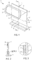
- the fin 1 and/or tube 2 may be arranged to encourage counterflow operation, e.g., in a way like that in FIG. 9 .
- the FIG. 9 embodiment is similar to that in FIGs.
- the second portion 22 of the tube 2 has parts that extend inwardly from the third and fourth portions 23, 24 along the second edge 12 of the fin 1 at an angle relative to the second edge 12 such that a central part of the second portion 22 (e.g., at the manifold 4) is located closer to the second edge 12 than outer parts of the second portion 22.
- the second portion 22 of the tube 2 has a peak or apex near a center of the second portion 22 so that vapor is encouraged to flow upwardly toward the peak or apex (in this case at the manifold 4) and liquid is encouraged to flow downwardly away from the peak or apex toward the third and fourth portions 23, 24 of the tube.
- this type of shape of the tube 2 may help encourage counterflow operation of the thermosiphon component 2.
- Embodiments like that in FIGs. 1 and 4 may also be adapted for flow of working fluid in only a single direction in the tube 2, e.g., only in a counterclockwise direction as viewed in FIGs. 1 and 4 .
- evaporated working fluid in the first portion 21 would flow toward the third portion 23, then in the third portion 23 to the second portion 22.
- Vapor that condenses in the second portion 22 i.e., liquid form working fluid
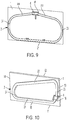
- FIG. 10 shows an embodiment in which an end of the second portion 22 adjacent the third portion 23 of the tube 2 is positioned higher than, or above, an end of the second portion 22 that is adjacent the fourth portion 24.
- This sloped arrangement of the second portion 22 e.g., where the second portion 22 is arranged at an angle relative to the second edge of the fin 1 may help encourage downward and leftward flow of condensed liquid in the second portion 22, which may help encourage counterclockwise flow of working fluid in the tube 2.
- the second portion 22 of the tube in FIG. 10 has a linear shape
- the second portion 22 may be curved, e.g., with a concave-up or concave-down curve or other shape.
- FIGs. 11 and 12 show an embodiment that is similar to that in FIGs. 4 and 7 , except that parts of the tubes 2 between the first portion 21 and third/fourth portions 23, 24 and between the second portion 22 and the third/fourth portions 23, 24 include a twist and bend.
- a twist and bend arrangement may be useful when forming a tube 2 from a multiport tube that has a generally rectangular cross section that is relatively wide and flat (or thin), e.g., like that shown in FIG. 3 . That is, bending a multiport tube that is relatively wide and flat to have bends as shown in FIGs.
- the third and fourth portions 23 24 each have a pair of 180/90 degree twist-bends 26 with an intermediate part 27 between the 180/90 degree twist bends.
- a "180/90 degree twist bend” refers to a manipulation of the tube 2 in which the tube 2 is twisted 180 degrees relative to the tube's longitudinal axis and bent 90 degrees about an axis that is perpendicular or otherwise transverse to the tube's longitudinal axis.
- the result of the twist bends is that the intermediate part 27 between the twist bends 26 is located out of the plane of the first face 16 of the fin 1 to which the first and second portions 21, 22 are attached, but lies in a plane that is parallel to the plane of the first face 16.
- the intermediate parts 27 are arranged to lie generally in a plane of an adjacent fin 1 so that a gap 5 is provided between adjacent fins 1, e.g., allowing relatively unimpeded air flow through the gap 5.
- the intermediate part 27 need not necessarily lie in the plane of an adjacent fin 1.
- FIGs. 13 and 14 show another embodiment that is similar to that in FIGs. 11 and 12 , except that the third and fourth portions 23, 24 of the tubes 2 each include a pair of 90/90 degree twist bends 26 and an intermediate part 27 between the twist bends 26.
- a "90/90 degree twist bend” refers to a manipulation of the tube 2 by which the tube 2 is twisted 90 degrees relative to the tube's longitudinal axis and bent 90 degrees about an axis that is perpendicular or otherwise transverse to the tube's longitudinal axis.
- the result is that the intermediate part 27 is arranged in a plane that is generally perpendicular to the plane of the first face 16 of the fin 1 to which the first and second portions 21, 22 are attached.
- the intermediate parts 27 may be positioned to generally occlude or block flow in any space between adjacent fins 1 at the third and fourth edges 13, 14 of the fins 1.
- air flow between fins 1 is unimpeded from along the second edge 12 of the fins 1.
- FIGs. 15 and 16 show embodiments of a coupling for joining opposite ends of a tube 2 as well as for providing a suitably sized manifold chamber 41 and a fill port 43 for providing working fluid to the tube 2.
- a coupling includes a generally tubular element sized to receive ends of the tube 2.
- the coupling has a hole 42 formed through the coupling so that a fill port 43 can be extended through the hole 42.
- a head 45 on the fill port 43 acts as a stop, preventing the fill port 43 from passing entirely through the hole 42 as well as properly positioning channels 44 within the manifold chamber 41 of the coupling.
- the fill port 43 may be secured in the hole 42 of the coupling, e.g., to provide a leak tight joint.
- the part of the fill port 43 in the manifold chamber 41 acts as a stop for the tube ends, preventing the tube ends from being inserted into the manifold chamber 41 beyond the fill port 43. This may help ensure the tube ends are suitably engaged with the coupling as well as define the size of the manifold chamber 41.
- working fluid may be provided into the tube 2 via the fill port 43 and the fill port 43 sealed, e.g., by crimping, a plug, welding, etc.
- FIG. 16 operates similar to that in FIG. 15 , but the coupling has only a single hole 42 in one side of the coupling rather than having a hole formed entirely through the coupling.
- the fill port 43 includes an end with two legs 46 that define channels 44.
- the fill port 43 can be inserted into the opening 42 until the legs 46 contact the inner side of the coupling, and then secured to the coupling.
- the fill port 43 can act as a stop for the tube ends inserted into the coupling, defining a manifold chamber 41 size.
- Working fluid may be provided to the tube 2 via the fill port 43, which is then closed.
Landscapes
- Engineering & Computer Science (AREA)
- Physics & Mathematics (AREA)
- Thermal Sciences (AREA)
- Mechanical Engineering (AREA)
- General Engineering & Computer Science (AREA)
- Life Sciences & Earth Sciences (AREA)
- Sustainable Development (AREA)
- Geometry (AREA)
- Cooling Or The Like Of Electrical Apparatus (AREA)
- Heat-Exchange Devices With Radiators And Conduit Assemblies (AREA)
Abstract
Description
- This invention relates generally to heat transfer fins or other devices that employ a two-phase thermosiphon.
- Thermosiphon devices are widely used for cooling systems, such as integrated circuits and other computer circuitry. For example,
U.S. Patent Publication 2013/0104592 ,US Patent 6,097,597 andUS Patent 8,913,386 disclose thermosiphon devices for cooling electronic components or other heat generating elements. - One aspect of the invention is a heat transfer device/assembly, preferably a heat sink, that comprises at least one planar fin having first and second opposed faces and a heat receiving portion at an edge of the planar fin and at least one thermosiphon component physically and thermally connected to the at least one planar fin and adapted to transfer heat from the heat receiving portion to other areas of the fin. The heat transfer device here and further described below thus embraces various configurations, for example, where only one or both of the first and second opposed faces has a thermosiphon component connected/attached thereto. Furthermore, several thermosiphon components per first and second opposed face are conceivable. The planar fin optionally contains or is made of an aluminum material. The opposed first and second faces are herein preferably meant to be the major front and back surfaces of the planar fin, i.e., the faces with the largest surface area. The heat receiving portion herein is meant to be a section/region of the planar fin close/closest to a heat source via which heat is taken up from the heat source and conducted into the planar fin for dissipation. The heat transfer device optionally comprises a plurality of fins with thermosiphon components spatially arranged to form a vertical or horizontal array and further optionally with an air gap or space between said individual fins with thermosiphon devices. In other words, one of the above planar fins with the at least one thermosiphon component connected/attached thereto forms an individual sub-component of the array, in which array several of said sub-components are purposefully arranged and combined to form a larger heat transfer device. For example, several of such sub-components can be stacked vertically or arranged in a row horizontally to form a subcomponent array. Optionally, in such arrangement, air gaps or spaces are formed between the arrayed sub-components.
- A further aspect of the invention that can be seen to stand-alone or optionally to be an advancement of the above aspect provides a heat transfer device that includes a planar fin having first and second opposed faces, preferably the major surfaces of the planar fin, and a heat receiving portion at an edge of the planar fin. At least one tube forming a continuous, closed loop and optionally containing a working fluid may be physically and thermally connected to the first face of the planar fin so that heat may be transferred between the fin and tube. The at least one tube and working fluid may be adapted to operate as a two-phase thermosiphon in which working fluid is evaporated in an evaporation portion of the at least one tube adjacent the heat receiving portion of the planar fin, and working fluid vapor flows in the at least one tube away from the evaporation portion for condensing. Thus, the at least one tube and working fluid may aid in transferring heat from relatively hotter areas of the fin to relatively cooler areas, thereby improving efficiency of the fin. This arrangement can be particularly useful with fins made of relatively thin and/or relatively lower thermal conductance, such as aluminum sheet materials. Accordingly, in some embodiments, the at least one tube may be arranged to equalize a temperature of the planar fin at the heat receiving portion with temperatures of the planar fin in areas away from the heat receiving portion. Part of the present invention is a heat transfer device in which the continuous, closed loop formed by the at least one tube contains a suitable working fluid but also where no working fluid is contained yet that may be added later when using the heat transfer device.
- In some embodiments, the at least one tube is adapted for flow of working fluid in only a single direction along the continuous, closed loop during operation, while in other embodiments the at least one tube is adapted for counterflow of working fluid in the continuous, closed loop during operation.
- In some embodiments and optionally combinable with all previously mentioned embodiments, the at least one tube includes a multiport tube having multiple flow channels. This may allow use of a tube that has a relatively thin wall thickness, but can withstand relatively high internal pressures.
- In some cases, the multiport tube has a linear array of the flow channels, and the multiport tube may be attached to the first face of the planar fin such that each flow channel in the linear array is adjacent the first face. A manifold portion may fluidly connect the multiple flow channels in two portions of the tube with each other, e.g., the manifold portion may physically connect ends of the tube together as well as provide a manifold chamber that permits fluid communication between flow channels. In some cases, the manifold portion is located on the continuous, closed loop where the working fluid is mostly in a liquid state, which may allow the flow channels to maintain about the same amount of liquid phase working fluid. In other cases, the manifold portion is located on the continuous, closed loop where the working fluid is mostly in a vapor state, which may allow for pressure equalization between flow channels. The manifold portion may be defined by a coupling that joins ends of the at least one tube to each other, e.g., the coupling may be formed by receiving a first end of the multiport tube into a second end of the multiport tube. Such configuration is basically a male-female coupling type, but other types, for example, a sleeve-type coupling or a butt joint are also embraced.
- In some embodiments and optionally combinable with all previously mentioned embodiments, the planar fin includes an opening in which the manifold portion is positioned, which may allow the manifold portion to be at least partially recessed relative to the face of the fin to which the tube is attached. In some embodiments and optionally combinable with all previously mentioned embodiments, the planar fin may include one or more openings to receive other components, such as electrical wiring or fasteners, and/or to permit air or other fluid flow through the opening, e.g., from a first face of the fin to the second face. In some embodiments and optionally combinable with all previously mentioned embodiments, a coupling may include a sealable port or fill port or tubular port arranged to allow evacuation of the continuous, closed loop of the tube and/or providing of working fluid to the loop. The sealable port or fill port or tubular port may be secured to an opening of the coupling and have a channel that provides fluid communication between the sealable port or fill port or tubular port and an interior space of the coupling. The sealable port or fill port or tubular port may provide a stop for tube ends received into the coupling, and/or a leg of the sealable port or fill port or tubular port that defines a channel may limit an extent to which the sealable port or fill port or tubular port is extended into the coupling. The sealable port or fill port or tubular port may include a stop to limit an extent to which the sealable port or fill port or tubular port can be extended into or through the coupling.
- In one embodiment and optionally combinable with all previously mentioned embodiments, the planar fin has a rectangular shape with a first edge opposite a second edge and a third edge opposite a fourth edge. The heat receiving portion of the fin may be at the first edge of the rectangular shape, and the at least one tube may have a first portion that extends outwardly along the first edge toward the third and fourth edges, third and fourth portions that respectively extend along the third and fourth edges toward the second edge, and a second portion extends inwardly along the second edge. In some embodiments, the first portion of the tube at least in part defines the evaporation portion, and the at least one tube is arranged so that working fluid vapor flows in the at least one tube from the evaporation portion to the third and fourth portions, and flows from the third and fourth portions to the second portion. The at least one tube may be arranged such that condensed working fluid liquid flows in the at least one tube from the second portion to the third and fourth portions, and from the third and fourth portions to the first portion. Optionally, the continuous, closed loop formed by the at least one tube has an oval-like overall shape resembling an athletic racetrack layout with two parallel linear sections connected by two curved sections. Preferably, one of the linear sections is situated in and connected to the heat receiving portion of the planar fin and the other linear section is situated away from or opposite the heat receiving portion such that heat from the heat receiving portion is transported to cooler regions of the planar fin. It is optionally conceivable that several of said racetrack loops, for example, of different sizes are combined on the respective faces of the planar fin, preferably with a higher number/density of linear sections arranged in the heat receiving portion and a lower number/density of linear sections in the away portion of the planar fin or vice versa. This concept can also be applied to all the other tube/loop layouts described herein.
- The heat transfer device may include a base that supports the planar fin and the at least one tube and transfers heat to the planar fin and the at least one tube. For example, the base may be in thermal communication with a heat source, such as an integrated circuit or other electronic device, and transfer heat from the heat source to the fin and tube. In some embodiments, the base includes a groove that receives at least a part of the first edge of the planar fin and optionally the first portion of the at least one tube, e.g., so heat can be transferred directly from the base to the fin and tube. A fin may have one or more tubes attached to it, either on the first face or second face or both faces, e.g., a first tube may be bonded to the first face of the planar fin, and a second tube may be bonded to the second face of the planar fin.
- In some embodiments, the second portion of a tube has parts that extend inwardly from the third and fourth portions along the second edge of the fin at an angle relative to the second edge such that a central part of the second portion is located closer to the second edge than outer parts of the second portion. This may aid in gravity assisted flow of liquid in the second portion toward the third and fourth portions of the tube. In another embodiment, the second portion has parts that extend inwardly from the third and fourth portions along the second edge at an angle relative to the second edge such that a part of the second portion nearest the third portion is located closer to the second edge than a part of the second portion nearest the fourth portion. This may aid in gravity assisted flow of liquid in the second portion toward the fourth portion.
- In some embodiments, the third and fourth portions may each have twist bends, e.g., a pair of 90/90 degree twist bends or 180/90 degree twist bends, and the third and fourth portions may be located away from the plane of the first face. Such twist bends may allow for various positioning and orientation of the third and fourth portions relative to the fin. For example, an intermediate part of the third and fourth portions between twist bends may be arranged in a plane parallel to the plane of the first face, e.g., to help reduce resistance or obstruction of flow between adjacent fins in an array. In other embodiments, the twist bends may position and orient parts of the third and fourth portions so as to block, occlude or resist flow between fins.
- These and other aspects of the invention will be apparent from the following description. Also, it should be appreciated that different aspects of the invention may be combined in a variety of different ways.
- The accompanying drawings, which are incorporated in and form a part of the specification, illustrate select embodiments of the present invention and, together with the description, serve to explain the principles of the inventions. In the drawings:
-
FIG. 1 is an exploded perspective view of a heat transfer device in an illustrative embodiment that incorporates aspects of the invention; -
FIG. 2 is a cross sectional view along the line 2-2 inFIG. 1 ; -
FIG. 3 is a close up view of the section labeled A inFIG. 2 ; -
FIG. 4 is a perspective view of an embodiment including a fin and thermosiphon tube having a coupling in an upper section opposite a heat receiving portion of the fin; -
FIG. 5 is a partially cut away view of a tube manifold in an illustrative embodiment; -
FIG. 6 is a sectional view of a tube manifold in an embodiment in which a tube end is formed to define a coupling part; -
FIG. 7 is a perspective view of a heat transfer assembly including a plurality of fin and tube arrangements as inFIG. 4 ; -
FIG. 8 is a side view of a heat transfer assembly in which a base is arranged vertically; -
FIG. 9 is a perspective view of a fin and thermosiphon tube embodiment in which an upper portion of the tube has a peak near a center of the fin; -
FIG. 10 is a perspective view of a fin and thermosiphon tube embodiment in which an upper portion of the tube has a peak near a side of the fin; -
FIG. 11 is a perspective view of a heat transfer assembly including a plurality of fin and tube arrangements in which the tubes have twisted and bent side portions; -
FIG. 12 is a side view of theFIG. 11 embodiment; -
FIG. 13 is a perspective view of another heat transfer assembly including a plurality of fin and tube arrangements in which the tubes have twisted and bent side portions; -
FIG. 14 is a side view of theFIG. 13 embodiment; -
FIG. 15 is a perspective view of a manifold arrangement having a working fluid delivery port; and -
FIG. 16 is a perspective view of a manifold arrangement having another embodiment of a working fluid delivery port. - Aspects of the invention are not limited in application to the details of construction and the arrangement of components set forth in the following description or illustrated in the drawings. Other embodiments may be employed and aspects of the invention may be practiced or be carried out in various ways. Also, aspects of the invention may be used alone or in any suitable combination with each other. Thus, the phraseology and terminology used herein is for the purpose of description and should not be regarded as limiting.
- Air-cooled heat sinks are commonly used to receive heat from a component, such as an integrated circuit or other electronic device, and dissipate or otherwise transfer the heat to surrounding air. Such heat sinks typically have a base that is in thermal communication with the heat source, and one or more fins that receive heat from the base and transfer the heat to surrounding air and/or other materials in the environment by convection and/or radiation. Air-cooled heat sink performance requirements often necessitate tall or otherwise large surface area heat dissipation fins to provide adequate surface area for the required level of heat dissipation. Non-thermal considerations like total material cost and the weight of the heat sink assembly often require that these heat sink fins be fabricated from relatively thin, lightweight, and inexpensive materials, such as sheet aluminum. Tall, thin aluminum fins may meet weight and cost targets, but may fail to meet thermal requirements. The limitation in terms of thermal performance for aluminum fins in this case is rooted in a low fin efficiency that a relatively tall and thin fin provides. Fin efficiency can be thought of as the fin's ability to convey heat to the upper portions of its height or otherwise to areas distant from a heat receiving area of the fin, e.g., where the fin is attached to the base. By definition, a fin of 100% efficiency is one whose temperature at areas most distant from a heat receiving area is equal to the temperature at the heat receiving area. For a simple solid fin made from sheet stock (e.g., a fin of rectangular cross-section), a designer can improve fin efficiency by specifying use of copper instead of aluminum. With all other things being equal, a heat sink with copper fins would operate at a higher fin efficiency than the same design with aluminum fins. The downside of specifying copper over aluminum is a significant increase in cost and weight, however. Similarly, the designer could specify thicker aluminum fins and thereby, all other things being equal, improve fin efficiency. Here again the downside is increased cost and weight of the thicker fins.
- To enhance fin efficiency in a heat sink assembly while reducing cost and weight, the inventors have combined a relatively thin and inexpensive fin (e.g., made of a relatively low cost and lightweight material such as aluminum) with a thermosiphon component that acts to distribute heat across the fin. By making the temperature of different portions of the fin more uniform (i.e., equalizing temperatures across the fin such that the difference between the temperatures is less than would otherwise be), efficiency of the fin can be enhanced to levels that would otherwise require a more thermally conductive (and often more expensive and/or heavier) material or construction.
FIG. 1 shows an illustrative embodiment of aheat transfer device 10, e.g., a heat sink assembly, that includes afin 1 with athermosiphon component 2 adapted to transfer heat from a heat receiving portion to other areas of thefin 1 so that temperatures of the different areas are more uniform than would be without thethermosiphon component 2. In this embodiment, thefin 1 has a planar body with first and second opposed faces 16, 17 and aheat receiving portion 15. Thefin 1 inFIG. 1 is rectangular or quadrilateral in shape, and has afirst edge 11 opposite asecond edge 12, and athird edge 13 opposite afourth edge 14, although fins with other shapes are possible. (It should be appreciated that as used herein, a "rectangular" fin need not be precisely or mathematically rectangular in shape, but rather may have edges 11-14 that are wavy or irregular in shape rather than being strictly linear, and sides of the fin need not meet to define a corner or with exactly a 90 degree angle.) The thermosiphon component includes atube 2 that is physically and thermally connected to thefirst face 16 of thefin 1 so that heat can be transferred by conduction between thetube 2 and thefin 1. Thetube 2 can be attached to thefin 1 by thermally conductive adhesive, welding, brazing, fasteners, clips, clamps or other arrangement. Thetube 2 forms a continuous, closed loop and contains a working fluid so thetube 2 can operate as a two-phase thermosiphon in which working fluid can be evaporated in one portion of the tube (an evaporation portion) and evaporated vapor can flow away from the evaporation portion for condensing in other areas of the tube 2 (a condensing portion). In this manner, thetube 2 may move heat from theheat receiving portion 15 of thefin 1 to other areas of thefin 1. In theFIG. 1 embodiment, thefin 1 is thermally connected to abase 3, e.g., by fitting thefirst edge 11 of thefin 1 in agroove 31 of thebase 3 so thefin 1 is physically supported by thebase 3. Thebase 3 is arranged to be thermally coupled to a heat source, such as an electronic device (not shown), and so thebase 3 can transfer heat from the heat source to thefin 1. The portion of thefin 1 nearest where heat is received from thebase 3 is theheat receiving portion 15, and will generally have a higher temperature as compared to other areas of thefin 1 in the absence of the thermosiphon component. Thetube 2 is arranged to receive heat in a first portion 21 (an evaporation portion) near theheat receiving portion 15 which evaporates working fluid in thetube 2. Evaporated working fluid is able to flow away from thefirst portion 21 to other portions of the tube, such as second, third and/or fourth portions 22-24, where vapor condenses back to liquid. The condensed working fluid can flow back toward the first portion 21 (by gravity) for later evaporation. This evaporation/condensation cycle moves heat from theheat receiving portion 15 of thefin 1 to other areas of thefin 1 away from theheat receiving portion 15 and thus helps to equalize temperatures across areas of thefin 1, thereby improving efficiency of thefin 1. - While the
tube 2 may have a single flow channel in the closed loop, atube 2 that includes multiple flow channels may provide improved performance with respect to tube structure in terms of ability to withstand internal pressure. This is due largely to the internal web(s) of the multiple flow channel tube. This improved structure allows for thinner tube walls, enabling designs of lower weight and lower cost. For example,FIG. 2 shows a cross sectional view along the line 2-2 inFIG. 1 and illustrates that thetube 2 is a multiport tube having a plurality of flow channels. As can be seen in the close up view ofFIG. 3 , themultiport tube 2 may have a linear array offlow channels 25, and thetube 2 may be attached to thefin 1 so that each of theflow channels 25 in the linear array is adjacent thefirst face 16 of thefin 1. It should be understood, however, that other arrangements are possible. Thetube 2 may have a plurality offlow channels 25, but not necessarily all of the flow channels need be adjacent theface 16 of thefin 1. Instead, someflow channels 25 may be spaced from theface 16, e.g., separated from theface 16 by anotherflow channel 25 or an air gap. Also, flowchannels 25 of atube 2 need not be arranged in a linear array, but could be arranged in any suitable way. Moreover, whileFIG. 1 shows an arrangement with onetube 2, two ormore tubes 2 may be provided on aface 16 of the fin 1 (each tube having one or more flow channels), and/or one ormore tubes 2 may be provided on bothfaces fin 1. - In some embodiments, a
thermosiphon component tube 2 may include a manifold that allows for fluid communication betweenflow channels 25 in atube 2 ortubes 2. For example,FIG. 4 shows aheat transfer device 10 that includes amanifold 4 arranged at an upper portion of thetube 2. In this location, themanifold 4 is positioned on the continuous, closed loop of thetube 2 where the working fluid is mostly in a vapor state. As shown in the partial cut away view ofFIG. 5 , themanifold 4 includes achamber 41 arranged so that each of theflow channels 25 of thetube 2 can fluidly communicate with each other. This may allow for pressure equalization between theflow channels 25 and/or other fluid communication, e.g., so eachflow channel 25 has approximately a same amount of liquid form working fluid. Themanifold 4 is not limited to being positioned on the closed loop of thetube 2 where working fluid is mostly in a vapor state, but may be positioned where the working fluid is mostly in a liquid state, such as at a location between thefirst portion 21 of thetube 2 and thethird portion 23 as shown inFIG. 4 . While the location of amanifold 4 in different areas of the closed loop of thetube 2 may provide for different operative effects, themanifold 4 also provides manufacturing benefits as it can be adapted to include a tube or other structure to serve as a port for evacuation of the loop and/or for injection of refrigerant or other working fluid into the loop. Also, amanifold 4 may be arranged to joinmultiple tubes 2 together, both physically and to provide fluid coupling between flow channels in thetubes 2. For example, multiple, singleflow channel tubes 2 may be provided on a face of afin 1, and ends of thetubes 2 may be coupled to amanifold 4. - In some embodiments, a coupling that joins ends of a
tube 2 together may provide amanifold 4. In theFIG. 5 embodiment, the a sleeve-type coupling is arranged to receive opposite ends of thetube 2. The coupling may include stops at an inner space of the coupling to limit the insertion depth for the ends of thetube 2 so that the tube ends are separated from each other to define asuitable manifold chamber 41. In another embodiment shown inFIG. 6 , amanifold 4 is defined by one end of thetube 2 which has been enlarged so that the other end of thetube 2 can be received within the enlarged end of thetube 2. Such relative enlargement can be formed by expanding the end of a tube, and/or swaging or otherwise reducing the size of the other end of thetube 2. Amanifold chamber 41 may be defined by one of the tube ends, e.g., by cutting or otherwise removing portions of the separating walls or webs betweenflow channels 25, if thetube 2 is a multiport tube. Alternately, nomanifold chamber 41 need be provided, and the webs betweenflow channels 25 of the receiving tube end may contact or otherwise meet corresponding webs from the received tube end (e.g., the webs in the tube portion on the right inFIG. 6 may be extended to the left so as to contact webs in the tube portion on the left inFIG. 6 . This allowsflow channels 25 to communicate, but without amanifold chamber 41. In another embodiment, ends of thetube 2 may be joined in a butt-joint where the opposed tube ends are positioned against each other and secured in a suitable way, such as by welding, brazing, adhesive, etc. Thus, no coupling need be provided, and amanifold 4 may be defined by interior spaces of the tube ends. As in theFIG. 6 embodiment, amanifold chamber 41 may be defined in a butt-type connection by removing walls or webs betweenflow channels 25 in one or both tube ends so a suitably sizedmanifold chamber 41 is provided. Or, nomanifold chamber 41 need be provided and instead ends of the tube butt-joined so corresponding webs are in contact with each other. -
FIGs. 4 and 5 show that the coupling which forms themanifold 4 includes afill port 43 for providing working fluid in thetube 2. That is, thetube 2 may be assembled with the coupling to provide a sealed loop for the working fluid, after which thetube 2 may be evacuated and working fluid provided to the tube interior via thefill port 43. Thefill port 43 may be arranged in different ways, and more detail regarding illustrative embodiments is included below. In the embodiment ofFIG. 4 , thefill port 43 includes a conduit that extends from the coupling that allows liquid/vapor phase working fluid to be introduced into thetube 2 and then thefill port 43 sealed closed, such as by a plug, welding, crimping, etc. In some cases, thefill port 43 may be implemented as an opening into the continuous, closed loop of thetube 2, e.g., at amanifold 4, that can be sealed by a plug, welding, adhesive, etc. -
FIG. 4 also shows that thefin 1 includes anopening 18 in which themanifold 4 is positioned. In cases where themanifold 4 is formed by a coupling or other element having a size larger than the tube ends joined to the coupling, theopening 18 may receive a portion of the coupling so that thetube 2 may suitably contact theface 16 of thefin 1. Thefin 1 inFIG. 4 has other openings, which may provide different functions. For example, openings near theheat receiving portion 15 of thefin 1 are formed to defineclips 19 used to secure a part of thetube 2 to thefin 1. Such clips or other similar features may be formed in other ways and in other areas of thefin 1. Also, notches or openings at the third andfourth edges fin 1 are arranged near the third andfourth portions tube 2. These openings may allow portions of the tube at the openings to be bent or otherwise offset so as to reduce resistance to air flow across thefins 1, e.g., in a right-to-left direction inFIG. 4 .Openings 18 may be provided in thefin 1 in other areas and/or for other purposes, such as allowing electrical wiring to pass through the opening, fasteners or other components to be at least partially received into theopening 18, allowing air or other fluid flow through the opening 18 (e.g., from afirst face 16 to asecond face 17 of the fin 1), etc. - While the embodiments of
FIGs. 1 and4 are shown with asingle fin 1,heat transfer devices 10 may include any suitable number offins 1 and/orthermosiphon component tubes 2. For example,FIG. 7 shows aheat transfer device 10 that includes abase 3 withmultiple grooves 31 that each receives a portion of one of aplurality fins 1 arranged similarly to that inFIG. 4 . An air gap or space may be provided betweenadjacent fins 1 to allow air flow between thefins 1, e.g., in a direction parallel to the planes of thefins 1. Note that thegrooves 31 in the base ofFIG. 7 are arranged to receive a portion of afin 1 as well as a portion of thetube 2. This may help transfer heat directly from thebase 3 to thetube 2 and working fluid, but is not required. While theFIG. 7 embodiment is arranged to operate with the force of gravity oriented downwardly in the plane of the drawing ofFIG. 7 and perpendicular to the generally horizontalplanar base 3, i.e., along the arrow g1 inFIG. 7 , other arrangements are possible. For example, theFIG. 7 embodiment could be reoriented with respect to the force of gravity arranged as shown by the arrow g2 inFIG. 7 , i.e., so that thebase 3 is oriented vertically with both the plane of thebase 3 and thegrooves 31 parallel to the force of gravity along arrow g2 and so that thethird portions 23 of thetubes 2 andmanifolds 4 are located below thefourth portions 24 of the tubes 2 (or vice versa). In another embodiment,FIG. 8 shows a side view of aheat transfer device 10 that is arranged similarly to theFIG. 7 embodiment, but is adapted to operate with the plane of thebase 3 oriented vertically and parallel to the force of gravity along the arrow g3 and thegrooves 31 of thebase 3 oriented perpendicular to the force of gravity g3. In this embodiment ofFIG. 8 , each of the fins 1 (and as necessary, tubes 2) is bent so that portions of thefins 1 andtubes 2 that are farthest from thebase 3 are located above portions of thefins 1 andtubes 2 that are nearest thebase 3. In other words, in this embodiment, the fins 1 (andtubes 2 as necessary) are bent or otherwise formed so that thesecond portions 22 of thetubes 2 are positioned above correspondingfirst portions 21 of thetubes 2. This allows for the gravity-assisted flow of working fluid in thetubes 2. - The embodiments of
FIGs. 1 and4 may be arranged so that working fluid moves in the closed loop of thetubes 2 in either a counterflow-type flow during operation, or so that the working fluid flows in only a single direction along the closed loop of thetubes 2. In a counterflow-type operation, working fluid liquid may be evaporated in thefirst portion 1 of theFIGs. 1 and4 embodiments, and the evaporated vapor may flow outwardly along thefirst edge 11 of thefin 1 toward the third andfourth edges fourth portions tube 2. The vapor may flow upwardly in the third andfourth portions fourth edges fin 1, and then inwardly in thesecond portion 22 of the tube along thesecond edge 12 of thefin 1. The vapor may condense in the second portion 22 (and/or in the third andfourth portions 23, 24) of thetube 2, and the condensed liquid may flow outwardly in thesecond portion 22, and downwardly in the third andfourth portions first portion 21 of the tube. Since vapor and liquid flow in opposite directions in thetube 2, this type of operation is referred to as counterflow operation. In some embodiments, thefin 1 and/ortube 2 may be arranged to encourage counterflow operation, e.g., in a way like that inFIG. 9 . TheFIG. 9 embodiment is similar to that inFIGs. 1 and4 , except that thesecond portion 22 of thetube 2 has parts that extend inwardly from the third andfourth portions second edge 12 of thefin 1 at an angle relative to thesecond edge 12 such that a central part of the second portion 22 (e.g., at the manifold 4) is located closer to thesecond edge 12 than outer parts of thesecond portion 22. In other words, thesecond portion 22 of thetube 2 has a peak or apex near a center of thesecond portion 22 so that vapor is encouraged to flow upwardly toward the peak or apex (in this case at the manifold 4) and liquid is encouraged to flow downwardly away from the peak or apex toward the third andfourth portions tube 2 may help encourage counterflow operation of thethermosiphon component 2. - Embodiments like that in
FIGs. 1 and4 may also be adapted for flow of working fluid in only a single direction in thetube 2, e.g., only in a counterclockwise direction as viewed inFIGs. 1 and4 . In this case, evaporated working fluid in thefirst portion 21 would flow toward thethird portion 23, then in thethird portion 23 to thesecond portion 22. Vapor that condenses in the second portion 22 (i.e., liquid form working fluid) may flow toward thefourth portion 24 and then downwardly into thefirst portion 21 for evaporation again. While the description above indicates counterclockwise flow in thetubes 2 ofFIGs. 1 and4 , flow in a clockwise direction is equally possible. Again, suitable arrangement of thefin 1 and/ortubes 2 may help encourage single direction loop flow of working fluid during operation. For example,FIG. 10 shows an embodiment in which an end of thesecond portion 22 adjacent thethird portion 23 of thetube 2 is positioned higher than, or above, an end of thesecond portion 22 that is adjacent thefourth portion 24. This sloped arrangement of the second portion 22 (e.g., where thesecond portion 22 is arranged at an angle relative to the second edge of the fin 1) may help encourage downward and leftward flow of condensed liquid in thesecond portion 22, which may help encourage counterclockwise flow of working fluid in thetube 2. Although thesecond portion 22 of the tube inFIG. 10 has a linear shape, thesecond portion 22 may be curved, e.g., with a concave-up or concave-down curve or other shape. -
FIGs. 11 and 12 show an embodiment that is similar to that inFIGs. 4 and7 , except that parts of thetubes 2 between thefirst portion 21 and third/fourth portions second portion 22 and the third/fourth portions tube 2 from a multiport tube that has a generally rectangular cross section that is relatively wide and flat (or thin), e.g., like that shown inFIG. 3 . That is, bending a multiport tube that is relatively wide and flat to have bends as shown inFIGs. 1 and4 may be difficult, may not be possible with certain tube materials or geometries, and/or may make some flow loops around the tube longer than others (e.g., inner loops may be unsuitably shorter than outer loops). By providing a twist and bend at transitions between tube portions, a multiport tube need not be bent entirely in the plane of its wide dimension as inFIGs. 1 and4 , and may allow for the use of tube materials and geometries that would otherwise not be possible. In the embodiment ofFIGs. 11 and 12 , the third andfourth portions 23 24 each have a pair of 180/90 degree twist-bends 26 with anintermediate part 27 between the 180/90 degree twist bends. A "180/90 degree twist bend" refers to a manipulation of thetube 2 in which thetube 2 is twisted 180 degrees relative to the tube's longitudinal axis and bent 90 degrees about an axis that is perpendicular or otherwise transverse to the tube's longitudinal axis. As can be seen inFIG. 12 , the result of the twist bends is that theintermediate part 27 between the twist bends 26 is located out of the plane of thefirst face 16 of thefin 1 to which the first andsecond portions first face 16. In this embodiment, theintermediate parts 27 are arranged to lie generally in a plane of anadjacent fin 1 so that agap 5 is provided betweenadjacent fins 1, e.g., allowing relatively unimpeded air flow through thegap 5. Of course, other arrangements are possible, as theintermediate part 27 need not necessarily lie in the plane of anadjacent fin 1. -
FIGs. 13 and 14 show another embodiment that is similar to that inFIGs. 11 and 12 , except that the third andfourth portions tubes 2 each include a pair of 90/90 degree twist bends 26 and anintermediate part 27 between the twist bends 26. Similar to above, a "90/90 degree twist bend" refers to a manipulation of thetube 2 by which thetube 2 is twisted 90 degrees relative to the tube's longitudinal axis and bent 90 degrees about an axis that is perpendicular or otherwise transverse to the tube's longitudinal axis. The result is that theintermediate part 27 is arranged in a plane that is generally perpendicular to the plane of thefirst face 16 of thefin 1 to which the first andsecond portions intermediate parts 27 may be positioned to generally occlude or block flow in any space betweenadjacent fins 1 at the third andfourth edges fins 1. Of course, air flow betweenfins 1 is unimpeded from along thesecond edge 12 of thefins 1. -
FIGs. 15 and 16 show embodiments of a coupling for joining opposite ends of atube 2 as well as for providing a suitably sizedmanifold chamber 41 and afill port 43 for providing working fluid to thetube 2. InFIG. 15 , a coupling includes a generally tubular element sized to receive ends of thetube 2. The coupling has ahole 42 formed through the coupling so that afill port 43 can be extended through thehole 42. A head 45 on thefill port 43 acts as a stop, preventing thefill port 43 from passing entirely through thehole 42 as well as properly positioningchannels 44 within themanifold chamber 41 of the coupling. Thefill port 43 may be secured in thehole 42 of the coupling, e.g., to provide a leak tight joint. Note that the part of thefill port 43 in themanifold chamber 41 acts as a stop for the tube ends, preventing the tube ends from being inserted into themanifold chamber 41 beyond thefill port 43. This may help ensure the tube ends are suitably engaged with the coupling as well as define the size of themanifold chamber 41. With thefill port 43 and tube ends secured to the coupling, e.g., by brazing, welding, adhesive, etc., working fluid may be provided into thetube 2 via thefill port 43 and thefill port 43 sealed, e.g., by crimping, a plug, welding, etc. - The embodiment of
FIG. 16 operates similar to that inFIG. 15 , but the coupling has only asingle hole 42 in one side of the coupling rather than having a hole formed entirely through the coupling. Thefill port 43 includes an end with twolegs 46 that definechannels 44. Thus, thefill port 43 can be inserted into theopening 42 until thelegs 46 contact the inner side of the coupling, and then secured to the coupling. Again, thefill port 43 can act as a stop for the tube ends inserted into the coupling, defining amanifold chamber 41 size. Working fluid may be provided to thetube 2 via thefill port 43, which is then closed. - The embodiments provided herein are not intended to be exhaustive or to limit the invention to a precise form disclosed, and many modifications and variations are possible in light of the above teachings. The embodiments were chosen and described in order to best explain the principles of the invention and its practical application to thereby enable others skilled in the art to best utilize the invention in various embodiments and with various modifications as are suited to the particular use contemplated. Although the above description contains many specifications, these should not be construed as limitations on the scope of the invention, but rather as an exemplification of alternative embodiments thereof.
- The indefinite articles "a" and "an," as used herein in the specification and in the claims, unless clearly indicated to the contrary, should be understood to mean "at least one."
- The phrase "and/or," as used herein in the specification and in the claims, should be understood to mean "either or both" of the elements so conjoined, i.e., elements that are conjunctively present in some cases and disjunctively present in other cases. Multiple elements listed with "and/or" should be construed in the same fashion, i.e., "one or more" of the elements so conjoined. Other elements may optionally be present other than the elements specifically identified by the "and/or" clause, whether related or unrelated to those elements specifically identified.
- The use of "including," "comprising," "having," "containing," "involving," and/or variations thereof herein, is meant to encompass the items listed thereafter and equivalents thereof as well as additional items.
- It should also be understood that, unless clearly indicated to the contrary, in any methods claimed herein that include more than one step or act, the order of the steps or acts of the method is not necessarily limited to the order in which the steps or acts of the method are recited.
- While aspects of the invention have been described with reference to various illustrative embodiments, such aspects are not limited to the embodiments described. Thus, it is evident that many alternatives, modifications, and variations of the embodiments described will be apparent to those skilled in the art. Accordingly, embodiments as set forth herein are intended to be illustrative, not limiting. Various changes may be made without departing from the spirit of aspects of the invention.
Claims (15)
- A heat transfer device (10) comprising:at least one planar fin (1) having first and second opposed faces (16, 17) and a heat receiving portion (15) at an edge of the planar fin; andat least one thermosiphon component (2) physically and thermally connected to the at least one planar fin and adapted to transfer heat from the heat receiving portion to other areas of the fin,the heat transfer device optionally comprising a plurality of fins with thermosiphon components spatially arranged to form a vertical or horizontal array and further optionally with an air gap or space between said individual fins with thermosiphon devices.
- The heat transfer device (10) according to claim 1, wherein:
the at least one thermosiphon component includes at least one tube (2) forming a continuous, closed loop and optionally containing a working fluid, the at least one tube being physically and thermally connected to the first face and/or the second face of the planar fin, and the at least one tube and working fluid adapted to operate as a two-phase thermosiphon in which working fluid is evaporated in an evaporation portion of the at least one tube adjacent the heat receiving portion of the planar fin, and working fluid vapor flows in the at least one tube away from the evaporation portion for condensing. - The heat transfer device of claim 2, whereina) the at least one tube is arranged to equalize a temperature of the planar fin at the heat receiving portion with temperatures of the planar fin in areas away from the heat receiving portion, and/ora) the at least one tube includes a first tube bonded to the first face of the planar fin, and a second tube bonded to the second face of the planar fin, and/orb) the planar fin includes an opening arranged to receive a portion of the at least one tube or other component, or arranged to permit air flow through the opening, and/orc) the at least one tube is adapted for flow of working fluid in only a single direction along the continuous, closed loop during operation, ord) the at least one tube is adapted for counterflow of working fluid in the continuous, closed loop during operation, or
- The heat transfer device of claim 2, wherein
the at least one tube includes a multiport tube having multiple flow channels. - The heat transfer device of claim 4, wherein the multiport tube has a linear array of the flow channels, and wherein the multiport tube is attached to the first face of the planar fin such that each flow channel in the linear array is adjacent the first face.
- The heat transfer device of claim 4, wherein the multiport tube includes a manifold (4) portion that fluidly connects the multiple flow channels with each other.
- The heat transfer device of claim 6, wherein the manifold portion is located on the continuous, closed loop formed by the at least one tube where the working fluid is mostly in a liquid state, or
wherein the manifold portion is located on the continuous, closed loop formed by the at least one tube where the working fluid is mostly in a vapor state, and/or
wherein the planar fin includes an opening in which the manifold portion is positioned. - The heat transfer device of claim 6, wherein the manifold portion is defined by a coupling that joins ends of the at least one tube to each other, optionally
wherein the coupling is formed by receiving a first end of the multiport tube into a second end of the multiport tube or formed by a sleeve-type coupling or a butt joint. - The heat transfer device of any one of claims 2 to 8, wherein the planar fin has a rectangular shape with a first edge opposite a second edge and a third edge opposite a fourth edge, the heat receiving portion being at the first edge of the rectangular shape, and wherein the at least one tube has a first portion that extends outwardly along the first edge toward the third and fourth edges, third and fourth portions that respectively extend along the third and fourth edges toward the second edge, and a second portion extends inwardly along the second edge.
- The heat transfer device of claim 9, wherein the second portion has parts that extend inwardly from the third and fourth portions along the second edge at an angle relative to the second edge such that a central part of the second portion is located closer to the second edge than outer parts of the second portion, or wherein the second portion has parts that extend inwardly from the third and fourth portions along the second edge at an angle relative to the second edge such that a part of the second portion nearest the third portion is located closer to the second edge than a part of the second portion nearest the fourth portion.
- The heat transfer device of claim 9, wherein the third and fourth portions each have at least one twist bend and the third and fourth portions are located away from the plane of the first face, optionally
wherein the third and fourth portions each have a pair of 180/90 degree twist bends with an intermediate part between the twist bends, wherein the intermediate part of the third and fourth portions is arranged in a plane parallel to the plane of the first face, or wherein the third and fourth portions each have a pair of 90/90 degree twist bends. - The heat transfer device of claim 9, wherein the first portion at least in part defines the evaporation portion, and the at least one tube is arranged so that working fluid vapor flows in the at least one tube from the evaporation portion to the third and fourth portions, and flows from the third and fourth portions to the second portion, optionally
wherein the at least one tube is arranged such that condensed working fluid liquid flows in the at least one tube from the second portion to the third and fourth portions, and from the third and fourth portions to the first portion. - The heat transfer device of claim 9, further comprising a base (3) that supports the planar fin and the at least one tube and transfers heat to the planar fin and the at least one tube, optionally
wherein the base includes at least one groove (31) that receives at least a part of the first edge of the planar fin and optionally the first portion of the at least one tube. - The heat transfer device of any one of claims 2 to 13, wherein the at least one tube includes a sealable/fill port (43), optionally a tubular port, for evacuating and/or providing a working fluid to the continuous, closed loop.
- The heat transfer device of claim 14, wherein the at least one tube includes a manifold (4) portion that fluidly connects two ends of the at least one tube with each other, the manifold portion including the sealable port, optionally
wherein the manifold portion includes a coupling that joins the two ends and the sealable port includes a tubular element attached to an opening in the coupling, the tubular element including a channel in fluid communication with an interior space of the coupling.
Applications Claiming Priority (1)
| Application Number | Priority Date | Filing Date | Title |
|---|---|---|---|
| US16/531,517 US11454462B2 (en) | 2019-08-05 | 2019-08-05 | Heat dissipating fin with thermosiphon |
Publications (2)
| Publication Number | Publication Date |
|---|---|
| EP3772629A1 true EP3772629A1 (en) | 2021-02-10 |
| EP3772629B1 EP3772629B1 (en) | 2024-05-01 |
Family
ID=69770769
Family Applications (1)
| Application Number | Title | Priority Date | Filing Date |
|---|---|---|---|
| EP20161165.4A Active EP3772629B1 (en) | 2019-08-05 | 2020-03-05 | Heat dissipating fin with thermosiphon |
Country Status (3)
| Country | Link |
|---|---|
| US (1) | US11454462B2 (en) |
| EP (1) | EP3772629B1 (en) |
| CN (1) | CN112325682A (en) |
Families Citing this family (4)
| Publication number | Priority date | Publication date | Assignee | Title |
|---|---|---|---|---|
| TWI775590B (en) * | 2021-09-03 | 2022-08-21 | 營邦企業股份有限公司 | Looping flow-field heat sink |
| US20230225080A1 (en) * | 2022-01-12 | 2023-07-13 | Arista Networks, Inc. | Hybrid heatsink system |
| US12474070B2 (en) | 2022-04-28 | 2025-11-18 | Tyco Fire & Security Gmbh | Direct evaporative cooling system for data center with fan and water optimization |
| EP4387405A1 (en) | 2022-12-14 | 2024-06-19 | Huawei Technologies Co., Ltd. | Apparatus for transferring heat from a heat source to air |
Citations (6)
| Publication number | Priority date | Publication date | Assignee | Title |
|---|---|---|---|---|
| US6097597A (en) | 1998-06-30 | 2000-08-01 | Mitsubishi Denki Kabushiki Kaisha | Thermo-siphon and manufacturing method of thermo-siphon and information processing apparatus |
| WO2011035943A2 (en) * | 2009-09-28 | 2011-03-31 | Abb Research Ltd | Cooling module for cooling electronic components |
| US20130104592A1 (en) | 2011-10-31 | 2013-05-02 | Abb Technology Ag | Cabinet with modules having a thermosiphon cooler arrangement |
| US20130112372A1 (en) * | 2011-11-08 | 2013-05-09 | Electronics And Telecommunications Research Institute | Flat heat pipe and fabrication method thereof |
| EP2677261A1 (en) * | 2012-06-20 | 2013-12-25 | ABB Technology AG | Two-phase cooling system for electronic components |
| KR20160064927A (en) * | 2014-11-28 | 2016-06-08 | 최영환 | Heat source pipe, and floor heating and cooling system |
Family Cites Families (15)
| Publication number | Priority date | Publication date | Assignee | Title |
|---|---|---|---|---|
| US4449578A (en) * | 1980-06-16 | 1984-05-22 | Showa Aluminum Corporation | Device for releasing heat |
| US4588023A (en) * | 1980-06-16 | 1986-05-13 | Showa Aluminum Corporation | Device for releasing heat |
| JP3438087B2 (en) * | 1995-02-16 | 2003-08-18 | アクトロニクス株式会社 | Ribbon plate heat pipe |
| TWM309091U (en) * | 2004-03-15 | 2007-04-01 | Delta Electronics Inc | Heat sink |
| US7420810B2 (en) * | 2006-09-12 | 2008-09-02 | Graftech International Holdings, Inc. | Base heat spreader with fins |
| CN101621909B (en) * | 2008-07-04 | 2012-03-21 | 富准精密工业(深圳)有限公司 | Heat sink |
| US9200850B2 (en) * | 2011-07-25 | 2015-12-01 | Tai-Her Yang | Closed-loop temperature equalization device having a heat releasing system structured by multiple flowpaths |
| CN103322844B (en) * | 2013-06-27 | 2015-01-21 | 高禹丰 | Heat exchanging device |
| CN103822516A (en) * | 2014-03-10 | 2014-05-28 | 吴鸿平 | Stick tube type fluid heat exchanger and manufacturing method thereof |
| JP2017534826A (en) * | 2014-09-15 | 2017-11-24 | アアヴィッド・サーマロイ・エルエルシー | Thermosiphon with a bent tube |
| JP2018513342A (en) * | 2015-04-21 | 2018-05-24 | アアヴィッド・サーマロイ・エルエルシー | Thermosiphon with multi-port tube and flow arrangement |
| CN105140194B (en) * | 2015-07-03 | 2018-02-02 | 浙江嘉熙科技有限公司 | Hot superconducting radiator and its manufacture method |
| TWI685638B (en) * | 2018-09-14 | 2020-02-21 | 財團法人工業技術研究院 | Three dimensional pulsating heat pipe, three dimensional pulsating heat pipe assembly and heat dissipation module |
| TWI691830B (en) * | 2018-12-05 | 2020-04-21 | 宏碁股份有限公司 | Cooling module |
| CN109341401B (en) * | 2018-12-07 | 2023-11-17 | 常州恒创热管理有限公司 | Radiating fin and cascade caulking groove radiator |
-
2019
- 2019-08-05 US US16/531,517 patent/US11454462B2/en active Active
- 2019-12-06 CN CN201911242036.XA patent/CN112325682A/en active Pending
-
2020
- 2020-03-05 EP EP20161165.4A patent/EP3772629B1/en active Active
Patent Citations (7)
| Publication number | Priority date | Publication date | Assignee | Title |
|---|---|---|---|---|
| US6097597A (en) | 1998-06-30 | 2000-08-01 | Mitsubishi Denki Kabushiki Kaisha | Thermo-siphon and manufacturing method of thermo-siphon and information processing apparatus |
| WO2011035943A2 (en) * | 2009-09-28 | 2011-03-31 | Abb Research Ltd | Cooling module for cooling electronic components |
| US8913386B2 (en) | 2009-09-28 | 2014-12-16 | Abb Research Ltd. | Cooling module for cooling electronic components |
| US20130104592A1 (en) | 2011-10-31 | 2013-05-02 | Abb Technology Ag | Cabinet with modules having a thermosiphon cooler arrangement |
| US20130112372A1 (en) * | 2011-11-08 | 2013-05-09 | Electronics And Telecommunications Research Institute | Flat heat pipe and fabrication method thereof |
| EP2677261A1 (en) * | 2012-06-20 | 2013-12-25 | ABB Technology AG | Two-phase cooling system for electronic components |
| KR20160064927A (en) * | 2014-11-28 | 2016-06-08 | 최영환 | Heat source pipe, and floor heating and cooling system |
Also Published As
| Publication number | Publication date |
|---|---|
| US20210041191A1 (en) | 2021-02-11 |
| US11454462B2 (en) | 2022-09-27 |
| EP3772629B1 (en) | 2024-05-01 |
| CN112325682A (en) | 2021-02-05 |
Similar Documents
| Publication | Publication Date | Title |
|---|---|---|
| US11725883B2 (en) | Heat sink | |
| EP3772629B1 (en) | Heat dissipating fin with thermosiphon | |
| US12504235B2 (en) | Vapor chamber heatsink assembly | |
| US9032743B2 (en) | Heat exchanger | |
| US20250052511A1 (en) | Vapor chamber heatsink assembly | |
| US20160061532A1 (en) | Evaporator and condenser section structure for thermosiphon | |
| US10989483B2 (en) | Thermosiphon with multiport tube and flow arrangement | |
| CN108801012B (en) | Thermosiphon device with integral components | |
| CN106922108A (en) | Cooling component and its manufacture method | |
| JP5344994B2 (en) | Heat sink device | |
| US20080055855A1 (en) | Heat sink for electronic components | |
| EP3723463A1 (en) | Heat exchanger with integrated two-phase heat spreader | |
| CN111587352A (en) | Boiling type refrigerator | |
| CN111504111A (en) | Evaporator and method of manufacture | |
| US12463112B2 (en) | Cooling device | |
| KR102222507B1 (en) | Heat exchanger | |
| JP2016205745A (en) | Heat pipe type heat sink | |
| TWI843632B (en) | Radiator | |
| KR100728358B1 (en) | Heat shield | |
| CN114166050A (en) | Heat pipe radiator, refrigerator, wine cabinet, dehumidifier and water dispenser |
Legal Events
| Date | Code | Title | Description |
|---|---|---|---|
| PUAI | Public reference made under article 153(3) epc to a published international application that has entered the european phase |
Free format text: ORIGINAL CODE: 0009012 |
|
| STAA | Information on the status of an ep patent application or granted ep patent |
Free format text: STATUS: REQUEST FOR EXAMINATION WAS MADE |
|
| 17P | Request for examination filed |
Effective date: 20200305 |
|
| AK | Designated contracting states |
Kind code of ref document: A1 Designated state(s): AL AT BE BG CH CY CZ DE DK EE ES FI FR GB GR HR HU IE IS IT LI LT LU LV MC MK MT NL NO PL PT RO RS SE SI SK SM TR |
|
| AX | Request for extension of the european patent |
Extension state: BA ME |
|
| GRAP | Despatch of communication of intention to grant a patent |
Free format text: ORIGINAL CODE: EPIDOSNIGR1 |
|
| STAA | Information on the status of an ep patent application or granted ep patent |
Free format text: STATUS: GRANT OF PATENT IS INTENDED |
|
| INTG | Intention to grant announced |
Effective date: 20230926 |
|
| GRAS | Grant fee paid |
Free format text: ORIGINAL CODE: EPIDOSNIGR3 |
|
| P01 | Opt-out of the competence of the unified patent court (upc) registered |
Effective date: 20240130 |
|
| GRAA | (expected) grant |
Free format text: ORIGINAL CODE: 0009210 |
|
| STAA | Information on the status of an ep patent application or granted ep patent |
Free format text: STATUS: THE PATENT HAS BEEN GRANTED |
|
| AK | Designated contracting states |
Kind code of ref document: B1 Designated state(s): AL AT BE BG CH CY CZ DE DK EE ES FI FR GB GR HR HU IE IS IT LI LT LU LV MC MK MT NL NO PL PT RO RS SE SI SK SM TR |
|
| REG | Reference to a national code |
Ref country code: GB Ref legal event code: FG4D |
|
| REG | Reference to a national code |
Ref country code: CH Ref legal event code: EP |
|
| REG | Reference to a national code |
Ref country code: IE Ref legal event code: FG4D |
|
| REG | Reference to a national code |
Ref country code: DE Ref legal event code: R096 Ref document number: 602020029885 Country of ref document: DE |
|
| REG | Reference to a national code |
Ref country code: LT Ref legal event code: MG9D |
|
| REG | Reference to a national code |
Ref country code: NL Ref legal event code: MP Effective date: 20240501 |
|
| PG25 | Lapsed in a contracting state [announced via postgrant information from national office to epo] |
Ref country code: IS Free format text: LAPSE BECAUSE OF FAILURE TO SUBMIT A TRANSLATION OF THE DESCRIPTION OR TO PAY THE FEE WITHIN THE PRESCRIBED TIME-LIMIT Effective date: 20240901 |
|
| PG25 | Lapsed in a contracting state [announced via postgrant information from national office to epo] |
Ref country code: BG Free format text: LAPSE BECAUSE OF FAILURE TO SUBMIT A TRANSLATION OF THE DESCRIPTION OR TO PAY THE FEE WITHIN THE PRESCRIBED TIME-LIMIT Effective date: 20240501 |
|
| PG25 | Lapsed in a contracting state [announced via postgrant information from national office to epo] |
Ref country code: HR Free format text: LAPSE BECAUSE OF FAILURE TO SUBMIT A TRANSLATION OF THE DESCRIPTION OR TO PAY THE FEE WITHIN THE PRESCRIBED TIME-LIMIT Effective date: 20240501 Ref country code: FI Free format text: LAPSE BECAUSE OF FAILURE TO SUBMIT A TRANSLATION OF THE DESCRIPTION OR TO PAY THE FEE WITHIN THE PRESCRIBED TIME-LIMIT Effective date: 20240501 |
|
| PG25 | Lapsed in a contracting state [announced via postgrant information from national office to epo] |
Ref country code: GR Free format text: LAPSE BECAUSE OF FAILURE TO SUBMIT A TRANSLATION OF THE DESCRIPTION OR TO PAY THE FEE WITHIN THE PRESCRIBED TIME-LIMIT Effective date: 20240802 |
|
| PG25 | Lapsed in a contracting state [announced via postgrant information from national office to epo] |
Ref country code: PT Free format text: LAPSE BECAUSE OF FAILURE TO SUBMIT A TRANSLATION OF THE DESCRIPTION OR TO PAY THE FEE WITHIN THE PRESCRIBED TIME-LIMIT Effective date: 20240902 |
|
| REG | Reference to a national code |
Ref country code: AT Ref legal event code: MK05 Ref document number: 1682871 Country of ref document: AT Kind code of ref document: T Effective date: 20240501 |
|
| PG25 | Lapsed in a contracting state [announced via postgrant information from national office to epo] |
Ref country code: NL Free format text: LAPSE BECAUSE OF FAILURE TO SUBMIT A TRANSLATION OF THE DESCRIPTION OR TO PAY THE FEE WITHIN THE PRESCRIBED TIME-LIMIT Effective date: 20240501 |
|
| PG25 | Lapsed in a contracting state [announced via postgrant information from national office to epo] |
Ref country code: ES Free format text: LAPSE BECAUSE OF FAILURE TO SUBMIT A TRANSLATION OF THE DESCRIPTION OR TO PAY THE FEE WITHIN THE PRESCRIBED TIME-LIMIT Effective date: 20240501 |
|
| PG25 | Lapsed in a contracting state [announced via postgrant information from national office to epo] |
Ref country code: AT Free format text: LAPSE BECAUSE OF FAILURE TO SUBMIT A TRANSLATION OF THE DESCRIPTION OR TO PAY THE FEE WITHIN THE PRESCRIBED TIME-LIMIT Effective date: 20240501 |
|
| PG25 | Lapsed in a contracting state [announced via postgrant information from national office to epo] |
Ref country code: PL Free format text: LAPSE BECAUSE OF FAILURE TO SUBMIT A TRANSLATION OF THE DESCRIPTION OR TO PAY THE FEE WITHIN THE PRESCRIBED TIME-LIMIT Effective date: 20240501 |
|
| PG25 | Lapsed in a contracting state [announced via postgrant information from national office to epo] |
Ref country code: LV Free format text: LAPSE BECAUSE OF FAILURE TO SUBMIT A TRANSLATION OF THE DESCRIPTION OR TO PAY THE FEE WITHIN THE PRESCRIBED TIME-LIMIT Effective date: 20240501 |
|
| PG25 | Lapsed in a contracting state [announced via postgrant information from national office to epo] |
Ref country code: PT Free format text: LAPSE BECAUSE OF FAILURE TO SUBMIT A TRANSLATION OF THE DESCRIPTION OR TO PAY THE FEE WITHIN THE PRESCRIBED TIME-LIMIT Effective date: 20240902 Ref country code: PL Free format text: LAPSE BECAUSE OF FAILURE TO SUBMIT A TRANSLATION OF THE DESCRIPTION OR TO PAY THE FEE WITHIN THE PRESCRIBED TIME-LIMIT Effective date: 20240501 Ref country code: NO Free format text: LAPSE BECAUSE OF FAILURE TO SUBMIT A TRANSLATION OF THE DESCRIPTION OR TO PAY THE FEE WITHIN THE PRESCRIBED TIME-LIMIT Effective date: 20240801 Ref country code: NL Free format text: LAPSE BECAUSE OF FAILURE TO SUBMIT A TRANSLATION OF THE DESCRIPTION OR TO PAY THE FEE WITHIN THE PRESCRIBED TIME-LIMIT Effective date: 20240501 Ref country code: LV Free format text: LAPSE BECAUSE OF FAILURE TO SUBMIT A TRANSLATION OF THE DESCRIPTION OR TO PAY THE FEE WITHIN THE PRESCRIBED TIME-LIMIT Effective date: 20240501 Ref country code: IS Free format text: LAPSE BECAUSE OF FAILURE TO SUBMIT A TRANSLATION OF THE DESCRIPTION OR TO PAY THE FEE WITHIN THE PRESCRIBED TIME-LIMIT Effective date: 20240901 Ref country code: HR Free format text: LAPSE BECAUSE OF FAILURE TO SUBMIT A TRANSLATION OF THE DESCRIPTION OR TO PAY THE FEE WITHIN THE PRESCRIBED TIME-LIMIT Effective date: 20240501 Ref country code: GR Free format text: LAPSE BECAUSE OF FAILURE TO SUBMIT A TRANSLATION OF THE DESCRIPTION OR TO PAY THE FEE WITHIN THE PRESCRIBED TIME-LIMIT Effective date: 20240802 Ref country code: FI Free format text: LAPSE BECAUSE OF FAILURE TO SUBMIT A TRANSLATION OF THE DESCRIPTION OR TO PAY THE FEE WITHIN THE PRESCRIBED TIME-LIMIT Effective date: 20240501 Ref country code: ES Free format text: LAPSE BECAUSE OF FAILURE TO SUBMIT A TRANSLATION OF THE DESCRIPTION OR TO PAY THE FEE WITHIN THE PRESCRIBED TIME-LIMIT Effective date: 20240501 Ref country code: BG Free format text: LAPSE BECAUSE OF FAILURE TO SUBMIT A TRANSLATION OF THE DESCRIPTION OR TO PAY THE FEE WITHIN THE PRESCRIBED TIME-LIMIT Effective date: 20240501 Ref country code: AT Free format text: LAPSE BECAUSE OF FAILURE TO SUBMIT A TRANSLATION OF THE DESCRIPTION OR TO PAY THE FEE WITHIN THE PRESCRIBED TIME-LIMIT Effective date: 20240501 Ref country code: RS Free format text: LAPSE BECAUSE OF FAILURE TO SUBMIT A TRANSLATION OF THE DESCRIPTION OR TO PAY THE FEE WITHIN THE PRESCRIBED TIME-LIMIT Effective date: 20240801 |
|
| PG25 | Lapsed in a contracting state [announced via postgrant information from national office to epo] |
Ref country code: DK Free format text: LAPSE BECAUSE OF FAILURE TO SUBMIT A TRANSLATION OF THE DESCRIPTION OR TO PAY THE FEE WITHIN THE PRESCRIBED TIME-LIMIT Effective date: 20240501 |
|
| PG25 | Lapsed in a contracting state [announced via postgrant information from national office to epo] |
Ref country code: EE Free format text: LAPSE BECAUSE OF FAILURE TO SUBMIT A TRANSLATION OF THE DESCRIPTION OR TO PAY THE FEE WITHIN THE PRESCRIBED TIME-LIMIT Effective date: 20240501 |
|
| PG25 | Lapsed in a contracting state [announced via postgrant information from national office to epo] |
Ref country code: CZ Free format text: LAPSE BECAUSE OF FAILURE TO SUBMIT A TRANSLATION OF THE DESCRIPTION OR TO PAY THE FEE WITHIN THE PRESCRIBED TIME-LIMIT Effective date: 20240501 |
|
| PG25 | Lapsed in a contracting state [announced via postgrant information from national office to epo] |
Ref country code: SK Free format text: LAPSE BECAUSE OF FAILURE TO SUBMIT A TRANSLATION OF THE DESCRIPTION OR TO PAY THE FEE WITHIN THE PRESCRIBED TIME-LIMIT Effective date: 20240501 Ref country code: RO Free format text: LAPSE BECAUSE OF FAILURE TO SUBMIT A TRANSLATION OF THE DESCRIPTION OR TO PAY THE FEE WITHIN THE PRESCRIBED TIME-LIMIT Effective date: 20240501 |
|
| PG25 | Lapsed in a contracting state [announced via postgrant information from national office to epo] |
Ref country code: SM Free format text: LAPSE BECAUSE OF FAILURE TO SUBMIT A TRANSLATION OF THE DESCRIPTION OR TO PAY THE FEE WITHIN THE PRESCRIBED TIME-LIMIT Effective date: 20240501 |
|
| PG25 | Lapsed in a contracting state [announced via postgrant information from national office to epo] |
Ref country code: SM Free format text: LAPSE BECAUSE OF FAILURE TO SUBMIT A TRANSLATION OF THE DESCRIPTION OR TO PAY THE FEE WITHIN THE PRESCRIBED TIME-LIMIT Effective date: 20240501 Ref country code: SK Free format text: LAPSE BECAUSE OF FAILURE TO SUBMIT A TRANSLATION OF THE DESCRIPTION OR TO PAY THE FEE WITHIN THE PRESCRIBED TIME-LIMIT Effective date: 20240501 Ref country code: RO Free format text: LAPSE BECAUSE OF FAILURE TO SUBMIT A TRANSLATION OF THE DESCRIPTION OR TO PAY THE FEE WITHIN THE PRESCRIBED TIME-LIMIT Effective date: 20240501 Ref country code: EE Free format text: LAPSE BECAUSE OF FAILURE TO SUBMIT A TRANSLATION OF THE DESCRIPTION OR TO PAY THE FEE WITHIN THE PRESCRIBED TIME-LIMIT Effective date: 20240501 Ref country code: DK Free format text: LAPSE BECAUSE OF FAILURE TO SUBMIT A TRANSLATION OF THE DESCRIPTION OR TO PAY THE FEE WITHIN THE PRESCRIBED TIME-LIMIT Effective date: 20240501 Ref country code: CZ Free format text: LAPSE BECAUSE OF FAILURE TO SUBMIT A TRANSLATION OF THE DESCRIPTION OR TO PAY THE FEE WITHIN THE PRESCRIBED TIME-LIMIT Effective date: 20240501 |
|
| REG | Reference to a national code |
Ref country code: DE Ref legal event code: R097 Ref document number: 602020029885 Country of ref document: DE |
|
| PG25 | Lapsed in a contracting state [announced via postgrant information from national office to epo] |
Ref country code: IT Free format text: LAPSE BECAUSE OF FAILURE TO SUBMIT A TRANSLATION OF THE DESCRIPTION OR TO PAY THE FEE WITHIN THE PRESCRIBED TIME-LIMIT Effective date: 20240501 |
|
| PLBE | No opposition filed within time limit |
Free format text: ORIGINAL CODE: 0009261 |
|
| STAA | Information on the status of an ep patent application or granted ep patent |
Free format text: STATUS: NO OPPOSITION FILED WITHIN TIME LIMIT |
|
| 26N | No opposition filed |
Effective date: 20250204 |
|
| PG25 | Lapsed in a contracting state [announced via postgrant information from national office to epo] |
Ref country code: SI Free format text: LAPSE BECAUSE OF FAILURE TO SUBMIT A TRANSLATION OF THE DESCRIPTION OR TO PAY THE FEE WITHIN THE PRESCRIBED TIME-LIMIT Effective date: 20240501 |
|
| PG25 | Lapsed in a contracting state [announced via postgrant information from national office to epo] |
Ref country code: SE Free format text: LAPSE BECAUSE OF FAILURE TO SUBMIT A TRANSLATION OF THE DESCRIPTION OR TO PAY THE FEE WITHIN THE PRESCRIBED TIME-LIMIT Effective date: 20240501 |
|
| PG25 | Lapsed in a contracting state [announced via postgrant information from national office to epo] |
Ref country code: MC Free format text: LAPSE BECAUSE OF FAILURE TO SUBMIT A TRANSLATION OF THE DESCRIPTION OR TO PAY THE FEE WITHIN THE PRESCRIBED TIME-LIMIT Effective date: 20240501 |
|
| REG | Reference to a national code |
Ref country code: CH Ref legal event code: H13 Free format text: ST27 STATUS EVENT CODE: U-0-0-H10-H13 (AS PROVIDED BY THE NATIONAL OFFICE) Effective date: 20251023 |
|
| PG25 | Lapsed in a contracting state [announced via postgrant information from national office to epo] |
Ref country code: LU Free format text: LAPSE BECAUSE OF NON-PAYMENT OF DUE FEES Effective date: 20250305 |
|
| GBPC | Gb: european patent ceased through non-payment of renewal fee |
Effective date: 20250305 |
|
| REG | Reference to a national code |
Ref country code: BE Ref legal event code: MM Effective date: 20250331 |
|
| PG25 | Lapsed in a contracting state [announced via postgrant information from national office to epo] |
Ref country code: GB Free format text: LAPSE BECAUSE OF NON-PAYMENT OF DUE FEES Effective date: 20250305 |
|
| PG25 | Lapsed in a contracting state [announced via postgrant information from national office to epo] |
Ref country code: FR Free format text: LAPSE BECAUSE OF NON-PAYMENT OF DUE FEES Effective date: 20250331 |
|
| PG25 | Lapsed in a contracting state [announced via postgrant information from national office to epo] |
Ref country code: BE Free format text: LAPSE BECAUSE OF NON-PAYMENT OF DUE FEES Effective date: 20250331 |
|
| PG25 | Lapsed in a contracting state [announced via postgrant information from national office to epo] |
Ref country code: CH Free format text: LAPSE BECAUSE OF NON-PAYMENT OF DUE FEES Effective date: 20250331 |
|
| PG25 | Lapsed in a contracting state [announced via postgrant information from national office to epo] |
Ref country code: IE Free format text: LAPSE BECAUSE OF NON-PAYMENT OF DUE FEES Effective date: 20250305 |
|
| PGFP | Annual fee paid to national office [announced via postgrant information from national office to epo] |
Ref country code: DE Payment date: 20260319 Year of fee payment: 7 |