EP3772622A1 - Protection contre le transfert de réfrigérant dans un circuit de chauffage après des dommages par congélation de fluide caloporteur dans un échangeur de chaleur - Google Patents
Protection contre le transfert de réfrigérant dans un circuit de chauffage après des dommages par congélation de fluide caloporteur dans un échangeur de chaleur Download PDFInfo
- Publication number
- EP3772622A1 EP3772622A1 EP20184851.2A EP20184851A EP3772622A1 EP 3772622 A1 EP3772622 A1 EP 3772622A1 EP 20184851 A EP20184851 A EP 20184851A EP 3772622 A1 EP3772622 A1 EP 3772622A1
- Authority
- EP
- European Patent Office
- Prior art keywords
- transfer medium
- heat transfer
- heat exchanger
- temperature
- heating circuit
- Prior art date
- Legal status (The legal status is an assumption and is not a legal conclusion. Google has not performed a legal analysis and makes no representation as to the accuracy of the status listed.)
- Granted
Links
Images
Classifications
-
- F—MECHANICAL ENGINEERING; LIGHTING; HEATING; WEAPONS; BLASTING
- F24—HEATING; RANGES; VENTILATING
- F24D—DOMESTIC- OR SPACE-HEATING SYSTEMS, e.g. CENTRAL HEATING SYSTEMS; DOMESTIC HOT-WATER SUPPLY SYSTEMS; ELEMENTS OR COMPONENTS THEREFOR
- F24D3/00—Hot-water central heating systems
- F24D3/18—Hot-water central heating systems using heat pumps
-
- F—MECHANICAL ENGINEERING; LIGHTING; HEATING; WEAPONS; BLASTING
- F24—HEATING; RANGES; VENTILATING
- F24D—DOMESTIC- OR SPACE-HEATING SYSTEMS, e.g. CENTRAL HEATING SYSTEMS; DOMESTIC HOT-WATER SUPPLY SYSTEMS; ELEMENTS OR COMPONENTS THEREFOR
- F24D19/00—Details
- F24D19/0095—Devices for preventing damage by freezing
-
- F—MECHANICAL ENGINEERING; LIGHTING; HEATING; WEAPONS; BLASTING
- F24—HEATING; RANGES; VENTILATING
- F24D—DOMESTIC- OR SPACE-HEATING SYSTEMS, e.g. CENTRAL HEATING SYSTEMS; DOMESTIC HOT-WATER SUPPLY SYSTEMS; ELEMENTS OR COMPONENTS THEREFOR
- F24D19/00—Details
- F24D19/10—Arrangement or mounting of control or safety devices
- F24D19/1006—Arrangement or mounting of control or safety devices for water heating systems
- F24D19/1009—Arrangement or mounting of control or safety devices for water heating systems for central heating
- F24D19/1039—Arrangement or mounting of control or safety devices for water heating systems for central heating the system uses a heat pump
-
- F—MECHANICAL ENGINEERING; LIGHTING; HEATING; WEAPONS; BLASTING
- F24—HEATING; RANGES; VENTILATING
- F24D—DOMESTIC- OR SPACE-HEATING SYSTEMS, e.g. CENTRAL HEATING SYSTEMS; DOMESTIC HOT-WATER SUPPLY SYSTEMS; ELEMENTS OR COMPONENTS THEREFOR
- F24D2200/00—Heat sources or energy sources
- F24D2200/12—Heat pump
-
- F—MECHANICAL ENGINEERING; LIGHTING; HEATING; WEAPONS; BLASTING
- F25—REFRIGERATION OR COOLING; COMBINED HEATING AND REFRIGERATION SYSTEMS; HEAT PUMP SYSTEMS; MANUFACTURE OR STORAGE OF ICE; LIQUEFACTION SOLIDIFICATION OF GASES
- F25B—REFRIGERATION MACHINES, PLANTS OR SYSTEMS; COMBINED HEATING AND REFRIGERATION SYSTEMS; HEAT PUMP SYSTEMS
- F25B2339/00—Details of evaporators; Details of condensers
- F25B2339/04—Details of condensers
- F25B2339/047—Water-cooled condensers
-
- F—MECHANICAL ENGINEERING; LIGHTING; HEATING; WEAPONS; BLASTING
- F25—REFRIGERATION OR COOLING; COMBINED HEATING AND REFRIGERATION SYSTEMS; HEAT PUMP SYSTEMS; MANUFACTURE OR STORAGE OF ICE; LIQUEFACTION SOLIDIFICATION OF GASES
- F25B—REFRIGERATION MACHINES, PLANTS OR SYSTEMS; COMBINED HEATING AND REFRIGERATION SYSTEMS; HEAT PUMP SYSTEMS
- F25B2400/00—Component parts or details not otherwise provided for in this subclass
- F25B2400/12—Inflammable refrigerants
-
- F—MECHANICAL ENGINEERING; LIGHTING; HEATING; WEAPONS; BLASTING
- F25—REFRIGERATION OR COOLING; COMBINED HEATING AND REFRIGERATION SYSTEMS; HEAT PUMP SYSTEMS; MANUFACTURE OR STORAGE OF ICE; LIQUEFACTION SOLIDIFICATION OF GASES
- F25B—REFRIGERATION MACHINES, PLANTS OR SYSTEMS; COMBINED HEATING AND REFRIGERATION SYSTEMS; HEAT PUMP SYSTEMS
- F25B2500/00—Problems to be solved
- F25B2500/22—Preventing, detecting or repairing leaks of refrigeration fluids
-
- F—MECHANICAL ENGINEERING; LIGHTING; HEATING; WEAPONS; BLASTING
- F25—REFRIGERATION OR COOLING; COMBINED HEATING AND REFRIGERATION SYSTEMS; HEAT PUMP SYSTEMS; MANUFACTURE OR STORAGE OF ICE; LIQUEFACTION SOLIDIFICATION OF GASES
- F25B—REFRIGERATION MACHINES, PLANTS OR SYSTEMS; COMBINED HEATING AND REFRIGERATION SYSTEMS; HEAT PUMP SYSTEMS
- F25B2700/00—Sensing or detecting of parameters; Sensors therefor
- F25B2700/21—Temperatures
- F25B2700/2116—Temperatures of a condenser
- F25B2700/21161—Temperatures of a condenser of the fluid heated by the condenser
-
- F—MECHANICAL ENGINEERING; LIGHTING; HEATING; WEAPONS; BLASTING
- F25—REFRIGERATION OR COOLING; COMBINED HEATING AND REFRIGERATION SYSTEMS; HEAT PUMP SYSTEMS; MANUFACTURE OR STORAGE OF ICE; LIQUEFACTION SOLIDIFICATION OF GASES
- F25B—REFRIGERATION MACHINES, PLANTS OR SYSTEMS; COMBINED HEATING AND REFRIGERATION SYSTEMS; HEAT PUMP SYSTEMS
- F25B30/00—Heat pumps
- F25B30/02—Heat pumps of the compression type
-
- F—MECHANICAL ENGINEERING; LIGHTING; HEATING; WEAPONS; BLASTING
- F25—REFRIGERATION OR COOLING; COMBINED HEATING AND REFRIGERATION SYSTEMS; HEAT PUMP SYSTEMS; MANUFACTURE OR STORAGE OF ICE; LIQUEFACTION SOLIDIFICATION OF GASES
- F25B—REFRIGERATION MACHINES, PLANTS OR SYSTEMS; COMBINED HEATING AND REFRIGERATION SYSTEMS; HEAT PUMP SYSTEMS
- F25B49/00—Arrangement or mounting of control or safety devices
- F25B49/005—Arrangement or mounting of control or safety devices of safety devices
-
- F—MECHANICAL ENGINEERING; LIGHTING; HEATING; WEAPONS; BLASTING
- F28—HEAT EXCHANGE IN GENERAL
- F28F—DETAILS OF HEAT-EXCHANGE AND HEAT-TRANSFER APPARATUS, OF GENERAL APPLICATION
- F28F2265/00—Safety or protection arrangements; Arrangements for preventing malfunction
- F28F2265/14—Safety or protection arrangements; Arrangements for preventing malfunction for preventing damage by freezing, e.g. for accommodating volume expansion
-
- Y—GENERAL TAGGING OF NEW TECHNOLOGICAL DEVELOPMENTS; GENERAL TAGGING OF CROSS-SECTIONAL TECHNOLOGIES SPANNING OVER SEVERAL SECTIONS OF THE IPC; TECHNICAL SUBJECTS COVERED BY FORMER USPC CROSS-REFERENCE ART COLLECTIONS [XRACs] AND DIGESTS
- Y02—TECHNOLOGIES OR APPLICATIONS FOR MITIGATION OR ADAPTATION AGAINST CLIMATE CHANGE
- Y02B—CLIMATE CHANGE MITIGATION TECHNOLOGIES RELATED TO BUILDINGS, e.g. HOUSING, HOUSE APPLIANCES OR RELATED END-USER APPLICATIONS
- Y02B30/00—Energy efficient heating, ventilation or air conditioning [HVAC]
- Y02B30/12—Hot water central heating systems using heat pumps
Definitions
- the invention lies in the field of heat pump systems which are used in particular for heating or cooling residential buildings and / or for heating water.
- heat pump systems require two or more circuits, at least one of which is a closed circuit (hereinafter referred to as a heating circuit), which is at least partly inside a building and is typically operated essentially with water or brine as the heat transfer medium.
- a heat exchanger usually exchanges heat with a second circuit, which is typically operated with a refrigerant.
- Natural refrigerants are preferably used, which can be flammable substances. Such a refrigerant is known, for example, under the name R290.
- Alkanes, including propane, for example, are often used as refrigerants because they have suitable properties with regard to their boiling point, freezing point and heat capacity.
- the object of the present invention is therefore to create a method and a device that recognize the possibility of freezing and, in particular, independently of other steps to prevent freezing, can bring about an inexpensive, quick and reliable shutdown of a heating circuit without complex measures on the heat exchanger.
- this function should not be dependent on the type of installation of the system and / or manual intervention by a person and should function reliably in the long term.
- the invention is based on the assumption that it is a rare situation that does not occur during normal operation when a heat exchanger comes close to a temperature at which a heat transfer medium can freeze and cause damage. It is therefore not a question of preventing this situation, which may be taken over by other components and control devices of a heat pump system, but rather to set a protective mechanism in motion in the event of the unlikely occurrence of the unusual situation, which helps avoid any consequential damage caused by freezing .
- a procedure that is comparable in some aspects has so far only been available for excessively high temperatures in a heating circuit.
- a so-called safety temperature limiter STB
- STB safety temperature limiter
- the method according to the invention for a heat pump system serves to protect against the transfer of refrigerant into a running heating circuit with a liquid, water-containing heat transfer medium due to a leak as a result of freezing of the heat transfer medium in a heat exchanger through which the refrigerant and the heat transfer medium can flow, in which the temperature of the Heat exchanger or the heat transfer medium detected in the area of the heat exchanger and if the value falls below this a threshold temperature, the heat transfer medium is prevented from flowing through the heat exchanger, whereby the heating circuit is stopped. Preventing the flow does not necessarily prevent icing from occurring. It can even be the opposite.
- the flow through is preferably prevented by means of a type of safety temperature limiter (STB) at temperatures that are too low. In the present case, it cannot limit the temperature downwards, but it can prevent consequential damage if the heat exchanger freezes.
- STB safety temperature limiter
- Some typical properties of an STB can also be implemented here, as they are useful for safety devices. This ensures that the STB works even if a power supply fails and that it closes in the event of other component faults.
- the cancellation of a response by the STB can also be made dependent on certain criteria, in particular manual intervention.
- a thermostatic valve can be used in an inlet and / or an outlet of the heat exchanger, which valve closes at temperatures below the threshold temperature.
- Such thermostatic valves can be triggered purely mechanically, so that there is not even a dependency on electronic sensors or a power supply. They can only be reopened manually and z. B. be biased.
- At least one temperature sensor is used to determine the temperature, depending on the measured value of which at least one valve in an inlet and / or an outlet of the heat exchanger is controlled in such a way that that it is closed below the threshold.
- This embodiment can be used particularly flexibly because the temperature sensor does not have to be arranged at the same point as the valve.
- the threshold value 1 to 5 ° C. [degrees Celsius] above the freezing temperature of the water or the liquid is preferably selected. A suitable choice of the threshold value reduces false shutdowns, but ensures the desired protection.
- the method is particularly preferably designed in a safety-oriented manner, as a result of which an activation takes place even in the event of a power failure or malfunction of components and / or restarting after activation is only possible manually.
- the heating circuit is typically only restarted after the tightness of the heat exchanger has been checked by specialist personnel.
- a device for a heat pump system to protect against the transfer of refrigerant into a heating circuit with a liquid, water-containing heat transfer medium due to a leak as a result of freezing of the heat transfer medium in a heat exchanger through which the refrigerant and the heat transfer medium can flow, has an inlet and a heat exchanger on the heat exchanger Outlet for the heat transfer medium and at least one shut-off device, which prevents the flow of heat transfer medium when the temperature falls below a threshold and stops the heating circuit. Even before the heat exchanger or parts thereof freeze, the heating circuit is stopped so that no refrigerant can get into it.
- the device can in particular be set up in such a way that it activates the shut-off element when it is determined that a predetermined or determined threshold temperature has not been reached
- At least one temperature sensor is preferably present in or on the heat exchanger, the measured value of which is evaluated for controlling the shut-off element.
- This embodiment is particularly flexible with regard to the installation location of the temperature sensor, so that it can be accommodated almost anywhere on the heat exchanger, preferably, of course, at a location where the lowest temperature is expected.
- the shut-off element is a thermostatic valve which is open at temperatures above the threshold temperature and closes when the threshold temperature is reached. Something like this can be achieved purely mechanically without electrical components and is only slightly prone to failure.
- thermostatic valves in the area of the inlet and in the area of the outlet, because depending on the operating conditions (heating, cooling, defrosting) the lowest temperatures can occur at the inlet or the outlet.
- the response of one of the thermostatic valves interrupts the flow in the heating circuit.
- this idea can also be implemented by a first temperature sensor in the area of the inlet and a second temperature sensor in the area of the outlet, the lower of the two measured values always being used.
- a first shut-off element can be arranged in the area of the inlet and a second shut-off element in the area of the outlet.
- it can be useful to provide shut-off devices in the inlet and outlet in order to ensure slow penetration in the event of a leak of refrigerant (which is usually under higher pressure than the heating circuit) completely.
- the shut-off element can also be a pump, in particular a circulating pump of the heating circuit, which prevents a flow in the switched-off state. Switching off the pump is then sufficient to prevent refrigerant from being transported in the heating circuit. From a safety point of view, this is particularly sensible when the pump is arranged in the vicinity of the heat exchanger and there is no possibility of incorrect installation of this component and its control.
- the device should be designed in a safety-oriented manner with an uninterruptible power supply and / or components which, in the event of a malfunction, prevent the flow.
- high standards should be applied to ensure functionality.
- a lock is also used for this purpose, which can only be released manually when the device responds and the flow is prevented or when certain conditions are present. This ensures that the heating circuit does not automatically resume operation without being checked after a fault.
- the invention also relates to a computer program product, comprising instructions which cause the described device to carry out the method according to the invention.
- Modern heating systems are usually equipped with a central control and regulation system in which individual modules and programs for various functions are available.
- the electronic functions of the present invention can therefore also be integrated into such a central controller as a program.
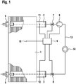
- FIG. 1 shows schematically an embodiment of a device proposed here.
- a heat exchanger 1 with an inlet 2 (flow) for heat transfer medium and an outlet 3 (return) is part of a heating circuit 13 with heating devices 14.
- the heat exchanger 1 is also supplied with a refrigerant, in particular a flammable refrigerant, e.g. B. R290, flows through.
- a refrigerant in particular a flammable refrigerant, e.g. B. R290
- the heat exchanger 1 is provided with additional safety equipment that can be designed in the manner of an STB, only here it is Take measures at too low a temperature instead of at too high a temperature.
- the heat exchanger 1 can be equipped with a thermostatic valve 4 in the area of the inlet 2 and / or with a thermostatic valve in the area of the outlet 3.
- a thermostatic valve is understood here to be a mechanical valve which, due to the deformation or shrinkage of a component, triggers with falling temperature at a certain temperature and shuts off the inlet 2 or outlet 3 or heating circuit 13 at any other point in heat exchanger 1.
- Such a thermostatic valve should preferably only be able to be opened again manually.
- the heat exchanger 1 can also be equipped with one or more temperature sensors 10, 11, 12, which are connected to a central control 9 and whose measured values are monitored for falling below a predefinable threshold temperature. If the temperature falls below one If the temperature sensor 10, 11, 12 is the threshold temperature, the heating circuit 13 is shut off, preferably by closing a valve 7, 8 in inlet 2 and / or in outlet 3 or by switching off a circulating pump 6. A first temperature sensor 11 in the area of the inlet is preferred 2 and a second temperature sensor 12 arranged in the area of the outlet 3, so that the lower measured temperature can be used as a criterion for blocking the heating circuit 13 by at least one of the blocking means 6, 7, 8.
- the invention ensures that no refrigerant can get into a heating circuit through a possible leak after a heat exchanger has frozen.
Landscapes
- Engineering & Computer Science (AREA)
- Physics & Mathematics (AREA)
- Thermal Sciences (AREA)
- Chemical & Material Sciences (AREA)
- Combustion & Propulsion (AREA)
- Mechanical Engineering (AREA)
- General Engineering & Computer Science (AREA)
- Heat-Exchange Devices With Radiators And Conduit Assemblies (AREA)
Applications Claiming Priority (1)
| Application Number | Priority Date | Filing Date | Title |
|---|---|---|---|
| DE102019121569.2A DE102019121569A1 (de) | 2019-08-09 | 2019-08-09 | Schutz gegen Übertritt von Kältemittel in einen Heizkreislauf nach Schäden durch Gefrieren von Wärmeträgermedium in einem Wärmeübertrager |
Publications (3)
| Publication Number | Publication Date |
|---|---|
| EP3772622A1 true EP3772622A1 (fr) | 2021-02-10 |
| EP3772622B1 EP3772622B1 (fr) | 2024-01-24 |
| EP3772622C0 EP3772622C0 (fr) | 2024-01-24 |
Family
ID=71574954
Family Applications (1)
| Application Number | Title | Priority Date | Filing Date |
|---|---|---|---|
| EP20184851.2A Active EP3772622B1 (fr) | 2019-08-09 | 2020-07-09 | Protection contre le transfert de réfrigérant dans un circuit de chauffage après des dommages par congélation de fluide caloporteur dans un échangeur de chaleur |
Country Status (2)
| Country | Link |
|---|---|
| EP (1) | EP3772622B1 (fr) |
| DE (1) | DE102019121569A1 (fr) |
Cited By (1)
| Publication number | Priority date | Publication date | Assignee | Title |
|---|---|---|---|---|
| EP4696953A1 (fr) | 2024-08-08 | 2026-02-18 | Glen Dimplex Deutschland GmbH | Installation de réfrigérant et procédé de fonctionnement d'une installation de réfrigérant |
Citations (3)
| Publication number | Priority date | Publication date | Assignee | Title |
|---|---|---|---|---|
| JP2003240343A (ja) * | 2002-02-12 | 2003-08-27 | Denso Corp | 熱交換装置及び給湯装置 |
| EP2149758A1 (fr) * | 2008-07-30 | 2010-02-03 | Novotherm | Procédé de mise hors gel d'un système de production de chaleur et installation de production de chaleur associée |
| US20120273184A1 (en) | 2011-04-27 | 2012-11-01 | Sung Ji Air-Conditioning Technology Co., Ltd. | Freezing protection system of heat exchanger and method for controlling the same |
-
2019
- 2019-08-09 DE DE102019121569.2A patent/DE102019121569A1/de not_active Withdrawn
-
2020
- 2020-07-09 EP EP20184851.2A patent/EP3772622B1/fr active Active
Patent Citations (3)
| Publication number | Priority date | Publication date | Assignee | Title |
|---|---|---|---|---|
| JP2003240343A (ja) * | 2002-02-12 | 2003-08-27 | Denso Corp | 熱交換装置及び給湯装置 |
| EP2149758A1 (fr) * | 2008-07-30 | 2010-02-03 | Novotherm | Procédé de mise hors gel d'un système de production de chaleur et installation de production de chaleur associée |
| US20120273184A1 (en) | 2011-04-27 | 2012-11-01 | Sung Ji Air-Conditioning Technology Co., Ltd. | Freezing protection system of heat exchanger and method for controlling the same |
Cited By (1)
| Publication number | Priority date | Publication date | Assignee | Title |
|---|---|---|---|---|
| EP4696953A1 (fr) | 2024-08-08 | 2026-02-18 | Glen Dimplex Deutschland GmbH | Installation de réfrigérant et procédé de fonctionnement d'une installation de réfrigérant |
Also Published As
| Publication number | Publication date |
|---|---|
| DE102019121569A1 (de) | 2021-02-11 |
| EP3772622B1 (fr) | 2024-01-24 |
| EP3772622C0 (fr) | 2024-01-24 |
Similar Documents
| Publication | Publication Date | Title |
|---|---|---|
| DE102016123330B4 (de) | Laservorrichtung mit Funktion zur Verhinderung einer Kondensation | |
| DE3247302C2 (fr) | ||
| EP3511695A1 (fr) | Chambre d'essai | |
| EP3767186B1 (fr) | Procédé de commande d'une unité extérieure d'une pompe à chaleur | |
| DE102006023498B4 (de) | Zapfluftzufuhrsystem eines Flugzeuges mit einer Schaltanordnung zum Schutz des Zapfluftzufuhrsystems vor Überhitzung | |
| EP2476963A2 (fr) | Procédé de remplissage et de recharge d'eau dans un circuit d'eau | |
| DE102022131726A1 (de) | Wärmepumpensystem mit Gasabscheider | |
| EP3789686A1 (fr) | Système de pompe à chaleur | |
| EP3037741B1 (fr) | Procede destine a eviter le fonctionnement sans eau de chauffe-eau instantane' | |
| DE102007041766B4 (de) | Leckageüberwachung von Anlagen mit mindestens zwei Medienkreisläufen, insbesondere Wärmeübertragern | |
| EP3772622B1 (fr) | Protection contre le transfert de réfrigérant dans un circuit de chauffage après des dommages par congélation de fluide caloporteur dans un échangeur de chaleur | |
| EP3182813A1 (fr) | Système de refroidissement d'onduleur | |
| DE102013101104A1 (de) | Kühlanordnung zum Kühlen eines Objekts mit einer Kontrolleinrichtung und Verfahren zur Überwachung einer solchen Kühlanordnung | |
| EP3767187B1 (fr) | Procédé de commande d'un ensemble de pompes à chaleur | |
| EP4336108B1 (fr) | Séparation de réfrigérant dans un circuit de chauffage | |
| EP4379267A1 (fr) | Système de pompe à chaleur avec séparateur de gaz | |
| DE19749279C2 (de) | Absperrvorrichtung für eine Rohrleitung | |
| DE102020211866A1 (de) | Versorgungssystem zum Bereitstellen eines Wasserstroms und Schutzverfahren zum Betrieb eines Versorgungssystems | |
| EP2447803B1 (fr) | Commande de chauffage | |
| DE212021000319U1 (de) | Ein pneumatischer Aktuator zum intelligenten Brandschutz für ein Ventil | |
| EP1645822A2 (fr) | Procedé et unité d'interface pour l'alimentation et l'évacuation d'un réfrigérant vers ou à partir d'une unité de consommation | |
| AT413595B (de) | Verfahren zum betrieb einer wärmeversorgungseinheit | |
| DE19620601C2 (de) | Wärmeübergabestation mit Sicherheitseinrichtung | |
| DE19800882A1 (de) | Wärmeübertragungssystem und Verfahren zum Betrieb desselben | |
| EP4571212A1 (fr) | Pompe à chaleur à l'intérieur, procédé de fonctionnement d'une pompe à chaleur à l'intérieur et unité de commande pour une telle pompe |
Legal Events
| Date | Code | Title | Description |
|---|---|---|---|
| PUAI | Public reference made under article 153(3) epc to a published international application that has entered the european phase |
Free format text: ORIGINAL CODE: 0009012 |
|
| STAA | Information on the status of an ep patent application or granted ep patent |
Free format text: STATUS: THE APPLICATION HAS BEEN PUBLISHED |
|
| AK | Designated contracting states |
Kind code of ref document: A1 Designated state(s): AL AT BE BG CH CY CZ DE DK EE ES FI FR GB GR HR HU IE IS IT LI LT LU LV MC MK MT NL NO PL PT RO RS SE SI SK SM TR |
|
| AX | Request for extension of the european patent |
Extension state: BA ME |
|
| STAA | Information on the status of an ep patent application or granted ep patent |
Free format text: STATUS: REQUEST FOR EXAMINATION WAS MADE |
|
| 17P | Request for examination filed |
Effective date: 20210809 |
|
| RBV | Designated contracting states (corrected) |
Designated state(s): AL AT BE BG CH CY CZ DE DK EE ES FI FR GB GR HR HU IE IS IT LI LT LU LV MC MK MT NL NO PL PT RO RS SE SI SK SM TR |
|
| STAA | Information on the status of an ep patent application or granted ep patent |
Free format text: STATUS: EXAMINATION IS IN PROGRESS |
|
| 17Q | First examination report despatched |
Effective date: 20230130 |
|
| GRAP | Despatch of communication of intention to grant a patent |
Free format text: ORIGINAL CODE: EPIDOSNIGR1 |
|
| STAA | Information on the status of an ep patent application or granted ep patent |
Free format text: STATUS: GRANT OF PATENT IS INTENDED |
|
| RIC1 | Information provided on ipc code assigned before grant |
Ipc: F25B 49/00 20060101ALI20230905BHEP Ipc: F25B 30/02 20060101ALI20230905BHEP Ipc: F28B 9/00 20060101ALI20230905BHEP Ipc: F24F 11/41 20180101ALI20230905BHEP Ipc: F25B 25/00 20060101ALI20230905BHEP Ipc: F24D 19/10 20060101ALI20230905BHEP Ipc: F24D 19/00 20060101ALI20230905BHEP Ipc: F24D 3/18 20060101AFI20230905BHEP |
|
| INTG | Intention to grant announced |
Effective date: 20230926 |
|
| GRAS | Grant fee paid |
Free format text: ORIGINAL CODE: EPIDOSNIGR3 |
|
| GRAA | (expected) grant |
Free format text: ORIGINAL CODE: 0009210 |
|
| STAA | Information on the status of an ep patent application or granted ep patent |
Free format text: STATUS: THE PATENT HAS BEEN GRANTED |
|
| AK | Designated contracting states |
Kind code of ref document: B1 Designated state(s): AL AT BE BG CH CY CZ DE DK EE ES FI FR GB GR HR HU IE IS IT LI LT LU LV MC MK MT NL NO PL PT RO RS SE SI SK SM TR |
|
| REG | Reference to a national code |
Ref country code: GB Ref legal event code: FG4D Free format text: NOT ENGLISH |
|
| REG | Reference to a national code |
Ref country code: CH Ref legal event code: EP |
|
| REG | Reference to a national code |
Ref country code: IE Ref legal event code: FG4D Free format text: LANGUAGE OF EP DOCUMENT: GERMAN |
|
| REG | Reference to a national code |
Ref country code: DE Ref legal event code: R096 Ref document number: 502020006804 Country of ref document: DE |
|
| U01 | Request for unitary effect filed |
Effective date: 20240219 |
|
| U07 | Unitary effect registered |
Designated state(s): AT BE BG DE DK EE FI FR IT LT LU LV MT NL PT SE SI Effective date: 20240223 |
|
| PG25 | Lapsed in a contracting state [announced via postgrant information from national office to epo] |
Ref country code: IS Free format text: LAPSE BECAUSE OF FAILURE TO SUBMIT A TRANSLATION OF THE DESCRIPTION OR TO PAY THE FEE WITHIN THE PRESCRIBED TIME-LIMIT Effective date: 20240524 |
|
| PG25 | Lapsed in a contracting state [announced via postgrant information from national office to epo] |
Ref country code: GR Free format text: LAPSE BECAUSE OF FAILURE TO SUBMIT A TRANSLATION OF THE DESCRIPTION OR TO PAY THE FEE WITHIN THE PRESCRIBED TIME-LIMIT Effective date: 20240425 |
|
| PG25 | Lapsed in a contracting state [announced via postgrant information from national office to epo] |
Ref country code: HR Free format text: LAPSE BECAUSE OF FAILURE TO SUBMIT A TRANSLATION OF THE DESCRIPTION OR TO PAY THE FEE WITHIN THE PRESCRIBED TIME-LIMIT Effective date: 20240124 Ref country code: RS Free format text: LAPSE BECAUSE OF FAILURE TO SUBMIT A TRANSLATION OF THE DESCRIPTION OR TO PAY THE FEE WITHIN THE PRESCRIBED TIME-LIMIT Effective date: 20240424 |
|
| PG25 | Lapsed in a contracting state [announced via postgrant information from national office to epo] |
Ref country code: ES Free format text: LAPSE BECAUSE OF FAILURE TO SUBMIT A TRANSLATION OF THE DESCRIPTION OR TO PAY THE FEE WITHIN THE PRESCRIBED TIME-LIMIT Effective date: 20240124 |
|
| PG25 | Lapsed in a contracting state [announced via postgrant information from national office to epo] |
Ref country code: RS Free format text: LAPSE BECAUSE OF FAILURE TO SUBMIT A TRANSLATION OF THE DESCRIPTION OR TO PAY THE FEE WITHIN THE PRESCRIBED TIME-LIMIT Effective date: 20240424 Ref country code: NO Free format text: LAPSE BECAUSE OF FAILURE TO SUBMIT A TRANSLATION OF THE DESCRIPTION OR TO PAY THE FEE WITHIN THE PRESCRIBED TIME-LIMIT Effective date: 20240424 Ref country code: IS Free format text: LAPSE BECAUSE OF FAILURE TO SUBMIT A TRANSLATION OF THE DESCRIPTION OR TO PAY THE FEE WITHIN THE PRESCRIBED TIME-LIMIT Effective date: 20240524 Ref country code: HR Free format text: LAPSE BECAUSE OF FAILURE TO SUBMIT A TRANSLATION OF THE DESCRIPTION OR TO PAY THE FEE WITHIN THE PRESCRIBED TIME-LIMIT Effective date: 20240124 Ref country code: GR Free format text: LAPSE BECAUSE OF FAILURE TO SUBMIT A TRANSLATION OF THE DESCRIPTION OR TO PAY THE FEE WITHIN THE PRESCRIBED TIME-LIMIT Effective date: 20240425 Ref country code: ES Free format text: LAPSE BECAUSE OF FAILURE TO SUBMIT A TRANSLATION OF THE DESCRIPTION OR TO PAY THE FEE WITHIN THE PRESCRIBED TIME-LIMIT Effective date: 20240124 |
|
| U20 | Renewal fee for the european patent with unitary effect paid |
Year of fee payment: 5 Effective date: 20240627 |
|
| PG25 | Lapsed in a contracting state [announced via postgrant information from national office to epo] |
Ref country code: PL Free format text: LAPSE BECAUSE OF FAILURE TO SUBMIT A TRANSLATION OF THE DESCRIPTION OR TO PAY THE FEE WITHIN THE PRESCRIBED TIME-LIMIT Effective date: 20240124 |
|
| PG25 | Lapsed in a contracting state [announced via postgrant information from national office to epo] |
Ref country code: PL Free format text: LAPSE BECAUSE OF FAILURE TO SUBMIT A TRANSLATION OF THE DESCRIPTION OR TO PAY THE FEE WITHIN THE PRESCRIBED TIME-LIMIT Effective date: 20240124 |
|
| PG25 | Lapsed in a contracting state [announced via postgrant information from national office to epo] |
Ref country code: SM Free format text: LAPSE BECAUSE OF FAILURE TO SUBMIT A TRANSLATION OF THE DESCRIPTION OR TO PAY THE FEE WITHIN THE PRESCRIBED TIME-LIMIT Effective date: 20240124 |
|
| PG25 | Lapsed in a contracting state [announced via postgrant information from national office to epo] |
Ref country code: CZ Free format text: LAPSE BECAUSE OF FAILURE TO SUBMIT A TRANSLATION OF THE DESCRIPTION OR TO PAY THE FEE WITHIN THE PRESCRIBED TIME-LIMIT Effective date: 20240124 |
|
| REG | Reference to a national code |
Ref country code: DE Ref legal event code: R097 Ref document number: 502020006804 Country of ref document: DE |
|
| PG25 | Lapsed in a contracting state [announced via postgrant information from national office to epo] |
Ref country code: SK Free format text: LAPSE BECAUSE OF FAILURE TO SUBMIT A TRANSLATION OF THE DESCRIPTION OR TO PAY THE FEE WITHIN THE PRESCRIBED TIME-LIMIT Effective date: 20240124 |
|
| PG25 | Lapsed in a contracting state [announced via postgrant information from national office to epo] |
Ref country code: SM Free format text: LAPSE BECAUSE OF FAILURE TO SUBMIT A TRANSLATION OF THE DESCRIPTION OR TO PAY THE FEE WITHIN THE PRESCRIBED TIME-LIMIT Effective date: 20240124 Ref country code: SK Free format text: LAPSE BECAUSE OF FAILURE TO SUBMIT A TRANSLATION OF THE DESCRIPTION OR TO PAY THE FEE WITHIN THE PRESCRIBED TIME-LIMIT Effective date: 20240124 Ref country code: CZ Free format text: LAPSE BECAUSE OF FAILURE TO SUBMIT A TRANSLATION OF THE DESCRIPTION OR TO PAY THE FEE WITHIN THE PRESCRIBED TIME-LIMIT Effective date: 20240124 |
|
| PLBE | No opposition filed within time limit |
Free format text: ORIGINAL CODE: 0009261 |
|
| STAA | Information on the status of an ep patent application or granted ep patent |
Free format text: STATUS: NO OPPOSITION FILED WITHIN TIME LIMIT |
|
| 26N | No opposition filed |
Effective date: 20241025 |
|
| PG25 | Lapsed in a contracting state [announced via postgrant information from national office to epo] |
Ref country code: MC Free format text: LAPSE BECAUSE OF FAILURE TO SUBMIT A TRANSLATION OF THE DESCRIPTION OR TO PAY THE FEE WITHIN THE PRESCRIBED TIME-LIMIT Effective date: 20240124 |
|
| REG | Reference to a national code |
Ref country code: CH Ref legal event code: PL |
|
| PG25 | Lapsed in a contracting state [announced via postgrant information from national office to epo] |
Ref country code: CH Free format text: LAPSE BECAUSE OF NON-PAYMENT OF DUE FEES Effective date: 20240731 |
|
| PGFP | Annual fee paid to national office [announced via postgrant information from national office to epo] |
Ref country code: GB Payment date: 20250625 Year of fee payment: 6 |
|
| PG25 | Lapsed in a contracting state [announced via postgrant information from national office to epo] |
Ref country code: IE Free format text: LAPSE BECAUSE OF NON-PAYMENT OF DUE FEES Effective date: 20240709 |
|
| U20 | Renewal fee for the european patent with unitary effect paid |
Year of fee payment: 6 Effective date: 20250626 |
|
| PG25 | Lapsed in a contracting state [announced via postgrant information from national office to epo] |
Ref country code: RO Free format text: LAPSE BECAUSE OF FAILURE TO SUBMIT A TRANSLATION OF THE DESCRIPTION OR TO PAY THE FEE WITHIN THE PRESCRIBED TIME-LIMIT Effective date: 20240124 |
|
| PG25 | Lapsed in a contracting state [announced via postgrant information from national office to epo] |
Ref country code: CY Free format text: LAPSE BECAUSE OF FAILURE TO SUBMIT A TRANSLATION OF THE DESCRIPTION OR TO PAY THE FEE WITHIN THE PRESCRIBED TIME-LIMIT; INVALID AB INITIO Effective date: 20200709 |
|
| PG25 | Lapsed in a contracting state [announced via postgrant information from national office to epo] |
Ref country code: HU Free format text: LAPSE BECAUSE OF FAILURE TO SUBMIT A TRANSLATION OF THE DESCRIPTION OR TO PAY THE FEE WITHIN THE PRESCRIBED TIME-LIMIT; INVALID AB INITIO Effective date: 20200709 |