EP3772611A1 - Système de réalisation d'un luminaire doté d'un préhenseur électrique avec porte-conducteur - Google Patents
Système de réalisation d'un luminaire doté d'un préhenseur électrique avec porte-conducteur Download PDFInfo
- Publication number
- EP3772611A1 EP3772611A1 EP20189844.2A EP20189844A EP3772611A1 EP 3772611 A1 EP3772611 A1 EP 3772611A1 EP 20189844 A EP20189844 A EP 20189844A EP 3772611 A1 EP3772611 A1 EP 3772611A1
- Authority
- EP
- European Patent Office
- Prior art keywords
- section
- longitudinal direction
- holding
- contact
- sections
- Prior art date
- Legal status (The legal status is an assumption and is not a legal conclusion. Google has not performed a legal analysis and makes no representation as to the accuracy of the status listed.)
- Granted
Links
Images
Classifications
-
- F—MECHANICAL ENGINEERING; LIGHTING; HEATING; WEAPONS; BLASTING
- F21—LIGHTING
- F21V—FUNCTIONAL FEATURES OR DETAILS OF LIGHTING DEVICES OR SYSTEMS THEREOF; STRUCTURAL COMBINATIONS OF LIGHTING DEVICES WITH OTHER ARTICLES, NOT OTHERWISE PROVIDED FOR
- F21V21/00—Supporting, suspending, or attaching arrangements for lighting devices; Hand grips
- F21V21/34—Supporting elements displaceable along a guiding element
- F21V21/35—Supporting elements displaceable along a guiding element with direct electrical contact between the supporting element and electric conductors running along the guiding element
-
- F—MECHANICAL ENGINEERING; LIGHTING; HEATING; WEAPONS; BLASTING
- F21—LIGHTING
- F21S—NON-PORTABLE LIGHTING DEVICES; SYSTEMS THEREOF; VEHICLE LIGHTING DEVICES SPECIALLY ADAPTED FOR VEHICLE EXTERIORS
- F21S8/00—Lighting devices intended for fixed installation
- F21S8/04—Lighting devices intended for fixed installation intended only for mounting on a ceiling or the like overhead structures
-
- F—MECHANICAL ENGINEERING; LIGHTING; HEATING; WEAPONS; BLASTING
- F21—LIGHTING
- F21V—FUNCTIONAL FEATURES OR DETAILS OF LIGHTING DEVICES OR SYSTEMS THEREOF; STRUCTURAL COMBINATIONS OF LIGHTING DEVICES WITH OTHER ARTICLES, NOT OTHERWISE PROVIDED FOR
- F21V21/00—Supporting, suspending, or attaching arrangements for lighting devices; Hand grips
- F21V21/002—Supporting, suspending, or attaching arrangements for lighting devices; Hand grips making direct electrical contact, e.g. by piercing
-
- F—MECHANICAL ENGINEERING; LIGHTING; HEATING; WEAPONS; BLASTING
- F21—LIGHTING
- F21V—FUNCTIONAL FEATURES OR DETAILS OF LIGHTING DEVICES OR SYSTEMS THEREOF; STRUCTURAL COMBINATIONS OF LIGHTING DEVICES WITH OTHER ARTICLES, NOT OTHERWISE PROVIDED FOR
- F21V21/00—Supporting, suspending, or attaching arrangements for lighting devices; Hand grips
- F21V21/02—Wall, ceiling, or floor bases; Fixing pendants or arms to the bases
- F21V21/025—Elongated bases having a U-shaped cross section
-
- F—MECHANICAL ENGINEERING; LIGHTING; HEATING; WEAPONS; BLASTING
- F21—LIGHTING
- F21V—FUNCTIONAL FEATURES OR DETAILS OF LIGHTING DEVICES OR SYSTEMS THEREOF; STRUCTURAL COMBINATIONS OF LIGHTING DEVICES WITH OTHER ARTICLES, NOT OTHERWISE PROVIDED FOR
- F21V23/00—Arrangement of electric circuit elements in or on lighting devices
- F21V23/001—Arrangement of electric circuit elements in or on lighting devices the elements being electrical wires or cables
-
- F—MECHANICAL ENGINEERING; LIGHTING; HEATING; WEAPONS; BLASTING
- F21—LIGHTING
- F21V—FUNCTIONAL FEATURES OR DETAILS OF LIGHTING DEVICES OR SYSTEMS THEREOF; STRUCTURAL COMBINATIONS OF LIGHTING DEVICES WITH OTHER ARTICLES, NOT OTHERWISE PROVIDED FOR
- F21V23/00—Arrangement of electric circuit elements in or on lighting devices
- F21V23/06—Arrangement of electric circuit elements in or on lighting devices the elements being coupling devices, e.g. connectors
-
- H—ELECTRICITY
- H01—ELECTRIC ELEMENTS
- H01R—ELECTRICALLY-CONDUCTIVE CONNECTIONS; STRUCTURAL ASSOCIATIONS OF A PLURALITY OF MUTUALLY-INSULATED ELECTRICAL CONNECTING ELEMENTS; COUPLING DEVICES; CURRENT COLLECTORS
- H01R25/00—Coupling parts adapted for simultaneous co-operation with two or more identical counterparts, e.g. for distributing energy to two or more circuits
- H01R25/14—Rails or bus-bars constructed so that the counterparts can be connected thereto at any point along their length
- H01R25/142—Their counterparts
Definitions
- the invention relates to a system for realizing a lamp according to the preamble of claim 1.
- Systems of the generic type have, as two basic components, a support rail which is elongated in a longitudinal direction and a mounting body which is elongated in the longitudinal direction.
- Supply lines are usually arranged on the mounting rail, and a light source and / or other functional element is usually arranged on the mounting body, such as radio modules, operating devices, etc.
- the mounting rail is used to fix the luminaire to a component, for example a ceiling.
- the mounting rail When installing a lamp, the mounting rail is usually first attached to the component and then the mounting body, which is equipped with the elements or components of the lamp that require a corresponding electrical supply, is fixed on the mounting rail so that the mounting rail and mounting body have one Form interior space in which essential elements, in particular functional elements of the luminaire are arranged, for example circuit boards with LEDs, operating devices, radio modules, supply lines, etc.
- the respective lighting means can also be arranged or fastened like an LED circuit board on the underside of the assembly body.
- the mounting rail and mounting body are each designed to be elongated in a longitudinal direction.
- the support rail usually has a cross section perpendicular to the longitudinal direction, which is open at a vertical end along a vertical direction and is delimited along a transverse direction by two side walls which are connected to one another by a bottom section of the support rail running along the transverse direction.
- the support rail is attached to a component via its base section.
- the mounting body is usually arranged at the open vertical end of the mounting rail, so that the mounting body, together with the mounting rail, forms an interior space which is closed off circumferentially by the mounting rail and the mounting body perpendicular to the longitudinal direction, whereby the enclosure of the interior space can of course be interrupted in sections, for example, to allow an air supply.
- a generic system usually comprises a power conducting rail which is elongated in the longitudinal direction and has channels in which conductor wires are arranged, as well as an electrical contact device with a mounting section and a contact section spaced from the mounting section along a vertical direction and with a transverse direction (Y) perpendicular to the longitudinal direction and side wall sections spaced apart from one another perpendicular to the vertical direction.
- these side wall sections can comprise areas of the mounting section and also areas of the contact section of the contact device.
- the two basic components are attached to each other, wherein the conductor rail is attached to a first of the two basic components and the contact device is attached with its mounting section to a second of the two basic components and with its contact section with at least some of the lead wires are electrically connected.
- the conductor rail is usually attached to the support rail, in particular to the base section of the support rail.
- the conductor rail is fastened to the assembly body in the operating position.
- the basic principle of the conductor rail is to enable contacting across a longitudinal section so that contact can be made between the supply lines arranged on the support rail and the components arranged on the assembly body within a specific longitudinal section and not just at a singular longitudinal position.
- the mounting section of the contact device can be fixed in position on the support rail in the operating position and the contact device can be connected in an electrically conductive manner to electrical supply lines arranged on the support rail, while the power guide rail is arranged on the mounting body and the contact section of the contact device engages in channels of the power guide rail and contacted the conductor wires arranged in the channels, which in turn are connected to components arranged on the mounting body for supplying the components.
- the conductor rail in the operating position of the components of the system for realizing a lamp, can be arranged on the support rail, with the conductor wires arranged in the channels of the conductor rail form at least one section of supply lines that are arranged in the support rail, the mounting section of the contact device being fixed to the mounting body and the contact section of the contact device engaging in the channels of the power conductor rail arranged on the support rail for contacting the arranged therein lead wires, and wherein the contact device is at the same time electrically conductively connected to components which are arranged on the mounting body for supplying these components.
- the contact device thus in principle enables the supply of components arranged on the mounting body by enabling an electrical connection between the supply lines arranged on the support rail and the components.
- these supply lines can also include control or data lines. It must be taken into account that, in order to reach the operating position, the mounting body and the mounting rail are moved towards one another along a vertical direction that is perpendicular to the longitudinal direction until they are arranged and fixed to one another.
- Common retaining springs are known to those skilled in the art, by means of which a mounting body can be fixed relative to a mounting rail.
- such retaining springs have a base section for mounting on the assembly body and, at both transverse ends of the base section, a retaining section extending vertically away from the base section, on which a retaining projection is provided that extends outward in the transverse direction.
- This retaining projection typically engages behind a fastening projection which is arranged on one of the side walls of the support rail assigned to the retaining projection.
- a fastening projection which is arranged on one of the side walls of the support rail assigned to the retaining projection.
- this is the assembly body itself designed so that it has a cross-section perpendicular to the longitudinal direction in the manner of a U-shape and thus comprises a bottom section and two side wall sections, the bottom section of the retaining spring often being attached to the mounting body by clamping the bottom section to projections which are attached to the Side wall portions of the mounting body are provided, whereby the bottom portion of the retaining spring is pressed against the bottom portion of the mounting body.
- other fastening options are also known, for example by means of screwing, latching or by means of bayonet locks, by means of which a mounting body can be fixed to the mounting rail.
- suitable fastening means with which the assembly body is fastened to the mounting rail in the operating position, are preferably used to prevent the mounting body
- a large number of common contact devices are known in the prior art, via which the contact between the mounting body and the mounting rail or between components arranged on the mounting body and supply lines arranged on the mounting rail is possible by means of a conductor rail.
- the contact devices are often designed in such a way that they have contact sections with which they can be introduced into the ducts of the conductor rail. For example, it is known to attach a fixed tap to a conductor rail that contacts the conductor wires arranged in the channels of the conductor rail, this tap forming the contact section of the contact device and being connected to a mounting section via a respective cable, with the conductor rail and the mounting section at different Basic components are attached.
- contact devices that are to be attached to one of the two basic components with their mounting section, the power conducting rail is attached to the other of the two basic components and the contact device has such electrical contact sections that when the mounting body and support rail are vertically brought together, the contact sections in the ducts of the conductor rail are introduced and contact the conductor wires arranged therein.
- the system has further lines that extend in the longitudinal direction and are therefore attached to one of the components of the luminaire .
- This lighting wiring can be done, for example, underneath the contact device between the contact device and the mounting body, as it is for example in the European patent application EP 2 365 597 B1 is described. This teaches the provision of wire holders which are fastened to a mounting plate and are sufficiently secured against rotation so that manual or automatic assembly by means of a robot is made possible.
- the wire holders described in the prior art require a further work step by fastening the respective wire holder to the mounting plate, which increases the effort involved in assembling the lamp.
- a lateral arrangement of the wiring on the contact device on the other hand, there is the risk of lines being squeezed and thereby damaged when the operating position of the components is set, in particular the fixing of the mounting body on the mounting rail.
- the lines can inadvertently intervene in undercuts or recesses of the components or interfere with projections of the components, so that an assembly of the system and thus the setting of the operating position of the components is prevented.
- the present invention is based on the object of modifying a generic system for realizing a lamp so that the assembly of the system is simplified.
- the system according to the invention has a power guide rail which is elongated in the longitudinal direction and on which conductor wires are arranged, wherein the power conductor rail can have channels in which the conductor wires can be arranged, and has an electrical contact device with a mounting section and a contact portion offset in a vertical direction to the mounting portion.
- the electrical contact device also has in a transverse direction that is perpendicular to In the longitudinal direction and perpendicular to the vertical direction, spaced-apart sidewall sections which, depending on the embodiment, can include both areas of the mounting section and areas of the contact section.
- these side wall sections do not have to be flat and continuous, but can generally mean lateral delimiting structures of the contact device in the manner of a side section.
- the two basic components support rail and mounting body are attached to one another, and the mounting section and the contact section of the contact device are also attached to one another.
- the mounting section and the contact section of the contact device can be designed as two separate components which are combined with one another to form a cohesively fixed component, but they can also be designed together as a single-piece component.
- the conductor rail In its operating position, the conductor rail is fastened to a first of the basic components, and in the operating position the contact device is fastened with its mounting section to a second of the two basic components and its contact section is electrically conductively connected to at least some of the conductor wires of the conductor rail.
- the conductor rail is fixed on the mounting rail and the mounting section of the contact device is fixed, ie fastened, to the mounting body.
- the mounting body and the mounting rail are particularly preferably fastened to one another by fastening means which permit a relative movement of the mounting body along the vertical direction from the Prevent mounting rail away.
- the mounting body and the support rail are designed to correspond to one another so that they are guided to one another along the vertical direction to reach the operating position until they reach a vertical end position, in which case they are fixed to one another by fastening means in this vertical end position.
- the second base component can have a base section and two side wall sections extending away from the base section along the vertical direction, the mounting section of the contact device being held pressed against the base section on the second base component, in particular on the mounting body, in the operating position.
- the contact device has a conductor holding device on at least one of its lateral sections or side wall sections spaced apart in the transverse direction, comprising at least two holding brackets spaced apart in the longitudinal direction and each provided with a gap in the vertical direction, which can also be referred to as an interruption, the interruptions being the holding brackets are spaced apart from one another in the vertical direction and the retaining brackets for holding and / or gripping around lines running in the longitudinal direction, which can also be referred to here as conductors and in particular can also have insulation, in particular in the manner of a sheathing.
- the specified retaining clips on the at least one side wall section of the contact device have a predetermined extension in the longitudinal direction, so that such a retaining clip is also referred to below as a retaining clip section or a retaining clip longitudinal section.
- a retaining bracket can also have further gaps / interruptions in addition to the specified interruption in the vertical direction.
- the system according to the invention can have at least one or more further features which are specified above in connection with the description of generic systems.
- the system according to the invention has, on the one hand, the advantage over conventional systems that the contact device has a conductor holding device in the region of at least one of its sides or side sections, which is in particular formed integrally with a section of the contact device, regardless of whether the contact device itself is on or off Is formed in several parts, so that the attachment of wire holders to the mounting body or the mounting plate described in the prior art can be omitted.
- a respective longitudinal conductor can first be inserted into the conductor holding device of the contact device provided according to the invention and then the mounting body with the contact device attached to it by vertical Moving towards one another are connected to the mounting rail of the system without there being a risk that parts of the mounting rail protruding inward in the transverse direction will engage in one of the interruptions in the retaining bracket and thus prevent the operating position from being reached, since the gaps or interruptions in the longitudinally spaced apart Retaining bracket or retaining bracket longitudinal sections are shifted in the vertical direction to one another.
- a plurality of retaining brackets such as two retaining brackets can be provided which, in particular in a plane that is spanned by the vertical direction and the longitudinal direction, provide a closed retaining section that is interrupted at a single point in the form of the designated gap, so that in the In the area of these interruptions, the respective conductor can be introduced into the holding section of the respective holding bracket, in particular by means of a robot, so that the respective conductor is securely held and / or encompassed within the holding bracket or holding bracket sections.
- each of the holding brackets or holding bracket longitudinal sections defines a respective holding section in which lines or conductors running in the longitudinal direction are retained or encompassed. It can preferably be provided that a retaining bracket arm section extends essentially in the vertical direction, it being possible for this to be interrupted in the vertical direction by the specified gap or interruption.
- the conductor holding device of the contact device in the invention is not limited to the provision of two longitudinally spaced retaining bracket sections; instead, between the two longitudinally spaced apart retaining bracket sections with a predetermined longitudinal extent, one or more additional retaining brackets each with a predetermined longitudinal extent can be provided, with the gaps of the at least two retaining bracket sections preferably being on one imaginary straight line in a plane spanned by the vertical and the longitudinal direction.
- a predetermined guidance of the line or conductor running in the longitudinal direction is established over the entire longitudinal extent of the contact device; in addition, the manual or automatic introduction of the conductors into the conductor holding device can be carried out relatively through a simple linear movement, in particular a pure longitudinal movement of a robot blade be carried out to the assembly body in order to insert the line or conductor in the at least two retaining bracket sections or retaining bracket.
- the plurality of holding bracket longitudinal sections of the conductor holding device of the contact device follow one another without gaps, so that a continuous holding bracket results in the longitudinal direction, so that the lines or conductors in the longitudinal direction of the contact device over the entire length of the conductor holding device, in particular the contact device , is provided.
- the gap or interruption of the holding bracket which is continuous in the longitudinal direction, corresponds approximately to the robot blade in its vertical extension so that it can penetrate the respective conductor through the opening provided by the gap or interruption can bring in the holding portion of the bracket.
- the robot blade then moves on this straight line, which is again ensured is that no transverse, ie transversal, projections or edges of the mounting rail come into engagement with an interruption or gap in the respective retaining bracket when assembling the mounting body with the contact device attached to it.
- a respective holding bracket in particular all holding brackets that are spaced apart from one another in the longitudinal direction, are designed to be elastically deflectable in sections in the longitudinal direction to enlarge the respective interruption or gap in the vertical direction, so that a conductor can be introduced into the Holding areas of the ladder holding device can be carried out by a pure longitudinal movement of an assigned robot blade, which brings a respective conductor into the holding areas.
- the interruption of a respective holding bracket in its vertical extension in its rest position without applying an elastic deformation force in the longitudinal direction when inserting a line into the respective holding area is smaller than the diameter of the line to be introduced, so that it is in the respective holding area of the respective holding bracket are trapped.
- holding areas formed by the holding brackets or holding bracket longitudinal sections are arranged in alignment with one another in the longitudinal direction.
- these holding areas can be oval or rectangular, for example.
- a respective holding bracket section of the at least two holding brackets or holding bracket longitudinal sections has associated vertical arm sections which are vertically spaced apart to provide the respective interruption, at least one of the vertical arm sections delimiting the holding area for holding lines or conductors running in the longitudinal direction in the transverse direction.
- a respective holding bracket longitudinal section can have two vertical arm sections spaced apart in the vertical direction, the cantilevered vertical extension of one vertical arm section being preferably more than twice, in particular more than 2.5 times, the cantilevered vertical extension of the other vertical arm section.
- one of the cantilevered vertical arm lengths can also have a negligible extent, the term "cantilevered vertical extent of a vertical section of a retaining bracket" being able to mean the vertical length of the arm to define the retaining area in the vertical direction.
- end faces of the vertical arm sections assigned to one another which are to be provided face the respective interruption of a retaining bracket at a distance, are formed approximately parallel to one another and at an acute angle to a plane which is spanned by the longitudinal direction and the transverse direction.
- end face means the sections of the two vertical sections for defining the spacing or gap, which are opposite to define this gap.
- the design of the conductor holding device of the contact device in the system according to the invention can preferably be designed in such a way that an imaginary straight connecting line through the interruptions in the retaining brackets or retaining bracket longitudinal sections has an angle to the longitudinal direction of ⁇ 8 °, in particular ⁇ 10 °, particularly useful ⁇ 13 ° is. It is assumed here that said straight connecting line runs centrally through the respective interruption or gap in the respective retaining bracket or retaining bracket longitudinal section.
- At least one vertical section of a respective holding bracket can be elastically deflected in the longitudinal direction from an operating position to increase the respective spacing of the associated vertical arm sections in the vertical direction.
- Elastic deflection of a vertical section in the longitudinal direction means an elastic bending of the section such that the free end of the vertical section is offset in the longitudinal direction with respect to its rest position, in particular its force-free position.
- both vertical arm sections elastically deformable in the longitudinal direction, so that, for example, a longitudinal guidance of a robot blade can be carried out in such a way that when the conductor or the line is introduced into the holding area, both vertical arm sections or their free ends are elastic in the longitudinal direction , ie deflected in the direction of movement of the robot blade.
- the conductor holding device of the contact device can be designed in such a way that a respective holding bracket or holding bracket longitudinal section is designed such that, starting from a rest position, ie a position in which no longitudinal forces act on a vertical arm section of the holding bracket or Holding bracket longitudinal section act, the vertical interruption is ⁇ 3 mm, whereby by elastic deflection in the longitudinal direction of at least one area of the holding bracket or holding bracket longitudinal section Vertical interruption of the retaining bracket or retaining bracket longitudinal section can be converted into a value> 7 mm, in particular> 9 mm.
- a respective geometric design of the conductor holding device or the retaining bracket and / or a corresponding choice of the material and thus its physical size can be selected to implement this feature, the specified values being achieved without the strength limits of sections of the conductor holding device or retaining bracket can be reached or there is a risk that the material will break.
- a respective holding bracket section For the exact design of a respective holding bracket section, it can be provided that vertical arm sections of the respective holding bracket are connected to an associated side section of the contact device by means of an associated crossbar section, the vertical arm sections, these associated crossbar sections of the respective holding bracket and the side section of the contact device forming the respective holding area of the respective holding bracket or define. As already shown, it can expediently be provided that the holding area is closed in a plane which is spanned by the vertical direction and the transverse direction, except for the specified interruption or gap between the vertical arm sections.
- the contact device can be designed in one piece, including the contact section and the mounting section, or also in several pieces, in particular in two pieces, the mounting section then being provided by a mounting part and the contact section being provided by a contact part, and the two parts being connectable to one another.
- the conductor holding device comprising the at least two retaining clips or retaining clip longitudinal sections, is arranged on the contact part. This embodiment is particularly expedient in those cases in which the contact part is produced as a single injection-molded part from plastic, it being possible for the conductor holding device to be produced integrally with the contact part.
- the assembly part is designed as a bent sheet metal part which is designed to be connected to the assembly body, wherein the assembly body can also be designed as a bent sheet metal part in one embodiment.
- the contact part and the mounting part of the contact device can be brought into engagement with one another in such a way that they are designed to be displaceable relative to one another in the longitudinal direction in an assembly position, with these being fixed to one another in an associated operating position.
- the end section facing the support rail is rounded off in the vertical direction. in particular such that a respective transition area between a transverse web section and the associated vertical arm section of the retaining bracket or retaining bracket longitudinal section is rounded on the outside.
- the side wall section or side section of the contact device, on which the conductor holding device is arranged comprises at its longitudinal ends a respective tab extending in the transverse direction, in which a respective holding bracket or holding bracket longitudinal section is integrally formed.
- the contact section of the contact device has a connecting device on its side wall sections (longitudinal sides) for engaging with an associated connecting device one of the side wall sections of the mounting section of the contact device.
- a connecting device has at least one projection extending in the transverse direction
- the associated connecting device has a flange extending in the transverse direction, which in the operating position engages under the projection to provide a positive fit between the assembly section and the contact section that is effective in the vertical direction.
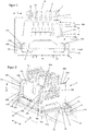
- Figure 1 is a schematic representation of a system designed according to the invention, the cutting plane being perpendicular to the longitudinal direction X, the system and thus all system components being in the operating position.
- the system comprises a mounting rail 1 that can be fastened to a component such as a ceiling and a mounting body 2.
- both the mounting rail 1 and the mounting body 2 have a U-shaped cross-section in a section perpendicular to the longitudinal axis, which is each through a base section and Sidewall sections is formed.
- the operating position shown is the mounting body 2 on the mounting rail 1 by an in Figure 1 Fastening means (not shown), such as a retaining spring, are held in such a way that the mounting body 2 is pressed with its side wall sections 21 along the vertical direction Z against projections formed by the side wall sections of the support rail 1.
- Fastening means such as a retaining spring
- the conductor rail 3 has vertically extending webs which are spaced apart in the transverse direction Y and which form intermediate channels, with conductor wires (not shown here) being arranged in the channels, which are held on the power conductor rail 3 by recesses 310 provided in the webs 31.
- a contact device 4 is attached to the specified operating position, the mounting section 7 of the contact device 4 being pressed in the vertical direction Z against the bottom section 22 of the mounting body 2.
- the contact device 4 has a contact section 5 which is arranged offset from the assembly section 7 along the vertical direction Z.
- the contact section 5 of the contact device 4 has webs 51 which, in the operating position, are arranged in the channels of the conductor rail 3 and press against lead wires of the conductor rail 3, which are arranged in the channels and are held on the webs 31.
- the figure does not show the electrical contact elements which are provided on the webs 51 of the contact section 5 and which press against the lead wires of the conductor rail 3 in the operating position.
- the retaining bracket 58b comprises two spaced-apart vertical arm sections 61a, b, which encompass a predetermined spacing in the vertical direction to provide said gap 62b.
- the retaining bracket 58a is formed integrally with the contact section or the contact part 5 as an injection-molded part, with a small longitudinal extension of the retaining bracket, for example a value between 1.5 mm to 3 mm, see Figure 2 , allows an elastic deflection of the vertical arm sections in the longitudinal direction. This applies in particular to the vertical arm section 61a due to its greater vertical extension than the second vertical arm section 61b.
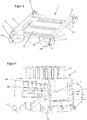
- the relative arrangement of the contact section 5, the mounting section 7 of the contact device 4 and the mounting body 2 is shown in the perspective view Figure 2 emerged.
- the contact section 5 has a section 53 with which it rests on a section 76 of the assembly body 7 and is held pressed against this section 76.
- the assembly body 7 has a spring device 71 which forms a scraper 730 at a transverse end which, in the operating position, presses from below against the projection 210 of a side wall section 21 of the assembly body 2 assigned to the respective scraper 730 and thereby a support section 75 of the Mounting section 7 against presses the bottom portion 22 of the mounting body 2.
- the spring device 71 is shown in its non-deflected rest position in the schematic basic illustrations, which is purely due to the illustration.
- the scraper 730 in the operating position does not extend into the side section 21, as shown in the figures, but rests from below against the projection 210 of the side wall section 21 and thereby presses the support section 75 of the mounting section 7 against the bottom section 22 of the mounting body 2.
- Figure 2 shows in the perspective oblique view the design of the conductor holding device on the contact section or the contact part 5 for receiving lines running in the longitudinal direction X, such as cables etc., these lines not being shown in the figure.
- the contact section 5 has at its longitudinal ends or end faces flanges 57a, b and 57c, d which extend outwardly in the transverse direction from the respective side wall 56a, b.
- the flanges 57a, c extending from the side wall 56a are designed with recesses that act as holding sections 59a, b, so that a respective holding bracket 58a, b is formed, each of which has two vertical arm sections 60a, b and 61a, b, which face one another at a predetermined vertical distance, so that the gap or interruption 62a, b shown in the figures results in the vertical direction.
- the retaining brackets 58a, b which are spaced apart in the longitudinal direction and provided with a predetermined longitudinal extent, are designed such that the two interruptions 62a, b are offset from one another in the vertical direction.
- the respective gap 62a, b has an extension of ⁇ 3 mm, in particular ⁇ 2 mm, in the longitudinal direction, so that conductors or cables held by them are not inadvertently held in the rest position of the holding arms, especially when setting the operating position of all components from the respective holding area fall out.
- the two components ie the contact section 5 and the mounting section 7 of the contact device of the system according to the invention are shown in a respective perspective view.
- the mounting section 7 is designed as a component which is produced from sheet metal by sheet metal forming.
- the mounting section 7 has a sheet metal section 73 formed by the deformation, which is designed as a projection extending inward in the transverse direction.
- the contact device 5 has a complementary section formed by projections 52, which can be brought into engagement with the sheet metal section 73.
- the contact section 5 has an injection-molded body in which both the webs 51 and the projections 52, which form the described counter-section to the sheet metal section 73, are part of the Injection molded body are formed.
- the contact section 5 and the mounting section 7 of the contact device can be fixed to one another in a captive manner by attaching the contact section 5 relative to the mounting section 7 in such a way that the deformed sheet metal section 73 of the mounting body 7 engages around the projections 52 and the contact section 5 with its section 53 against the corresponding section 76 of the mounting body 7 is pressed.
- the mounting section 7 has stops 74 which define a longitudinal area within which the contact section 5 can be displaced in a mounting position relative to the mounting section 7 along the longitudinal direction X. In the operating position of the mounting part and the contact part of the contact device, this displaceability is blocked in the longitudinal direction.
Landscapes
- Engineering & Computer Science (AREA)
- General Engineering & Computer Science (AREA)
- Installation Of Indoor Wiring (AREA)
Applications Claiming Priority (1)
| Application Number | Priority Date | Filing Date | Title |
|---|---|---|---|
| DE102019121165.4A DE102019121165A1 (de) | 2019-08-06 | 2019-08-06 | System zur Realisierung einer Leuchte mit elektrischem Abgriff mit Leiterhalter |
Publications (2)
| Publication Number | Publication Date |
|---|---|
| EP3772611A1 true EP3772611A1 (fr) | 2021-02-10 |
| EP3772611B1 EP3772611B1 (fr) | 2023-07-26 |
Family
ID=71994380
Family Applications (1)
| Application Number | Title | Priority Date | Filing Date |
|---|---|---|---|
| EP20189844.2A Active EP3772611B1 (fr) | 2019-08-06 | 2020-08-06 | Système de réalisation d'un luminaire doté d'un préhenseur électrique avec porte-conducteur |
Country Status (3)
| Country | Link |
|---|---|
| EP (1) | EP3772611B1 (fr) |
| DE (1) | DE102019121165A1 (fr) |
| PL (1) | PL3772611T3 (fr) |
Cited By (2)
| Publication number | Priority date | Publication date | Assignee | Title |
|---|---|---|---|---|
| CN115606058A (zh) * | 2021-04-23 | 2023-01-13 | 赞托贝尔照明有限公司(At) | 用于连接到安装导轨的接触元件 |
| WO2023111293A1 (fr) * | 2021-12-17 | 2023-06-22 | Trilux Gmbh & Co. Kg | Luminaire modulaire à dispositif de contact |
Citations (3)
| Publication number | Priority date | Publication date | Assignee | Title |
|---|---|---|---|---|
| EP1361632A1 (fr) * | 2002-05-08 | 2003-11-12 | Zumtobel Staff GmbH | Elément de support pour contact élastique |
| EP3477792A1 (fr) * | 2017-10-27 | 2019-05-01 | Wago Verwaltungsgesellschaft mbH | Connecteur enfichable de prise et contact de mise à la terre de protection correspondant |
| EP3477791A1 (fr) * | 2017-10-27 | 2019-05-01 | Wago Verwaltungsgesellschaft mbH | Connecteur de dérivation |
Family Cites Families (5)
| Publication number | Priority date | Publication date | Assignee | Title |
|---|---|---|---|---|
| DE8913369U1 (de) * | 1989-11-13 | 1990-01-11 | Kotzolt-Leuchten L. & G. Kotzolt GmbH & Co KG, 4920 Lemgo | Kabelhalter |
| DE202010003420U1 (de) * | 2010-03-10 | 2011-08-04 | Zumtobel Lighting Gmbh | Drahthalter für eine Leuchte |
| CH709008B1 (de) * | 2013-12-18 | 2017-07-14 | Regent Beleuchtungskörper Ag | Halter für eine Betriebskomponente einer Leuchte. |
| DE102017125206A1 (de) * | 2017-10-27 | 2019-05-02 | Siteco Beleuchtungstechnik Gmbh | Montagesystem zum befestigen eines funktionseinsatzes an einer tragschiene eines stromschienensystems, funktionseinsatz und stromschienensystem |
| EP3517833A1 (fr) * | 2018-01-29 | 2019-07-31 | Valeo Iluminacion | Partie d'automobile, procédé et appareil de fabrication d'un dispositif d'éclairage automobile et dispositif d'éclairage automobile |
-
2019
- 2019-08-06 DE DE102019121165.4A patent/DE102019121165A1/de active Pending
-
2020
- 2020-08-06 PL PL20189844.2T patent/PL3772611T3/pl unknown
- 2020-08-06 EP EP20189844.2A patent/EP3772611B1/fr active Active
Patent Citations (3)
| Publication number | Priority date | Publication date | Assignee | Title |
|---|---|---|---|---|
| EP1361632A1 (fr) * | 2002-05-08 | 2003-11-12 | Zumtobel Staff GmbH | Elément de support pour contact élastique |
| EP3477792A1 (fr) * | 2017-10-27 | 2019-05-01 | Wago Verwaltungsgesellschaft mbH | Connecteur enfichable de prise et contact de mise à la terre de protection correspondant |
| EP3477791A1 (fr) * | 2017-10-27 | 2019-05-01 | Wago Verwaltungsgesellschaft mbH | Connecteur de dérivation |
Cited By (2)
| Publication number | Priority date | Publication date | Assignee | Title |
|---|---|---|---|---|
| CN115606058A (zh) * | 2021-04-23 | 2023-01-13 | 赞托贝尔照明有限公司(At) | 用于连接到安装导轨的接触元件 |
| WO2023111293A1 (fr) * | 2021-12-17 | 2023-06-22 | Trilux Gmbh & Co. Kg | Luminaire modulaire à dispositif de contact |
Also Published As
| Publication number | Publication date |
|---|---|
| EP3772611B1 (fr) | 2023-07-26 |
| DE102019121165A1 (de) | 2021-02-11 |
| PL3772611T3 (pl) | 2024-01-22 |
Similar Documents
| Publication | Publication Date | Title |
|---|---|---|
| DE102006031912B4 (de) | Flachkabelklemme | |
| DE102010032383B4 (de) | Stromschienenverbinder und Stromschienensystem mit mindestens zwei benachbarten Stromschienen und einem Stromschienenverbinder | |
| EP2086077A2 (fr) | Système de montage pour composants électriques et/ou mécaniques | |
| DE202008015309U1 (de) | Montagesystem für elektrische und/oder mechanische Komponenten | |
| EP2018684B1 (fr) | Module avec des raccords pour actionneurs et/ou capteurs | |
| DE10339945B4 (de) | Elektrischer Verteilerkasten und Verfahren zum Abschneiden von Drähten | |
| DE102020119312A1 (de) | Länglicher Steckkontakt | |
| EP3644460B1 (fr) | Système de rails conducteurs | |
| EP3772611B1 (fr) | Système de réalisation d'un luminaire doté d'un préhenseur électrique avec porte-conducteur | |
| DE102010040322B4 (de) | Schiebevorrichtung zur Befestigung eines Gehäuses und Installationsgerät mit einer solchen Schiebevorrichtung | |
| DE102018203578B4 (de) | Anordnung zur elektrischen Verbindung von Polterminals sowie Zellmodul oder Batterie mit einer derartigen Verbindungsanordnung (I) | |
| EP3084893A1 (fr) | Bloc de jonction | |
| EP2827051B1 (fr) | Éclairage | |
| EP4002615A1 (fr) | Fixation d'un couplage pour un système de bande lumineuse | |
| EP4430707A1 (fr) | Appareil de support de contact, dispositif de connexion, actionneur, insert de connecteur enfichable et procédé d'installation, et système de connexion de câble | |
| EP3477791B1 (fr) | Connecteur de dérivation | |
| EP3885648B1 (fr) | Système de fourniture d'un luminaire pourvu de branchement électrique comprenant un dispositif contact traversant | |
| DE202011000622U1 (de) | Sammelschienenabgreifklemme | |
| EP4178048A1 (fr) | Luminaire avec profil de support, rail de guidage de courant et connecteur | |
| EP3975349A1 (fr) | Rail porteur allongé et système de rail porteur | |
| EP3772607B1 (fr) | Luminaire à prise d'atténuation | |
| DE102021133811B4 (de) | Kabelkanal für automatisierte Verdrahtung einer elektrischen Steuerungs- oder Schaltanlage | |
| EP3700018B1 (fr) | Dispositif de contact direct pour cartes de circuit imprimé permettant de produire un contact électrique, ainsi que carte de circuit imprimé et appareil électrique | |
| DE102019109656A1 (de) | System zur Realisierung einer Leuchte mit elektrischem Abgriff mit Toleranzausgleich | |
| EP4361499A2 (fr) | Bande lumineuse dotée de composants optimisés pour le démontage |
Legal Events
| Date | Code | Title | Description |
|---|---|---|---|
| PUAI | Public reference made under article 153(3) epc to a published international application that has entered the european phase |
Free format text: ORIGINAL CODE: 0009012 |
|
| STAA | Information on the status of an ep patent application or granted ep patent |
Free format text: STATUS: THE APPLICATION HAS BEEN PUBLISHED |
|
| AK | Designated contracting states |
Kind code of ref document: A1 Designated state(s): AL AT BE BG CH CY CZ DE DK EE ES FI FR GB GR HR HU IE IS IT LI LT LU LV MC MK MT NL NO PL PT RO RS SE SI SK SM TR |
|
| AX | Request for extension of the european patent |
Extension state: BA ME |
|
| STAA | Information on the status of an ep patent application or granted ep patent |
Free format text: STATUS: REQUEST FOR EXAMINATION WAS MADE |
|
| 17P | Request for examination filed |
Effective date: 20210427 |
|
| RBV | Designated contracting states (corrected) |
Designated state(s): AL AT BE BG CH CY CZ DE DK EE ES FI FR GB GR HR HU IE IS IT LI LT LU LV MC MK MT NL NO PL PT RO RS SE SI SK SM TR |
|
| STAA | Information on the status of an ep patent application or granted ep patent |
Free format text: STATUS: EXAMINATION IS IN PROGRESS |
|
| 17Q | First examination report despatched |
Effective date: 20210916 |
|
| GRAP | Despatch of communication of intention to grant a patent |
Free format text: ORIGINAL CODE: EPIDOSNIGR1 |
|
| STAA | Information on the status of an ep patent application or granted ep patent |
Free format text: STATUS: GRANT OF PATENT IS INTENDED |
|
| INTG | Intention to grant announced |
Effective date: 20230222 |
|
| GRAS | Grant fee paid |
Free format text: ORIGINAL CODE: EPIDOSNIGR3 |
|
| GRAA | (expected) grant |
Free format text: ORIGINAL CODE: 0009210 |
|
| STAA | Information on the status of an ep patent application or granted ep patent |
Free format text: STATUS: THE PATENT HAS BEEN GRANTED |
|
| P01 | Opt-out of the competence of the unified patent court (upc) registered |
Effective date: 20230527 |
|
| AK | Designated contracting states |
Kind code of ref document: B1 Designated state(s): AL AT BE BG CH CY CZ DE DK EE ES FI FR GB GR HR HU IE IS IT LI LT LU LV MC MK MT NL NO PL PT RO RS SE SI SK SM TR |
|
| REG | Reference to a national code |
Ref country code: CH Ref legal event code: EP |
|
| REG | Reference to a national code |
Ref country code: DE Ref legal event code: R096 Ref document number: 502020004342 Country of ref document: DE |
|
| REG | Reference to a national code |
Ref country code: IE Ref legal event code: FG4D Free format text: LANGUAGE OF EP DOCUMENT: GERMAN |
|
| REG | Reference to a national code |
Ref country code: LT Ref legal event code: MG9D |
|
| REG | Reference to a national code |
Ref country code: NL Ref legal event code: MP Effective date: 20230726 |
|
| PG25 | Lapsed in a contracting state [announced via postgrant information from national office to epo] |
Ref country code: NL Free format text: LAPSE BECAUSE OF FAILURE TO SUBMIT A TRANSLATION OF THE DESCRIPTION OR TO PAY THE FEE WITHIN THE PRESCRIBED TIME-LIMIT Effective date: 20230726 |
|
| PG25 | Lapsed in a contracting state [announced via postgrant information from national office to epo] |
Ref country code: GR Free format text: LAPSE BECAUSE OF FAILURE TO SUBMIT A TRANSLATION OF THE DESCRIPTION OR TO PAY THE FEE WITHIN THE PRESCRIBED TIME-LIMIT Effective date: 20231027 |
|
| PG25 | Lapsed in a contracting state [announced via postgrant information from national office to epo] |
Ref country code: IS Free format text: LAPSE BECAUSE OF FAILURE TO SUBMIT A TRANSLATION OF THE DESCRIPTION OR TO PAY THE FEE WITHIN THE PRESCRIBED TIME-LIMIT Effective date: 20231126 |
|
| PG25 | Lapsed in a contracting state [announced via postgrant information from national office to epo] |
Ref country code: SE Free format text: LAPSE BECAUSE OF FAILURE TO SUBMIT A TRANSLATION OF THE DESCRIPTION OR TO PAY THE FEE WITHIN THE PRESCRIBED TIME-LIMIT Effective date: 20230726 Ref country code: RS Free format text: LAPSE BECAUSE OF FAILURE TO SUBMIT A TRANSLATION OF THE DESCRIPTION OR TO PAY THE FEE WITHIN THE PRESCRIBED TIME-LIMIT Effective date: 20230726 Ref country code: PT Free format text: LAPSE BECAUSE OF FAILURE TO SUBMIT A TRANSLATION OF THE DESCRIPTION OR TO PAY THE FEE WITHIN THE PRESCRIBED TIME-LIMIT Effective date: 20231127 Ref country code: NO Free format text: LAPSE BECAUSE OF FAILURE TO SUBMIT A TRANSLATION OF THE DESCRIPTION OR TO PAY THE FEE WITHIN THE PRESCRIBED TIME-LIMIT Effective date: 20231026 Ref country code: LV Free format text: LAPSE BECAUSE OF FAILURE TO SUBMIT A TRANSLATION OF THE DESCRIPTION OR TO PAY THE FEE WITHIN THE PRESCRIBED TIME-LIMIT Effective date: 20230726 Ref country code: LT Free format text: LAPSE BECAUSE OF FAILURE TO SUBMIT A TRANSLATION OF THE DESCRIPTION OR TO PAY THE FEE WITHIN THE PRESCRIBED TIME-LIMIT Effective date: 20230726 Ref country code: IS Free format text: LAPSE BECAUSE OF FAILURE TO SUBMIT A TRANSLATION OF THE DESCRIPTION OR TO PAY THE FEE WITHIN THE PRESCRIBED TIME-LIMIT Effective date: 20231126 Ref country code: HR Free format text: LAPSE BECAUSE OF FAILURE TO SUBMIT A TRANSLATION OF THE DESCRIPTION OR TO PAY THE FEE WITHIN THE PRESCRIBED TIME-LIMIT Effective date: 20230726 Ref country code: GR Free format text: LAPSE BECAUSE OF FAILURE TO SUBMIT A TRANSLATION OF THE DESCRIPTION OR TO PAY THE FEE WITHIN THE PRESCRIBED TIME-LIMIT Effective date: 20231027 Ref country code: FI Free format text: LAPSE BECAUSE OF FAILURE TO SUBMIT A TRANSLATION OF THE DESCRIPTION OR TO PAY THE FEE WITHIN THE PRESCRIBED TIME-LIMIT Effective date: 20230726 |
|
| REG | Reference to a national code |
Ref country code: CH Ref legal event code: PL |
|
| PG25 | Lapsed in a contracting state [announced via postgrant information from national office to epo] |
Ref country code: LU Free format text: LAPSE BECAUSE OF NON-PAYMENT OF DUE FEES Effective date: 20230806 |
|
| PG25 | Lapsed in a contracting state [announced via postgrant information from national office to epo] |
Ref country code: ES Free format text: LAPSE BECAUSE OF FAILURE TO SUBMIT A TRANSLATION OF THE DESCRIPTION OR TO PAY THE FEE WITHIN THE PRESCRIBED TIME-LIMIT Effective date: 20230726 |
|
| REG | Reference to a national code |
Ref country code: DE Ref legal event code: R097 Ref document number: 502020004342 Country of ref document: DE |
|
| PG25 | Lapsed in a contracting state [announced via postgrant information from national office to epo] |
Ref country code: SM Free format text: LAPSE BECAUSE OF FAILURE TO SUBMIT A TRANSLATION OF THE DESCRIPTION OR TO PAY THE FEE WITHIN THE PRESCRIBED TIME-LIMIT Effective date: 20230726 Ref country code: RO Free format text: LAPSE BECAUSE OF FAILURE TO SUBMIT A TRANSLATION OF THE DESCRIPTION OR TO PAY THE FEE WITHIN THE PRESCRIBED TIME-LIMIT Effective date: 20230726 Ref country code: LU Free format text: LAPSE BECAUSE OF NON-PAYMENT OF DUE FEES Effective date: 20230806 Ref country code: ES Free format text: LAPSE BECAUSE OF FAILURE TO SUBMIT A TRANSLATION OF THE DESCRIPTION OR TO PAY THE FEE WITHIN THE PRESCRIBED TIME-LIMIT Effective date: 20230726 Ref country code: EE Free format text: LAPSE BECAUSE OF FAILURE TO SUBMIT A TRANSLATION OF THE DESCRIPTION OR TO PAY THE FEE WITHIN THE PRESCRIBED TIME-LIMIT Effective date: 20230726 Ref country code: DK Free format text: LAPSE BECAUSE OF FAILURE TO SUBMIT A TRANSLATION OF THE DESCRIPTION OR TO PAY THE FEE WITHIN THE PRESCRIBED TIME-LIMIT Effective date: 20230726 Ref country code: CZ Free format text: LAPSE BECAUSE OF FAILURE TO SUBMIT A TRANSLATION OF THE DESCRIPTION OR TO PAY THE FEE WITHIN THE PRESCRIBED TIME-LIMIT Effective date: 20230726 Ref country code: CH Free format text: LAPSE BECAUSE OF NON-PAYMENT OF DUE FEES Effective date: 20230831 Ref country code: MC Free format text: LAPSE BECAUSE OF FAILURE TO SUBMIT A TRANSLATION OF THE DESCRIPTION OR TO PAY THE FEE WITHIN THE PRESCRIBED TIME-LIMIT Effective date: 20230726 Ref country code: SK Free format text: LAPSE BECAUSE OF FAILURE TO SUBMIT A TRANSLATION OF THE DESCRIPTION OR TO PAY THE FEE WITHIN THE PRESCRIBED TIME-LIMIT Effective date: 20230726 |
|
| REG | Reference to a national code |
Ref country code: BE Ref legal event code: MM Effective date: 20230831 |
|
| REG | Reference to a national code |
Ref country code: IE Ref legal event code: MM4A |
|
| PG25 | Lapsed in a contracting state [announced via postgrant information from national office to epo] |
Ref country code: IT Free format text: LAPSE BECAUSE OF FAILURE TO SUBMIT A TRANSLATION OF THE DESCRIPTION OR TO PAY THE FEE WITHIN THE PRESCRIBED TIME-LIMIT Effective date: 20230726 |
|
| PLBE | No opposition filed within time limit |
Free format text: ORIGINAL CODE: 0009261 |
|
| STAA | Information on the status of an ep patent application or granted ep patent |
Free format text: STATUS: NO OPPOSITION FILED WITHIN TIME LIMIT |
|
| 26N | No opposition filed |
Effective date: 20240429 |
|
| PG25 | Lapsed in a contracting state [announced via postgrant information from national office to epo] |
Ref country code: IE Free format text: LAPSE BECAUSE OF NON-PAYMENT OF DUE FEES Effective date: 20230806 |
|
| PG25 | Lapsed in a contracting state [announced via postgrant information from national office to epo] |
Ref country code: IE Free format text: LAPSE BECAUSE OF NON-PAYMENT OF DUE FEES Effective date: 20230806 Ref country code: SI Free format text: LAPSE BECAUSE OF FAILURE TO SUBMIT A TRANSLATION OF THE DESCRIPTION OR TO PAY THE FEE WITHIN THE PRESCRIBED TIME-LIMIT Effective date: 20230726 |
|
| PG25 | Lapsed in a contracting state [announced via postgrant information from national office to epo] |
Ref country code: BE Free format text: LAPSE BECAUSE OF NON-PAYMENT OF DUE FEES Effective date: 20230831 |
|
| PG25 | Lapsed in a contracting state [announced via postgrant information from national office to epo] |
Ref country code: BG Free format text: LAPSE BECAUSE OF FAILURE TO SUBMIT A TRANSLATION OF THE DESCRIPTION OR TO PAY THE FEE WITHIN THE PRESCRIBED TIME-LIMIT Effective date: 20230726 |
|
| PG25 | Lapsed in a contracting state [announced via postgrant information from national office to epo] |
Ref country code: BG Free format text: LAPSE BECAUSE OF FAILURE TO SUBMIT A TRANSLATION OF THE DESCRIPTION OR TO PAY THE FEE WITHIN THE PRESCRIBED TIME-LIMIT Effective date: 20230726 |
|
| PG25 | Lapsed in a contracting state [announced via postgrant information from national office to epo] |
Ref country code: CY Free format text: LAPSE BECAUSE OF FAILURE TO SUBMIT A TRANSLATION OF THE DESCRIPTION OR TO PAY THE FEE WITHIN THE PRESCRIBED TIME-LIMIT; INVALID AB INITIO Effective date: 20200806 |
|
| PG25 | Lapsed in a contracting state [announced via postgrant information from national office to epo] |
Ref country code: HU Free format text: LAPSE BECAUSE OF FAILURE TO SUBMIT A TRANSLATION OF THE DESCRIPTION OR TO PAY THE FEE WITHIN THE PRESCRIBED TIME-LIMIT; INVALID AB INITIO Effective date: 20200806 |
|
| PGFP | Annual fee paid to national office [announced via postgrant information from national office to epo] |
Ref country code: PL Payment date: 20250728 Year of fee payment: 6 |
|
| PGFP | Annual fee paid to national office [announced via postgrant information from national office to epo] |
Ref country code: GB Payment date: 20250822 Year of fee payment: 6 |
|
| PGFP | Annual fee paid to national office [announced via postgrant information from national office to epo] |
Ref country code: AT Payment date: 20251020 Year of fee payment: 5 Ref country code: FR Payment date: 20250821 Year of fee payment: 6 |
|
| PG25 | Lapsed in a contracting state [announced via postgrant information from national office to epo] |
Ref country code: TR Free format text: LAPSE BECAUSE OF FAILURE TO SUBMIT A TRANSLATION OF THE DESCRIPTION OR TO PAY THE FEE WITHIN THE PRESCRIBED TIME-LIMIT Effective date: 20230726 |
|
| PGFP | Annual fee paid to national office [announced via postgrant information from national office to epo] |
Ref country code: DE Payment date: 20251028 Year of fee payment: 6 |