EP3772304A1 - Staubsauger - Google Patents
Staubsauger Download PDFInfo
- Publication number
- EP3772304A1 EP3772304A1 EP20185840.4A EP20185840A EP3772304A1 EP 3772304 A1 EP3772304 A1 EP 3772304A1 EP 20185840 A EP20185840 A EP 20185840A EP 3772304 A1 EP3772304 A1 EP 3772304A1
- Authority
- EP
- European Patent Office
- Prior art keywords
- suction
- vacuum cleaner
- device body
- handle
- electronics
- Prior art date
- Legal status (The legal status is an assumption and is not a legal conclusion. Google has not performed a legal analysis and makes no representation as to the accuracy of the status listed.)
- Pending
Links
Images


Classifications
-
- A—HUMAN NECESSITIES
- A47—FURNITURE; DOMESTIC ARTICLES OR APPLIANCES; COFFEE MILLS; SPICE MILLS; SUCTION CLEANERS IN GENERAL
- A47L—DOMESTIC WASHING OR CLEANING; SUCTION CLEANERS IN GENERAL
- A47L5/00—Structural features of suction cleaners
- A47L5/12—Structural features of suction cleaners with power-driven air-pumps or air-compressors, e.g. driven by motor vehicle engine vacuum
- A47L5/22—Structural features of suction cleaners with power-driven air-pumps or air-compressors, e.g. driven by motor vehicle engine vacuum with rotary fans
- A47L5/225—Convertible suction cleaners, i.e. convertible between different types thereof, e.g. from upright suction cleaners to sledge-type suction cleaners
-
- A—HUMAN NECESSITIES
- A47—FURNITURE; DOMESTIC ARTICLES OR APPLIANCES; COFFEE MILLS; SPICE MILLS; SUCTION CLEANERS IN GENERAL
- A47L—DOMESTIC WASHING OR CLEANING; SUCTION CLEANERS IN GENERAL
- A47L5/00—Structural features of suction cleaners
- A47L5/12—Structural features of suction cleaners with power-driven air-pumps or air-compressors, e.g. driven by motor vehicle engine vacuum
- A47L5/22—Structural features of suction cleaners with power-driven air-pumps or air-compressors, e.g. driven by motor vehicle engine vacuum with rotary fans
- A47L5/24—Hand-supported suction cleaners
-
- A—HUMAN NECESSITIES
- A47—FURNITURE; DOMESTIC ARTICLES OR APPLIANCES; COFFEE MILLS; SPICE MILLS; SUCTION CLEANERS IN GENERAL
- A47L—DOMESTIC WASHING OR CLEANING; SUCTION CLEANERS IN GENERAL
- A47L9/00—Details or accessories of suction cleaners, e.g. mechanical means for controlling the suction or for effecting pulsating action; Storing devices specially adapted to suction cleaners or parts thereof; Carrying-vehicles specially adapted for suction cleaners
- A47L9/10—Filters; Dust separators; Dust removal; Automatic exchange of filters
- A47L9/16—Arrangement or disposition of cyclones or other devices with centrifugal action
-
- A—HUMAN NECESSITIES
- A47—FURNITURE; DOMESTIC ARTICLES OR APPLIANCES; COFFEE MILLS; SPICE MILLS; SUCTION CLEANERS IN GENERAL
- A47L—DOMESTIC WASHING OR CLEANING; SUCTION CLEANERS IN GENERAL
- A47L9/00—Details or accessories of suction cleaners, e.g. mechanical means for controlling the suction or for effecting pulsating action; Storing devices specially adapted to suction cleaners or parts thereof; Carrying-vehicles specially adapted for suction cleaners
- A47L9/24—Hoses or pipes; Hose or pipe couplings
- A47L9/242—Hose or pipe couplings
-
- A—HUMAN NECESSITIES
- A47—FURNITURE; DOMESTIC ARTICLES OR APPLIANCES; COFFEE MILLS; SPICE MILLS; SUCTION CLEANERS IN GENERAL
- A47L—DOMESTIC WASHING OR CLEANING; SUCTION CLEANERS IN GENERAL
- A47L9/00—Details or accessories of suction cleaners, e.g. mechanical means for controlling the suction or for effecting pulsating action; Storing devices specially adapted to suction cleaners or parts thereof; Carrying-vehicles specially adapted for suction cleaners
- A47L9/24—Hoses or pipes; Hose or pipe couplings
- A47L9/242—Hose or pipe couplings
- A47L9/246—Hose or pipe couplings with electrical connectors
-
- A—HUMAN NECESSITIES
- A47—FURNITURE; DOMESTIC ARTICLES OR APPLIANCES; COFFEE MILLS; SPICE MILLS; SUCTION CLEANERS IN GENERAL
- A47L—DOMESTIC WASHING OR CLEANING; SUCTION CLEANERS IN GENERAL
- A47L9/00—Details or accessories of suction cleaners, e.g. mechanical means for controlling the suction or for effecting pulsating action; Storing devices specially adapted to suction cleaners or parts thereof; Carrying-vehicles specially adapted for suction cleaners
- A47L9/28—Installation of the electric equipment, e.g. adaptation or attachment to the suction cleaner; Controlling suction cleaners by electric means
- A47L9/2805—Parameters or conditions being sensed
- A47L9/2821—Pressure, vacuum level or airflow
-
- A—HUMAN NECESSITIES
- A47—FURNITURE; DOMESTIC ARTICLES OR APPLIANCES; COFFEE MILLS; SPICE MILLS; SUCTION CLEANERS IN GENERAL
- A47L—DOMESTIC WASHING OR CLEANING; SUCTION CLEANERS IN GENERAL
- A47L9/00—Details or accessories of suction cleaners, e.g. mechanical means for controlling the suction or for effecting pulsating action; Storing devices specially adapted to suction cleaners or parts thereof; Carrying-vehicles specially adapted for suction cleaners
- A47L9/28—Installation of the electric equipment, e.g. adaptation or attachment to the suction cleaner; Controlling suction cleaners by electric means
- A47L9/2868—Arrangements for power supply of vacuum cleaners or the accessories thereof
- A47L9/2884—Details of arrangements of batteries or their installation
Definitions
- the invention relates to a vacuum cleaner.
- the invention relates to a vacuum cleaner with a handle, a suction tube and a separation unit which has a device body with a drive unit and a suction material container which is designed to receive suction material.
- the suction tube is usually arranged between the device body and a floor nozzle.
- Such a vacuum cleaner is also referred to as a stick vacuum cleaner, a stick or a handheld vacuum cleaner. During operation, it only has contact with the absorbent surface through the floor nozzle and is guided or maneuvered by a user using the handle.
- a disadvantage of a vacuum cleaner is usually that a user has to decide before buying which type of vacuum cleaner, such as a stick or trunk vacuum cleaner, he wants to use. These vacuum cleaners differ in their operability and manageability. Depending on the place of use and the material to be sucked away from a surface, a certain type of vacuum cleaner is more suitable than another type of vacuum cleaner. There is therefore a need for a vacuum cleaner that is versatile and flexible in use.
- the vacuum cleaner in which the foregoing vacuum cleaner components can be assembled into multiple configurations by a user.
- the vacuum cleaner must have mechanical and electrical interfaces that are designed and arranged for simple and satisfactory handling.
- the problem of the invention is thus to provide a vacuum cleaner which can be set up in several configurations and has mechanical and electrical interfaces which are arranged in such a way that they can be easily handled.
- the advantages that can be achieved with the invention are, in addition to a multifunctional design of the module in the device body and the associated easy handling, that the interfaces are arranged centrally. Furthermore, assembly in the final production is simple and uncomplicated. Lines in the vacuum cleaner can be pre-assembled using the module and do not have to be mounted on the belt. In addition, variants of the module can be created and additional functions can be integrated. The module enables a large number of Interfaces. Different configurations of the vacuum cleaner can be made relatively easily.
- the invention relates to a vacuum cleaner with a handle, a suction pipe, a device body containing a drive unit and a suction material container for receiving suction material, the handle, the suction pipe, the device body in a first (lower) configuration and in a second (upper) configuration with one another can be connected, wherein in the first (lower) configuration the suction tube is arranged between the device body and the handle, so that the suction tube is free of suction air flow during operation, and in the second (upper) configuration the suction tube is arranged on the device body and the suction material container is that the sucked suction material on the way from a surface to be sucked into the suction material container passes the suction tube, the device body can be connected to the handle and the suction tube at two plug-in points and has a module that has two electrical interfaces and at the two plug-in points two mechanical interfaces comprises, wherein the two mechanical interfaces are designed to be connected to the handle and the suction tube by means of a plug connection.
- the suction material container is designed to accommodate the suction material.
- the device body can still be connected and / or connected to the suction material container. It contains the drive unit, preferably in the form of a fan, which is designed to generate a suction air flow during operation in such a way that the suction material is sucked into the suction material container.
- the plug-in points of the device body are designed in such a way that, depending on the configuration in which the vacuum cleaner is set up, they can be connected to the suction tube or the handle, even if it makes sense to switch the suction tube to both plug-in points, but not to switch the handle corresponding to the two configurations described above.
- the mechanical interfaces are designed in such a way that they are each connected to the suction tube or the handle via a plug connection, while the electrical interfaces at the plug-in points are preferably designed in such a way that the vacuum cleaner can be switched on and off.
- the module has a suction channel that includes one of the two mechanical interfaces that form an air inlet for suction air into the device body, and an element that forms an air outlet for the suction air from the device body.
- the suction channel thus preferably has one of the two mechanical interfaces, which can for example be connected to the suction pipe or the floor nozzle during operation, and the element forming the air outlet.
- the other of the two mechanical ones Interface is connected to the suction tube or the handle during operation, depending on the vacuum cleaner configuration.
- the suction channel defines an air path for the suction air flowing through the device body during operation.
- the module preferably also has electronics, starting from one of the electrical interfaces in each case being arranged on one of the mechanical interfaces. This guarantees continuous functionality.
- the vacuum cleaner is preferably a cordless vacuum cleaner. That is, the vacuum cleaner has an accumulator and is designed to be operated by means of the accumulator as a power source. This allows the vacuum cleaner to be operated wirelessly, which can increase its range.
- the accumulator can preferably be connected to the suction material container and / or the device body, more preferably the device body.
- the electronics also have an electrical accumulator interface which is designed for connection to an accumulator. This enables the accumulator to be contacted with the electronics in a simple manner.
- the electronics preferably also have a display element.
- the display element is preferably designed to display a state of charge of the accumulator. This enables the charge status of the accumulator to be visualized.
- the display element is preferably an optical display which can be designed as required, so that equipment variants of the vacuum cleaner are possible. As an alternative or in addition, the optical display can be designed to display a fill indicator and / or an automatic function. In order to integrate vacuum cleaner variants and corresponding interfaces into the vacuum cleaner, only the module has to be exchanged, while the other vacuum cleaner components remain the same, which significantly simplifies the creation of variants.
- the electronics have an electrical drive unit interface, which is designed for connection to a drive unit. This allows the drive unit to be connected to the electronics in a simple manner.
- the electronics are arranged on the suction channel.
- the electronics can be arranged centrally and in a space-saving manner.
- the module is preferably integrated into the device body in such a way that the two mechanical interfaces and the electrical accumulator interface are accessible from the outside.
- the arrangement of the mechanical interfaces on a module that is only encompassed by a device body housing of the device body, which form the design, ensures an optimal flow of mechanical loads across the two mechanical interfaces possible.
- the suction channel functions as a carrier of the mechanical load like a kind of spine in the vacuum cleaner.
- the device body preferably has the device body housing which enclose the module so that the two mechanical interfaces and the electrical accumulator interface are accessible from the outside, but the electronics are surrounded by the housing parts. This continues to protect the electronics.
- the suction channel is formed in one piece or in one piece. This prevents suction air from escaping from the suction channel during operation.
- the suction channel is formed in one piece or in one piece. This prevents suction air from escaping from the suction channel during operation.
- By introducing the entire air path in the device body into the one-piece suction channel it is only necessary to introduce a sealing point to the suction material container.
- losses and / or turbulence in the flow to the suction material container can be reduced during operation. This is particularly advantageous when designing a battery-operated vacuum cleaner, since only a limited amount of energy is available.
- the vacuum cleaner preferably has a control or regulating unit which is designed to control or regulate an output of the vacuum cleaner.
- the electronics preferably also have a pressure measuring point which is designed to measure a negative pressure in an inflow of the suction air container.
- a pressure measuring point which is designed to measure a negative pressure in an inflow of the suction air container.
- the control or regulation unit is preferably also designed to generate an automatic function via the determined negative pressure in the flow, in particular in the air inlet of the suction channel, which controls or regulates the suction power of the vacuum cleaner as a function of a surface to be vacuumed, such as floor covering.
- the vacuum cleaner has a further pressure measuring point, which is arranged at the entrance of the drive unit of the vacuum cleaner and is connected via a hose to a negative pressure sensor or measuring cell arranged on the electronics, and the control or regulating unit, which is also designed, to determine a fill level of the suction material container and / or a degree of contamination of a filter of the suction material container on the basis of values determined by means of the further pressure measuring point and the vacuum sensor or measuring cell.
- This ensures that the vacuum cleaner is not operated with a full suction material container and / or a heavily soiled filter, which impairs its performance.
- the vacuum cleaner preferably has at least one cooling rib which is arranged on the electronics and protrudes into the suction channel so that it is immersed in an air stream flowing through the suction channel.
- the heat generated by the electronics can be dissipated by means of the cooling fins.
- the vacuum cleaner can have a floor nozzle that can be connected to the suction tube.
- the floor nozzle is preferably designed such that it can also be connected to the device body.
- the electrical interfaces are preferably designed to forward an electrical signal and / or energy to the floor nozzle.
- the electronics preferably have an electrical bottom nozzle interface.
- the suction material container and the device body are preferably releasably connectable to one another.
- the device body preferably has a further mechanical interface that can be connected to the suction material container.
- the vacuum cleaner is preferably hand-operated, the term "hand-operated” being understood to mean that the vacuum cleaner is operated by the user by hand using the handle.
- the vacuum cleaner is designed as a cyclone vacuum cleaner.
- cyclone vacuum cleaner is to be understood as meaning a vacuum cleaner that is bagless and that eddies and any turbulence are generated in an air flow entering the vacuum cleaner, whereby the suction material such as dust particles are pressed in a predetermined direction and separated due to centrifugal force.
- bagless means that the suction material in the vacuum cleaner is collected directly in the suction material container without a bag or similar replaceable filter medium for receiving suction material being arranged in it, so that the user has to empty the suction material from the suction material container does not remove a bag or the like from the suction material container.
- the vacuum cleaner can, however, have one or more filter media that prevent the suction material from getting into the drive unit arranged in the device body.
- the vacuum cleaner can preferably be operated without a suction tube, in which the handle is detachably connected to the device body and the suction material container. During operation, the suction material is sucked into the suction material container through the mechanical interface that forms the air inlet.
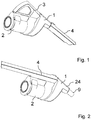
- Fig. 1 shows a perspective partial view of a vacuum cleaner according to the invention. Shown is the perspective partial view of the vacuum cleaner according to the invention, which is constructed in the first (upper) configuration.
- the vacuum cleaner has a suction material container 2 for receiving suction material, a housing body 1, a handle 3 and a suction tube 4.
- a drive unit (not shown) is arranged, which is designed to generate a suction flow during operation.
- the suction material container 2 is detachably connected to the device body 1.
- the handle 3 is detachably connected to the suction material container 2 and the device body 1.
- the device body 1 and the suction tube 4 are detachably connected.
- the handle 3 and the suction tube 4 are connected to opposite ends of the device body 1.
- the device body 1 has a device body housing 24.
- the user When operating the in Fig. 1 With the vacuum cleaner shown, the user holds the vacuum cleaner by gripping the handle 3, which rests in the position on the suction material container 2, while an end (not shown) of the suction tube 4 pointing away from the device body 1 is directed towards the surface to be vacuumed (not shown), in order to suck up from this suction material (not shown). During operation, the suction air flow is generated, which flows through the suction pipe 4, the device body 1 and the suction material container 2.
- Fig. 2 shows a further perspective partial view of the vacuum cleaner according to the invention. Shown is the perspective partial view of the vacuum cleaner according to the invention, which is constructed in the second (lower) configuration.
- the suction material container 2 is detachably connected to the device body 1.
- the suction tube 4 is detachably connected to the suction material container 2 and the device body 1. Furthermore, the suction tube 4 is connected to the handle (not shown).
- the device body 1 has the mechanical interface 9.
- the mechanical interface 9 is designed to be connectable to a floor nozzle (not shown).
- the user When operating the in Fig. 2 As shown in the vacuum cleaner, the user holds the vacuum cleaner by gripping the suction tube 4 or the handle (not shown) which is detachably connected to an end (not shown) of the suction tube 4 that is opposite the end (not shown) of the suction tube 4 that is connected to the Device body 1 is detachably connected.
- the mechanical interface 9 is directed towards the surface to be vacuumed (not shown) in order to suck up from this suction material (not shown).
- the suction air flow is generated, which flows through the device body 1 and the suction material container 2.
- Fig. 3 shows a perspective view of a module according to the invention of the in Figs. 1 and 2 shown vacuum cleaner.
- the module 20 has two electrical interfaces 7, 8 and two mechanical interfaces 9, 10 at two plug-in points.
- the two mechanical interfaces 9, 10 are designed to be connected to the handle (not shown) and the suction tube (not shown) by means of a plug connection.
- the module 20 also has a one-piece suction channel 5 which comprises the mechanical interface 9, which forms an air inlet 14 for suction air into the device body 1, and an element 23 which forms an air outlet 15 for suction air from the device body 1.
- the module 20 has electronics 6, on the basis of which the electrical interfaces 7 are arranged on the mechanical interface 9 and the electrical interface 8 of the mechanical interface 10 are arranged.
- the electronics 6 are arranged on the suction channel 5.
- the electronics 6 furthermore have an electrical accumulator interface 11, which is designed for connection to an accumulator (not shown), an electrical drive unit interface 12, which is designed for connection to a drive unit, and a display element 13 which is designed to display a charge status of the accumulator.
- Fig. 4 shows a perspective partial view of a device body of the in FIG Figs. 1 and 2 shown vacuum cleaner.
- the module shown is integrated into the device body 1 in such a way that the two mechanical interfaces 9, 10 and the electrical accumulator interface 11 are accessible from the outside.
- the device body 1 has the device body housing 24 which encloses the module 20 in such a way that the two mechanical interfaces 9, 10 and the electrical accumulator interface 11 are accessible from the outside.
- the two mechanical interfaces 9, 10 are designed to be connected to the handle (not shown) and the suction tube (not shown) by means of a plug connection.
- Fig. 5 shows a further perspective partial view of the in Fig. 4 shown device body.
- the device body 1 is shown from one of the in Fig. 3 side shown opposite side.
- the device body 1 has a further mechanical interface 21 which is designed to be connected to the suction material container (not shown).
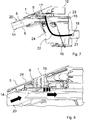
- FIG. 11 shows a partial cross-sectional view of the FIG Figs. 1 and 2 shown vacuum cleaner.
- the device body 1 and the suction material container 2, which are connected to one another, are shown.
- the drive unit 16 is arranged in the device body 1.
- the suction channel 5 defines an air path for the suction air flowing through the device body 1 during operation.
- the suction material container 2 is designed such that the vacuum cleaner is a cyclone vacuum cleaner.
- the suction material container 2 has one or more filters 25 in order to separate particles from the suction air stream flowing through the vacuum cleaner during operation.
- FIG. 11 shows another cross-sectional view of the FIG Fig. 4 and 5 shown device body.
- the electronics 6 are located above the air path with the air inlet 14 and the air outlet 15.
- the device body 1 has two pressure measuring points 17, 18.
- a negative pressure in the inflow of the suction material container (not shown) can be measured via the pressure measuring point 17 mounted on the electronics 6.
- the filling level of the suction material container or the degree of soiling of its filter can be determined via the further pressure measuring point 18 at an entrance to the drive unit 16, which is connected to a vacuum sensor or load cell (not shown) on the electronics 6 via a hose 22.
- FIG. 11 shows another partial cross-sectional view of the FIG Fig. 4 and 5 shown device body.
- the device body 1 can also have cooling fins 19 which are attached to the electronics 6.
- the cooling ribs 19 are arranged and designed in such a way that they protrude into the suction channel 5 and, during operation, immerse into the suction air flow flowing through the suction channel 5 and dissipate the heat generated at the electronics 6.
Landscapes
- Engineering & Computer Science (AREA)
- Mechanical Engineering (AREA)
- Electric Vacuum Cleaner (AREA)
Abstract
Description
- Die Erfindung betrifft einen Staubsauger. Insbesondere betrifft die Erfindung einen Staubsauger mit einem Handgriff, einem Saugrohr und einer Abscheideeinheit, welche einen Gerätekorpus mit einem Antriebsaggregat und einen Sauggutbehälter aufweist, der ausgebildet ist, Sauggut aufzunehmen. Üblicherweise ist das Saugrohr zwischen dem Gerätekorpus und einer Bodendüse angeordnet. Ein solcher Staubsauger wird auch als Stabstaubsauger, als Stick oder als Handstaubsauger bezeichnet. Er hat bei Betrieb nur durch die Bodendüse Kontakt zum saugenden Untergrund und wird von einem Nutzer mittels des Handgriffs geführt bzw. manövriert.
- Nachteilig an einem Staubsauger ist üblicherweise, dass sich ein Nutzer vor Kauf entscheiden muss, welche Art Staubsauger wie beispielsweise einen Stab- oder Rüsselstaubsauger er nutzen will. Diese Staubsauger unterscheiden sich in ihrer Bedien- und Führbarkeit. Je nach Einsatzort und von einem Untergrund wegzusaugendem Sauggut ist eine bestimmte Staubsaugerart besser geeignet als eine andere Staubsaugerart. Daher beststeht ein Bedarf an einem Staubsauger, der vielseitig und flexibel einsetzbar ist.
- Daher ist ein Staubsauger wünschenswert, bei dem die vorstehenden Staubsauger-Komponenten in mehreren Konfigurationen von einem Nutzer aufbaubar sind. Dazu muss der Staubsauger mechanische und elektrische Schnittstellen aufweisen, die für eine einfache und zufriedenstellende Handhabung ausgebildet und angeordnet sind.
- Der Erfindung stellt sich somit das Problem, einen Staubsauger bereitzustellen, der in mehreren Konfigurationen aufbaubar ist und mechanische und elektrische Schnittstellen aufweist, die derart angeordnet sind, dass sie leicht handhabbar sind.
- Erfindungsgemäß wird dieses Problem durch einen Staubsauger mit den Merkmalen des Patentanspruchs 1 gelöst. Vorteilhafte Ausgestaltungen und Weiterbildungen der Erfindung ergeben sich aus den nachfolgenden Unteransprüchen.
- Die mit der Erfindung erreichbaren Vorteile bestehen neben einer multifunktionalen Ausbildung des Moduls in dem Gerätekorpus und der damit einhergehenden leichten Handhabung darin, dass die Schnittstellen zentral angeordnet sind. Weiterhin ist eine Montage in der Endfertigung einfach und unkompliziert. Leitungsverlegungen im Staubsauger können durch das Modul vorkonfektioniert werden und müssen nicht am Band montiert werden. Zudem können Varianten des Moduls ausgebildet werden und weitere Funktionen integriert werden. Das Modul ermöglicht den Zusammenschluss einer Vielzahl von Schnittstellen. Es können relativ einfach verschiedene Konfigurationen des Staubsaugers gebildet werden.
- Die Erfindung betrifft einen Staubsauger mit einem Handgriff, einem Saugrohr, einem ein Antriebsaggregat enthaltenden Gerätekorpus und einem Sauggutbehälter zur Aufnahme von Sauggut, wobei der Handgriff, das Saugrohr, der Gerätekorpus in einer ersten (unteren) Konfiguration und in einer zweiten (oberen) Konfiguration miteinander verbunden sein können, wobei in der ersten (unteren) Konfiguration das Saugrohr zwischen dem Gerätekorpus und dem Handgriff angeordnet ist, so dass das Saugrohr bei Betrieb saugluftdurchströmungsfrei ist, und in der zweiten (oberen) Konfiguration der Saugrohr derart an dem Gerätekorpus und dem Sauggutbehälter angeordnet ist, dass das angesaugte Sauggut auf dem Weg von einem zu saugenden Untergrund in den Sauggutbehälter das Saugrohr passiert, wobei der Gerätekorpus an zwei Steckstellen jeweils mit dem Handgriff und dem Saugrohr verbindbar ist und ein Modul aufweist, das an den zwei Steckstellen zwei elektrische Schnittstellen und zwei mechanische Schnittstellen aufweist, wobei die zwei mechanischen Schnittstellen ausgebildet sind, jeweils mit dem Handgriff und dem Saugrohr mittels einer Steckverbindung verbunden zu werden. Bevorzugt ist eine mechanische Schnittstelle dazu ausgebildet, mit einer Bodendüse des Staubsaugers mittels einer Steckverbindung verbunden zu werden.
- Der Sauggutbehälter ist ausgelegt, das Sauggut aufzunehmen. Der Gerätekorpus ist weiterhin mit dem Sauggutbehälter verbindbar und/oder verbunden. Er enthält das Antriebsaggregat bevorzugt in Form eines Gebläses, das ausgelegt ist, bei Betrieb einen Saugluftstrom derart zu erzeugen, dass das Sauggut in den Sauggutbehälter gesaugt wird. Die Steckstellen des Gerätekorpus sind derart ausgelegt, dass in Abhängigkeit von der Konfiguration, in der der Staubsauger aufgebaut ist, mit dem Saugrohr oder dem Handgriff verbunden zu werden, auch wenn das Umstecken des Saugrohrs auf beide Steckstellen sinnvoll ist, aber nicht das Umstecken des Handgriffs entsprechend den beiden vorstehend beschriebenen Konfigurationen. Die mechanischen Schnittstellen sind derart ausgelegt, jeweils über eine Steckverbindung mit dem Saugrohr bzw. dem Handgriff verbunden zu werden, während die elektrischen Schnittstellen an den Steckstellen bevorzugt derart ausgelegt sind, dass der Staubsauger ein- und ausschaltbar ist.
- In einer bevorzugten Ausführungsform weist das Modul einen Saugkanal auf, der eine der beiden mechanischen Schnittstellen, die einen Lufteintritt für Saugluft in den Gerätekorpus bildet, und ein Element umfasst, das einen Luftaustritt für die Saugluft aus dem Gerätekorpus bildet. Der Saugkanal weist also bevorzugt eine der beiden mechanischen Schnittstellen, die beispielsweise bei Betrieb mit dem Saugrohr oder der Bodendüse verbunden sein kann, und das den Luftaustritt bildende Element auf. Die andere der beiden mechanischen Schnittstellen ist in Abhängeigeit von der Staubsauger-Konfiguration mit dem Saugrohr oder dem Handgriff bei Betrieb verbunden. Das Saugkanal definiert einen Luftweg für die bei Betrieb durch den Gerätekorpus strömende Saugluft.
- Bevorzugt weist das Modul weiterhin eine Elektronik auf, ausgehend von jeweils eine der elektrischen Schnittstellen jeweils an einer der mechanischen Schnittstellen angeordnet sind. Dadurch wird eine durchgehende Funktionstüchtigkeit gewährleistet.
- Der Staubsauger ist bevorzugt ein Akkustaubsauger. D.h., der Staubsauger weist einen Akkumulator auf und ist ausgelegt, mittels des Akkumulators als Stromquelle betrieben zu werden. Dadurch kann der Staubsauger kabellos betrieben werden, was seine Reichweite erhöhen kann. Der Akkumulator ist bevorzugt mit dem Sauggutbehälter und/oder dem Gerätekorpus bevorzugter dem Gerätekorpus verbindbar.
- In einen bevorzugten Ausführungsform weist die Elektronik weiterhin eine elektrische Akkumulator-Schnittstelle auf, die zur Verbindung mit einem Akkumulator ausgebildet ist. Dadurch kann eine Kontaktierung des Akkumulators mit der Elektronik auf einfache Weise realisiert werden. Bevorzugt weist die Elektronik weiterhin ein Anzeigeelement auf. Das Anzeigeelement ist bevorzugt ausgebildet, einen Ladezustand des Akkumulators anzuzeigen. Dadurch kann der Ladezustand des Akkumulators visualisiert werden. Das Anzeigeelement ist bevorzugt eine optische Anzeige, die bedarfsgerecht ausgebildet kann, so dass Ausstattungsvarianten des Staubsaugers möglich sind. Die optische Anzeige kann alternativ oder zusätzlich ausgelegt sein, eine Befüllungsanzeige und/oder eine Automatikfunktion anzuzeigen. Um Staubsauger-Varianten und entsprechende Schnittstellen in den Staubsauger zu integrieren, muss jeweils nur das Modul ausgetauscht werden, während die anderen Staubsauger-Komponenten gleich bleiben, was zu einer deutlichen Vereinfachung der Variantenbildung führt.
- Alternativ oder zusätzlich weist die Elektronik eine elektrische Antriebsaggregat-Schnittstelle auf, die zur Verbindung mit einem Antriebsaggregat ausgebildet ist. Dadurch kann eine Verbindung des Antriebsaggregats mit der Elektronik auf einfache Weise realisiert werden.
- In einer bevorzugten Ausführungsform ist die Elektronik auf dem Saugkanal angeordnet. Dadurch kann die Elektronik platzsparend und zentral angeordnet sein.
- Bevorzugt ist das Modul derart in den Gerätekorpus integriert, dass die zwei mechanischen Schnittstellen und die elektrische Akkumulator-Schnittstelle von außen zugänglich sind. Durch die Anordnung der mechanischen Schnittstellen an einem Modul, das nur von einem Gerätekorpus-Gehäuse des Gerätekorpus, die das Design bilden, umfasst ist, ist ein optimaler Fluss der mechanischen Belastungen über die beiden mechanischen Schnittstellen möglich. Insbesondere funktioniert der Saugkanal als Träger der mechanischen Belastung so wie eine Art Wirbelsäule im Staubsauger. Der Gerätekorpus weist bevorzugt das Gerätekorpus-Gehäuse auf, die das Modul umschließen, so dass die zwei mechanischen Schnittstellen und die elektrische Akkumulator-Schnittstelle von außen zugänglich sind, die Elektronik aber von den Gehäuseteilen umgeben ist. Dadurch wird die Elektronik weiterhin geschützt.
- In einer bevorzugten Ausführungsform ist der Saugkanal einstückig bzw. einteilig ausgebildet. Dadurch wird verhindert, dass bei Betrieb Saugluft aus dem Saugkanal entweichen kann. Durch Einbringen des gesamten Luftweges im Gerätekorpus in den einteiligen Saugkanal ist es nur notwendig eine Dichtstelle zum Sauggutbehälter einzubringen. Somit lassen sich Verluste und/oder Verwirbelungen in der Anströmung zum Sauggutbehälter bei Betrieb reduzieren. Dies ist insbesondere bei der Auslegung eines akkubetriebenen Staubsaugers vorteilhaft, da nur eine begrenzte Energie zur Verfügung steht.
- Bevorzugt weist der Staubsauger eine Steuer- oder Regeleinheit auf, die ausgebildet ist, eine Leistung des Staubsaugers zu steuern oder zu regeln.
- Bevorzugt weist die Elektronik weiterhin eine Druckmessstelle auf, die ausgebildet ist, einen Unterdruck in einem Zustrom des Saugluftbehälters zu messen. Insbesondere wenn sich die Elektronik des Staubsaugers direkt oberhalb des durch den Saugkanal definierten Luftweges befindet, kann über die an der Elektronik fest montierte Druckmessstelle der Unterdruck im Zustrom des Sauggutbehälters gemessen werden.
- Bevorzugt ist die Steuer- oder Regeleinheit weiterhin ausgebildet, über den ermittelten Unterdruck in der Anströmung insbesondere im Lufteintritt des Saugkanals eine Automatikfunktion zu generieren, die eine Saugleistung des Staubsaugers in Abhängigkeit eines zu saugenden Untergrunds wie Bodenbelag zu steuern oder zu regeln.
- In einer bevorzugten Ausführungsform weist der Staubsauger eine weitere Druckmessstelle, die am Zugang des Antriebsaggregats des Staubsaugers angeordnet ist und über einen Schlauch mit einem an der Elektronik angeordneten Unterdrucksensor oder -messdose verbunden ist, und die Steuer- oder Regeleinheit auf, die weiterhin ausgebildet ist, anhand von mittels der weiteren Druckmessstelle und dem Unterdrucksensor oder -messdose ermittelten Werten einen Füllstand des Sauggutbehälters und/oder einen Verschmutzungsgrad von einem Filter des Sauggutbehälters zu ermitteln. Dadurch kann sichergestellt werden, dass der Staubsauger nicht mit vollem Sauggutbehälter und/oder stark verschmutztem Filter betrieben wird, was seine Leistung verschlechtert.
- Bevorzugt weist der Staubsauger mindestens eine Kühlrippe auf, die an der Elektronik angeordnet ist und in den Saugkanal hineinragt, so dass sie in einen durch den Saugkanal durchströmenden Luftstrom eintaucht. Mittels der Kühlrippen kann die an der Elektronik entstehende Wärme abgeführt werden.
- Der Staubsauger kann eine Bodendüse aufweisen, die mit dem Saugrohr verbindbar ist. Die Bodendüse ist bevorzugt derart ausgebildet, dass sie auch mit dem Gerätekorpus verbindbar ist. Die elektrischen Schnittstellen sind bevorzugt ausgelegt, ein elektrisches Signal und/oder Energie an die Bodendüse weiterzuleiten. Bevorzugt weist die Elektronik eine elektrische Bodendüsen-Schnittstelle auf.
- Bevorzugt sind der Sauggutbehälter und der Gerätekorpus miteinander lösbar verbindbar. Bevorzugt weist der Gerätekorpus eine weitere mechanische Schnittstelle auf, die mit dem Sauggutbehälter verbindbar ist.
- Der Staubsauger ist bevorzugt handgeführt, wobei unter dem Ausdruck "handgeführt" zu verstehen ist, dass der Staubsauger per Hand von dem Nutzer bei Betrieb mittels des Handgriffs geführt wird.
- In einer bevorzugten Ausführungsform ist der Staubsauger als Zyklon-Staubsauger ausgebildet. Unter dem Begriff "Zyklon-Staubsauger" ist ein Staubsauger zu verstehen, der beutellos ist und in einem in den Staubsauger eintretenden Luftstrom Wirbel und etwaige Verwirbelungen erzeugt werden, wodurch das Sauggut wie z.B. Staubteilchen aufgrund von Fliehkraft in eine vorbestimmte Richtung gedrückt und abgeschieden werden. Unter dem Ausdruck "beutellos" ist zu verstehen, dass das Sauggut in dem Staubsauger direkt im Sauggutbehälter gesammelt wird, ohne dass in diesem ein Beutel oder ein ähnliches Wechselfiltermedium zur Aufnahme von Sauggut angeordnet ist, so dass der Nutzer zur Entleerung des Saugguts aus dem Sauggutbehälter keinen Beutel oder dgl. aus dem Sauggutbehälter entnimmt. Der Staubsauger kann aber ein oder mehrere Filtermedien aufweisen, die verhindern, dass Sauggut in das in dem Gerätekorpus angeordneten Antriebsaggregat gelangt.
- Bevorzugt ist der Staubsauger in einer dritten Konfiguration saugrohrlos betreibbar, in der der Handgriff lösbar mit dem Gerätekorpus und dem Sauggutbehälter verbunden ist. Bei Betrieb wird Sauggut durch die mechanische Schnittstelle, die den Lufteintritt bildet, in den Sauggutbehälter gesaugt.
- Ein Ausführungsbeispiel der Erfindung ist in den Zeichnungen rein schematisch dargestellt und wird nachfolgend näher beschrieben. Es zeigt schematisch und nicht maßstabsgerecht
- Fig. 1
- eine perspektivische Teil-Ansicht eines erfindungsgemäßen Staubsaugers;
- Fig. 2
- eine weitere perspektivische Teil-Ansicht des erfindungsgemäßen Staubsaugers;
- Fig. 3
- eine perspektivische Ansicht eines erfindungsgemäßen Moduls des in
Fig. 1 und 2 gezeigten Staubsaugers; - Fig. 4
- eine perspektivische Teilansicht eines Gerätekorpus in
Fig. 1 und 2 gezeigten Staubsaugers; - Fig. 5
- eine weitere perspektivische Teilansicht des in
Fig. 4 gezeigten Gerätekorpus; - Fig. 6
- eine Teil-Querschnittsansicht des in
Fig. 1 und 2 gezeigten Staubsaugers; - Fig. 7
- eine Querschnittsansicht des in
Fig. 4 und5 gezeigten Gerätekorpus; und - Fig. 8
- eine weitere Teil-Querschnittsansicht des in
Fig. 4 und5 gezeigten Gerätekorpus. -
Fig. 1 zeigt eine perspektivische Teil-Ansicht eines erfindungsgemäßen Staubsaugers. Gezeigt ist die perspektivische Teil-Ansicht des erfindungsgemäßen Staubsaugers, der in der ersten (oberen) Konfiguration aufgebaut ist. Der Staubsauger weist einen Sauggutbehälter 2 zur Aufnahme von Sauggut, einen Gehäusekorpus 1, einen Handgriff 3 und ein Saugrohr 4 auf. In dem Gerätekorpus 1 ist ein Antriebsaggregat (nicht gezeigt) angeordnet, das ausgebildet ist, bei Betrieb einen Saugstrom zu erzeugen. Der Sauggutbehälter 2 ist mit dem Gerätekorpus 1 lösbar verbunden. Der Handgriff 3 ist mit dem Sauggutbehälter 2 und dem Gerätekorpus 1 lösbar verbunden. Der Gerätekorpus 1 und das Saugrohr 4 sind lösbar verbunden. Der Handgriff 3 und das Saugrohr 4 sind mit gegenüberliegenden Enden des Gerätekorpus 1 verbunden. Der Gerätekorpus 1 weist ein Gerätekorpus-Gehäuse 24 auf. - Bei Betrieb des in
Fig. 1 gezeigten Staubsaugers hält der Nutzer den Staubsauger durch Greifen des Handgriffs 3, der in der Position auf dem Sauggutbehälter 2 aufliegt, während ein von dem Gerätekorpus 1 wegweisendes Ende (nicht gezeigt) des Saugrohrs 4 auf den zu saugenden Untergrund (nicht gezeigt) gerichtet ist, um von diesem Sauggut (nicht gezeigt) aufzusaugen. Bei Betrieb wird der Saugluftstrom erzeugt, der durch das Saugrohr 4, den Gerätekorpus 1 und den Sauggutbehälter 2 strömt. -
Fig. 2 zeigt eine weitere perspektivische Teil-Ansicht des erfindungsgemäßen Staubsaugers. Gezeigt ist die perspektivische Teil-Ansicht des erfindungsgemäßen Staubsaugers, der in der zweiten (unteren) Konfiguration aufgebaut ist. Der Sauggutbehälter 2 ist mit dem Gerätekorpus 1 lösbar verbunden. Das Saugrohr 4 ist mit dem Sauggutbehälter 2 und dem Gerätekorpus 1 lösbar verbunden. Weiterhin ist das Saugrohr 4 mit dem Handgriff (nicht gezeigt) verbunden. Der Gerätekorpus 1 weist die mechanische Schnittstelle 9 auf. Die mechanische Schnittstelle 9 ist ausgebildet, mit einer Bodendüse (nicht gezeigt) verbindbar zu sein. - Bei Betrieb des in
Fig. 2 gezeigten Staubsaugers hält der Nutzer den Staubsauger durch Greifen des Saugrohrs 4 oder des Handgriffs (nicht gezeigt), der mit einem Ende (nicht gezeigt) des Saugrohrs 4 lösbar verbunden ist, das dem Ende (nicht gezeigt) des Saugrohrs 4 gegenüberliegt, das mit dem Gerätekorpus 1 lösbar verbunden ist. Die mechanische Schnittstelle 9 ist auf den zu saugenden Untergrund (nicht gezeigt) gerichtet, um von diesem Sauggut (nicht gezeigt) aufzusaugen. Bei Betrieb wird der Saugluftstrom erzeugt, der durch den Gerätekorpus 1 und den Sauggutbehälter 2 strömt. -
Fig. 3 zeigt eine perspektivische Ansicht eines erfindungsgemäßen Moduls des inFig. 1 und 2 gezeigten Staubsaugers. Das Modul 20 weist an zwei Steckstellen zwei elektrische Schnittstellen 7, 8 und zwei mechanische Schnittstellen 9, 10 auf. Die zwei mechanischen Schnittstellen 9, 10 sind ausgebildet, jeweils mit dem Handgriff (nicht gezeigt) und dem Saugrohr (nicht gezeigt) mittels einer Steckverbindung verbunden zu werden. Das Modul 20 weist ferner einen einstückigen Saugkanal 5 auf, der die mechanische Schnittstelle 9, die einen Lufteintritt 14 für Saugluft in den Gerätekorpus 1 bildet, und ein Element 23 umfasst, die einen Luftaustritt 15 für Saugluft aus dem Gerätekorpus 1 bildet. - Weiterhin weist das Modul 20 eine Elektronik 6 auf, ausgehend von der die elektrischen Schnittstellen 7 an der mechanischen Schnittstelle 9 und die elektrische Schnittstelle 8 der mechanischen Schnittstelle 10 angeordnet sind. Die Elektronik 6 ist auf dem Saugkanal 5 angeordnet. Die Elektronik 6 weist weiterhin eine elektrische Akkumulator-Schnittstelle 11, die zur Verbindung mit einem Akkumulator (nicht gezeigt) ausgebildet ist, eine elektrische Antriebsaggregat-Schnittstelle 12, die zur Verbindung mit einem Antriebsaggregat ausgebildet ist, und ein Anzeigeelement 13 auf, das ausgebildet ist, einen Ladezustand des Akkumulators anzuzeigen.
-
Fig. 4 zeigt eine perspektivische Teilansicht eines Gerätekorpus des inFig. 1 und 2 gezeigten Staubsaugers. Das inFig. 3 gezeigte Modul ist derart in den Gerätekorpus 1 integriert, dass die zwei mechanischen Schnittstellen 9, 10 und die elektrische Akkumulator-Schnittstelle 11 von außen zugänglich sind. Der Gerätekorpus 1 weist das Gerätekorpus-Gehäuse 24 auf, das das Modul 20 derart umhüllt, die zwei mechanischen Schnittstellen 9, 10 und die elektrische Akkumulator-Schnittstelle 11 von außen zugänglich sind. Die zwei mechanischen Schnittstellen 9, 10 sind ausgebildet, jeweils mit dem Handgriff (nicht gezeigt) und dem Saugrohr (nicht gezeigt) mittels einer Steckverbindung verbunden zu werden. -
Fig. 5 zeigt eine weitere perspektivische Teilansicht des inFig. 4 gezeigten Gerätekorpus. Gezeigt ist der Gerätekorpus 1 von einer der inFig. 3 gezeigten Seite gegenüberliegenden Seite. Der Gerätekorpus 1 weist eine weitere mechanische Schnittstelle 21 auf, die ausgebildet ist, mit dem Sauggutbehälter (nicht gezeigt) verbunden zu werden. -
Fig. 6 zeigt eine Teil-Querschnittsansicht des inFig. 1 und 2 gezeigten Staubsaugers. Gezeigt sind der Gerätekorpus 1 und der Sauggutbehälter 2, die miteinander verbunden sind. In dem Gerätekorpus 1 ist das Antriebsaggregat 16 angeordnet. Der Saugkanal 5 definiert einen Luftweg für die bei Betrieb durch den Gerätekorpus 1 strömende Saugluft. Der Sauggutbehälter 2 ist derart ausgebildet, dass der Staubsauger ein Zyklon-Staubsauger ist. Der Sauggutbehälter 2 weist einen oder mehrere Filter 25 auf, um Partikel aus dem bei Betrieb durch den Staubsauger strömenden Saugluftstrom zu trennen. -
Fig. 7 zeigt eine weitere Querschnittsansicht des inFig. 4 und5 gezeigten Gerätekorpus. Die Elektronik 6 befindet sich oberhalb des Luftweges mit dem Lufteinritt 14 und dem Luftaustritt 15. Der Gerätekorpus 1 weist zwei Druckmessstellen 17, 18 auf. Über die an der Elektronik 6 montierte Druckmessstelle 17 kann bei Betrieb ein Unterdruck im Zustrom des Sauggutbehälter (nicht gezeigt) gemessen werden. Über die weitere Druckmessstelle 18 an einem Zugang des Antriebsaggregats 16, die über einen Schlauch 22 an einen Unterdrucksensor oder -messdose (nicht gezeigt) auf der Elektronik 6 angeschlossen ist, kann ein Füllstand des Sauggutbehälters bzw. ein Verschmutzungsgrad seines Filters ermittelt werden. -
Fig. 8 zeigt eine weitere Teil-Querschnittsansicht des inFig. 4 und5 gezeigten Gerätekorpus. Der Gerätekorpus 1 kann weiterhin Kühlrippen 19 aufweisen, die auf der Elektronik 6 angebracht sind. Die Kühlrippen 19 sind derart angeordnet und ausgebildet, dass sie in den Saugkanal 5 hineinragen und bei Betrieb in den durch den Saugkanal 5 strömenden Saugluftstrom eintauchen und die an der Elektronik 6 entstehende Wärme abführen. -
- 1
- Gerätekorpus
- 2
- Sauggutbehälter
- 3
- Handgriff
- 4
- Saugrohr
- 5
- Saugkanal
- 6
- Elektronik
- 7
- elektrische Schnittstelle
- 8
- weitere elektrische Schnittstelle
- 9
- mechanische Schnittstelle
- 10
- weitere mechanische Schnittstelle
- 11
- elektrische Akkumulator-Schnittstelle
- 12
- elektrische Antriebsaggregat-Schnittstelle
- 13
- Anzeigeelement
- 14
- Lufteintritt
- 15
- Luftaustritt
- 16
- Antriebsaggregat
- 17
- Druckmessstelle
- 18
- weitere Druckmessstelle
- 19
- Kühlrippe
- 20
- Modul
- 21
- weitere mechanische Schnittstelle
- 22
- Schlauch
- 23
- Element
- 24
- Gerätekorpus-Gehäuse
- 25
- Filter
Claims (10)
- Staubsauger mit einem Handgriff (3), einem Saugrohr (4), einem ein Antriebsaggregat enthaltenden Gerätekorpus (1) und einem Sauggutbehälter (2) zur Aufnahme von Sauggut, wobei der Handgriff (3), das Saugrohr (4), der Gerätekorpus (1) in einer ersten (unteren) Konfiguration und in einer zweiten (oberen) Konfiguration miteinander verbunden sein können, wobei in der ersten (unteren) Konfiguration das Saugrohr (4) zwischen dem Gerätekorpus (1) und dem Handgriff (3) angeordnet ist, so dass das Saugrohr (4) bei Betrieb saugluftdurchströmungsfrei ist, und in der zweiten (oberen) Konfiguration der Saugrohr (4) derart an dem Gerätekorpus (1) und dem Sauggutbehälter (2) angeordnet ist, dass das angesaugte Sauggut auf dem Weg von einem zu saugenden Untergrund in den Sauggutbehälter (2) das Saugrohr (4) passiert, wobei der Gerätekorpus (1) an zwei Steckstellen jeweils mit dem Handgriff (3) und dem Saugrohr (4) verbindbar ist und ein Modul (20) aufweist, das an den zwei Steckstellen zwei elektrische Schnittstellen (7, 8) und zwei mechanische Schnittstellen (9, 10) aufweist, wobei die zwei mechanischen Schnittstellen (9, 10) ausgebildet sind, jeweils mit dem Handgriff (3) und dem Saugrohr (4) mittels einer Steckverbindung verbunden zu werden.
- Staubsauger nach Anspruch 1, dadurch gekennzeichnet, dass das Modul (20) einen Saugkanal (5) aufweist, der eine (9) der beiden mechanischen Schnittstellen (9, 10) umfasst, die einen Lufteintritt (14) für Saugluft in den Gerätekorpus (1) bildet, und ein Element umfasst, das einen Luftaustritt (15) für die Saugluft aus dem Gerätekorpus (1) bildet.
- Staubsauger nach Anspruch 1 oder 2, dadurch gekennzeichnet, dass das Modul (20) weiterhin eine Elektronik (6) aufweist, ausgehend von der jeweils eine der elektrischen Schnittstellen (7, 8) jeweils an einer der mechanischen Schnittstellen (9, 10) angeordnet sind.
- Staubsauger nach Anspruch 3, dadurch gekennzeichnet, dass die Elektronik (6) weiterhin eine elektrische Akkumulator-Schnittstelle (11), die zur Verbindung mit einem Akkumulator ausgebildet ist, eine elektrische Antriebsaggregat-Schnittstelle (12), die zur Verbindung mit einem Antriebsaggregat ausgebildet ist, und/oder ein Anzeigeelement (13) aufweist.
- Staubsauger nach Anspruch 3 oder 4, dadurch gekennzeichnet, dass die Elektronik (6) auf dem Saugkanal (5) angeordnet ist.
- Staubsauger nach einem der vorangehenden Ansprüche, dadurch gekennzeichnet, dass das Modul (20) derart in den Gerätekorpus (1) integriert ist, dass die zwei mechanischen Schnittstellen (9, 10) und die elektrische Akkumulator-Schnittstelle (11) von außen zugänglich sind.
- Staubsauger nach einem der vorangehenden Ansprüche 2 bis 6, dadurch gekennzeichnet, dass der Saugkanal (5) einstückig ausgebildet ist.
- Staubsauger nach einem der vorangehenden Ansprüche 3 bis 7, dadurch gekennzeichnet, dass die Elektronik (6) weiterhin eine Druckmessstelle (17) aufweist, die ausgebildet ist, einen Unterdruck in einem Zustrom des Saugluftbehälters (2) zu messen.
- Staubsauger nach einem der vorangehenden Ansprüche, gekennzeichnet durch eine weitere Druckmessstelle (18), die am Zugang des Antriebsaggregats des Staubsaugers angeordnet ist und über einen Schlauch (22) mit einem an der Elektronik (6) angeordneten Unterdrucksensor oder -messdose verbunden ist, und durch eine Steuer- oder Regeleinheit, die ausgebildet ist, anhand von mittels der weiteren Druckmessstelle und dem Unterdrucksensor oder -messdose ermittelten Werten einen Füllstand des Sauggutbehälters (2) und/oder einen Verschmutzungsgrad von einem Filter des Sauggutbehälters (2) zu ermitteln.
- Staubsauger nach einem der vorangehenden Ansprüche 3 bis 9, gekennzeichnet durch mindestens eine Kühlrippe (19), die an der Elektronik (6) angeordnet ist und in den Saugkanal (5) hineinragt, so dass sie in einen bei Betrieb durch den Saugkanal (5) durchströmenden Luftstrom eintaucht.
Applications Claiming Priority (1)
| Application Number | Priority Date | Filing Date | Title |
|---|---|---|---|
| DE102019121487.4A DE102019121487A1 (de) | 2019-08-09 | 2019-08-09 | Staubsauger |
Publications (1)
| Publication Number | Publication Date |
|---|---|
| EP3772304A1 true EP3772304A1 (de) | 2021-02-10 |
Family
ID=71620219
Family Applications (1)
| Application Number | Title | Priority Date | Filing Date |
|---|---|---|---|
| EP20185840.4A Pending EP3772304A1 (de) | 2019-08-09 | 2020-07-15 | Staubsauger |
Country Status (2)
| Country | Link |
|---|---|
| EP (1) | EP3772304A1 (de) |
| DE (1) | DE102019121487A1 (de) |
Cited By (1)
| Publication number | Priority date | Publication date | Assignee | Title |
|---|---|---|---|---|
| EP4627990A1 (de) | 2024-04-05 | 2025-10-08 | Miele & Cie. KG | Staubsauger |
Citations (2)
| Publication number | Priority date | Publication date | Assignee | Title |
|---|---|---|---|---|
| CN105832246A (zh) * | 2015-01-13 | 2016-08-10 | 科沃斯机器人有限公司 | 真空吸尘器 |
| DE102016105475A1 (de) * | 2016-03-23 | 2017-09-28 | Miele & Cie. Kg | Staubsauger |
-
2019
- 2019-08-09 DE DE102019121487.4A patent/DE102019121487A1/de active Pending
-
2020
- 2020-07-15 EP EP20185840.4A patent/EP3772304A1/de active Pending
Patent Citations (2)
| Publication number | Priority date | Publication date | Assignee | Title |
|---|---|---|---|---|
| CN105832246A (zh) * | 2015-01-13 | 2016-08-10 | 科沃斯机器人有限公司 | 真空吸尘器 |
| DE102016105475A1 (de) * | 2016-03-23 | 2017-09-28 | Miele & Cie. Kg | Staubsauger |
Cited By (2)
| Publication number | Priority date | Publication date | Assignee | Title |
|---|---|---|---|---|
| EP4627990A1 (de) | 2024-04-05 | 2025-10-08 | Miele & Cie. KG | Staubsauger |
| BE1032509A1 (de) | 2024-04-05 | 2025-10-28 | Miele & Cie | Staubsauger |
Also Published As
| Publication number | Publication date |
|---|---|
| DE102019121487A1 (de) | 2021-02-11 |
Similar Documents
| Publication | Publication Date | Title |
|---|---|---|
| DE10058311C2 (de) | Zyklon-Staubauffangvorrichtung für einen Staubsauger | |
| DE112009002586B4 (de) | Handstaubsauger | |
| DE69507836T2 (de) | Filteranordnung für einen staubsauger | |
| DE10356156B4 (de) | Wirbelungs-Staubsammelvorrichtung eines Staubsaugers | |
| EP3081130B1 (de) | Hartflächenabsauggerät | |
| DE202017001077U1 (de) | Staubsauger | |
| EP3021726B1 (de) | Tragbares hartflächenreinigungsgerät | |
| DE202017007372U1 (de) | Reinigungsvorrichtung | |
| DE102017121209B4 (de) | Flächenreinigungsgerät | |
| DE102004003104A1 (de) | Griffrohr und mit einem solchen Griffrohr ausgestatteter Wirbelungs-Staubsauger | |
| EP3338611B1 (de) | Saugvorrichtung | |
| DE212020000707U1 (de) | Elektrowerkzeugsystem | |
| DE102019121487A1 (de) | Staubsauger | |
| DE102014119190A1 (de) | Saugdüse für einen elektromotorisch betriebenen Staubsauger | |
| EP3692879A1 (de) | Handgeführter zyklon-staubsauger | |
| DE102019102382A1 (de) | Sauggutsammelstation und System aus einer Sauggutsammelstation und einem Saugreinigungsgerät | |
| DE69205722T2 (de) | Staubsauger. | |
| DE102017121208A1 (de) | Flächenreinigungsgerät | |
| DE102019123150A1 (de) | Staubfilterbeutel | |
| EP3393322A1 (de) | Tragbares hartflächenreinigungsgerät | |
| EP3058893B1 (de) | Absaugvorrichtung | |
| DE1237276B (de) | Als Stielstaubsauger ausgebildetes Fussboden-pflegegeraet mit elektromotorisch angetriebenen umlaufenden Pflegewerkzeugen | |
| EP3692884A1 (de) | Sauggutbehälter und handgeführten zyklon-staubsauger | |
| DE202015105894U1 (de) | Handstaubsauger | |
| WO2017152953A1 (de) | Handgehaltenes sauggerät |
Legal Events
| Date | Code | Title | Description |
|---|---|---|---|
| PUAI | Public reference made under article 153(3) epc to a published international application that has entered the european phase |
Free format text: ORIGINAL CODE: 0009012 |
|
| STAA | Information on the status of an ep patent application or granted ep patent |
Free format text: STATUS: THE APPLICATION HAS BEEN PUBLISHED |
|
| STAA | Information on the status of an ep patent application or granted ep patent |
Free format text: STATUS: REQUEST FOR EXAMINATION WAS MADE |
|
| AK | Designated contracting states |
Kind code of ref document: A1 Designated state(s): AL AT BE BG CH CY CZ DE DK EE ES FI FR GB GR HR HU IE IS IT LI LT LU LV MC MK MT NL NO PL PT RO RS SE SI SK SM TR |
|
| AX | Request for extension of the european patent |
Extension state: BA ME |
|
| 17P | Request for examination filed |
Effective date: 20210115 |
|
| RBV | Designated contracting states (corrected) |
Designated state(s): AL AT BE BG CH CY CZ DE DK EE ES FI FR GB GR HR HU IE IS IT LI LT LU LV MC MK MT NL NO PL PT RO RS SE SI SK SM TR |
|
| STAA | Information on the status of an ep patent application or granted ep patent |
Free format text: STATUS: EXAMINATION IS IN PROGRESS |
|
| 17Q | First examination report despatched |
Effective date: 20230418 |
|
| GRAP | Despatch of communication of intention to grant a patent |
Free format text: ORIGINAL CODE: EPIDOSNIGR1 |
|
| STAA | Information on the status of an ep patent application or granted ep patent |
Free format text: STATUS: GRANT OF PATENT IS INTENDED |
|
| INTG | Intention to grant announced |
Effective date: 20260618 |
|
| GRAS | Grant fee paid |
Free format text: ORIGINAL CODE: EPIDOSNIGR3 |
|
| GRAA | (expected) grant |
Free format text: ORIGINAL CODE: 0009210 |
|
| STAA | Information on the status of an ep patent application or granted ep patent |
Free format text: STATUS: THE PATENT HAS BEEN GRANTED |