EP3771685B1 - Lademodul und verfahren zum transport von gütern - Google Patents
Lademodul und verfahren zum transport von gütern Download PDFInfo
- Publication number
- EP3771685B1 EP3771685B1 EP20189180.1A EP20189180A EP3771685B1 EP 3771685 B1 EP3771685 B1 EP 3771685B1 EP 20189180 A EP20189180 A EP 20189180A EP 3771685 B1 EP3771685 B1 EP 3771685B1
- Authority
- EP
- European Patent Office
- Prior art keywords
- loading
- roller elements
- loading system
- load
- row
- Prior art date
- Legal status (The legal status is an assumption and is not a legal conclusion. Google has not performed a legal analysis and makes no representation as to the accuracy of the status listed.)
- Active
Links
Images


Classifications
-
- B—PERFORMING OPERATIONS; TRANSPORTING
- B66—HOISTING; LIFTING; HAULING
- B66F—HOISTING, LIFTING, HAULING OR PUSHING, NOT OTHERWISE PROVIDED FOR, e.g. DEVICES WHICH APPLY A LIFTING OR PUSHING FORCE DIRECTLY TO THE SURFACE OF A LOAD
- B66F9/00—Devices for lifting or lowering bulky or heavy goods for loading or unloading purposes
- B66F9/06—Devices for lifting or lowering bulky or heavy goods for loading or unloading purposes movable, with their loads, on wheels or the like, e.g. fork-lift trucks
- B66F9/075—Constructional features or details
- B66F9/12—Platforms; Forks; Other load supporting or gripping members
-
- B—PERFORMING OPERATIONS; TRANSPORTING
- B60—VEHICLES IN GENERAL
- B60P—VEHICLES ADAPTED FOR LOAD TRANSPORTATION OR TO TRANSPORT, TO CARRY, OR TO COMPRISE SPECIAL LOADS OR OBJECTS
- B60P1/00—Vehicles predominantly for transporting loads and modified to facilitate loading, consolidating the load, or unloading
- B60P1/52—Vehicles predominantly for transporting loads and modified to facilitate loading, consolidating the load, or unloading using rollers in the load-transporting element
Definitions
- the invention relates to a loading module for transport of goods.
- a loading module for transport of goods.
- Such a loading module can for instance be used in the loading of containers or trucks.
- Document US 3549035 discloses a lift truck with a fork that has an elongated flat surface wedge guide for slight longitudinal movement in each of the tines, and roller bearing arranged transversely of the wedge for sustaining a load as said roller, embedded for half of their diameter in the wedge, are moved under the load by the said movement of the wedge which may be by hydraulic or automatic means.
- the present invention has for its object to provide a loading module whereby the above stated problems are obviated or at least reduced, and for instance a container loading space can be loaded in effective manner.
- the loading module according to the invention is also highly suitable for transporting long items such as (foundation) piles and the like.
- Providing a first row of roller elements enables the module to be displaced over a ground surface.
- the roller elements are for instance formed by barrels, cones, balls, wheels, belts and the like.
- Providing a row of roller elements achieves that the weight of the load is distributed over a relatively large number of roller elements and a relatively large surface area. This has the advantage that the point load on a ground surface is relatively limited compared to conventional systems.
- By further having the row of roller elements extend over a large part of the length of the loading module a stable position of the carrying surface during displacement of the loading module is further achieved. This is because holes, cracks, grooves have only a limited influence on several of the roller elements present in this first row, whereby the stability of the load on the carrying surface is maintained.
- Providing a second row of roller elements, wherein the rotation shafts of these roller elements lie at a greater distance from the ground surface, i.e. in practice higher, than the rotation shafts of the first row of roller elements enables a load to be placed on the carrying surface, or removed therefrom and set down at the desired location, in effective manner.
- This is realized by making use of a pneumatic and/or hydraulic lifting element which is configured to switch between the first transport mode and the second pick-up or set-down mode.
- the pneumatic and/or hydraulic lifting element ensures that the second row of roller elements is not in contact with the load on the carrying surface. This means that in this mode the roller elements do not protrude through openings in the carrying surface.
- the load therefore remains stable at the same position on the carrying surface, and the loading module according to the invention can be displaced to a desired location.
- Passing the loading module according to the invention from the transport mode to the second pick-up or set-down mode using the pneumatic and/or hydraulic lifting element enables cargo to be set down in effective manner.
- This is achieved in that in this mode the roller elements of the second row of roller elements protrude at least partially through the openings in the carrying surface and are thereby in direct or indirect contact with the load positioned thereon. It is hereby possible to displace the load over the carrying surface.
- the roller elements of the second row are preferably in a rolling contact with the roller elements of the first row, it is achieved that when the loading module is displaced over the ground surface, the load remains at substantially the same position relative to this ground surface, while the loading module is displaced.
- roller elements of the first row move over the ground surface. Because the roller elements of the second row of roller elements are in rolling contact with the first roller elements, they will co-rotate in the other direction. The load will thereby remain at substantially the same position relative to the ground surface while the carrying surface is moved along under the load, as it were.
- This is particularly advantageous in picking up and/or setting down of cargo using a loading module according to the invention.
- An additional advantage is that the loading module can be applied without modifications having to be made to for instance the loading bay. It is thus for instance not necessary to arrange rails in a ground surface.
- roller elements are preferably manufactured from material with a high friction coefficient, such as polyurethane, rubber and the like. It will be apparent that application of other materials is also possible.
- the lifting element is embodied as a pneumatic and/or hydraulic lifting element.
- a pneumatic lifting element can usually be embodied cost-effectively as compare to other lifting systems, and is additionally reliable.
- pneumatics are commonly available, for instance in the form of a compressed air system.
- such a pneumatic lifting system is robust in practice, and the pressure in the system is distributed substantially homogeneously. This for instance means that a uniform lifting or descending movement can be realized using the pneumatic lifting element.
- an (operating) pressure in the range of 1-10 bar results in an effective embodiment for the pneumatic loading module, wherein a pressure in the range of 1.5-4 bar is preferably employed, and the pressure most preferably amounts to about 2 bar.
- the lifting element can be provided as a hydraulic element which is filled with a liquid.
- a liquid can be water, oil or another suitable liquid.
- a further additional advantage of using a, currently preferred, pneumatic lifting element is that it is a relatively clean component compared to for instance a hydraulic element. This simplifies maintenance.
- the loading module it is achieved that a large part of the load, or even the whole load, can be positioned in a container and/or other loading space in one go. This reduces the number of movements having to be carried out during loading or unloading. It will be apparent that this greatly improves the effectiveness of the loading process, and thereby of the transport in general. The safety during loading is also improved. Damage to goods and/or persons is hereby avoided.
- the pneumatic and/or hydraulic lifting element provides for movement of the carrying surface in a substantially vertical direction relative to the second row of roller elements.
- the module switches to the first transport mode when the pneumatic and/or hydraulic lifting element is activated and in such a preferred embodiment the carrying surface is lifted, such that the roller elements of the second row of roller elements no longer protrude through the openings in the carrier surface.
- the second row of roller elements remain substantially in contact with the roller elements of the first row of roller elements, however, without affecting the position of the load relative to the carrying surface.
- This has the advantage that the rotation shafts of all the roller elements can be fixedly mounted and that in this embodiment only the carrying surface varies in (height) position as a result of the pneumatic and/or hydraulic lifting element.
- the pneumatic and/or hydraulic lifting element comprises a hose.
- the lifting element By embodying the lifting element at least partially as a hose it can be incorporated in effective manner in the loading module according to the invention.
- the hose preferably extends here over substantially the whole length of the loading module. This makes it possible to realize a homogenous lifting movement and also a homogenous descending movement of the carrying surface relative to the roller elements. If desired, it is also possible according to the invention to provide more than one hose.
- the hose is a type of firehose of for instance a canvas plastic material with a diameter of between 30 and 110 mm, preferably about 30 to 52 mm, such that when the pneumatic and/or hydraulic lifting element is activated, the carrying surface is displaced in upward direction over a distance of about 2-3 cm.
- the hose is about 2.5 cm high after activation thereof with for instance compressed air, and is about 70 mm wide and 5 mm high in non-activated state. It is the case here that different dimensions and/or a different number of hoses are possible, also depending on the specifications for the loading module.
- At least one hose is preferably provided, which preferably extends in longitudinal direction of the loading module according to the invention.
- a plurality of hoses is used, these for instance lying parallel or following a different pattern.
- An additional advantage of using a pneumatic and/or hydraulic lifting element is that, as an additional effect, a damping/protective effect is obtained for the load on the carrying surface. Unevennesses in the ground surface will thus for instance have less of an effect on the load placed on the carrying surface. Damage to the load is hereby avoided as far as possible, and the risk of the load falling off the carrying surface is also reduced.
- the carrying surface is configured to move upward and/or downward in accordance with the (currently preferred pneumatic) lifting means.
- a guide or a plurality of guides to guide the carrying surface unequivocally in a substantially vertical direction during lifting and/or descending thereof.
- the loading module further comprises a pneumatic coupling configured to couple a compressed air source to the pneumatic lifting element.
- the pneumatic lifting element can be coupled to a source in effective manner.
- a source is for instance a (present) compressed air line, or another source, including a hand pump, foot pump or other pump system.
- the pneumatic lifting element can be inflated in effective manner so as to thereby move the carrying surface in particular relative to the roller elements.
- the invention further relates to a loading system comprising one or more loading modules in an embodiment according to the invention, and one or more (currently preferred pneumatic) front modules.
- Such a loading system provides similar advantages and effects as described for the loading module.
- a front module is embodied substantially similarly to the loading module.
- the front module is preferably provided on the front side with a nose element.
- the front module is further preferably provided with a height decreasing toward the front side, such that the front module can be inserted under a load and/or can set down load more easily.
- the desired dimensioning can in particular be adapted to for instance a container size, such as a 20ft container, wherein two loading modules are for instance positioned one behind the other in longitudinal direction, with two or four tracks/rows adjacently of each other.
- a container size such as a 20ft container
- two loading modules are for instance positioned one behind the other in longitudinal direction, with two or four tracks/rows adjacently of each other.
- other configurations for the loading system according to the invention are likewise possible.
- use can thus for instance be made of four modules which are placed one behind the other in longitudinal direction, and use can be made of more than 3 tracks positioned adjacently of each other. In this way such a container can be loaded in a single run.
- Other loading spaces, such as those of trucks, can also be loaded in similar manner.
- the loading system comprises a number of spacers for connecting loading modules which are positioned adjacently of each other as seen in the usual direction of travel.
- the spacers are preferably provided adjustably in longitudinal direction. It is hereby possible to realize a fine adjustment for the distance between adjacent modules of the loading system. It is hereby for instance possible to compensate for production tolerances.
- Such an adjustable spacer makes use of an adjusting mechanism, for instance by making use of screws or bolts. In a currently preferred embodiment it is possible to bridge a distance of up to 4 cm of clearance. In practice, it has been found that this provides sufficient clearance to enable a desired fine adjustment.
- the spacer is preferably likewise provided with a spring element, for instance incorporated into the means for making the length of the spacer adjustable. A less rigid/stiff construction for the loading system according to the invention is obtained by using the spring element. This is particularly advantageous in the case of a ground surface with some unevennesses.
- the loading system comprises a support bar configured to hold the load in position when it is being set down.
- the load can, in addition to the drive via the double roller system, also be stopped additionally on the rear side by placing a type of bar/barrier, which is fixed to the ground, behind the load once the loading system is positioned in the loading space of for instance the trailer/container, and then reversing the unit, wherein the bar/barrier stops the pallets.
- a weight on wheels travel along behind the load, and when the load is in the trailer/container, 'put the brake on' the weight so that it stops the load when the unit is pulled from under it.
- a push chain with motor drive mounted on the rear side of the loading system, to push on the load while the system is pulled rearward out of the trailer/container. The chain here pushes against the pallets in a substantially horizontal direction.
- the loading system comprises a carrier plate configured to be arranged between the load and the carrying surface.
- the loading system further comprises an automatic loading system.
- an automatic loading system enables cargo to be arranged on the loading system according to the invention and then transported in the loading space in an even more effective manner.
- Such an automatic loading system for instance makes use of a conveyor belt which is incorporated in the ground surface.
- the invention further relates to a method for transport of goods, the method comprising the steps of:
- Such a method provides similar effects and advantages as described for the loading module and/or loading system. It has particularly been found that such a method enables an efficient and safe transport.
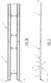
- Loading system 2 ( figure 1A ) is composed of a number of loading modules 4, preferably in combination with (pneumatic) front modules 6. An engagement 8 is provided, whereby a forklift truck, AGV or other vehicle can transport loading system 2. If desired, it is also possible to provide a drive directly on loading system 2. Loading system 2 is further provided with push plate or push bar 10 which is optionally movable in direction A over loading system 2.
- Loading system 2 extends in longitudinal direction over distance L and in width direction over distance B.
- Spacers 16 connect two adjacent tracks 12, 14 ( figure 1B ).
- spacer 16 is configured to hold tracks 12, 14 at a mutual distance, wherein the intermediate space for instance lies in the range of 300-750 mm, preferably in the range of 400-550 mm.
- spacer 16 is connected via bolt construction 18 to loading module 4.
- use is preferably made here of spring element 20, washer 22 and contact elements 24 of module 4 ( Figure 3 ).
- First row 26 of roller elements 28 is in contact with a ground surface during use.
- second row 30 of roller elements 32 ( figure 2 ).
- roller elements 32 of second row 30 can protrude wholly or partially through opening 34 arranged in carrying surface 36.
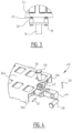
- front module 6 is provided with a decreasing thickness as seen in the direction toward the front side of loading system 2, wherein nose element 38 is arranged on the front side.
- Modules 4, 6 are coupled to each other in longitudinal direction L of loading system 2 using coupling 40.
- Coupling 40 ( figure 4 ) is a type of pin-hole connection with opening 42, connecting block 44, pins 46, 48 and spring pins 50, 52.
- Carrying surface 36 is formed on the upper side by surface 36a and in the shown embodiment is provided on the sides with bent edges 36b, 36c.
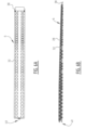
- Loading module 4 ( figures 5A-D ) is provided with space 54 between the mutually adjacent rows of roller elements 32 of module 4, 6 in which a (currently preferred pneumatic) lifting element in the form of hose 56 can be placed. Roller elements 28, 32 are arranged in module 4 using rotation shaft 58. Further provided in the shown embodiment is closing plate 60 for mutual fixing of the components of module 4.
- Front module 6 ( figures 6A-D ) is constructed in similar manner, wherein in the shown embodiment roller elements 28, 33 decrease in diameter in the direction of nose element 38 so as to thereby enable them to be inserted under the load more easily.
- This decrease in diameter of roller elements 28, 32 can be given a continuous progression, or in steps in order to limit the number of variations in diameters of roller elements.
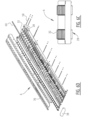
- roller elements 28, 32 are provided in fixedly arranged manner and are in mutual contact with contact surfaces 66 in both the first transport mode and the second pick-up or set-down mode.
- First roller elements 28 move over ground surface 64 during displacement of loading system 2, while in the pick-up or set-down mode roller elements 32 of second row 30 are in contact with load 62 in that these roller elements 32 protrude partially above carrying surface 36 through openings 34 therein.
- Carrier plate 67 is optionally additionally provided between load 62 and contact surfaces 66 of roller elements 32. If desired, it is also possible to provide ground surface 64 with optional conveyor belt system 68 for automatic loading of loading system 2. Due to movement of belt system 68 load 62 is in the second pick-up or set-down mode displaced over loading system 2 while remaining in the same spatial position.
- loading system 2 is composed of a number of loading modules which are provided on the front side of loading system 2 with front loading modules 6.
- Modules 4, 6 are mutually connected in longitudinal direction via couplings 40 and, in the case of a plurality of tracks 12, 14, held at a desired position in width direction B using spacers 16.
- loading system 2 is inserted with nose element 38 under load 62.
- loading system 2 By placing loading system 2 in the second pick-up or set-down mode by lowering or descending of lifting element 56 carrying surface 36 is moved preferably maximally downward relative to roller elements 28, 32.
- Contact surfaces 66 of roller elements 32 hereby come into contact with load 62, optionally via carrier plate 67, and load 62 will not move, or hardly so, relative to ground surface 64, while loading system 2 is inserted under this load 62.
- lifting element 56 is activated. In the shown embodiment activation is possible by connecting hose 56 to compressed air coupling 70 (indicated schematically in figure 1A ). By inflating hose 56 carrying surface 36 moves upward relative to roller elements 28, 32.
- Carrying surface 36 hereby comes to lie above contact surface 66 of roller elements 32 so that these roller elements 32 are no longer in contact with load 62.
- load 62 is carried wholly by carrying surface 36.
- load 62 will also move along in this transport mode and will therefore move relative to ground surface 64.
- lifting element 56 is deactivated, wherein in the shown embodiment air is pushed from hose 56, for instance by making use of the weight of load 62.
- Load 62 hereby comes to lie on contact surfaces 66 of roller elements 32.
- load 62 When loading system 2 is withdrawn, load 62 will hereby remain substantially at the same position relative to ground surface 64.
- Load 62 can hereby be set down at the desired location and loading system 2 can then be used to transport other goods. It is noted that it is possible to co-transport loading system 2 with load 62 in order to further simplify the logistical transport.
Landscapes
- Engineering & Computer Science (AREA)
- Transportation (AREA)
- Structural Engineering (AREA)
- Mechanical Engineering (AREA)
- Civil Engineering (AREA)
- Life Sciences & Earth Sciences (AREA)
- Geology (AREA)
- Rollers For Roller Conveyors For Transfer (AREA)
- Loading Or Unloading Of Vehicles (AREA)
Claims (11)
- Lademodul (4) für einen Transport von Gütern, das Lademodul (4) umfassend:- einen Rahmen, der bereitgestellt wird mit:- einer tragenden Oberfläche (36), die mit einer Anzahl von Öffnungen (34) bereitgestellt wird;- einer ersten Reihe (26) von Rollenelementen (28), die mit einer Rotationswelle (58) bereitgestellt werden; und- einer zweiten Reihe (30) von Rollenelementen (32), die mit einer Rotationswelle (58) bereitgestellt werden, die oberhalb der ersten Reihe (26) von Rollenelementen (28) liegt, und wobei die Rotationswellen (58) der zweiten Reihe (30) im Vergleich zu den Rotationswellen (58) der ersten Reihe (26) im Wesentlichen in einem größeren Abstand von einer Bodenoberfläche (64) liegen, und wobei in einem ersten Transportmodus die zweite Reihe (30) der Rollenelemente (32) im Wesentlichen unter der tragenden Oberfläche (36) liegt und in einem zweiten Aufnahme- oder Absetzmodus mindestens teilweise mit einer Kontaktfläche durch die Öffnungen (34) in der tragenden Oberfläche (36) herausragt; und- einem pneumatischen und/oder hydraulischen Hubelement (56), das in dem Rahmen angeordnet und so konfiguriert ist, dass das Lademodul (4) zwischen einem ersten Transportmodus und einem zweiten Aufnahme- oder Absetzmodus umschaltet, wobei das Hubelement (56) ein schlauchartiges Element (56) umfasst,dadurch gekennzeichnet, dass
die tragende Oberfläche (36) so konfiguriert ist, dass sie sich gemäß dem Hubelement (56) aufwärts und/oder abwärts bewegt. - Lademodul (4) nach Anspruch 1, wobei sich das schlauchartige Element (56) in Längsrichtung des Lademoduls (4) erstreckt.
- Lademodul (4) nach Anspruch 1 oder 2, wobei das Hubelement (56) ein pneumatisches Hubelement umfasst.
- Lademodul (4) nach Anspruch 3, ferner umfassend eine pneumatische Kupplung (70), die so konfiguriert ist, dass sie das pneumatische Hubelement mit einer Druckluftquelle koppelt.
- Ladesystem (2), umfassend ein oder mehrere Lademodule (4) nach einem der vorangehenden Ansprüche und ein oder mehrere Frontmodule (6).
- Ladesystem (2) nach Anspruch 5, ferner umfassend eine Anzahl von Abstandshaltern (16) zum Verbinden von Lademodulen (4), die in der üblichen Fahrtrichtung gesehen nebeneinander positioniert sind.
- Ladesystem (2) nach Anspruch 6, wobei die Abstandshalter (16) in Längsrichtung verstellbar sind.
- Ladesystem (2) nach einem der vorstehenden Ansprüche 5 bis 7, ferner umfassend einen Stützbalken, der so konfiguriert ist, dass er die Last (62) in Position hält, wenn sie abgesetzt wird.
- Ladesystem (2) nach einem der vorstehenden Ansprüche 5 bis 8, ferner umfassend eine Trägerplatte (67), die so konfiguriert ist, dass sie zwischen der Last (62) und der tragenden Oberfläche (36) angeordnet werden kann.
- Ladesystem (2) nach einem der vorstehenden Ansprüche 5 bis 9, ferner umfassend ein automatisches Ladesystem.
- Verfahren für einen Transport von Gütern, das Verfahren umfassend die folgenden Schritte:- Bereitstellen eines Lademoduls (4) und/oder eines Ladesystems (2) nach einem der vorstehenden Ansprüche;- Aufnehmen der Waren;- Verschieben der Waren; und- Absetzen der Waren.
Applications Claiming Priority (1)
| Application Number | Priority Date | Filing Date | Title |
|---|---|---|---|
| NL2023603A NL2023603B1 (nl) | 2019-08-02 | 2019-08-02 | Beladingsmodule en werkwijze voor transport van goederen |
Publications (2)
| Publication Number | Publication Date |
|---|---|
| EP3771685A1 EP3771685A1 (de) | 2021-02-03 |
| EP3771685B1 true EP3771685B1 (de) | 2023-05-03 |
Family
ID=69187848
Family Applications (1)
| Application Number | Title | Priority Date | Filing Date |
|---|---|---|---|
| EP20189180.1A Active EP3771685B1 (de) | 2019-08-02 | 2020-08-03 | Lademodul und verfahren zum transport von gütern |
Country Status (2)
| Country | Link |
|---|---|
| EP (1) | EP3771685B1 (de) |
| NL (1) | NL2023603B1 (de) |
Families Citing this family (1)
| Publication number | Priority date | Publication date | Assignee | Title |
|---|---|---|---|---|
| US20250376204A1 (en) * | 2024-06-11 | 2025-12-11 | Dimension Product Solutions LP | Automated loading and unloading apparatus |
Family Cites Families (5)
| Publication number | Priority date | Publication date | Assignee | Title |
|---|---|---|---|---|
| US3549035A (en) * | 1969-04-18 | 1970-12-22 | Donald W Soper | Fork assist |
| NL1018793C2 (nl) * | 2001-06-11 | 2002-12-12 | Sjoerd Meijer | Vorkheftruck met beladingssysteem. |
| NL2007576C2 (nl) * | 2011-10-12 | 2013-04-15 | Meijer St Jabik B V Geb | Stapelaar en werkwijze voor het verplaatsen van goederen. |
| US20160264385A1 (en) * | 2015-03-10 | 2016-09-15 | Roy C. Burrow | Convertible pallet jack with rollers |
| DK180626B1 (en) * | 2016-11-11 | 2021-11-04 | Dissing As | A device for positioning an object relatively to a support by inflatable air cushion members, a method of operating the device, and a method for moving an object |
-
2019
- 2019-08-02 NL NL2023603A patent/NL2023603B1/nl not_active IP Right Cessation
-
2020
- 2020-08-03 EP EP20189180.1A patent/EP3771685B1/de active Active
Also Published As
| Publication number | Publication date |
|---|---|
| EP3771685A1 (de) | 2021-02-03 |
| NL2023603B1 (nl) | 2021-02-23 |
Similar Documents
| Publication | Publication Date | Title |
|---|---|---|
| US8944239B2 (en) | Conveyor apparatus for loading or unloading packages from shipping containers | |
| EP0086211B1 (de) | Mechanische handhabungsanlage | |
| EP0467586B1 (de) | Handhabung von Ladegut | |
| US4544319A (en) | Cargo transfer system | |
| NL8700453A (nl) | Laadvloer van een vrachtvoertuig. | |
| US20140023462A1 (en) | Universal load-lifting means for the palettless handling of goods to be loaded onto paletts | |
| US5088585A (en) | Retractable roller ball cargo floor surface | |
| US5597282A (en) | Method and apparatus for unstacking and unloading a stacked load from one level to another level | |
| CN112299065A (zh) | 整车装车系统 | |
| CN115535654A (zh) | 一种嵌入式集装箱自动装卸车系统 | |
| US20100061834A1 (en) | Platform for carrying and transporting loads with an unrollable floor, and transport device with a platform of this type | |
| EP1963217B1 (de) | Transferplatte und verfahren zum laden eines frachtraums | |
| US20050095093A1 (en) | Storage retrieval system comprising a load receiving element | |
| EP0276851A2 (de) | Modularer Flugzeug Belader | |
| EP3771685B1 (de) | Lademodul und verfahren zum transport von gütern | |
| US20070104563A1 (en) | Materials handling system | |
| US20230192425A1 (en) | Apparatus and method for unloading and loading a transport unit | |
| AU2054899A (en) | Loading and unloading system for cargo trucks, their trailers, transport containers and the like | |
| WO2001058789A1 (en) | Vehicle loading and unloading system | |
| EP0000321B1 (de) | Lastbe- und Entladevorrichtung für Transportfahrzeuge | |
| US4103789A (en) | Unitized loading system | |
| US5094341A (en) | Apparatus to facilitate movement of objects over a surface | |
| EP1741594B2 (de) | Vorrichtung und Verfahren zur Förderung von Paletten | |
| US20200223348A1 (en) | Chain Rail Conveyor with Lift Gate | |
| EP1028085B1 (de) | System zum Beladen und Entladen eines Aufbewahrungsraums |
Legal Events
| Date | Code | Title | Description |
|---|---|---|---|
| PUAI | Public reference made under article 153(3) epc to a published international application that has entered the european phase |
Free format text: ORIGINAL CODE: 0009012 |
|
| STAA | Information on the status of an ep patent application or granted ep patent |
Free format text: STATUS: THE APPLICATION HAS BEEN PUBLISHED |
|
| AK | Designated contracting states |
Kind code of ref document: A1 Designated state(s): AL AT BE BG CH CY CZ DE DK EE ES FI FR GB GR HR HU IE IS IT LI LT LU LV MC MK MT NL NO PL PT RO RS SE SI SK SM TR |
|
| AX | Request for extension of the european patent |
Extension state: BA ME |
|
| STAA | Information on the status of an ep patent application or granted ep patent |
Free format text: STATUS: REQUEST FOR EXAMINATION WAS MADE |
|
| 17P | Request for examination filed |
Effective date: 20210624 |
|
| RBV | Designated contracting states (corrected) |
Designated state(s): AL AT BE BG CH CY CZ DE DK EE ES FI FR GB GR HR HU IE IS IT LI LT LU LV MC MK MT NL NO PL PT RO RS SE SI SK SM TR |
|
| GRAP | Despatch of communication of intention to grant a patent |
Free format text: ORIGINAL CODE: EPIDOSNIGR1 |
|
| STAA | Information on the status of an ep patent application or granted ep patent |
Free format text: STATUS: GRANT OF PATENT IS INTENDED |
|
| INTG | Intention to grant announced |
Effective date: 20221220 |
|
| GRAS | Grant fee paid |
Free format text: ORIGINAL CODE: EPIDOSNIGR3 |
|
| GRAA | (expected) grant |
Free format text: ORIGINAL CODE: 0009210 |
|
| STAA | Information on the status of an ep patent application or granted ep patent |
Free format text: STATUS: THE PATENT HAS BEEN GRANTED |
|
| AK | Designated contracting states |
Kind code of ref document: B1 Designated state(s): AL AT BE BG CH CY CZ DE DK EE ES FI FR GB GR HR HU IE IS IT LI LT LU LV MC MK MT NL NO PL PT RO RS SE SI SK SM TR |
|
| REG | Reference to a national code |
Ref country code: GB Ref legal event code: FG4D |
|
| REG | Reference to a national code |
Ref country code: AT Ref legal event code: REF Ref document number: 1564467 Country of ref document: AT Kind code of ref document: T Effective date: 20230515 Ref country code: CH Ref legal event code: EP |
|
| REG | Reference to a national code |
Ref country code: DE Ref legal event code: R096 Ref document number: 602020010316 Country of ref document: DE |
|
| REG | Reference to a national code |
Ref country code: IE Ref legal event code: FG4D |
|
| REG | Reference to a national code |
Ref country code: NL Ref legal event code: FP |
|
| P01 | Opt-out of the competence of the unified patent court (upc) registered |
Effective date: 20230526 |
|
| REG | Reference to a national code |
Ref country code: LT Ref legal event code: MG9D |
|
| REG | Reference to a national code |
Ref country code: AT Ref legal event code: MK05 Ref document number: 1564467 Country of ref document: AT Kind code of ref document: T Effective date: 20230503 |
|
| PG25 | Lapsed in a contracting state [announced via postgrant information from national office to epo] |
Ref country code: SE Free format text: LAPSE BECAUSE OF FAILURE TO SUBMIT A TRANSLATION OF THE DESCRIPTION OR TO PAY THE FEE WITHIN THE PRESCRIBED TIME-LIMIT Effective date: 20230503 Ref country code: PT Free format text: LAPSE BECAUSE OF FAILURE TO SUBMIT A TRANSLATION OF THE DESCRIPTION OR TO PAY THE FEE WITHIN THE PRESCRIBED TIME-LIMIT Effective date: 20230904 Ref country code: NO Free format text: LAPSE BECAUSE OF FAILURE TO SUBMIT A TRANSLATION OF THE DESCRIPTION OR TO PAY THE FEE WITHIN THE PRESCRIBED TIME-LIMIT Effective date: 20230803 Ref country code: ES Free format text: LAPSE BECAUSE OF FAILURE TO SUBMIT A TRANSLATION OF THE DESCRIPTION OR TO PAY THE FEE WITHIN THE PRESCRIBED TIME-LIMIT Effective date: 20230503 Ref country code: AT Free format text: LAPSE BECAUSE OF FAILURE TO SUBMIT A TRANSLATION OF THE DESCRIPTION OR TO PAY THE FEE WITHIN THE PRESCRIBED TIME-LIMIT Effective date: 20230503 |
|
| PG25 | Lapsed in a contracting state [announced via postgrant information from national office to epo] |
Ref country code: RS Free format text: LAPSE BECAUSE OF FAILURE TO SUBMIT A TRANSLATION OF THE DESCRIPTION OR TO PAY THE FEE WITHIN THE PRESCRIBED TIME-LIMIT Effective date: 20230503 Ref country code: PL Free format text: LAPSE BECAUSE OF FAILURE TO SUBMIT A TRANSLATION OF THE DESCRIPTION OR TO PAY THE FEE WITHIN THE PRESCRIBED TIME-LIMIT Effective date: 20230503 Ref country code: LV Free format text: LAPSE BECAUSE OF FAILURE TO SUBMIT A TRANSLATION OF THE DESCRIPTION OR TO PAY THE FEE WITHIN THE PRESCRIBED TIME-LIMIT Effective date: 20230503 Ref country code: LT Free format text: LAPSE BECAUSE OF FAILURE TO SUBMIT A TRANSLATION OF THE DESCRIPTION OR TO PAY THE FEE WITHIN THE PRESCRIBED TIME-LIMIT Effective date: 20230503 Ref country code: IS Free format text: LAPSE BECAUSE OF FAILURE TO SUBMIT A TRANSLATION OF THE DESCRIPTION OR TO PAY THE FEE WITHIN THE PRESCRIBED TIME-LIMIT Effective date: 20230903 Ref country code: HR Free format text: LAPSE BECAUSE OF FAILURE TO SUBMIT A TRANSLATION OF THE DESCRIPTION OR TO PAY THE FEE WITHIN THE PRESCRIBED TIME-LIMIT Effective date: 20230503 Ref country code: GR Free format text: LAPSE BECAUSE OF FAILURE TO SUBMIT A TRANSLATION OF THE DESCRIPTION OR TO PAY THE FEE WITHIN THE PRESCRIBED TIME-LIMIT Effective date: 20230804 |
|
| PG25 | Lapsed in a contracting state [announced via postgrant information from national office to epo] |
Ref country code: FI Free format text: LAPSE BECAUSE OF FAILURE TO SUBMIT A TRANSLATION OF THE DESCRIPTION OR TO PAY THE FEE WITHIN THE PRESCRIBED TIME-LIMIT Effective date: 20230503 |
|
| PG25 | Lapsed in a contracting state [announced via postgrant information from national office to epo] |
Ref country code: SK Free format text: LAPSE BECAUSE OF FAILURE TO SUBMIT A TRANSLATION OF THE DESCRIPTION OR TO PAY THE FEE WITHIN THE PRESCRIBED TIME-LIMIT Effective date: 20230503 |
|
| PG25 | Lapsed in a contracting state [announced via postgrant information from national office to epo] |
Ref country code: SM Free format text: LAPSE BECAUSE OF FAILURE TO SUBMIT A TRANSLATION OF THE DESCRIPTION OR TO PAY THE FEE WITHIN THE PRESCRIBED TIME-LIMIT Effective date: 20230503 Ref country code: SK Free format text: LAPSE BECAUSE OF FAILURE TO SUBMIT A TRANSLATION OF THE DESCRIPTION OR TO PAY THE FEE WITHIN THE PRESCRIBED TIME-LIMIT Effective date: 20230503 Ref country code: RO Free format text: LAPSE BECAUSE OF FAILURE TO SUBMIT A TRANSLATION OF THE DESCRIPTION OR TO PAY THE FEE WITHIN THE PRESCRIBED TIME-LIMIT Effective date: 20230503 Ref country code: EE Free format text: LAPSE BECAUSE OF FAILURE TO SUBMIT A TRANSLATION OF THE DESCRIPTION OR TO PAY THE FEE WITHIN THE PRESCRIBED TIME-LIMIT Effective date: 20230503 Ref country code: DK Free format text: LAPSE BECAUSE OF FAILURE TO SUBMIT A TRANSLATION OF THE DESCRIPTION OR TO PAY THE FEE WITHIN THE PRESCRIBED TIME-LIMIT Effective date: 20230503 Ref country code: CZ Free format text: LAPSE BECAUSE OF FAILURE TO SUBMIT A TRANSLATION OF THE DESCRIPTION OR TO PAY THE FEE WITHIN THE PRESCRIBED TIME-LIMIT Effective date: 20230503 |
|
| REG | Reference to a national code |
Ref country code: DE Ref legal event code: R097 Ref document number: 602020010316 Country of ref document: DE |
|
| PLBE | No opposition filed within time limit |
Free format text: ORIGINAL CODE: 0009261 |
|
| STAA | Information on the status of an ep patent application or granted ep patent |
Free format text: STATUS: NO OPPOSITION FILED WITHIN TIME LIMIT |
|
| PG25 | Lapsed in a contracting state [announced via postgrant information from national office to epo] |
Ref country code: MC Free format text: LAPSE BECAUSE OF FAILURE TO SUBMIT A TRANSLATION OF THE DESCRIPTION OR TO PAY THE FEE WITHIN THE PRESCRIBED TIME-LIMIT Effective date: 20230503 |
|
| REG | Reference to a national code |
Ref country code: CH Ref legal event code: PL |
|
| PG25 | Lapsed in a contracting state [announced via postgrant information from national office to epo] |
Ref country code: MC Free format text: LAPSE BECAUSE OF FAILURE TO SUBMIT A TRANSLATION OF THE DESCRIPTION OR TO PAY THE FEE WITHIN THE PRESCRIBED TIME-LIMIT Effective date: 20230503 |
|
| 26N | No opposition filed |
Effective date: 20240206 |
|
| PG25 | Lapsed in a contracting state [announced via postgrant information from national office to epo] |
Ref country code: LU Free format text: LAPSE BECAUSE OF NON-PAYMENT OF DUE FEES Effective date: 20230803 |
|
| PG25 | Lapsed in a contracting state [announced via postgrant information from national office to epo] |
Ref country code: LU Free format text: LAPSE BECAUSE OF NON-PAYMENT OF DUE FEES Effective date: 20230803 Ref country code: CH Free format text: LAPSE BECAUSE OF NON-PAYMENT OF DUE FEES Effective date: 20230831 |
|
| PG25 | Lapsed in a contracting state [announced via postgrant information from national office to epo] |
Ref country code: SI Free format text: LAPSE BECAUSE OF FAILURE TO SUBMIT A TRANSLATION OF THE DESCRIPTION OR TO PAY THE FEE WITHIN THE PRESCRIBED TIME-LIMIT Effective date: 20230503 |
|
| REG | Reference to a national code |
Ref country code: BE Ref legal event code: MM Effective date: 20230831 |
|
| REG | Reference to a national code |
Ref country code: IE Ref legal event code: MM4A |
|
| PG25 | Lapsed in a contracting state [announced via postgrant information from national office to epo] |
Ref country code: SI Free format text: LAPSE BECAUSE OF FAILURE TO SUBMIT A TRANSLATION OF THE DESCRIPTION OR TO PAY THE FEE WITHIN THE PRESCRIBED TIME-LIMIT Effective date: 20230503 Ref country code: IT Free format text: LAPSE BECAUSE OF FAILURE TO SUBMIT A TRANSLATION OF THE DESCRIPTION OR TO PAY THE FEE WITHIN THE PRESCRIBED TIME-LIMIT Effective date: 20230503 |
|
| PG25 | Lapsed in a contracting state [announced via postgrant information from national office to epo] |
Ref country code: IE Free format text: LAPSE BECAUSE OF NON-PAYMENT OF DUE FEES Effective date: 20230803 |
|
| PG25 | Lapsed in a contracting state [announced via postgrant information from national office to epo] |
Ref country code: IE Free format text: LAPSE BECAUSE OF NON-PAYMENT OF DUE FEES Effective date: 20230803 |
|
| PG25 | Lapsed in a contracting state [announced via postgrant information from national office to epo] |
Ref country code: BE Free format text: LAPSE BECAUSE OF NON-PAYMENT OF DUE FEES Effective date: 20230831 |
|
| PG25 | Lapsed in a contracting state [announced via postgrant information from national office to epo] |
Ref country code: BG Free format text: LAPSE BECAUSE OF FAILURE TO SUBMIT A TRANSLATION OF THE DESCRIPTION OR TO PAY THE FEE WITHIN THE PRESCRIBED TIME-LIMIT Effective date: 20230503 |
|
| PG25 | Lapsed in a contracting state [announced via postgrant information from national office to epo] |
Ref country code: BG Free format text: LAPSE BECAUSE OF FAILURE TO SUBMIT A TRANSLATION OF THE DESCRIPTION OR TO PAY THE FEE WITHIN THE PRESCRIBED TIME-LIMIT Effective date: 20230503 |
|
| PG25 | Lapsed in a contracting state [announced via postgrant information from national office to epo] |
Ref country code: CY Free format text: LAPSE BECAUSE OF FAILURE TO SUBMIT A TRANSLATION OF THE DESCRIPTION OR TO PAY THE FEE WITHIN THE PRESCRIBED TIME-LIMIT; INVALID AB INITIO Effective date: 20200803 |
|
| PG25 | Lapsed in a contracting state [announced via postgrant information from national office to epo] |
Ref country code: HU Free format text: LAPSE BECAUSE OF FAILURE TO SUBMIT A TRANSLATION OF THE DESCRIPTION OR TO PAY THE FEE WITHIN THE PRESCRIBED TIME-LIMIT; INVALID AB INITIO Effective date: 20200803 |
|
| PGFP | Annual fee paid to national office [announced via postgrant information from national office to epo] |
Ref country code: NL Payment date: 20250826 Year of fee payment: 6 |
|
| PGFP | Annual fee paid to national office [announced via postgrant information from national office to epo] |
Ref country code: DE Payment date: 20250827 Year of fee payment: 6 |
|
| PGFP | Annual fee paid to national office [announced via postgrant information from national office to epo] |
Ref country code: GB Payment date: 20250827 Year of fee payment: 6 |
|
| PGFP | Annual fee paid to national office [announced via postgrant information from national office to epo] |
Ref country code: FR Payment date: 20250825 Year of fee payment: 6 |
|
| PG25 | Lapsed in a contracting state [announced via postgrant information from national office to epo] |
Ref country code: TR Free format text: LAPSE BECAUSE OF FAILURE TO SUBMIT A TRANSLATION OF THE DESCRIPTION OR TO PAY THE FEE WITHIN THE PRESCRIBED TIME-LIMIT Effective date: 20230503 |