EP3771601A1 - Procédé de fonctionnement d'un système de freinage d'un train agricole - Google Patents
Procédé de fonctionnement d'un système de freinage d'un train agricole Download PDFInfo
- Publication number
- EP3771601A1 EP3771601A1 EP20169557.4A EP20169557A EP3771601A1 EP 3771601 A1 EP3771601 A1 EP 3771601A1 EP 20169557 A EP20169557 A EP 20169557A EP 3771601 A1 EP3771601 A1 EP 3771601A1
- Authority
- EP
- European Patent Office
- Prior art keywords
- braking
- train
- working
- machine
- work machine
- Prior art date
- Legal status (The legal status is an assumption and is not a legal conclusion. Google has not performed a legal analysis and makes no representation as to the accuracy of the status listed.)
- Granted
Links
- 238000000034 method Methods 0.000 title claims abstract description 40
- 230000001105 regulatory effect Effects 0.000 claims description 21
- 230000008569 process Effects 0.000 claims description 17
- 230000005540 biological transmission Effects 0.000 claims description 11
- 238000011156 evaluation Methods 0.000 claims description 9
- 230000001133 acceleration Effects 0.000 claims description 8
- 230000008878 coupling Effects 0.000 claims description 8
- 238000010168 coupling process Methods 0.000 claims description 8
- 238000005859 coupling reaction Methods 0.000 claims description 8
- 230000006978 adaptation Effects 0.000 claims description 4
- 238000010586 diagram Methods 0.000 description 6
- 230000004913 activation Effects 0.000 description 5
- 230000000694 effects Effects 0.000 description 3
- 239000012530 fluid Substances 0.000 description 3
- 238000004891 communication Methods 0.000 description 2
- 238000011161 development Methods 0.000 description 2
- 230000018109 developmental process Effects 0.000 description 2
- 238000005259 measurement Methods 0.000 description 2
- 230000008859 change Effects 0.000 description 1
- 230000001276 controlling effect Effects 0.000 description 1
- 238000012544 monitoring process Methods 0.000 description 1
- 230000004044 response Effects 0.000 description 1
Images


Classifications
-
- B—PERFORMING OPERATIONS; TRANSPORTING
- B60—VEHICLES IN GENERAL
- B60T—VEHICLE BRAKE CONTROL SYSTEMS OR PARTS THEREOF; BRAKE CONTROL SYSTEMS OR PARTS THEREOF, IN GENERAL; ARRANGEMENT OF BRAKING ELEMENTS ON VEHICLES IN GENERAL; PORTABLE DEVICES FOR PREVENTING UNWANTED MOVEMENT OF VEHICLES; VEHICLE MODIFICATIONS TO FACILITATE COOLING OF BRAKES
- B60T7/00—Brake-action initiating means
- B60T7/12—Brake-action initiating means for automatic initiation; for initiation not subject to will of driver or passenger
- B60T7/20—Brake-action initiating means for automatic initiation; for initiation not subject to will of driver or passenger specially for trailers, e.g. in case of uncoupling of or overrunning by trailer
-
- B—PERFORMING OPERATIONS; TRANSPORTING
- B60—VEHICLES IN GENERAL
- B60T—VEHICLE BRAKE CONTROL SYSTEMS OR PARTS THEREOF; BRAKE CONTROL SYSTEMS OR PARTS THEREOF, IN GENERAL; ARRANGEMENT OF BRAKING ELEMENTS ON VEHICLES IN GENERAL; PORTABLE DEVICES FOR PREVENTING UNWANTED MOVEMENT OF VEHICLES; VEHICLE MODIFICATIONS TO FACILITATE COOLING OF BRAKES
- B60T8/00—Arrangements for adjusting wheel-braking force to meet varying vehicular or ground-surface conditions, e.g. limiting or varying distribution of braking force
- B60T8/17—Using electrical or electronic regulation means to control braking
- B60T8/1701—Braking or traction control means specially adapted for particular types of vehicles
- B60T8/1708—Braking or traction control means specially adapted for particular types of vehicles for lorries or tractor-trailer combinations
-
- B—PERFORMING OPERATIONS; TRANSPORTING
- B60—VEHICLES IN GENERAL
- B60T—VEHICLE BRAKE CONTROL SYSTEMS OR PARTS THEREOF; BRAKE CONTROL SYSTEMS OR PARTS THEREOF, IN GENERAL; ARRANGEMENT OF BRAKING ELEMENTS ON VEHICLES IN GENERAL; PORTABLE DEVICES FOR PREVENTING UNWANTED MOVEMENT OF VEHICLES; VEHICLE MODIFICATIONS TO FACILITATE COOLING OF BRAKES
- B60T8/00—Arrangements for adjusting wheel-braking force to meet varying vehicular or ground-surface conditions, e.g. limiting or varying distribution of braking force
- B60T8/18—Arrangements for adjusting wheel-braking force to meet varying vehicular or ground-surface conditions, e.g. limiting or varying distribution of braking force responsive to vehicle weight or load, e.g. load distribution
- B60T8/1887—Arrangements for adjusting wheel-braking force to meet varying vehicular or ground-surface conditions, e.g. limiting or varying distribution of braking force responsive to vehicle weight or load, e.g. load distribution especially adapted for tractor-trailer combinations
-
- B—PERFORMING OPERATIONS; TRANSPORTING
- B60—VEHICLES IN GENERAL
- B60T—VEHICLE BRAKE CONTROL SYSTEMS OR PARTS THEREOF; BRAKE CONTROL SYSTEMS OR PARTS THEREOF, IN GENERAL; ARRANGEMENT OF BRAKING ELEMENTS ON VEHICLES IN GENERAL; PORTABLE DEVICES FOR PREVENTING UNWANTED MOVEMENT OF VEHICLES; VEHICLE MODIFICATIONS TO FACILITATE COOLING OF BRAKES
- B60T8/00—Arrangements for adjusting wheel-braking force to meet varying vehicular or ground-surface conditions, e.g. limiting or varying distribution of braking force
- B60T8/32—Arrangements for adjusting wheel-braking force to meet varying vehicular or ground-surface conditions, e.g. limiting or varying distribution of braking force responsive to a speed condition, e.g. acceleration or deceleration
- B60T8/321—Arrangements for adjusting wheel-braking force to meet varying vehicular or ground-surface conditions, e.g. limiting or varying distribution of braking force responsive to a speed condition, e.g. acceleration or deceleration deceleration
- B60T8/323—Systems specially adapted for tractor-trailer combinations
-
- B—PERFORMING OPERATIONS; TRANSPORTING
- B60—VEHICLES IN GENERAL
- B60T—VEHICLE BRAKE CONTROL SYSTEMS OR PARTS THEREOF; BRAKE CONTROL SYSTEMS OR PARTS THEREOF, IN GENERAL; ARRANGEMENT OF BRAKING ELEMENTS ON VEHICLES IN GENERAL; PORTABLE DEVICES FOR PREVENTING UNWANTED MOVEMENT OF VEHICLES; VEHICLE MODIFICATIONS TO FACILITATE COOLING OF BRAKES
- B60T2220/00—Monitoring, detecting driver behaviour; Signalling thereof; Counteracting thereof
- B60T2220/04—Pedal travel sensor, stroke sensor; Sensing brake request
Definitions
- the present invention relates to a method for operating a braking system of an agricultural train according to the preamble of claim 1. Furthermore, the present invention relates to a braking system of an agricultural train according to the preamble of claim 11 and an agricultural train according to the preamble of claim 13.
- Agricultural machines such as tractors are often used in addition to pure field work for transport tasks in which, for example, harvested crops are transported on a trailer.
- One or more trailers are usually pulled by a towing vehicle and together with the towing vehicle form a so-called agricultural train.
- the operation of the braking device of the work machine and of the at least one towed trailer takes place in each case based on characteristics. For this purpose, so-called compatibility bands are specified, which are characteristic for operation of the train in the unladen and laden state.
- the compatibility bands define a relationship between the deceleration and the braking force of the trailer.
- the limits of the respective compatibility bands are determined as a function of a minimum and a maximum theoretical mass of the work machine and the trailer, ie unloaded or loaded.
- the braking device of the agricultural machine ensures that the braking behavior of the train moves within the respective compatibility band.
- the actual braking behavior is influenced by the actual mass of the agricultural machine, which is not taken into account when determining the compatibility bands.
- the mass of the agricultural machine can vary due to the ballast required.
- a method for adjusting the braking force of an implement of a train consisting of an agricultural work machine and at least one trailer is known.
- the braking force of the trailer is set as a function of the axle load, which in turn depends on the mass of the trailer.
- the axle load is variable during operation and is often difficult to determine
- From the DE 10 2013 007 881 A1 is a method for braking a tractor-implement combination, in which a brake slip control is provided for a brake system of the towing vehicle and no brake slip control for a brake system of the trailer or a brake slip control for the existing axles, but with brake slip determination on fewer than the existing axles, whereby the The trailer's braking system is controlled by the towing vehicle's braking system.
- a brake slip control is provided for a brake system of the towing vehicle and no brake slip control for a brake system of the trailer or a brake slip control for the existing axles, but with brake slip determination on fewer than the existing axles, whereby the The trailer's braking system is controlled by the towing vehicle's braking system.
- the braking force of the trailer or the braking of the trailer is reduced when it has been determined that the trailer is about to swing, is imminent or is present.
- An imminent, imminent or present swinging out of the trailer with respect to the towing vehicle is determined by the response of the brake slip control of the towing vehicle.
- the lowering of the braking force or the braking of the trailer takes place by lowering a permissible slip limit of the brake pressure control of the towing vehicle.
- the invention is based on the object of developing a method for operating a brake system of an agricultural train and a brake system of an agricultural train in such a way that an undesired overrun operation of the agricultural train can be avoided by improved control of the brake system .
- a method for operating a braking system of an agricultural train which comprises an agricultural work machine and at least one work device pulled by it, the work machine and the at least one work device each comprising at least one ground engagement means through which one of each of a braking device the working machine and the at least one working device generated braking force is transmitted.
- the braking system of the train is activated, an actual deceleration of the work machine is determined as a function of a braking force generated by the braking device of the work machine.
- the actual deceleration is compared with a theoretical target deceleration of the work machine corresponding to the generated braking force, and a discrepancy between the target deceleration and the actual deceleration of the work machine is compensated for by adjusting the braking force generated by the braking device of the at least one work device.
- the method according to the invention can ensure a reliable braking effect of the agricultural train under various operating conditions and, in particular, avoid the occurrence of critical overrun.
- Different automatic loading states of the at least one working device are also taken into account, as is a change in the mass of the agricultural working machine by carrying out or eliminating ballasting.
- An inclination of a road on which the agricultural train is traveling can also be automatically taken into account.
- the implement can in particular be designed as a trailer.
- the adaptation of the braking force generated by the braking device of the at least one working device can be carried out iteratively. In this way, a quick and precise approximation of the target deceleration of the working machine can be achieved.
- the braking force generated by the braking device of the work machine can be repeatedly determined within a time interval at different measurement times in order to determine the respective actual delay at the measurement time.
- a brake pressure generated by the braking device of the work machine can be detected by sensors to determine the generated braking force.
- a pressure sensor for determining the hydraulic brake fluid pressure can be arranged at least in a connecting line via which the brake fluid is conducted to the brake device. It can be expedient to additionally arrange a further pressure sensor directly on the brake device, via which the brake fluid pressure in the brake device can be determined.
- a sensor-based monitoring of the brake pressure generated by the brake device of the at least one working device can also be carried out. In this way, the permissible brake pressure on the brake device of the at least one working device can be prevented from being exceeded.
- a pedal position of a brake pedal or an actuation force exerted on the brake pedal can be detected by sensors to determine the braking force generated by the braking device of the work machine.
- the braking force can be determined by means of the relationship between the actuating force exerted on the brake pedal by an operator of the machine and the brake pressure resulting therefrom. The same applies to the relationship between the pedal position of the brake pedal and the brake pressure resulting therefrom.
- the actual deceleration can be determined as a function of the course of the driving speed during the braking process.
- the actual deceleration can be determined on the basis of an acceleration during the braking process which is determined by the evaluation of position-finding signals.
- the actual deceleration can preferably be determined during the braking process by means of at least one acceleration sensor arranged on the work machine.
- the transmission or the transmission control unit of the work machine often has an acceleration sensor which, among other things, serves to determine an incline.
- the actual deceleration can be determined on the basis of forces occurring during the braking process on a coupling device connecting the working machine and the working device.
- tensile or compressive forces occur on the coupling device, which can be detected by a force sensor.
- the actual deceleration can be determined by comparing the input speed and the output speed of a transmission.
- a warning signal can be generated.
- Exceeding the predeterminable limit value of the deviation between the target deceleration and the actual deceleration can be evaluated as an indication of overloading of the train or the wear of the train's braking devices and signaled accordingly.
- a control and regulating device is assigned to the brake system, which is set up to determine an actual deceleration of the work machine when the brake system of the train is activated depending on a braking force generated by the brake device of the work machine, to compare the determined actual deceleration with a target deceleration of the work machine corresponding to the generated braking force, and to compensate for a discrepancy between the target deceleration and the actual deceleration of the work machine by adjusting the braking force generated by the braking device of the at least one work device.
- the braking device of the working machine can in particular work hydraulically and the braking device of the at least one working device can work hydraulically or pneumatically.
- an agricultural train which comprises an agricultural work machine and at least one work device pulled by the work machine, the train having a braking system according to claim 11 or 12.
- the train can preferably comprise a control and regulating device and at least one sensor, the control and regulating device being set up to evaluate the signals of the at least one sensor in order to operate the brake system of the train according to one of claims 2 to 10.
- the control and regulating device is arranged on the agricultural work machine.
- the determination of the actual deceleration by means of one or more sensors already present on the agricultural work machine such as a pressure sensor for determining brake pressure, a GPS sensor, or speed sensors simplify implementation on a work machine. This also makes implementation more cost-effective.
- FIG. 1 shows a schematic view of an agricultural train 1.
- the train comprises an agricultural work machine 2 and at least one work device 3.
- the work device 3 can in particular be designed as a single or multi-axle trailer.
- the agricultural work machine 2 comprises a front axle 4 and a rear axle 5, on which ground engagement means 6 are arranged.
- the ground engagement means 6 can be designed as wheels.
- a drive train of the work machine 2 has a drive motor 7 which is drivably connected to a transmission 9 by an input shaft 8.
- the transmission 9 is drivingly connected by means of an output shaft 10 to a differential 11 arranged on the rear axle 5.
- the ground engagement means 6 arranged on the rear axle 5 have a braking device 12.
- the braking device 12 can be designed as a hydraulically operated wheel brake.
- the agricultural working machine 2 and the working device 3 are connected to one another by a mechanical coupling device 13.
- the working device 3 has ground engagement means 14 arranged on an axis.
- the ground engagement means 14 have a braking device 15.
- the braking device 15 can be designed as a pneumatically or hydraulically operated wheel brake.
- the braking device 12 of the working machine 2 and the braking device 15 of the at least one working device 3 are part of a braking system of the train 1.
- the braking system is activated by actuating a brake pedal 16 of the working machine 2.
- the brake pedal 16 is connected via a communication link 17 to a control and control device 18 of the work machine 2, which is assigned to the braking system.
- the brake pedal 16 and the control and regulating device 18 are connected by at least one control line 19 to the braking devices 15 in order to control them.
- the position and / or the actuation force of the brake pedal 16 is detected by a corresponding sensor 20 and the detected signal is transmitted via the bus system 17 to the control and regulating device 18 for evaluation.
- the braking device 12 and the braking device 15 are assigned pressure sensors 21 which detect the braking pressure.
- the signals from the pressure sensors 21 are transmitted to the control and regulating device 18 for evaluation.
- the signals can be transmitted via the bus system 17 or the control line 19.
- the transmission 9 has a transmission control device in which an acceleration sensor 22 is arranged.
- Speed sensors 23, 24 are arranged on the input shaft 8 and the output shaft 10, respectively. The input speed and the output speed at the transmission 9 can be determined by means of the speed sensors 23, 24.
- the speed sensors 23, 24 transmit corresponding signals to the control and regulating device 18 for evaluation.
- a position location sensor 25 can be arranged on the work machine 2, the signals of which are transmitted to the control and regulating device 18 for evaluation.
- a force transducer 26, which is set up to measure tensile and compressive forces, can be arranged on the coupling device 13. Signals from the force transducer 26 are transmitted to the control and regulating device 18 for evaluation.
- Fig. 2 shows an exemplary deceleration / brake pressure diagram of the work machine 2 of the train 1. This shows a curve 27 of a relative deceleration a r of the work machine 2 over a hydraulic brake pressure p h .
- Reference number 28 denotes an upper limit and reference number 29 denotes a lower limit of a compatibility band 30.
- the upper limit 28 describes the course for a train 1 in the unloaded state with a minimum theoretical mass of the work machine 2.
- the lower limit 29 describes the course for a train 1 in the loaded state with a maximum theoretical mass of the work machine 2.
- Within this compatibility range 30 must be the profile 27 of the relative deceleration a r of the machine 2 in order to meet legal requirements. For example, when the brake system is activated, a relative deceleration a r of 40% occurs at a hydraulic brake pressure p h of 30 bar.
- the braking device 15 of which must have a profile 27 of a relative deceleration a r , which must also be in a compatibility band 40 specific for the work device 3.
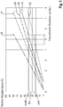
- Fig. 3 shows the compatibility bands 30 and 40 of the work machine 2 and the work device 3 in a common deceleration control pressure diagram.
- the compatibility band 30 of the work machine 2 and the compatibility band 40 of the work device 3 have an overlapping area 41.
- the braking system of the train 1 must be within this area Overlapping area 41 are operated to meet the legal requirements.
- Reference symbol 42 denotes an upper limit and reference symbol 43 denotes a lower limit of the compatibility band 40.
- the upper limit 42 describes the course for the implement 3 in the unloaded state.
- the lower limit 43 describes the course for the implement 3 in the loaded state.
- Reference numeral 44 denotes an operating point of the braking device 15 of the implement 3 in the loaded state, which is at the lower limit 43 of the compatibility band 40.
- Reference numeral 45 denotes an operating point of the braking device 12 of the work machine 2 in the unloaded state, which is at the upper limit 28 of the compatibility band 30.
- Fig. 4 shows an exemplary brake pressure characteristic curve 31 of the implement 3 of the train 1.
- the hydraulic brake pressure p h is used to control the braking device 15 of the implement 3.
- the pneumatically actuated braking device 15 of the work device is controlled with a pneumatic control pressure p p of 4.5 bar.
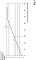
- Fig. 5 shows an example of a deceleration control pressure diagram of train 1.
- This shows a relative deceleration a rZ of train 1 via the pneumatic control pressure p p applied to the braking device 15 of the implement.
- Reference number 31 denotes an upper limit and reference number 32 denotes a lower limit of a compatibility band 33.
- the upper limit 31 describes the course for a train 1 in the loaded state with a minimum theoretical mass of the working machine 2.
- the lower limit 32 describes the course for a train 1 in the loaded state with a maximum theoretical mass of the working machine 2 Compatibility band 30 shown.
- the actual braking behavior is influenced by the actual mass of the agricultural work machine 2, which is not taken into account when the compatibility band 30 is established.
- a characteristic curve of the relative deceleration a zr of the train 1, which occurs when the braking system is activated is shown with reference numeral 34.
- a pneumatic control pressure p p of 4.5 bar is assumed when the brake system is activated.
- a target deceleration a rSoll of about 40% would be set.
- an actual deceleration a rIst which is less than the target deceleration a rSoll is achieved according to the curve 34 due to the occurrence of overrun operation.
- the overrun operation results from the fact that the braking force of the working machine 2 is greater than that of the working device, so that the working point of the braking system is outside the area 41 according to FIG Fig. 3 lies.
- a deviation 35 between the target deceleration a rSoll and the actual deceleration a rIst is compensated for by an adjustment, in the case shown by an increase, of the control pressure p p for controlling the braking device 15 of the working device 3.
- the adjustment of the control pressure p p is preferably carried out iteratively. Characteristic curves can be stored in the control and regulating device 18 in order to determine the target deceleration a rSoll .
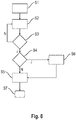
- Fig. 6 a simplified flow chart to illustrate the method for operating the braking system of the train 1 is shown.
- the activation of the brake system is detected in step S1.
- the activation can for example be determined by the sensor 20 on the basis of the actuation of the brake pedal 16.
- step S2 the target deceleration a rSoll and the actual deceleration a rIst are determined.
- the target deceleration a rSoll is determined by means of the characteristic curves stored in the control and regulating device 18.
- the hydraulic brake pressure p h generated by the braking device 12 of the work machine 2 can be detected by the pressure sensor 21.
- the pressure sensor 21 transmits the signals to the control and regulating device 18, which evaluates the signals from the sensor 21 in order to determine the actual delay a rIst therefrom.
- the pedal position of the brake pedal 16 or an actuation force exerted on the brake pedal 16 can be detected by the sensor 20 in order to determine the braking force generated by the braking device 12.
- the actual deceleration a rIst can be determined by the control and regulating device 18 as a function of the course of the driving speed during the braking process.
- the actual deceleration a rIst is determined on the basis of an acceleration during the braking process determined by the evaluation of position location signals provided by the position location sensor 25 and / or by means of the at least one acceleration sensor 22 arranged on the machine 2.
- the actual deceleration a rIst can be determined on the basis of forces occurring during the braking process on the coupling device 13 connecting the working machine 2 and the working device 3, which forces can be detected by the force transducer 26. Step according to the deceleration behavior of the at least one working device 3 after the activation of the brake system on the coupling device 13 tensile or compressive forces, which are detected by the force transducer 26 and transmitted to the control and regulating device 18 for evaluation.
- the actual deceleration can be determined by comparing the input speed and the output speed of the transmission 9, which are detected by sensors on the input shaft 8 or the output shaft 10.
- step S3 the actual deceleration a rIst is compared with the theoretical target deceleration a rSoll of train 1, which corresponds to the braking force generated. If the discrepancy 35 between the actual deceleration a rIst and the target deceleration a rSoll is equal to or greater than zero, the process returns to step S2. If the discrepancy 35 between the actual deceleration a rIst and the target deceleration a rSoll is less than zero, that is, if overrun operation is present, then the process goes to step S4.
- step S4 the deviation 35 between the actual deceleration a rIst and the target deceleration a rSoll is compared with a predeterminable limit value stored in the control and regulating device 18. If the predeterminable limit value of the deviation 35 is not found to be exceeded, the process goes to step S5.
- step S6 a branch is made to step S6, in which a notification signal is generated by the control and regulating device 18.
- Exceeding the predeterminable limit value of the deviation 35 between the target delay a rSoll and the actual delay a rIst can be evaluated as an indication of overloading of the train 1 or the wear on at least one of the braking devices 12, 15 of the train 1 and signaled accordingly.
- the notification signal After the notification signal has been generated in step S6, the process goes to step S5.
- step S5 the adjustment of the braking force generated by the braking device 15 of the at least one working device 3 takes place in order to compensate for the deviation 35.
- the control pressure pp of the braking device 15 of the implement 3 is adapted.
- the adaptation in step S5 is preferably carried out iteratively until the deviation 35 between the target deceleration a rSoll and the actual deceleration a rIst is essentially compensated.
- step S7 ends in step S7 when the braking process has been completed or is interrupted.
Applications Claiming Priority (1)
| Application Number | Priority Date | Filing Date | Title |
|---|---|---|---|
| DE102019120958.7A DE102019120958A1 (de) | 2019-08-02 | 2019-08-02 | Verfahren zum Betreiben eines Bremssystems eines landwirtschaftlichen Zuges |
Publications (2)
| Publication Number | Publication Date |
|---|---|
| EP3771601A1 true EP3771601A1 (fr) | 2021-02-03 |
| EP3771601B1 EP3771601B1 (fr) | 2023-03-08 |
Family
ID=70480066
Family Applications (1)
| Application Number | Title | Priority Date | Filing Date |
|---|---|---|---|
| EP20169557.4A Active EP3771601B1 (fr) | 2019-08-02 | 2020-04-15 | Procédé de fonctionnement d'un système de freinage d'un train agricole |
Country Status (2)
| Country | Link |
|---|---|
| EP (1) | EP3771601B1 (fr) |
| DE (1) | DE102019120958A1 (fr) |
Citations (5)
| Publication number | Priority date | Publication date | Assignee | Title |
|---|---|---|---|---|
| DE4429231C1 (de) * | 1994-08-18 | 1995-08-31 | Daimler Benz Ag | Verfahren zur lastabhängigen Bremsdruckregelung einer Fahrzeugkombination aus Zug- und Anhängefahrzeug |
| DE19519768C2 (de) | 1995-05-30 | 1997-05-28 | Knorr Bremse Systeme | Verfahren und Vorrichtung zum Einstellen der Bremskraft eines Anhängers eines aus einem Zugfahrzeug und mindestens einem Anhänger bestehenden Fahrzeugverbundes |
| DE102013007881A1 (de) | 2013-05-08 | 2014-11-13 | Knorr-Bremse Systeme für Nutzfahrzeuge GmbH | Verfahren zur Abbremsung einer Zugfahrzeug-Anhängerkombination mit reduzierter Anhängerbremskraft abhängig vom Ansprechen des Zugfahrzeug-ABS |
| EP3009312A1 (fr) * | 2014-10-13 | 2016-04-20 | Deere & Company | Procede de commande d'un systeme de freinage |
| DE102017011802A1 (de) * | 2017-12-20 | 2019-06-27 | Wabco Europe Bvba | Verfahren zur Stabilisierung einer Fahrzeugkombination |
Family Cites Families (13)
| Publication number | Priority date | Publication date | Assignee | Title |
|---|---|---|---|---|
| GB9703356D0 (en) | 1997-02-18 | 1997-04-09 | Lucas Ind Plc | Trailer brake control |
| DE10359039B4 (de) | 2003-12-17 | 2008-04-17 | Knorr-Bremse Systeme für Nutzfahrzeuge GmbH | Verfahren zum kupplungskraftabhängigen Korrigieren der Anhängerbremskraft und/oder der Zugfahrzeugbremskraft einer Zugfahrzeug-Anhängerkombination |
| JP5089881B2 (ja) | 2005-12-09 | 2012-12-05 | 住友ゴム工業株式会社 | 車両の荷重推定方法および装置、ならびに車両の荷重推定のためのプログラム |
| DE102006054703A1 (de) | 2006-06-27 | 2008-01-03 | Robert Bosch Gmbh | Verfahren und Steuergerät zur Erkennung eines Anhängerbetriebs bei einem Zugfahrzeug |
| DE102006036748A1 (de) | 2006-08-05 | 2008-02-07 | Wabco Gmbh | Elektrisch gesteuerte Bremsanlage |
| DE102009031851B4 (de) | 2009-07-03 | 2021-02-11 | Dipl. Ing. Tietjen Gmbh | Verfahren zur Abbremsung einer Zugfahrzeug-Anhänger-Kombination und Einrichtung |
| ITTO20110587A1 (it) | 2011-07-04 | 2013-01-05 | Cnh Italia Spa | Metodo e apparato per la frenatura di un trattore munito di un rimorchio |
| ITTO20110588A1 (it) | 2011-07-04 | 2013-01-05 | Cnh Italia Spa | Metodo e apparato per la frenatura di un trattore munito di un rimorchio |
| ITMO20120320A1 (it) | 2012-12-21 | 2014-06-21 | Cnh Italia Spa | Metodo ed apparato per controllare la frenatura di una combinazione trattore rimorchio. |
| DE102015006737A1 (de) | 2015-05-23 | 2016-11-24 | Wabco Gmbh | Verfahren und Vorrichtung zum elektronischen Regeln einer Fahrzeugverzögerung in einem ABS-Bremssystem |
| DE102015012378A1 (de) | 2015-09-21 | 2017-03-23 | Wabco Gmbh | Verfahren zum Einstellen von Bremsdrücken eines Kraftfahrzeugs, Bremsanlage zur Durchführung des Verfahrens sowie Kraftfahrzeug |
| DE102016104453A1 (de) | 2016-03-11 | 2017-09-14 | Claas Tractor Sas | Landwirtschaftlicher Zug mit einem Zugfahrzeug und Anhänger |
| DE102017202820A1 (de) | 2017-02-22 | 2018-08-23 | Robert Bosch Gmbh | Fahrzeugbremsanlage mit Blockierschutzregelung |
-
2019
- 2019-08-02 DE DE102019120958.7A patent/DE102019120958A1/de active Pending
-
2020
- 2020-04-15 EP EP20169557.4A patent/EP3771601B1/fr active Active
Patent Citations (5)
| Publication number | Priority date | Publication date | Assignee | Title |
|---|---|---|---|---|
| DE4429231C1 (de) * | 1994-08-18 | 1995-08-31 | Daimler Benz Ag | Verfahren zur lastabhängigen Bremsdruckregelung einer Fahrzeugkombination aus Zug- und Anhängefahrzeug |
| DE19519768C2 (de) | 1995-05-30 | 1997-05-28 | Knorr Bremse Systeme | Verfahren und Vorrichtung zum Einstellen der Bremskraft eines Anhängers eines aus einem Zugfahrzeug und mindestens einem Anhänger bestehenden Fahrzeugverbundes |
| DE102013007881A1 (de) | 2013-05-08 | 2014-11-13 | Knorr-Bremse Systeme für Nutzfahrzeuge GmbH | Verfahren zur Abbremsung einer Zugfahrzeug-Anhängerkombination mit reduzierter Anhängerbremskraft abhängig vom Ansprechen des Zugfahrzeug-ABS |
| EP3009312A1 (fr) * | 2014-10-13 | 2016-04-20 | Deere & Company | Procede de commande d'un systeme de freinage |
| DE102017011802A1 (de) * | 2017-12-20 | 2019-06-27 | Wabco Europe Bvba | Verfahren zur Stabilisierung einer Fahrzeugkombination |
Also Published As
| Publication number | Publication date |
|---|---|
| EP3771601B1 (fr) | 2023-03-08 |
| DE102019120958A1 (de) | 2021-02-04 |
Similar Documents
| Publication | Publication Date | Title |
|---|---|---|
| EP2269880B1 (fr) | Frein d'une combinaison véhicule de traction-remorque | |
| DE69833307T2 (de) | Anhängerbremsregelung | |
| EP3044053B1 (fr) | Procédé de stabilisation du comportement au roulage d'un attelage et dispositif de réglage d'une dynamique de roulage | |
| EP1818245A1 (fr) | Dispositif d'entraînement des roues et procédure pour un dispositif d'entraînement des roues | |
| EP2495123B1 (fr) | Procédé de commande pour un embrayage dans le flux d'entraînement d'un véhicule automobile | |
| EP0504913A1 (fr) | Réglage de pression de pneumatique | |
| DE102010019433A1 (de) | Verfahren zum Bremsen und Bremssystem eines fremdkraftgebremsten Gerätes | |
| DE102015012378A1 (de) | Verfahren zum Einstellen von Bremsdrücken eines Kraftfahrzeugs, Bremsanlage zur Durchführung des Verfahrens sowie Kraftfahrzeug | |
| EP2493732A1 (fr) | Système de freinage adaptatif pour remorque de charge | |
| DE102017205513A1 (de) | Verfahren und Vorrichtung zum Einstellen einer Betriebsstrategie für ein Fahrzeug | |
| EP3403894A2 (fr) | Procédé de détermination d'une force de soulèvement sur un véhicule utilitaire | |
| EP0827859B1 (fr) | Méthode et dispositif pour l'amélioration de la stabilité de conduite en décéleration | |
| EP3009312A1 (fr) | Procede de commande d'un systeme de freinage | |
| DE10232639A1 (de) | Lasttransport-Fahrzeug, insbesondere Gabelstapler | |
| DE102011117882A1 (de) | Ventilanordnung und Verfahren zur Steuerung einer Ventilanordnung | |
| EP3424788B1 (fr) | Véhicule de travail agricole | |
| EP3741604A1 (fr) | Procédé de régulation d'un dispositif de blocage d'au moins un engrenage compensateur | |
| EP3771601B1 (fr) | Procédé de fonctionnement d'un système de freinage d'un train agricole | |
| EP1473203B1 (fr) | véhicule remorqué utilisable sur route et hors route | |
| EP1680301B1 (fr) | Systeme de commande d'un vehicule | |
| EP3569458B1 (fr) | Procédé de fonctionnement d'un système de freinage d'un tracteur agricole, système de freinage pour un tracteur agricole ainsi que tracteur agricole | |
| DE102017214838A1 (de) | Verfahren zum Betreiben eines Antriebsstranges eines Kraftfahrzeugs | |
| DE10223296A1 (de) | Verfahren und Vorrichtung zur Steuerung von Fahrzeugen | |
| EP2653324B1 (fr) | Moissonneuse agricole | |
| DE102019205668A1 (de) | Verfahren zum Betreiben eines Antriebsstrangs |
Legal Events
| Date | Code | Title | Description |
|---|---|---|---|
| PUAI | Public reference made under article 153(3) epc to a published international application that has entered the european phase |
Free format text: ORIGINAL CODE: 0009012 |
|
| STAA | Information on the status of an ep patent application or granted ep patent |
Free format text: STATUS: THE APPLICATION HAS BEEN PUBLISHED |
|
| AK | Designated contracting states |
Kind code of ref document: A1 Designated state(s): AL AT BE BG CH CY CZ DE DK EE ES FI FR GB GR HR HU IE IS IT LI LT LU LV MC MK MT NL NO PL PT RO RS SE SI SK SM TR |
|
| AX | Request for extension of the european patent |
Extension state: BA ME |
|
| STAA | Information on the status of an ep patent application or granted ep patent |
Free format text: STATUS: REQUEST FOR EXAMINATION WAS MADE |
|
| 17P | Request for examination filed |
Effective date: 20210803 |
|
| RBV | Designated contracting states (corrected) |
Designated state(s): AL AT BE BG CH CY CZ DE DK EE ES FI FR GB GR HR HU IE IS IT LI LT LU LV MC MK MT NL NO PL PT RO RS SE SI SK SM TR |
|
| GRAP | Despatch of communication of intention to grant a patent |
Free format text: ORIGINAL CODE: EPIDOSNIGR1 |
|
| STAA | Information on the status of an ep patent application or granted ep patent |
Free format text: STATUS: GRANT OF PATENT IS INTENDED |
|
| INTG | Intention to grant announced |
Effective date: 20221028 |
|
| GRAS | Grant fee paid |
Free format text: ORIGINAL CODE: EPIDOSNIGR3 |
|
| GRAA | (expected) grant |
Free format text: ORIGINAL CODE: 0009210 |
|
| STAA | Information on the status of an ep patent application or granted ep patent |
Free format text: STATUS: THE PATENT HAS BEEN GRANTED |
|
| AK | Designated contracting states |
Kind code of ref document: B1 Designated state(s): AL AT BE BG CH CY CZ DE DK EE ES FI FR GB GR HR HU IE IS IT LI LT LU LV MC MK MT NL NO PL PT RO RS SE SI SK SM TR |
|
| REG | Reference to a national code |
Ref country code: CH Ref legal event code: EP Ref country code: AT Ref legal event code: REF Ref document number: 1552395 Country of ref document: AT Kind code of ref document: T Effective date: 20230315 |
|
| REG | Reference to a national code |
Ref country code: DE Ref legal event code: R096 Ref document number: 502020002661 Country of ref document: DE |
|
| REG | Reference to a national code |
Ref country code: IE Ref legal event code: FG4D Free format text: LANGUAGE OF EP DOCUMENT: GERMAN |
|
| P01 | Opt-out of the competence of the unified patent court (upc) registered |
Effective date: 20230516 |
|
| REG | Reference to a national code |
Ref country code: LT Ref legal event code: MG9D |
|
| REG | Reference to a national code |
Ref country code: NL Ref legal event code: MP Effective date: 20230308 |
|
| PG25 | Lapsed in a contracting state [announced via postgrant information from national office to epo] |
Ref country code: RS Free format text: LAPSE BECAUSE OF FAILURE TO SUBMIT A TRANSLATION OF THE DESCRIPTION OR TO PAY THE FEE WITHIN THE PRESCRIBED TIME-LIMIT Effective date: 20230308 Ref country code: NO Free format text: LAPSE BECAUSE OF FAILURE TO SUBMIT A TRANSLATION OF THE DESCRIPTION OR TO PAY THE FEE WITHIN THE PRESCRIBED TIME-LIMIT Effective date: 20230608 Ref country code: LV Free format text: LAPSE BECAUSE OF FAILURE TO SUBMIT A TRANSLATION OF THE DESCRIPTION OR TO PAY THE FEE WITHIN THE PRESCRIBED TIME-LIMIT Effective date: 20230308 Ref country code: LT Free format text: LAPSE BECAUSE OF FAILURE TO SUBMIT A TRANSLATION OF THE DESCRIPTION OR TO PAY THE FEE WITHIN THE PRESCRIBED TIME-LIMIT Effective date: 20230308 Ref country code: HR Free format text: LAPSE BECAUSE OF FAILURE TO SUBMIT A TRANSLATION OF THE DESCRIPTION OR TO PAY THE FEE WITHIN THE PRESCRIBED TIME-LIMIT Effective date: 20230308 Ref country code: ES Free format text: LAPSE BECAUSE OF FAILURE TO SUBMIT A TRANSLATION OF THE DESCRIPTION OR TO PAY THE FEE WITHIN THE PRESCRIBED TIME-LIMIT Effective date: 20230308 |
|
| PGFP | Annual fee paid to national office [announced via postgrant information from national office to epo] |
Ref country code: FR Payment date: 20230502 Year of fee payment: 4 Ref country code: DE Payment date: 20230420 Year of fee payment: 4 |
|
| PG25 | Lapsed in a contracting state [announced via postgrant information from national office to epo] |
Ref country code: SE Free format text: LAPSE BECAUSE OF FAILURE TO SUBMIT A TRANSLATION OF THE DESCRIPTION OR TO PAY THE FEE WITHIN THE PRESCRIBED TIME-LIMIT Effective date: 20230308 Ref country code: NL Free format text: LAPSE BECAUSE OF FAILURE TO SUBMIT A TRANSLATION OF THE DESCRIPTION OR TO PAY THE FEE WITHIN THE PRESCRIBED TIME-LIMIT Effective date: 20230308 Ref country code: GR Free format text: LAPSE BECAUSE OF FAILURE TO SUBMIT A TRANSLATION OF THE DESCRIPTION OR TO PAY THE FEE WITHIN THE PRESCRIBED TIME-LIMIT Effective date: 20230609 Ref country code: FI Free format text: LAPSE BECAUSE OF FAILURE TO SUBMIT A TRANSLATION OF THE DESCRIPTION OR TO PAY THE FEE WITHIN THE PRESCRIBED TIME-LIMIT Effective date: 20230308 |
|
| PG25 | Lapsed in a contracting state [announced via postgrant information from national office to epo] |
Ref country code: SM Free format text: LAPSE BECAUSE OF FAILURE TO SUBMIT A TRANSLATION OF THE DESCRIPTION OR TO PAY THE FEE WITHIN THE PRESCRIBED TIME-LIMIT Effective date: 20230308 Ref country code: RO Free format text: LAPSE BECAUSE OF FAILURE TO SUBMIT A TRANSLATION OF THE DESCRIPTION OR TO PAY THE FEE WITHIN THE PRESCRIBED TIME-LIMIT Effective date: 20230308 Ref country code: PT Free format text: LAPSE BECAUSE OF FAILURE TO SUBMIT A TRANSLATION OF THE DESCRIPTION OR TO PAY THE FEE WITHIN THE PRESCRIBED TIME-LIMIT Effective date: 20230710 Ref country code: EE Free format text: LAPSE BECAUSE OF FAILURE TO SUBMIT A TRANSLATION OF THE DESCRIPTION OR TO PAY THE FEE WITHIN THE PRESCRIBED TIME-LIMIT Effective date: 20230308 Ref country code: CZ Free format text: LAPSE BECAUSE OF FAILURE TO SUBMIT A TRANSLATION OF THE DESCRIPTION OR TO PAY THE FEE WITHIN THE PRESCRIBED TIME-LIMIT Effective date: 20230308 |
|
| PG25 | Lapsed in a contracting state [announced via postgrant information from national office to epo] |
Ref country code: SK Free format text: LAPSE BECAUSE OF FAILURE TO SUBMIT A TRANSLATION OF THE DESCRIPTION OR TO PAY THE FEE WITHIN THE PRESCRIBED TIME-LIMIT Effective date: 20230308 Ref country code: PL Free format text: LAPSE BECAUSE OF FAILURE TO SUBMIT A TRANSLATION OF THE DESCRIPTION OR TO PAY THE FEE WITHIN THE PRESCRIBED TIME-LIMIT Effective date: 20230308 Ref country code: IS Free format text: LAPSE BECAUSE OF FAILURE TO SUBMIT A TRANSLATION OF THE DESCRIPTION OR TO PAY THE FEE WITHIN THE PRESCRIBED TIME-LIMIT Effective date: 20230708 |
|
| REG | Reference to a national code |
Ref country code: CH Ref legal event code: PL |
|
| REG | Reference to a national code |
Ref country code: DE Ref legal event code: R026 Ref document number: 502020002661 Country of ref document: DE |
|
| PLBI | Opposition filed |
Free format text: ORIGINAL CODE: 0009260 |
|
| PLAX | Notice of opposition and request to file observation + time limit sent |
Free format text: ORIGINAL CODE: EPIDOSNOBS2 |
|
| PG25 | Lapsed in a contracting state [announced via postgrant information from national office to epo] |
Ref country code: LU Free format text: LAPSE BECAUSE OF NON-PAYMENT OF DUE FEES Effective date: 20230415 |
|
| 26 | Opposition filed |
Opponent name: ZF FRIEDRICHSHAFEN AG Effective date: 20231206 |
|
| REG | Reference to a national code |
Ref country code: BE Ref legal event code: MM Effective date: 20230430 |
|
| PG25 | Lapsed in a contracting state [announced via postgrant information from national office to epo] |
Ref country code: MC Free format text: LAPSE BECAUSE OF FAILURE TO SUBMIT A TRANSLATION OF THE DESCRIPTION OR TO PAY THE FEE WITHIN THE PRESCRIBED TIME-LIMIT Effective date: 20230308 |
|
| PG25 | Lapsed in a contracting state [announced via postgrant information from national office to epo] |
Ref country code: SI Free format text: LAPSE BECAUSE OF FAILURE TO SUBMIT A TRANSLATION OF THE DESCRIPTION OR TO PAY THE FEE WITHIN THE PRESCRIBED TIME-LIMIT Effective date: 20230308 Ref country code: MC Free format text: LAPSE BECAUSE OF FAILURE TO SUBMIT A TRANSLATION OF THE DESCRIPTION OR TO PAY THE FEE WITHIN THE PRESCRIBED TIME-LIMIT Effective date: 20230308 Ref country code: LI Free format text: LAPSE BECAUSE OF NON-PAYMENT OF DUE FEES Effective date: 20230430 Ref country code: DK Free format text: LAPSE BECAUSE OF FAILURE TO SUBMIT A TRANSLATION OF THE DESCRIPTION OR TO PAY THE FEE WITHIN THE PRESCRIBED TIME-LIMIT Effective date: 20230308 Ref country code: CH Free format text: LAPSE BECAUSE OF NON-PAYMENT OF DUE FEES Effective date: 20230430 |
|
| REG | Reference to a national code |
Ref country code: IE Ref legal event code: MM4A |
|
| PG25 | Lapsed in a contracting state [announced via postgrant information from national office to epo] |
Ref country code: BE Free format text: LAPSE BECAUSE OF NON-PAYMENT OF DUE FEES Effective date: 20230430 |
|
| PG25 | Lapsed in a contracting state [announced via postgrant information from national office to epo] |
Ref country code: IE Free format text: LAPSE BECAUSE OF NON-PAYMENT OF DUE FEES Effective date: 20230415 |
|
| PLBB | Reply of patent proprietor to notice(s) of opposition received |
Free format text: ORIGINAL CODE: EPIDOSNOBS3 |
|
| PG25 | Lapsed in a contracting state [announced via postgrant information from national office to epo] |
Ref country code: IE Free format text: LAPSE BECAUSE OF NON-PAYMENT OF DUE FEES Effective date: 20230415 |