EP3771318A1 - Landwirtschaftliches fahrzeuggespann - Google Patents
Landwirtschaftliches fahrzeuggespann Download PDFInfo
- Publication number
- EP3771318A1 EP3771318A1 EP20186889.0A EP20186889A EP3771318A1 EP 3771318 A1 EP3771318 A1 EP 3771318A1 EP 20186889 A EP20186889 A EP 20186889A EP 3771318 A1 EP3771318 A1 EP 3771318A1
- Authority
- EP
- European Patent Office
- Prior art keywords
- vehicle combination
- implement
- ground
- module
- traction module
- Prior art date
- Legal status (The legal status is an assumption and is not a legal conclusion. Google has not performed a legal analysis and makes no representation as to the accuracy of the status listed.)
- Granted
Links
Images
Classifications
-
- A—HUMAN NECESSITIES
- A01—AGRICULTURE; FORESTRY; ANIMAL HUSBANDRY; HUNTING; TRAPPING; FISHING
- A01B—SOIL WORKING IN AGRICULTURE OR FORESTRY; PARTS, DETAILS, OR ACCESSORIES OF AGRICULTURAL MACHINES OR IMPLEMENTS, IN GENERAL
- A01B59/00—Devices specially adapted for connection between animals or tractors and agricultural machines or implements
- A01B59/04—Devices specially adapted for connection between animals or tractors and agricultural machines or implements for machines pulled or pushed by a tractor
- A01B59/041—Devices specially adapted for connection between animals or tractors and agricultural machines or implements for machines pulled or pushed by a tractor preventing or limiting side-play of implements
-
- A—HUMAN NECESSITIES
- A01—AGRICULTURE; FORESTRY; ANIMAL HUSBANDRY; HUNTING; TRAPPING; FISHING
- A01B—SOIL WORKING IN AGRICULTURE OR FORESTRY; PARTS, DETAILS, OR ACCESSORIES OF AGRICULTURAL MACHINES OR IMPLEMENTS, IN GENERAL
- A01B73/00—Means or arrangements to facilitate transportation of agricultural machines or implements, e.g. folding frames to reduce overall width
- A01B73/02—Folding frames
- A01B73/04—Folding frames foldable about a horizontal axis
- A01B73/044—Folding frames foldable about a horizontal axis the axis being oriented in a longitudinal direction
-
- A—HUMAN NECESSITIES
- A01—AGRICULTURE; FORESTRY; ANIMAL HUSBANDRY; HUNTING; TRAPPING; FISHING
- A01B—SOIL WORKING IN AGRICULTURE OR FORESTRY; PARTS, DETAILS, OR ACCESSORIES OF AGRICULTURAL MACHINES OR IMPLEMENTS, IN GENERAL
- A01B59/00—Devices specially adapted for connection between animals or tractors and agricultural machines or implements
- A01B59/04—Devices specially adapted for connection between animals or tractors and agricultural machines or implements for machines pulled or pushed by a tractor
- A01B59/042—Devices specially adapted for connection between animals or tractors and agricultural machines or implements for machines pulled or pushed by a tractor having pulling means arranged on the rear part of the tractor
- A01B59/043—Devices specially adapted for connection between animals or tractors and agricultural machines or implements for machines pulled or pushed by a tractor having pulling means arranged on the rear part of the tractor supported at three points, e.g. by quick-release couplings
-
- A—HUMAN NECESSITIES
- A01—AGRICULTURE; FORESTRY; ANIMAL HUSBANDRY; HUNTING; TRAPPING; FISHING
- A01B—SOIL WORKING IN AGRICULTURE OR FORESTRY; PARTS, DETAILS, OR ACCESSORIES OF AGRICULTURAL MACHINES OR IMPLEMENTS, IN GENERAL
- A01B21/00—Harrows with rotary non-driven tools
- A01B21/02—Harrows with rotary non-driven tools with tooth-like tools
- A01B21/04—Harrows with rotary non-driven tools with tooth-like tools on horizontally-arranged axles
-
- A—HUMAN NECESSITIES
- A01—AGRICULTURE; FORESTRY; ANIMAL HUSBANDRY; HUNTING; TRAPPING; FISHING
- A01B—SOIL WORKING IN AGRICULTURE OR FORESTRY; PARTS, DETAILS, OR ACCESSORIES OF AGRICULTURAL MACHINES OR IMPLEMENTS, IN GENERAL
- A01B29/00—Rollers
- A01B29/02—Rollers with smooth surface
-
- A—HUMAN NECESSITIES
- A01—AGRICULTURE; FORESTRY; ANIMAL HUSBANDRY; HUNTING; TRAPPING; FISHING
- A01B—SOIL WORKING IN AGRICULTURE OR FORESTRY; PARTS, DETAILS, OR ACCESSORIES OF AGRICULTURAL MACHINES OR IMPLEMENTS, IN GENERAL
- A01B49/00—Combined machines
- A01B49/02—Combined machines with two or more soil-working tools of different kind
- A01B49/027—Combined machines with two or more soil-working tools of different kind with a rotating, soil working support element, e.g. a roller
-
- A—HUMAN NECESSITIES
- A01—AGRICULTURE; FORESTRY; ANIMAL HUSBANDRY; HUNTING; TRAPPING; FISHING
- A01B—SOIL WORKING IN AGRICULTURE OR FORESTRY; PARTS, DETAILS, OR ACCESSORIES OF AGRICULTURAL MACHINES OR IMPLEMENTS, IN GENERAL
- A01B63/00—Lifting or adjusting devices or arrangements for agricultural machines or implements
- A01B63/002—Devices for adjusting or regulating the position of tools or wheels
- A01B63/008—Vertical adjustment of tools
-
- A—HUMAN NECESSITIES
- A01—AGRICULTURE; FORESTRY; ANIMAL HUSBANDRY; HUNTING; TRAPPING; FISHING
- A01B—SOIL WORKING IN AGRICULTURE OR FORESTRY; PARTS, DETAILS, OR ACCESSORIES OF AGRICULTURAL MACHINES OR IMPLEMENTS, IN GENERAL
- A01B63/00—Lifting or adjusting devices or arrangements for agricultural machines or implements
- A01B63/14—Lifting or adjusting devices or arrangements for agricultural machines or implements for implements drawn by animals or tractors
- A01B63/24—Tools or tool-holders adjustable relatively to the frame
- A01B63/32—Tools or tool-holders adjustable relatively to the frame operated by hydraulic or pneumatic means without automatic control
-
- A—HUMAN NECESSITIES
- A01—AGRICULTURE; FORESTRY; ANIMAL HUSBANDRY; HUNTING; TRAPPING; FISHING
- A01B—SOIL WORKING IN AGRICULTURE OR FORESTRY; PARTS, DETAILS, OR ACCESSORIES OF AGRICULTURAL MACHINES OR IMPLEMENTS, IN GENERAL
- A01B69/00—Steering of agricultural machines or implements; Guiding agricultural machines or implements on a desired track
- A01B69/003—Steering or guiding of machines or implements pushed or pulled by or mounted on agricultural vehicles such as tractors, e.g. by lateral shifting of the towing connection
- A01B69/004—Steering or guiding of machines or implements pushed or pulled by or mounted on agricultural vehicles such as tractors, e.g. by lateral shifting of the towing connection automatic
Definitions
- the invention relates to an agricultural vehicle combination consisting of a traction module designed as an equipment carrier with a ground-engaging drive element and an implement attached to the traction module by means of a coupling device.
- Such an agricultural vehicle combination with a fully electric implement carrier with caterpillar drive is offered by Aebi under the designation EC 170/130, for example.
- a portal cutter bar or a trailer can be attached to the equipment carrier. Due to its compact and manoeuvrable design, the equipment carrier is primarily suitable for special tasks such as working on smaller meadows in mountainous terrain or on steep slopes in viticulture.
- the agricultural vehicle combination comprises a pulling module designed as a device carrier with a ground-engaging drive element and a working device attached to the pulling module by means of a coupling device with a folding axis supporting the working device at least during transport operation against the ground.
- the coupling device has a turntable for providing a degree of freedom of rotation between the traction module and the implement along a Longitudinal axis of the implement and a swivel joint for providing a degree of swivel freedom between the traction module and the implement along a vertical axis of the traction module, the swivel joint being adjustable with respect to its swivel angle to influence the direction of travel of the vehicle combination by means of a steering actuator.
- the coupling device is typically located in the rear area of the traction module, so that the drive element takes on the function of a driven front axle and the folding axle, at least during transport, the function of a rear axle of the vehicle combination in contact with the ground.
- the folding axis is brought into a position remote from the ground, so that the implement is supported on the field surface to be worked via work tools provided for field cultivation and / or associated guide wheels.
- a working device in the form of a harrow, the working tools of which, designed as harrow disks or trailing rollers, rest on or engage in the field surface to be worked.
- the work device is equipped with driven work tools
- the implement can then be, for example, a rotary swather, a row sowing unit or the like.
- the agricultural vehicle combination can be part of a vehicle fleet consisting of a large number of individual vehicle combinations. There is the possibility that these are operated without a driver and therefore have a corresponding autonomous vehicle control.
- the ground-engaging drive element is preferably a single wheel or caterpillar drive.
- the use of a single-axis drive leads to particularly good maneuverability of the train module and thus of the vehicle combination.
- the ground-engaging drive element can be operated electrically.
- the electrical energy is supplied in particular via a cable section that can be connected to a power supply vehicle.
- a cable route for a vehicle fleet consisting of a large number of individual vehicle combinations is shown, for example, in FIG DE 10 2019 202 826 A1 shown. Notwithstanding this, each of the vehicle combinations can also have its own power supply.
- the pull module is equipped with a hydrogen-fed fuel cell or an accumulator. It is also possible instead of an electric drive to provide a diesel-powered internal combustion engine of conventional design.
- the steering actuator is in particular formed by at least one steering cylinder which, for adjusting the pivot angle, runs between a support structure of the traction module and a base plate of the pivot joint connected to the slewing ring.
- the steering cylinder can be controlled hydraulically, but electro-hydraulic or electric motor actuation can also be provided.
- the work device has a device for adjusting the height of work tools provided for field cultivation.
- the device for height adjustment is formed, for example, by a parallelogram linkage which can be actuated by means of a hydraulic cylinder and which allows parallel adjustment of the working tools perpendicular to a field surface to be worked.
- the implement can have a device for pivoting the folding axis from a lower position intended for transport operation into an upper position intended for field operation, in which work tools intended for field cultivation are brought into contact with the ground.
- the device for pivoting the folding axis can comprise a hydraulic cylinder running between a supporting structure of the working device and an articulation point of the folding axis.
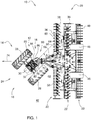
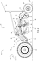
- Fig. 1 shows an embodiment of an agricultural vehicle combination according to the invention, which is shown below with simultaneous reference to FIG Fig. 2 is described.
- the vehicle combination 10 comprises a pulling module 14 in the form of a device carrier 12 with a ground-engaging drive element 16 and a working device 20 with working tools 22 provided for field cultivation attached to the pulling module 14 by means of a coupling device 18.
- the ground-engaging drive element 16 is a single wheel drive 24 with left and right drive wheels 26, 28, which are electrically operated by means of an electric motor 30 via an interposed differential gear 32.
- the electrical energy is supplied via a cable section 34 that can be connected to a power supply vehicle.
- the cable section 34 including the power supply vehicle is not explicitly shown, but further details can be found in FIG DE 10 2019 202 826 A1 in the case of a vehicle fleet consisting of a large number of individual vehicle combinations 10. These are operated without a driver and have a corresponding autonomous vehicle control.
- the ground-engaging drive element 16 can be designed as a single caterpillar drive.
- the caterpillar drive comprises a rubber chain mounted by means of a plurality of tensioning, guide or drive rollers on each of the two sides of the tension module 14.
- the implement 20 is a harrow 36 with work tools 22 designed as harrow disks 38 or trailing rollers 40, which rest on or engage in a field surface 42 to be worked.
- a folding axle 44 with left and right wheels 46, 48.
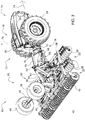
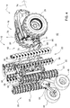
- a device 50 for pivoting the folding axle 44 allows it to be moved from a lower position provided for transport operation Fig. 3 , in which the folding axis 44 supports the implement 20 relative to the ground, in an upper position provided for field operation according to FIG Fig. 4 to pivot in which at the same time the associated work tools 22 are brought into contact with the ground.
- the folding axle 44 is pivoted back in the opposite direction.
- the device 50 for pivoting the folding axis 44 comprises a hydraulic cylinder 56 running between a supporting structure 52 of the working device 20 and a pivot point 54 of the folding axis 44.
- the work tools 22 are arranged distributed along the left and right arms 58, 60 and can be moved into an upright position provided for the transport operation by means of associated hydraulic cylinders 62, 64 Fig. 4 spend.
- the implement 20 has an in Fig. 2 Device 66 to be recognized for adjusting the height of the work tools 22.
- the device 66 for height adjustment is formed by a parallelogram linkage 70 which can be actuated by means of a further hydraulic cylinder 68 and which allows parallel adjustment of the working tools 22 perpendicular to the field surface 42 to be worked.
- the coupling device 18 provided between the pulling module 14 and the work device 20 has a turntable 72 to provide a degree of freedom of rotation between the pulling module 14 and the work device 20 along a longitudinal or roll axis 74 of the work device 20 and a swivel joint 76 to provide a degree of swivel freedom between the pulling module 14 and the working device 20 along a vertical axis 78 of the pulling module 14.
- the swivel joint 76 is used to influence the direction of travel of the vehicle combination 10 adjustable by means of a steering actuator 80 with respect to its pivot angle ⁇ .
- the steering actuator 80 is formed by left and right steering cylinders 82, 84, which run between a support structure 86 of the tension module 14 and a base plate 88 of the swivel joint 76 connected to the turntable 72 to adjust the swivel angle ⁇ .
- the two steering cylinders 82, 84 are controlled hydraulically.
- the coupling device 18 is located in the rear area 90 of the traction module 14, so that the drive element 16 assumes the function of a driven front axle and the folding axle 44 assumes the function of a rear axle of the vehicle combination 10 in contact with the ground, at least during transport.
- the folding axle 44 is brought into a position remote from the ground, so that the implement 20 is supported on the field surface 42 to be processed via its work tools 22 and / or associated guide wheels (not shown).
- the work device 20 is equipped with driven work tools 22, these can be brought into connection with a power take-off of the pulling module 14 via a power take-off shaft passed through the turntable 72 of the coupling device 18.
- the implement 20 can then be, for example, a rotary swather, a row sowing unit or the like.
Landscapes
- Life Sciences & Earth Sciences (AREA)
- Engineering & Computer Science (AREA)
- Mechanical Engineering (AREA)
- Soil Sciences (AREA)
- Environmental Sciences (AREA)
- Zoology (AREA)
- Agricultural Machines (AREA)
Abstract
Description
- Die Erfindung betrifft ein landwirtschaftliches Fahrzeuggespann, bestehend aus einem als Geräteträger ausgebildeten Zugmodul mit einem bodeneingreifenden Antriebselement und einem an dem Zugmodul mittels einer Kupplungseinrichtung angebrachten Arbeitsgerät.
- Ein derartiges landwirtschaftliches Fahrzeuggespann mit einem vollelektrischen Geräteträger mit Raupenantrieb wird beispielsweise von Aebi unter der Bezeichnung EC 170/130 angeboten. An dem Geräteträger lässt sich unter anderem ein Portalmähbalken oder ein Anhänger anbringen. Aufgrund seiner kompakten und wendigen Bauweise eignet sich der Geräteträger in erster Linie für Spezialaufgaben wie die Bearbeitung kleinerer Wiesenflächen in bergigem Terrain oder von Steillagen im Weinanbau.
- Es ist Aufgabe der vorliegenden Erfindung, ein landwirtschaftliches Fahrzeuggespann der eingangs genannten Art im Sinne universeller Einsatzmöglichkeiten weiterzubilden.
- Diese Aufgabe wird durch ein landwirtschaftliches Fahrzeuggespann mit den Merkmalen des Patentanspruchs 1 gelöst.
- Das landwirtschaftliche Fahrzeuggespann umfasst ein als Geräteträger ausgebildetes Zugmodul mit einem bodeneingreifenden Antriebselement und einem an dem Zugmodul mittels einer Kupplungseinrichtung angebrachten Arbeitsgerät mit einer das Arbeitsgerät zumindest während eines Transportbetriebs gegenüber dem Erdboden abstützenden Klappachse. Die Kupplungseinrichtung weist einen Drehkranz zur Bereitstellung eines Drehfreiheitsgrads zwischen dem Zugmodul und dem Arbeitsgerät entlang einer Längsachse des Arbeitsgeräts und ein Schwenkgelenk zur Bereitstellung eines Schwenkfreiheitsgrads zwischen dem Zugmodul und dem Arbeitsgerät entlang einer Hochachse des Zugmoduls auf, wobei das Schwenkgelenk zur Beeinflussung der Fahrtrichtung des Fahrzeuggespanns mittels eines Lenkaktuators bezüglich seines Schwenkeinschlags verstellbar ist.
- Die mittels der Kupplungseinrichtung geschaffene flexible Anbindung des Arbeitsgeräts an das Zugmodul wie auch die insofern vorgesehene Integration einer durch das Schwenkgelenk gebildeten Knicklenkung führt zu einem besonders agilen Fahrverhalten des Fahrzeuggespanns selbst in hügeligem Terrain und bei Verwendung vergleichsweise schwerer bzw. groß dimensionierter Arbeitsgeräte. Dies ermöglicht nicht nur einen universellen Einsatz des Fahrzeuggespanns, sondern bewahrt zugleich die Vorteile gängiger Geräteträgerkonzepte hinsichtlich Flexibilität und Agilität.
- Die Kupplungseinrichtung befindet sich typischerweise im Heckbereich des Zugmoduls, sodass das Antriebselement die Funktion einer angetriebenen Vorderachse und die Klappachse zumindest während des Transportbetriebs die Funktion einer mit dem Boden in Kontakt stehenden Hinterachse des Fahrzeuggespanns übernimmt. Während des Feldbetriebs wird die Klappachse in eine bodenferne Position verbracht, sodass sich das Arbeitsgerät über zur Feldbearbeitung vorgesehene Arbeitswerkzeuge und/oder zugehörige Führungsräder auf der zu bearbeitenden Feldoberfläche abstützt. Beispielhaft sei hier ein Arbeitsgerät in Gestalt einer Egge genannt, deren als Eggenscheiben bzw. Nachläuferwalzen ausgebildete Arbeitswerkzeuge auf der zu bearbeitende Feldoberfläche aufliegen bzw. in diese eingreifen. Für den Fall, dass das Arbeitsgerät mit angetriebenen Arbeitswerkzeugen ausgerüstet ist, ist es denkbar, diese über eine durch den Drehkranz der Kupplungseinrichtung hindurchgeführte Zapfwelle mit einem Nebenabtrieb des Zugmoduls zu verbinden. Bei dem Arbeitsgerät kann es sich dann zum Beispiel um einen Kreiselschwader, eine Reihensäeinheit oder dergleichen handeln.
- Das landwirtschaftliche Fahrzeuggespann kann Bestandteil einer aus einer Vielzahl einzelner Fahrzeuggespanne bestehenden Fahrzeugflotte sein. Dabei besteht die Möglichkeit, dass diese fahrerlos betrieben werden, mithin über eine entsprechende autonome Fahrzeugsteuerung verfügen.
- Vorteilhafte Weiterbildungen des erfindungsgemäßen Fahrzeuggespanns gehen aus den Unteransprüchen hervor.
- Vorzugsweise handelt es sich bei dem bodeneingreifenden Antriebselement um einen einzelnen Rad- oder Raupenantrieb. Die Verwendung eines einachsigen Antriebs führt zu einer besonders guten Wendigkeit des Zugmoduls und damit des Fahrzeuggespanns.
- Das bodeneingreifende Antriebselement kann elektrisch betrieben sein. Die Zuführung der elektrischen Energie erfolgt insbesondere über eine an einem Stromversorgungsfahrzeug anschließbare Kabelstrecke. Eine mögliche Ausführungsform einer derartigen Kabelstrecke für eine aus einer Vielzahl einzelner Fahrzeuggespanne bestehende Fahrzeugflotte ist zum Beispiel in der
DE 10 2019 202 826 A1 gezeigt. Abweichend davon kann jedes der Fahrzeuggespanne auch über eine eigene Stromversorgung verfügen. Hierzu ist das Zugmodul mit einer wasserstoffgespeisten Brennstoffzelle oder einem Akkumulator ausgestattet. Ferner ist es möglich, anstelle eines elektrischen Antriebs einen dieselbetriebenen Verbrennungsmotor konventioneller Bauart vorzusehen. - Der Lenkaktuator ist insbesondere durch wenigstens einen Lenkzylinder gebildet, der zur Verstellung des Schwenkeinschlags zwischen einer Tragestruktur des Zugmoduls und einer mit dem Drehkranz verbundenen Basisplatte des Schwenkgelenks verläuft. Die Ansteuerung des Lenkzylinders kann hydraulisch erfolgen, es kann jedoch auch eine elektrohydraulische oder elektromotorische Betätigung vorgesehen sein.
- Zusätzlich besteht die Möglichkeit, dass das Arbeitsgerät eine Vorrichtung zur Höhenverstellung von zur Feldbearbeitung vorgesehenen Arbeitswerkzeugen aufweist. Die Vorrichtung zur Höhenverstellung ist beispielsweise durch ein mittels eines Hydraulikzylinders betätigbares Parallelogrammgestänge gebildet, das eine Parallelverstellung der Arbeitswerkzeuge senkrecht zu einer zu bearbeitenden Feldoberfläche erlaubt.
- Daneben kann das Arbeitsgerät eine Vorrichtung zum Verschwenken der Klappachse von einer für den Transportbetrieb vorgesehenen unteren Stellung in eine für den Feldbetrieb vorgesehene obere Stellung aufweisen, in der zugleich zur Feldbearbeitung vorgesehene Arbeitswerkzeuge in Bodenkontakt gebracht werden. Zum Ausheben des Arbeitsgeräts bzw. vor Aufnahme des Transportbetriebs wird die Klappachse in der umgekehrten Richtung zurückgeschwenkt. Die Vorrichtung zum Verschwenken der Klappachse kann einen zwischen einer tragenden Struktur des Arbeitsgeräts und einer Anlenkstelle der Klappachse verlaufenden Hydraulikzylinder umfassen.
- Das erfindungsgemäße landwirtschaftliche Fahrzeuggespann wird im Folgenden anhand der beigefügten Zeichnungen näher erläutert. Hierbei bezeichnen übereinstimmende Bezugszeichen baulich identische oder bezüglich ihrer Funktion vergleichbare Komponenten. Es zeigen:
- Fig. 1
- ein Ausführungsbeispiel eines erfindungsgemäßen landwirtschaftlichen Fahrzeuggespanns mit einem als Geräteträger ausgebildeten Zugmodul sowie einem daran angebrachten Arbeitsgerät in Aufsichtsdarstellung,
- Fig. 2
- eine Seitendarstellung des in
Fig. 1 wiedergegebenen landwirtschaftlichen Fahrzeuggespanns, - Fig. 3
- eine perspektivische Darstellung des in
Fig. 1 wiedergegebenen landwirtschaftlichen Fahrzeuggespanns während eines Transportbetriebs, und - Fig. 4
- eine perspektivische Darstellung des in
Fig. 1 wiedergegebenen landwirtschaftlichen Fahrzeuggespanns während eines Feldbetriebs. -
Fig. 1 zeigt ein Ausführungsbeispiel eines erfindungsgemäßen landwirtschaftlichen Fahrzeuggespanns, das nachfolgend unter gleichzeitiger Bezugnahme aufFig. 2 beschrieben wird. - Das Fahrzeuggespann 10 umfasst ein als Geräteträger 12 ausgebildetes Zugmodul 14 mit einem bodeneingreifenden Antriebselement 16 und einem an dem Zugmodul 14 mittels einer Kupplungseinrichtung 18 angebrachten Arbeitsgerät 20 mit zur Feldbearbeitung vorgesehenen Arbeitswerkzeugen 22.
- Bei dem bodeneingreifenden Antriebselement 16 handelt es sich um einen einzelnen Radantrieb 24 mit linken und rechten Antriebsrädern 26, 28, die mittels eines Elektromotors 30 über ein zwischengeschaltetes Differentialgetriebe 32 elektrisch betrieben werden. Die Zuführung der elektrischen Energie erfolgt über eine an einem Stromversorgungsfahrzeug anschließbare Kabelstrecke 34. Die Kabelstrecke 34 einschließlich des Stromversorgungsfahrzeugs ist nicht explizit dargestellt, weitere Einzelheiten lassen sich jedoch aus der
DE 10 2019 202 826 A1 für den Fall einer aus einer Vielzahl einzelner Fahrzeuggespanne 10 bestehenden Fahrzeugflotte entnehmen. Diese werden fahrerlos betrieben und verfügen über eine entsprechende autonome Fahrzeugsteuerung. - Alternativ kann das bodeneingreifende Antriebselement 16 als einzelner Raupenantrieb ausgebildet sein. Der Raupenantrieb umfasst in diesem Fall auf jeder der beiden Seiten des Zugmoduls 14 eine mittels mehrerer Spann-, Leit- bzw. Antriebsrollen gelagerte Gummilaufkette.
- Beispielsgemäß handelt es sich bei dem Arbeitsgerät 20 um eine Egge 36 mit als Eggenscheiben 38 bzw. Nachläuferwalzen 40 ausgebildeten Arbeitswerkzeugen 22, die auf einer zu bearbeitenden Feldoberfläche 42 aufliegen bzw. in diese eingreifen.
- Im Heckbereich des Arbeitsgeräts 20 befindet sich eine Klappachse 44 mit linken und rechten Rädern 46, 48. Eine Vorrichtung 50 zum Verschwenken der Klappachse 44 erlaubt es, diese von einer für den Transportbetrieb vorgesehenen unteren Stellung gemäß
Fig. 3 , in der die Klappachse 44 das Arbeitsgerät 20 gegenüber dem Erdboden abstützt, in eine für einen Feldbetrieb vorgesehene obere Stellung gemäßFig. 4 zu verschwenken, in der zugleich die zugehörigen Arbeitswerkzeuge 22 in Bodenkontakt gebracht werden. Zum Ausheben des Arbeitsgeräts 20 bzw. vor Aufnahme des Transportbetriebs wird die Klappachse 44 in der umgekehrten Richtung zurückgeschwenkt. Wie sichFig. 2 entnehmen lässt, umfasst die Vorrichtung 50 zum Verschwenken der Klappachse 44 einen zwischen einer tragenden Struktur 52 des Arbeitsgeräts 20 und einer Anlenkstelle 54 der Klappachse 44 verlaufenden Hydraulikzylinder 56. - Beispielsgemäß sind die Arbeitswerkzeuge 22 entlang linker und rechter Ausleger 58, 60 verteilt angeordnet und lassen sich mittels zugehöriger Hydraulikzylinder 62, 64 in eine für den Transportbetrieb vorgesehene aufrechte Position gemäß
Fig. 4 verbringen. - Ferner weist das Arbeitsgerät 20 eine in
Fig. 2 zu erkennende Vorrichtung 66 zur Höhenverstellung der Arbeitswerkzeuge 22 auf. Die Vorrichtung 66 zur Höhenverstellung ist durch ein mittels eines weiteren Hydraulikzylinders 68 betätigbares Parallelogrammgestänge 70 gebildet, das eine Parallelverstellung der Arbeitswerkzeuge 22 senkrecht zur zu bearbeitenden Feldoberfläche 42 erlaubt. - Die zwischen Zugmodul 14 und Arbeitsgerät 20 vorgesehene Kupplungseinrichtung 18 weist einen Drehkranz 72 zur Bereitstellung eines Drehfreiheitsgrads zwischen dem Zugmodul 14 und dem Arbeitsgerät 20 entlang einer Längs- bzw. Wankachse 74 des Arbeitsgeräts 20 und ein Schwenkgelenk 76 zur Bereitstellung eines Schwenkfreiheitsgrads zwischen dem Zugmodul 14 und dem Arbeitsgerät 20 entlang einer Hochachse 78 des Zugmoduls 14 auf. Das Schwenkgelenk 76 ist zur Beeinflussung der Fahrtrichtung des Fahrzeuggespanns 10 mittels eines Lenkaktuators 80 bezüglich seines Schwenkeinschlags δ verstellbar. Der Lenkaktuator 80 ist durch linke und rechte Lenkzylinder 82, 84 gebildet, die zur Verstellung des Schwenkeinschlags δ zwischen einer Tragstruktur 86 des Zugmoduls 14 und einer mit dem Drehkranz 72 verbundenen Basisplatte 88 des Schwenkgelenks 76 verlaufen. Die Ansteuerung der beiden Lenkzylinder 82, 84 erfolgt hydraulisch.
- Die Kupplungseinrichtung 18 befindet sich im vorliegenden Fall im Heckbereich 90 des Zugmoduls 14, sodass das Antriebselement 16 die Funktion einer angetriebenen Vorderachse und die Klappachse 44 zumindest während des Transportbetriebs die Funktion einer mit dem Boden in Kontakt stehenden Hinterachse des Fahrzeuggespanns 10 übernimmt. Im Feldbetrieb wird die Klappachse 44 in eine bodenferne Position verbracht, sodass sich das Arbeitsgerät 20 über seine Arbeitswerkzeuge 22 und/oder zugehörige (nicht dargestellte) Führungsräder auf der zu bearbeitenden Feldoberfläche 42 abstützt.
- Für den Fall, dass das Arbeitsgerät 20 mit angetriebenen Arbeitswerkzeugen 22 ausgerüstet ist, lassen sich diese über eine durch den Drehkranz 72 der Kupplungseinrichtung 18 hindurchgeführte Zapfwelle mit einem Nebenabtrieb des Zugmoduls 14 in Verbindung bringen. Bei dem Arbeitsgerät 20 kann es sich dann zum Beispiel um einen Kreiselschwader, eine Reihensäeinheit oder dergleichen handeln.
- Die mittels der Kupplungseinrichtung 18 geschaffene flexible Anbindung des Arbeitsgeräts 20 an das Zugmodul 14 wie auch die insofern vorgesehene Integration einer durch das Schwenkgelenk 76 gebildeten Knicklenkung führt zu einem besonders agilen Fahrverhalten des Fahrzeuggespanns 10 selbst in hügeligem Terrain und bei Verwendung vergleichsweise schwerer bzw. groß dimensionierter Arbeitsgeräte 20.
Claims (7)
- Landwirtschaftliches Fahrzeuggespann, umfassend ein als Geräteträger (12) ausgebildetes Zugmodul (14) mit einem bodeneingreifenden Antriebselement (16) und ein an dem Zugmodul (14) mittels einer Kupplungseinrichtung (18) angebrachtes Arbeitsgerät (20) mit einer das Arbeitsgerät (20) zumindest während eines Transportbetriebs gegenüber dem Erdboden abstützenden Klappachse (44), wobei die Kupplungseinrichtung (18) einen Drehkranz (72) zur Bereitstellung eines Drehfreiheitsgrads zwischen dem Zugmodul (14) und dem Arbeitsgerät (20) entlang einer Längsachse (74) des Arbeitsgeräts (20) und ein Schwenkgelenk (76) zur Bereitstellung eines Schwenkfreiheitsgrads zwischen dem Zugmodul (14) und dem Arbeitsgerät (20) entlang einer Hochachse (78) des Zugmoduls (14) aufweist, wobei das Schwenkgelenk (76) zur Beeinflussung der Fahrtrichtung des Fahrzeuggespanns (10) mittels eines Lenkaktuators (80) bezüglich seines Schwenkeinschlags (δ) verstellbar ist.
- Fahrzeuggespann nach Anspruch 1, dadurch gekennzeichnet, dass es sich bei dem bodeneingreifenden Antriebselement (16) um einen einzelnen Rad- oder Raupenantrieb (24) handelt.
- Fahrzeuggespann nach Anspruch 1 oder 2, dadurch gekennzeichnet, dass das bodeneingreifende Antriebselement (16) elektrisch betrieben ist.
- Fahrzeuggespann nach wenigstens einem der Ansprüche 1 bis 3, dadurch gekennzeichnet, dass der Lenkaktuator (80) durch wenigstens einen Lenkzylinder (82, 84) gebildet ist, der zur Verstellung des Schwenkeinschlags (δ) zwischen einer Tragestruktur (86) des Zugmoduls (14) und einer mit dem Drehkranz (72) verbundenen Basisplatte (88) des Schwenkgelenks (76) verläuft.
- Fahrzeuggespann nach wenigstens einem der Ansprüche 1 bis 4, dadurch gekennzeichnet, dass das Arbeitsgerät (20) eine Vorrichtung (66) zur Höhenverstellung von zur Feldbearbeitung vorgesehenen Arbeitswerkzeugen (22) aufweist.
- Fahrzeuggespann nach wenigstens einem der Ansprüche 1 bis 5, dadurch gekennzeichnet, dass das Arbeitsgerät (20) eine Vorrichtung (50) zum Verschwenken der Klappachse (44) von einer für den Transportbetrieb vorgesehenen unteren Stellung in eine für den Feldbetrieb vorgesehene obere Stellung aufweist, in der zugleich zur Feldbearbeitung vorgesehene Arbeitswerkzeuge (22) in Bodenkontakt gebracht werden.
- Fahrzeugflotte, bestehend aus einer Vielzahl einzelner Fahrzeuggespanne (10) nach wenigstens einem der Ansprüche 1 bis 6.
Applications Claiming Priority (1)
| Application Number | Priority Date | Filing Date | Title |
|---|---|---|---|
| DE102019211496.2A DE102019211496A1 (de) | 2019-08-01 | 2019-08-01 | Landwirtschaftliches Fahrzeuggespann |
Publications (2)
| Publication Number | Publication Date |
|---|---|
| EP3771318A1 true EP3771318A1 (de) | 2021-02-03 |
| EP3771318B1 EP3771318B1 (de) | 2022-03-09 |
Family
ID=71738043
Family Applications (1)
| Application Number | Title | Priority Date | Filing Date |
|---|---|---|---|
| EP20186889.0A Active EP3771318B1 (de) | 2019-08-01 | 2020-07-21 | Landwirtschaftliches fahrzeuggespann |
Country Status (3)
| Country | Link |
|---|---|
| US (1) | US11617297B2 (de) |
| EP (1) | EP3771318B1 (de) |
| DE (1) | DE102019211496A1 (de) |
Families Citing this family (11)
| Publication number | Priority date | Publication date | Assignee | Title |
|---|---|---|---|---|
| USD962998S1 (en) | 2019-03-18 | 2022-09-06 | Deere & Company | Hood for a work machine |
| USD939592S1 (en) | 2020-03-05 | 2021-12-28 | Deere & Company | Work machine |
| DE102020132836A1 (de) | 2020-12-09 | 2022-06-09 | Deere & Company | Landwirtschaftliches Fahrzeuggespann |
| DE202021103034U1 (de) | 2021-06-04 | 2022-09-06 | Horsch Maschinen Gmbh | Landwirtschaftliches Nutzfahrzeuggespann mit autonomer Zugmaschine |
| DE102021114420A1 (de) | 2021-06-04 | 2022-12-08 | Horsch Maschinen Gmbh | Landwirtschaftliches Nutzfahrzeuggespann mit autonomer Zugmaschine |
| DE102021129248A1 (de) | 2021-11-10 | 2023-05-11 | Horsch Maschinen Gmbh | Landwirtschaftliches Nutzfahrzeug mit verbesserter Lenkung |
| DE102021130011A1 (de) | 2021-11-17 | 2023-05-17 | Deere & Company | Selbstfahrende landwirtschaftliche Arbeitsmaschine |
| US12344251B2 (en) * | 2021-12-16 | 2025-07-01 | Deere & Company | Multi-selectable application mode steering system and method thereof |
| US12263896B2 (en) | 2021-12-16 | 2025-04-01 | Deere & Company | Multi-selectable application mode steering system and method thereof |
| DE102024106067A1 (de) * | 2024-03-01 | 2025-09-04 | Lemken Gmbh & Co. Kg | Landwirtschaftliche Arbeitsmaschine |
| DE102024128069A1 (de) * | 2024-09-27 | 2026-04-02 | Horsch Maschinen Gmbh | Landwirtschaftliche Arbeitsmaschine und landwirtschaftlicher Maschinenverbund |
Citations (5)
| Publication number | Priority date | Publication date | Assignee | Title |
|---|---|---|---|---|
| CN200938740Y (zh) * | 2006-08-29 | 2007-08-29 | 刘蕴辉 | 多用途农林作业机 |
| US20170355252A1 (en) * | 2016-06-10 | 2017-12-14 | Cnh Industrial America Llc | Removable panel on an autonomous work vehicle |
| EP3461676A1 (de) * | 2017-09-29 | 2019-04-03 | Deere & Company | Stromversorgungssystem für eine fahrzeugflotte |
| EP3702305A1 (de) * | 2019-03-01 | 2020-09-02 | Deere & Company | Spannvorrichtung für eine kabelgebundene energie- und/oder datenübertragungsstrecke |
| EP3712003A1 (de) * | 2019-03-18 | 2020-09-23 | Deere & Company | Stromversorgungssystem eines flottenfahrzeugs |
Family Cites Families (4)
| Publication number | Priority date | Publication date | Assignee | Title |
|---|---|---|---|---|
| US2777373A (en) * | 1952-10-31 | 1957-01-15 | Harry A Pursche | Two-way roll-over disc plow |
| US2900033A (en) * | 1955-10-21 | 1959-08-18 | Anthony R Coviello | Agricultural implement, particularly a reversible plow, and support vehicle therefor |
| US3087556A (en) * | 1956-02-09 | 1963-04-30 | Harry A Pursche | Two way plow construction with means to limit rotation of carrier |
| DE102018108024A1 (de) | 2018-04-05 | 2019-10-10 | Horsch Maschinen Gmbh | Autonomes landwirtschaftliches Trägerfahrzeug |
-
2019
- 2019-08-01 DE DE102019211496.2A patent/DE102019211496A1/de active Pending
-
2020
- 2020-07-06 US US16/946,775 patent/US11617297B2/en active Active
- 2020-07-21 EP EP20186889.0A patent/EP3771318B1/de active Active
Patent Citations (5)
| Publication number | Priority date | Publication date | Assignee | Title |
|---|---|---|---|---|
| CN200938740Y (zh) * | 2006-08-29 | 2007-08-29 | 刘蕴辉 | 多用途农林作业机 |
| US20170355252A1 (en) * | 2016-06-10 | 2017-12-14 | Cnh Industrial America Llc | Removable panel on an autonomous work vehicle |
| EP3461676A1 (de) * | 2017-09-29 | 2019-04-03 | Deere & Company | Stromversorgungssystem für eine fahrzeugflotte |
| EP3702305A1 (de) * | 2019-03-01 | 2020-09-02 | Deere & Company | Spannvorrichtung für eine kabelgebundene energie- und/oder datenübertragungsstrecke |
| EP3712003A1 (de) * | 2019-03-18 | 2020-09-23 | Deere & Company | Stromversorgungssystem eines flottenfahrzeugs |
Also Published As
| Publication number | Publication date |
|---|---|
| US11617297B2 (en) | 2023-04-04 |
| US20210029864A1 (en) | 2021-02-04 |
| EP3771318B1 (de) | 2022-03-09 |
| DE102019211496A1 (de) | 2021-02-04 |
Similar Documents
| Publication | Publication Date | Title |
|---|---|---|
| EP3771318B1 (de) | Landwirtschaftliches fahrzeuggespann | |
| DE2053073C3 (de) | Mähmaschine | |
| DE602006000948T2 (de) | Landwirtschaftliches Gerät für das Mähen von Produkten | |
| EP3122168B1 (de) | Bodenbearbeitungsgerät mit striegel- oder einebnungsvorrichtung | |
| DE1950497A1 (de) | Schlepper | |
| EP3712003B1 (de) | Stromversorgungssystem eines flottenfahrzeugs | |
| DE1780052A1 (de) | Landwirtschaftlich nutzbares Motorfahrzeug mit zwei Antriebseinheiten | |
| EP3569478A1 (de) | Landwirtschaftliches raupenfahrzeug | |
| DD241718A5 (de) | An- und abkoppelbares lasttragendes schubaggregat fuer ein lenkbares raederfahrzeug | |
| DE102016118479B4 (de) | Landwirtschaftliche Arbeitsmaschine | |
| DE3205200A1 (de) | Nachlaufgeraetetraeger fuer schlepper und arbeitsmaschinen | |
| DE3436123C2 (de) | Kreiselegge | |
| DE102018123245A1 (de) | Anbaugewicht für ein landwirtschaftliches Fahrzeug | |
| DE102012019002A1 (de) | Fahrzeug zur Verwendung in der Landwirtschaft | |
| EP0196643B1 (de) | Selbstfahrendes landwirtschaftliches dreirädriges Schlepperfahrzeug | |
| DE102016110810A1 (de) | Einachsgeräteträger und Anbaugerät für einen Einachsgeräteträger | |
| DE3818200C2 (de) | ||
| DE1966495A1 (de) | Schlepper | |
| DE3937124A1 (de) | Mit profilbandlaufwerken arbeitendes mehrzweckfahrzeug | |
| EP4272524B1 (de) | Landwirtschaftliche fahrzeugkombination | |
| EP2510767B1 (de) | Einachsiges Fahrzeug | |
| DE2935274A1 (de) | Selbstfahrende maschine mit arbeitsgeraeten, insbesondere landmaschine. | |
| EP1634784B1 (de) | Selbstfahrende Arbeitsmaschine mit Stützelement | |
| DE29604974U1 (de) | Rotationsmähwerk | |
| DE3608335A1 (de) | Schlepper, insbesondere fuer die landwirtschaft |
Legal Events
| Date | Code | Title | Description |
|---|---|---|---|
| PUAI | Public reference made under article 153(3) epc to a published international application that has entered the european phase |
Free format text: ORIGINAL CODE: 0009012 |
|
| STAA | Information on the status of an ep patent application or granted ep patent |
Free format text: STATUS: THE APPLICATION HAS BEEN PUBLISHED |
|
| AK | Designated contracting states |
Kind code of ref document: A1 Designated state(s): AL AT BE BG CH CY CZ DE DK EE ES FI FR GB GR HR HU IE IS IT LI LT LU LV MC MK MT NL NO PL PT RO RS SE SI SK SM TR |
|
| AX | Request for extension of the european patent |
Extension state: BA ME |
|
| STAA | Information on the status of an ep patent application or granted ep patent |
Free format text: STATUS: REQUEST FOR EXAMINATION WAS MADE |
|
| 17P | Request for examination filed |
Effective date: 20210803 |
|
| RBV | Designated contracting states (corrected) |
Designated state(s): AL AT BE BG CH CY CZ DE DK EE ES FI FR GB GR HR HU IE IS IT LI LT LU LV MC MK MT NL NO PL PT RO RS SE SI SK SM TR |
|
| GRAP | Despatch of communication of intention to grant a patent |
Free format text: ORIGINAL CODE: EPIDOSNIGR1 |
|
| STAA | Information on the status of an ep patent application or granted ep patent |
Free format text: STATUS: GRANT OF PATENT IS INTENDED |
|
| INTG | Intention to grant announced |
Effective date: 20211029 |
|
| RIN1 | Information on inventor provided before grant (corrected) |
Inventor name: DE MORAES BOOS, FELIPE Inventor name: TARASINSKI, NICOLAI Inventor name: KEGEL, VOLKER Inventor name: PFAFFMANN, SIMON |
|
| GRAS | Grant fee paid |
Free format text: ORIGINAL CODE: EPIDOSNIGR3 |
|
| GRAA | (expected) grant |
Free format text: ORIGINAL CODE: 0009210 |
|
| STAA | Information on the status of an ep patent application or granted ep patent |
Free format text: STATUS: THE PATENT HAS BEEN GRANTED |
|
| AK | Designated contracting states |
Kind code of ref document: B1 Designated state(s): AL AT BE BG CH CY CZ DE DK EE ES FI FR GB GR HR HU IE IS IT LI LT LU LV MC MK MT NL NO PL PT RO RS SE SI SK SM TR |
|
| REG | Reference to a national code |
Ref country code: CH Ref legal event code: EP Ref country code: AT Ref legal event code: REF Ref document number: 1473367 Country of ref document: AT Kind code of ref document: T Effective date: 20220315 |
|
| REG | Reference to a national code |
Ref country code: DE Ref legal event code: R096 Ref document number: 502020000777 Country of ref document: DE |
|
| REG | Reference to a national code |
Ref country code: IE Ref legal event code: FG4D Free format text: LANGUAGE OF EP DOCUMENT: GERMAN |
|
| REG | Reference to a national code |
Ref country code: FI Ref legal event code: FGE |
|
| REG | Reference to a national code |
Ref country code: LT Ref legal event code: MG9D |
|
| REG | Reference to a national code |
Ref country code: NL Ref legal event code: MP Effective date: 20220309 |
|
| PG25 | Lapsed in a contracting state [announced via postgrant information from national office to epo] |
Ref country code: SE Free format text: LAPSE BECAUSE OF FAILURE TO SUBMIT A TRANSLATION OF THE DESCRIPTION OR TO PAY THE FEE WITHIN THE PRESCRIBED TIME-LIMIT Effective date: 20220309 Ref country code: RS Free format text: LAPSE BECAUSE OF FAILURE TO SUBMIT A TRANSLATION OF THE DESCRIPTION OR TO PAY THE FEE WITHIN THE PRESCRIBED TIME-LIMIT Effective date: 20220309 Ref country code: NO Free format text: LAPSE BECAUSE OF FAILURE TO SUBMIT A TRANSLATION OF THE DESCRIPTION OR TO PAY THE FEE WITHIN THE PRESCRIBED TIME-LIMIT Effective date: 20220609 Ref country code: LT Free format text: LAPSE BECAUSE OF FAILURE TO SUBMIT A TRANSLATION OF THE DESCRIPTION OR TO PAY THE FEE WITHIN THE PRESCRIBED TIME-LIMIT Effective date: 20220309 Ref country code: HR Free format text: LAPSE BECAUSE OF FAILURE TO SUBMIT A TRANSLATION OF THE DESCRIPTION OR TO PAY THE FEE WITHIN THE PRESCRIBED TIME-LIMIT Effective date: 20220309 Ref country code: BG Free format text: LAPSE BECAUSE OF FAILURE TO SUBMIT A TRANSLATION OF THE DESCRIPTION OR TO PAY THE FEE WITHIN THE PRESCRIBED TIME-LIMIT Effective date: 20220609 |
|
| PG25 | Lapsed in a contracting state [announced via postgrant information from national office to epo] |
Ref country code: LV Free format text: LAPSE BECAUSE OF FAILURE TO SUBMIT A TRANSLATION OF THE DESCRIPTION OR TO PAY THE FEE WITHIN THE PRESCRIBED TIME-LIMIT Effective date: 20220309 Ref country code: GR Free format text: LAPSE BECAUSE OF FAILURE TO SUBMIT A TRANSLATION OF THE DESCRIPTION OR TO PAY THE FEE WITHIN THE PRESCRIBED TIME-LIMIT Effective date: 20220610 |
|
| PG25 | Lapsed in a contracting state [announced via postgrant information from national office to epo] |
Ref country code: NL Free format text: LAPSE BECAUSE OF FAILURE TO SUBMIT A TRANSLATION OF THE DESCRIPTION OR TO PAY THE FEE WITHIN THE PRESCRIBED TIME-LIMIT Effective date: 20220309 |
|
| PG25 | Lapsed in a contracting state [announced via postgrant information from national office to epo] |
Ref country code: SM Free format text: LAPSE BECAUSE OF FAILURE TO SUBMIT A TRANSLATION OF THE DESCRIPTION OR TO PAY THE FEE WITHIN THE PRESCRIBED TIME-LIMIT Effective date: 20220309 Ref country code: SK Free format text: LAPSE BECAUSE OF FAILURE TO SUBMIT A TRANSLATION OF THE DESCRIPTION OR TO PAY THE FEE WITHIN THE PRESCRIBED TIME-LIMIT Effective date: 20220309 Ref country code: RO Free format text: LAPSE BECAUSE OF FAILURE TO SUBMIT A TRANSLATION OF THE DESCRIPTION OR TO PAY THE FEE WITHIN THE PRESCRIBED TIME-LIMIT Effective date: 20220309 Ref country code: PT Free format text: LAPSE BECAUSE OF FAILURE TO SUBMIT A TRANSLATION OF THE DESCRIPTION OR TO PAY THE FEE WITHIN THE PRESCRIBED TIME-LIMIT Effective date: 20220711 Ref country code: ES Free format text: LAPSE BECAUSE OF FAILURE TO SUBMIT A TRANSLATION OF THE DESCRIPTION OR TO PAY THE FEE WITHIN THE PRESCRIBED TIME-LIMIT Effective date: 20220309 Ref country code: EE Free format text: LAPSE BECAUSE OF FAILURE TO SUBMIT A TRANSLATION OF THE DESCRIPTION OR TO PAY THE FEE WITHIN THE PRESCRIBED TIME-LIMIT Effective date: 20220309 Ref country code: CZ Free format text: LAPSE BECAUSE OF FAILURE TO SUBMIT A TRANSLATION OF THE DESCRIPTION OR TO PAY THE FEE WITHIN THE PRESCRIBED TIME-LIMIT Effective date: 20220309 |
|
| PG25 | Lapsed in a contracting state [announced via postgrant information from national office to epo] |
Ref country code: PL Free format text: LAPSE BECAUSE OF FAILURE TO SUBMIT A TRANSLATION OF THE DESCRIPTION OR TO PAY THE FEE WITHIN THE PRESCRIBED TIME-LIMIT Effective date: 20220309 Ref country code: IS Free format text: LAPSE BECAUSE OF FAILURE TO SUBMIT A TRANSLATION OF THE DESCRIPTION OR TO PAY THE FEE WITHIN THE PRESCRIBED TIME-LIMIT Effective date: 20220709 Ref country code: AL Free format text: LAPSE BECAUSE OF FAILURE TO SUBMIT A TRANSLATION OF THE DESCRIPTION OR TO PAY THE FEE WITHIN THE PRESCRIBED TIME-LIMIT Effective date: 20220309 |
|
| REG | Reference to a national code |
Ref country code: DE Ref legal event code: R097 Ref document number: 502020000777 Country of ref document: DE |
|
| PLBE | No opposition filed within time limit |
Free format text: ORIGINAL CODE: 0009261 |
|
| STAA | Information on the status of an ep patent application or granted ep patent |
Free format text: STATUS: NO OPPOSITION FILED WITHIN TIME LIMIT |
|
| PG25 | Lapsed in a contracting state [announced via postgrant information from national office to epo] |
Ref country code: DK Free format text: LAPSE BECAUSE OF FAILURE TO SUBMIT A TRANSLATION OF THE DESCRIPTION OR TO PAY THE FEE WITHIN THE PRESCRIBED TIME-LIMIT Effective date: 20220309 |
|
| 26N | No opposition filed |
Effective date: 20221212 |
|
| PG25 | Lapsed in a contracting state [announced via postgrant information from national office to epo] |
Ref country code: SI Free format text: LAPSE BECAUSE OF FAILURE TO SUBMIT A TRANSLATION OF THE DESCRIPTION OR TO PAY THE FEE WITHIN THE PRESCRIBED TIME-LIMIT Effective date: 20220309 Ref country code: MC Free format text: LAPSE BECAUSE OF FAILURE TO SUBMIT A TRANSLATION OF THE DESCRIPTION OR TO PAY THE FEE WITHIN THE PRESCRIBED TIME-LIMIT Effective date: 20220309 |
|
| REG | Reference to a national code |
Ref country code: BE Ref legal event code: MM Effective date: 20220731 |
|
| PG25 | Lapsed in a contracting state [announced via postgrant information from national office to epo] |
Ref country code: LU Free format text: LAPSE BECAUSE OF NON-PAYMENT OF DUE FEES Effective date: 20220721 |
|
| PG25 | Lapsed in a contracting state [announced via postgrant information from national office to epo] |
Ref country code: BE Free format text: LAPSE BECAUSE OF NON-PAYMENT OF DUE FEES Effective date: 20220731 |
|
| PG25 | Lapsed in a contracting state [announced via postgrant information from national office to epo] |
Ref country code: IE Free format text: LAPSE BECAUSE OF NON-PAYMENT OF DUE FEES Effective date: 20220721 |
|
| REG | Reference to a national code |
Ref country code: CH Ref legal event code: PL |
|
| PG25 | Lapsed in a contracting state [announced via postgrant information from national office to epo] |
Ref country code: MK Free format text: LAPSE BECAUSE OF FAILURE TO SUBMIT A TRANSLATION OF THE DESCRIPTION OR TO PAY THE FEE WITHIN THE PRESCRIBED TIME-LIMIT Effective date: 20220309 Ref country code: CY Free format text: LAPSE BECAUSE OF FAILURE TO SUBMIT A TRANSLATION OF THE DESCRIPTION OR TO PAY THE FEE WITHIN THE PRESCRIBED TIME-LIMIT Effective date: 20220309 Ref country code: CH Free format text: LAPSE BECAUSE OF NON-PAYMENT OF DUE FEES Effective date: 20230731 |
|
| PG25 | Lapsed in a contracting state [announced via postgrant information from national office to epo] |
Ref country code: HU Free format text: LAPSE BECAUSE OF FAILURE TO SUBMIT A TRANSLATION OF THE DESCRIPTION OR TO PAY THE FEE WITHIN THE PRESCRIBED TIME-LIMIT; INVALID AB INITIO Effective date: 20200721 |
|
| PG25 | Lapsed in a contracting state [announced via postgrant information from national office to epo] |
Ref country code: TR Free format text: LAPSE BECAUSE OF FAILURE TO SUBMIT A TRANSLATION OF THE DESCRIPTION OR TO PAY THE FEE WITHIN THE PRESCRIBED TIME-LIMIT Effective date: 20220309 |
|
| PG25 | Lapsed in a contracting state [announced via postgrant information from national office to epo] |
Ref country code: MT Free format text: LAPSE BECAUSE OF FAILURE TO SUBMIT A TRANSLATION OF THE DESCRIPTION OR TO PAY THE FEE WITHIN THE PRESCRIBED TIME-LIMIT Effective date: 20220309 |
|
| PGFP | Annual fee paid to national office [announced via postgrant information from national office to epo] |
Ref country code: FI Payment date: 20250725 Year of fee payment: 6 |
|
| PGFP | Annual fee paid to national office [announced via postgrant information from national office to epo] |
Ref country code: DE Payment date: 20250620 Year of fee payment: 6 |
|
| PGFP | Annual fee paid to national office [announced via postgrant information from national office to epo] |
Ref country code: IT Payment date: 20250721 Year of fee payment: 6 |
|
| PGFP | Annual fee paid to national office [announced via postgrant information from national office to epo] |
Ref country code: GB Payment date: 20250728 Year of fee payment: 6 |
|
| PGFP | Annual fee paid to national office [announced via postgrant information from national office to epo] |
Ref country code: AT Payment date: 20250702 Year of fee payment: 6 Ref country code: FR Payment date: 20250725 Year of fee payment: 6 |