EP3770632A1 - Dispositif des capteurs radar combiné ayant un capteur radar pour la mesure du niveau de remplissage et un captueur radar pour la surveillance de l'environnement - Google Patents
Dispositif des capteurs radar combiné ayant un capteur radar pour la mesure du niveau de remplissage et un captueur radar pour la surveillance de l'environnement Download PDFInfo
- Publication number
- EP3770632A1 EP3770632A1 EP19188373.5A EP19188373A EP3770632A1 EP 3770632 A1 EP3770632 A1 EP 3770632A1 EP 19188373 A EP19188373 A EP 19188373A EP 3770632 A1 EP3770632 A1 EP 3770632A1
- Authority
- EP
- European Patent Office
- Prior art keywords
- radar sensor
- sensor arrangement
- radar
- arrangement
- field device
- Prior art date
- Legal status (The legal status is an assumption and is not a legal conclusion. Google has not performed a legal analysis and makes no representation as to the accuracy of the status listed.)
- Pending
Links
Images


Classifications
-
- G—PHYSICS
- G01—MEASURING; TESTING
- G01S—RADIO DIRECTION-FINDING; RADIO NAVIGATION; DETERMINING DISTANCE OR VELOCITY BY USE OF RADIO WAVES; LOCATING OR PRESENCE-DETECTING BY USE OF THE REFLECTION OR RERADIATION OF RADIO WAVES; ANALOGOUS ARRANGEMENTS USING OTHER WAVES
- G01S13/00—Systems using the reflection or reradiation of radio waves, e.g. radar systems; Analogous systems using reflection or reradiation of waves whose nature or wavelength is irrelevant or unspecified
- G01S13/88—Radar or analogous systems specially adapted for specific applications
-
- G—PHYSICS
- G01—MEASURING; TESTING
- G01S—RADIO DIRECTION-FINDING; RADIO NAVIGATION; DETERMINING DISTANCE OR VELOCITY BY USE OF RADIO WAVES; LOCATING OR PRESENCE-DETECTING BY USE OF THE REFLECTION OR RERADIATION OF RADIO WAVES; ANALOGOUS ARRANGEMENTS USING OTHER WAVES
- G01S13/00—Systems using the reflection or reradiation of radio waves, e.g. radar systems; Analogous systems using reflection or reradiation of waves whose nature or wavelength is irrelevant or unspecified
- G01S13/02—Systems using reflection of radio waves, e.g. primary radar systems; Analogous systems
-
- G—PHYSICS
- G01—MEASURING; TESTING
- G01F—MEASURING VOLUME, VOLUME FLOW, MASS FLOW OR LIQUID LEVEL; METERING BY VOLUME
- G01F23/00—Indicating or measuring liquid level or level of fluent solid material, e.g. indicating in terms of volume or indicating by means of an alarm
- G01F23/22—Indicating or measuring liquid level or level of fluent solid material, e.g. indicating in terms of volume or indicating by means of an alarm by measuring physical variables, other than linear dimensions, pressure or weight, dependent on the level to be measured, e.g. by difference of heat transfer of steam or water
- G01F23/28—Indicating or measuring liquid level or level of fluent solid material, e.g. indicating in terms of volume or indicating by means of an alarm by measuring physical variables, other than linear dimensions, pressure or weight, dependent on the level to be measured, e.g. by difference of heat transfer of steam or water by measuring the variations of parameters of electromagnetic or acoustic waves applied directly to the liquid or fluent solid material
- G01F23/284—Electromagnetic waves
-
- G—PHYSICS
- G01—MEASURING; TESTING
- G01S—RADIO DIRECTION-FINDING; RADIO NAVIGATION; DETERMINING DISTANCE OR VELOCITY BY USE OF RADIO WAVES; LOCATING OR PRESENCE-DETECTING BY USE OF THE REFLECTION OR RERADIATION OF RADIO WAVES; ANALOGOUS ARRANGEMENTS USING OTHER WAVES
- G01S13/00—Systems using the reflection or reradiation of radio waves, e.g. radar systems; Analogous systems using reflection or reradiation of waves whose nature or wavelength is irrelevant or unspecified
- G01S13/02—Systems using reflection of radio waves, e.g. primary radar systems; Analogous systems
- G01S13/04—Systems determining presence of a target
-
- G—PHYSICS
- G01—MEASURING; TESTING
- G01S—RADIO DIRECTION-FINDING; RADIO NAVIGATION; DETERMINING DISTANCE OR VELOCITY BY USE OF RADIO WAVES; LOCATING OR PRESENCE-DETECTING BY USE OF THE REFLECTION OR RERADIATION OF RADIO WAVES; ANALOGOUS ARRANGEMENTS USING OTHER WAVES
- G01S13/00—Systems using the reflection or reradiation of radio waves, e.g. radar systems; Analogous systems using reflection or reradiation of waves whose nature or wavelength is irrelevant or unspecified
- G01S13/02—Systems using reflection of radio waves, e.g. primary radar systems; Analogous systems
- G01S13/06—Systems determining position data of a target
- G01S13/46—Indirect determination of position data
- G01S13/48—Indirect determination of position data using multiple beams at emission or reception
-
- G—PHYSICS
- G01—MEASURING; TESTING
- G01S—RADIO DIRECTION-FINDING; RADIO NAVIGATION; DETERMINING DISTANCE OR VELOCITY BY USE OF RADIO WAVES; LOCATING OR PRESENCE-DETECTING BY USE OF THE REFLECTION OR RERADIATION OF RADIO WAVES; ANALOGOUS ARRANGEMENTS USING OTHER WAVES
- G01S13/00—Systems using the reflection or reradiation of radio waves, e.g. radar systems; Analogous systems using reflection or reradiation of waves whose nature or wavelength is irrelevant or unspecified
- G01S13/02—Systems using reflection of radio waves, e.g. primary radar systems; Analogous systems
- G01S13/50—Systems of measurement based on relative movement of target
- G01S13/58—Velocity or trajectory determination systems; Sense-of-movement determination systems
- G01S13/581—Velocity or trajectory determination systems; Sense-of-movement determination systems using transmission of interrupted pulse modulated waves and based upon the Doppler effect resulting from movement of targets
- G01S13/582—Velocity or trajectory determination systems; Sense-of-movement determination systems using transmission of interrupted pulse modulated waves and based upon the Doppler effect resulting from movement of targets adapted for simultaneous range and velocity measurements
-
- G—PHYSICS
- G01—MEASURING; TESTING
- G01S—RADIO DIRECTION-FINDING; RADIO NAVIGATION; DETERMINING DISTANCE OR VELOCITY BY USE OF RADIO WAVES; LOCATING OR PRESENCE-DETECTING BY USE OF THE REFLECTION OR RERADIATION OF RADIO WAVES; ANALOGOUS ARRANGEMENTS USING OTHER WAVES
- G01S13/00—Systems using the reflection or reradiation of radio waves, e.g. radar systems; Analogous systems using reflection or reradiation of waves whose nature or wavelength is irrelevant or unspecified
- G01S13/02—Systems using reflection of radio waves, e.g. primary radar systems; Analogous systems
- G01S13/50—Systems of measurement based on relative movement of target
- G01S13/58—Velocity or trajectory determination systems; Sense-of-movement determination systems
- G01S13/583—Velocity or trajectory determination systems; Sense-of-movement determination systems using transmission of continuous unmodulated waves, amplitude-, frequency-, or phase-modulated waves and based upon the Doppler effect resulting from movement of targets
- G01S13/584—Velocity or trajectory determination systems; Sense-of-movement determination systems using transmission of continuous unmodulated waves, amplitude-, frequency-, or phase-modulated waves and based upon the Doppler effect resulting from movement of targets adapted for simultaneous range and velocity measurements
-
- G—PHYSICS
- G01—MEASURING; TESTING
- G01S—RADIO DIRECTION-FINDING; RADIO NAVIGATION; DETERMINING DISTANCE OR VELOCITY BY USE OF RADIO WAVES; LOCATING OR PRESENCE-DETECTING BY USE OF THE REFLECTION OR RERADIATION OF RADIO WAVES; ANALOGOUS ARRANGEMENTS USING OTHER WAVES
- G01S13/00—Systems using the reflection or reradiation of radio waves, e.g. radar systems; Analogous systems using reflection or reradiation of waves whose nature or wavelength is irrelevant or unspecified
- G01S13/87—Combinations of radar systems, e.g. primary radar and secondary radar
- G01S13/878—Combination of several spaced transmitters or receivers of known location for determining the position of a transponder or a reflector
-
- G—PHYSICS
- G01—MEASURING; TESTING
- G01S—RADIO DIRECTION-FINDING; RADIO NAVIGATION; DETERMINING DISTANCE OR VELOCITY BY USE OF RADIO WAVES; LOCATING OR PRESENCE-DETECTING BY USE OF THE REFLECTION OR RERADIATION OF RADIO WAVES; ANALOGOUS ARRANGEMENTS USING OTHER WAVES
- G01S7/00—Details of systems according to groups G01S13/00, G01S15/00, G01S17/00
- G01S7/02—Details of systems according to groups G01S13/00, G01S15/00, G01S17/00 of systems according to group G01S13/00
- G01S7/41—Details of systems according to groups G01S13/00, G01S15/00, G01S17/00 of systems according to group G01S13/00 using analysis of echo signal for target characterisation; Target signature; Target cross-section
- G01S7/411—Identification of targets based on measurements of radar reflectivity
- G01S7/412—Identification of targets based on measurements of radar reflectivity based on a comparison between measured values and known or stored values
-
- G—PHYSICS
- G01—MEASURING; TESTING
- G01S—RADIO DIRECTION-FINDING; RADIO NAVIGATION; DETERMINING DISTANCE OR VELOCITY BY USE OF RADIO WAVES; LOCATING OR PRESENCE-DETECTING BY USE OF THE REFLECTION OR RERADIATION OF RADIO WAVES; ANALOGOUS ARRANGEMENTS USING OTHER WAVES
- G01S7/00—Details of systems according to groups G01S13/00, G01S15/00, G01S17/00
- G01S7/02—Details of systems according to groups G01S13/00, G01S15/00, G01S17/00 of systems according to group G01S13/00
- G01S7/41—Details of systems according to groups G01S13/00, G01S15/00, G01S17/00 of systems according to group G01S13/00 using analysis of echo signal for target characterisation; Target signature; Target cross-section
- G01S7/415—Identification of targets based on measurements of movement associated with the target
-
- G—PHYSICS
- G01—MEASURING; TESTING
- G01S—RADIO DIRECTION-FINDING; RADIO NAVIGATION; DETERMINING DISTANCE OR VELOCITY BY USE OF RADIO WAVES; LOCATING OR PRESENCE-DETECTING BY USE OF THE REFLECTION OR RERADIATION OF RADIO WAVES; ANALOGOUS ARRANGEMENTS USING OTHER WAVES
- G01S13/00—Systems using the reflection or reradiation of radio waves, e.g. radar systems; Analogous systems using reflection or reradiation of waves whose nature or wavelength is irrelevant or unspecified
- G01S13/86—Combinations of radar systems with non-radar systems, e.g. sonar, direction finder
-
- G—PHYSICS
- G01—MEASURING; TESTING
- G01S—RADIO DIRECTION-FINDING; RADIO NAVIGATION; DETERMINING DISTANCE OR VELOCITY BY USE OF RADIO WAVES; LOCATING OR PRESENCE-DETECTING BY USE OF THE REFLECTION OR RERADIATION OF RADIO WAVES; ANALOGOUS ARRANGEMENTS USING OTHER WAVES
- G01S7/00—Details of systems according to groups G01S13/00, G01S15/00, G01S17/00
- G01S7/02—Details of systems according to groups G01S13/00, G01S15/00, G01S17/00 of systems according to group G01S13/00
- G01S7/027—Constructional details of housings, e.g. form, type, material or ruggedness
-
- G—PHYSICS
- G01—MEASURING; TESTING
- G01S—RADIO DIRECTION-FINDING; RADIO NAVIGATION; DETERMINING DISTANCE OR VELOCITY BY USE OF RADIO WAVES; LOCATING OR PRESENCE-DETECTING BY USE OF THE REFLECTION OR RERADIATION OF RADIO WAVES; ANALOGOUS ARRANGEMENTS USING OTHER WAVES
- G01S7/00—Details of systems according to groups G01S13/00, G01S15/00, G01S17/00
- G01S7/02—Details of systems according to groups G01S13/00, G01S15/00, G01S17/00 of systems according to group G01S13/00
- G01S7/40—Means for monitoring or calibrating
-
- G—PHYSICS
- G01—MEASURING; TESTING
- G01S—RADIO DIRECTION-FINDING; RADIO NAVIGATION; DETERMINING DISTANCE OR VELOCITY BY USE OF RADIO WAVES; LOCATING OR PRESENCE-DETECTING BY USE OF THE REFLECTION OR RERADIATION OF RADIO WAVES; ANALOGOUS ARRANGEMENTS USING OTHER WAVES
- G01S7/00—Details of systems according to groups G01S13/00, G01S15/00, G01S17/00
- G01S7/02—Details of systems according to groups G01S13/00, G01S15/00, G01S17/00 of systems according to group G01S13/00
- G01S7/41—Details of systems according to groups G01S13/00, G01S15/00, G01S17/00 of systems according to group G01S13/00 using analysis of echo signal for target characterisation; Target signature; Target cross-section
- G01S7/414—Discriminating targets with respect to background clutter
Definitions
- the invention relates to measuring devices which are set up for use in an industrial environment.
- the invention relates to a radar sensor, an exchangeable radar sensor arrangement, a field device with a radar sensor arrangement and a container with a field device attached therein.
- field devices are used that measure process variables such as fill level, limit level, flow rate, temperature or speeds.
- Such field devices are operated and parameterized via a digital, possibly wireless, interface or via user input directly on the field device. Examples of such interfaces are HART, IO-Link, Bluetooth or NFC.
- the user input directly on the field device takes place through an interaction of the user with the field device via buttons, magnetic elements or the like. Special operating modules can be used for this, which are designed to be removable from the field device and which are supplied with energy via the field device.
- User input can be carried out using four keys, for example.
- a display can be provided which shows the user the inputs made and thus gives feedback on the user inputs.
- a first aspect of the present disclosure relates to a radar sensor that has a first radar sensor arrangement and a second radar sensor arrangement.
- the first radar sensor arrangement is set up to measure a fill level of a medium in a first direction, and for example in a container. It can also be provided that the first radar sensor arrangement is set up to measure a limit level, a level of an open body of water and / or the flow velocity of a medium. The latter is done, for example, by means of a Doppler measurement with a radar signal that appears obliquely onto the medium and is reflected, for example, from ripples on the surface.
- the second radar sensor arrangement is set up to monitor the surroundings of the radar sensor in a second direction, for example outside the container. For example, it monitors a different spatial area than the first radar sensor arrangement.
- the term environment of the radar sensor in the context of the present disclosure includes precisely those spatial areas in which the product surface to be measured by the fill level measuring device is not located.
- the radar sensor can be set up to use the measurement data of the second radar sensor arrangement in order to influence the measurement of the first radar sensor arrangement.
- Application examples for this are stacked IBC containers or an increase in the measuring rate of the first radar sensor arrangement when a person approaches the second radar sensor arrangement.
- the radar sensor is set up for process automation in an industrial environment.
- process automation in an industrial environment can be understood as a sub-area of technology that includes all measures for operating machines and systems without human involvement.
- One goal of process automation is to ensure that the individual components of a Automate plants in the chemical, food, pharmaceutical, petroleum, paper, cement, shipping or mining sectors.
- a large number of sensors can be used, which are particularly adapted to the specific requirements of the process industry, such as mechanical stability, insensitivity to contamination, extreme temperatures and extreme pressures. Measured values from these sensors are usually transmitted to a control room, in which process parameters such as level, limit level, flow rate, pressure or density can be monitored and settings for the entire plant can be changed manually or automatically.
- a sub-area of process automation in the industrial environment relates to logistics automation.
- processes within a building or within a single logistics system are automated in the field of logistics automation.
- Typical applications are e.g. systems for logistics automation in the area of baggage and freight handling at airports, in the area of traffic monitoring (toll systems), in trade, parcel distribution or in the area of building security (access control).
- presence detection in combination with precise measurement of the size and position of an object is required by the respective application side.
- sensors based on optical measurement methods using lasers, LEDs, 2D cameras or 3D cameras that detect distances according to the time of flight principle (ToF) can be used.
- factory / production automation Another sub-area of process automation in the industrial environment relates to factory / production automation. Applications for this can be found in a wide variety of industries such as automobile production, food production, the pharmaceutical industry or generally in the field of packaging.
- the aim of factory automation is to automate the production of goods by machines, production lines and / or robots, i. H. to run without human involvement.
- the sensors used here and specific requirements with regard to the measurement accuracy when recording the position and size of an object are comparable to those in the previous example of logistics automation.
- the first radar sensor arrangement is set up to emit a first radar measurement signal for measuring the fill level in a first direction.
- the second radar sensor arrangement is set up to send a second radar measurement signal Monitoring the environment of the radar sensor to emit in a second direction that is not the same as the first direction.
- the first direction and the second direction enclose an angle which is greater than 90 °. According to one embodiment, this angle is 180 °, so that the two radar measurement signals are emitted in opposite directions.
- the radar sensor has a measuring device housing, the first radar sensor arrangement and / or the second radar sensor arrangement being arranged in the measuring device housing.
- the second radar sensor arrangement emits its measurement signal through the housing wall in the direction of the area surrounding the radar sensor to be monitored.
- the second radar sensor arrangement is set up to recognize a gesture by a user, the radar sensor, and in particular a processor or some other control unit of the radar sensor, being set up to use this gesture to control the first radar sensor arrangement.
- the second radar sensor arrangement is set up to detect an interference reflector outside the container, the radar sensor or its control unit being set up to be aware of the interference reflector to identify an interference reflection that was detected by the first radar sensor arrangement use. Accordingly, in particular position data of the interfering reflector, which the second radar sensor arrangement has detected, can be used to detect an interfering reflector reflection in the echo curve detected by the first radar sensor arrangement and thus to facilitate the identification of the useful echo.
- This interfering reflector external to the container can be, for example, the wall of an adjacent container and the radar sensor can be set up to recognize that this adjacent container is stacked on its own container.
- the control unit knows, for example, the distance to be expected from the underside of the other container.
- the second radar sensor arrangement is set up to recognize a user who is approaching the radar sensor.
- the radar sensor is set up here to use the knowledge of the proximity of the user to control a display or a background lighting of the radar sensor.
- the background lighting is switched on when a user is close to the radar sensor or the display is switched on.
- the second radar sensor arrangement is set up to detect whether or not an opening of the container is open. If it is determined that the opening of the container is open, it can be provided that the radar sensor changes the measuring rate of the first radar sensor arrangement, for example increases (or decreases). If, on the other hand, it is detected that the container opening is closed, a different measuring rate can be set accordingly.
- the second radar sensor arrangement can be used to monitor a definable spatial area which is traversed by a liquid flow or a bulk material flow when a container and / or an open bulk material dump is filled.
- the spatial area can in particular be defined by specifying an angle and / or by specifying a minimum and / or a maximum distance from the second radar sensor arrangement.
- a second evaluation device which is connected to the second radar sensor, is used to detect the presence of a flow of liquid or bulk material in the defined spatial area.
- the presence of a liquid or bulk material flow in the defined spatial area is used when controlling the sequence of the first radar sensor arrangement.
- the measurement repetition rate of the first radar sensor is available when a To increase or decrease the liquid or bulk material flow in the defined spatial area. It can also be provided to deactivate the first radar sensor arrangement in the presence of a liquid or bulk material flow in the defined spatial area. This prevents incorrect measurements and saves energy.
- the presence of a liquid or bulk material flow in the defined spatial area is used when evaluating the detected signals of the first radar sensor arrangement. This can prevent incorrect measurements.
- the second radar sensor arrangement is set up to be activated by touching or tapping by a user, that is to say to wake up from a sleep mode.
- a corresponding pressure sensor or capacitive sensor can be provided for this.
- a switch can also be provided.
- the first radar sensor arrangement is an FMCW radar sensor arrangement (FMCW: Frequency Modulated Continuous Wave) or a pulse radar sensor arrangement.
- FMCW Frequency Modulated Continuous Wave
- the second radar sensor arrangement can be a chirp sequence, FMCW or pulse Doppler radar sensor arrangement.
- the frequencies of the emitted signals of the first radar sensor arrangement and the second radar sensor arrangement differ.
- the first radar sensor arrangement works in a frequency range between 75 GHz and 85 GHz and the second radar sensor arrangement in a frequency range between 57 GHz and 64 GHz. This can simplify the approval of the device.
- the second radar sensor arrangement is designed to be exchangeable.
- the field device is set up here to evaluate the information from the second radar sensor arrangement according to the invention precisely when it is connected to the field device, for example by snapping it open or screwing it on.
- Another aspect relates to a possibly exchangeable radar sensor arrangement, set up to monitor the surroundings of a field device and to be attached to or in a measuring device housing of a field device.
- This radar sensor arrangement is, for example, an operating and / or display module of the field device, which can also monitor the environment of the field device.
- the radar sensor arrangement can have an interface for transmitting data obtained by monitoring the surroundings to the field device when the radar sensor arrangement is attached to the field device.
- Another aspect relates to a field device with a possibly exchangeable radar sensor arrangement described above and below.
- the first sensor arrangement of the field device which can be a radar sensor arrangement, an ultrasonic sensor arrangement, a pressure sensor arrangement or a capacitive or vibratory sensor arrangement, is located, for example, on the side of the radar sensor facing the process and the second radar sensor arrangement the opposite side facing away from the process so that it can monitor the environment outside of the container.
- Fig. 1 shows a container 103 with a container opening in which a field device 100 is arranged.
- the field device 100 is, for example, a radar sensor which has a first radar sensor arrangement 101 and a second radar sensor arrangement 102.
- the field device 100 can be set up for contactless measurement of the fill level. However, it can also be set up in the form of a TDR sensor or a vibration sensor. In the latter case, a limit level is recorded.
- the field device 100 can also be a pressure sensor or flow sensor which has a “second” radar sensor arrangement 102 for monitoring the surroundings.
- the first radar sensor arrangement is used to determine the fill level of the product or medium 130 in the container 103, for example by emitting a radar signal 140 in the direction of the product surface 150, reflecting it there and receiving it again by the first radar sensor arrangement 101.
- the received, reflected measurement signal 140 is then analyzed and the filling material echo is determined, from whose position (which corresponds to the transit time of the measurement signal) the filling level can be calculated.
- the first radar sensor arrangement 101 can also be configured to scan the product surface in order to determine the topology of the product surface.
- the first radar sensor arrangement can have a radar chip with an antenna array for beam control.
- the second radar sensor arrangement 102 is designed to monitor the surroundings 160 outside the container 103 and is arranged, for example, on or directly below the top of the field device, that is to say the side of the radar sensor 100 facing away from the process side.
- the radar sensor 100 is thus set up to monitor its surroundings and can be set up in particular for use in level measurement technology, process measurement technology, manufacturing technology or the automation industry.
- the second radar sensor arrangement 102 is used for this purpose, additional infrared sensors, ultrasonic sensors, capacitive sensors or cameras are not required for monitoring the surroundings.
- the radar sensor arrangement 102 is provided, which is attached, for example, on the opposite side in the housing 105 and is used to monitor the surroundings.
- This second sensor arrangement 102 can be equipped with other antenna devices such as the first radar sensor arrangement 101, which can also be referred to as a process measuring radar module.
- the process measuring radar module can be provided, for example, with a horn antenna in order to measure the process variable, whereas the second radar sensor arrangement 102 with patch antennas 202 (cf. Figure 2A ) can be equipped.
- the second radar sensor arrangement 102 can also be set up to measure through the housing wall of the radar sensor, so that antennas are not necessarily visible from the outside.
- the main beam direction 204 of the second radar sensor arrangement 102 is aligned in a different direction than the main beam direction of the first radar sensor arrangement 101.
- ⁇ 180 °
- an orientation at an obtuse angle as shown in Figure 2D can be seen ( ⁇ ⁇ 90 °).
- both the first radar sensor arrangement 101 and the second radar sensor arrangement 102 are designed as a so-called MIMO radar module (Multiple Input Multiple Output) or as a radar module with analog or digital beam shaping.
- MIMO radar module Multiple Input Multiple Output
- Fig. 3 shows that the control unit 120 can control the circuit 121 of the first radar sensor arrangement 101 and a corresponding control circuit of the second radar sensor arrangement 102 such that both measurement signals can be emitted in different directions in order to scan the product surface or the environment.
- the radar sensor can be set up so that a backlight and / or the associated display that is located on the radar sensor 100 is only switched on when a person approaches or stands in front of the radar sensor or there is no object in front of the measuring device.
- the second radar sensor arrangement 102 can be used for this presence detection.
- the radar sensor can also be designed to be attached to stackable and mobile containers 103, as shown in FIG Fig. 4 is shown.
- the additional, second radar sensor arrangement 102 can be set up to detect whether there is another object (for example a container) above the respective measuring device. This information can be used to calculate the measured variable. It is possible that "ghost targets" can arise through multiple reflections 402 through stacked containers 103, which in reality do not exist.
- the measurement rates of the first and / or the second radar sensor arrangement 101, 102 are adapted depending on whether or not objects are detected in the vicinity of the radar sensor.
- the radar sensors 100 can be mounted under a cover 501, that is to say below a container opening 110, and depending on whether the container is open or closed, the measuring rate can be increased or decreased (or vice versa).
- the measurement can also be completely set.
- a corresponding measurement setup is in Fig. 5 shown.
- the present disclosure provides a new operating concept in which the user interacts with the operating module of the radar sensor or field device via gestures. These gestures are detected via the second radar sensor arrangement 102, which is integrated in the operating module or in the housing of the radar sensor.
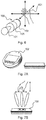
- FIG. 7A shows an exchangeable radar sensor arrangement in the form of an operating module in a perspective view and in a side view.
- FIG. 11 shows the interchangeable radar sensor assembly of FIG Figure 7A , in which the sensor device for gesture recognition is also shown.
- MIMO radar chips can be optimized by appropriate signal processing units to recognize gestures that are carried out by hand.
- these radar chips are installed in the operating module, for example, in such a way that the main emission direction of the gesture-recognizing radar chip is essentially aligned orthogonally to the display (cf. Figure 7B ).
- the operating module 102 is then installed in a field device (for example in a radar sensor 100) and is then located, for example, on the side of the field device housing opposite the process connection, as shown in FIG Fig. 6 is shown.
- the advantage of the radar method is that, in addition to distances, speeds can also be evaluated, which is not necessarily the case with other environmental monitoring sensors. Gesture recognition with increased information density using radar is only possible with the help of the speed component.
- the chirp sequence, FMCW or pulse Doppler method can be used for the environment monitoring radar module (second radar sensor arrangement 102).
- the FMCW or pulse radar method can be used for the measuring radar module (first radar sensor arrangement 101).
- the above radar methods can be used.
- the two radar sensor arrangements can be designed as MIMO systems. This means that several transmitting and / or receiving antennas can be present. This allows the main direction of emission and reception of the radar sensor arrangement to be controlled, which contributes significantly to the recognition of gestures (cf. Fig. 3 ).
- the gesture-recognizing radar sensor (more precisely: the second radar sensor arrangement 102) does not have to scan the surroundings all the time, it can be activated, for example, by the user knocking on the housing wall of the field device. After the call waiting, the operating module or the field device can then be controlled and parameterized using gestures. This process has the advantage that the field device is not screwed on must be, which can be advantageous for field devices that are used in potentially explosive areas.
- the operating module needs signaling devices to give the user feedback as to whether the commands entered via gesture control have been correctly understood.
- This feedback can be implemented optically (display, LED), acoustically (signal-accentuated) or vibronically (vibration of the housing).
- the additional radar module (second radar sensor arrangement) 102 is arranged so that the main radiation direction of the additional radar module is at an angle greater than 90 ° relative to the main radiation direction of the process measurement module.
- the two radar sensor arrangements 101, 102 can have different frequency ranges, radar modulation forms, signal processing algorithms, antenna constructions, antenna opening angles, number of transmitting and receiving antennas, measuring ranges, measuring time intervals, etc ...
- the measured variable can be determined using both radar sensor arrangements 101, 102.
- the second radar sensor arrangement 102 can be used to monitor the surroundings.
- the second radar sensor arrangement 102 can be used for gesture control.
- the radar sensor 100 can offer advantages in radar sensors for areas at risk of explosion, since the sensor does not have to be opened or the cover does not have to be screwed on to operate the sensor.
- the second radar sensor arrangement 102 for gesture control can have a plurality of transmitting and / or receiving antennas that allow analog or digital beam formation.
- Both radar sensor arrangements 101, 102 can be set up to be able to detect speeds as well as distances.
- the energy of the radar sensor arrangements 101, 102 can be drawn from an IO-Link, 4... 20 mA interface or a battery / accumulator.
- the user needs feedback as to whether the information entered was understood by the sensor.
- This can be in the form of a display, LEDs or a vibronic or acoustic signal, for example.
- the gesture control does not have to constantly scan the surroundings, it can be activated, for example, by "knocking on”.
- first radar sensor arrangement 101 and the second radar sensor arrangement 102 are integrated in a semiconductor module.
- Waveguides, coaxial conductors or dielectric waveguides can be used to route the signals to the respective antennas.
- the radar chip in the operating module can be designed as a MIMO, SIMO or MOSI chip (one or more transmitting or receiving antennas) and can thus operate beam shaping.
- the radar chip in the operating module can be set up according to the FMCW radar, the chirp sequence or the pulse Doppler method.
- the main beam direction of the second radar sensor arrangement 102 is orthogonal on the display of the operating module.
Priority Applications (3)
| Application Number | Priority Date | Filing Date | Title |
|---|---|---|---|
| EP19188373.5A EP3770632A1 (fr) | 2019-07-25 | 2019-07-25 | Dispositif des capteurs radar combiné ayant un capteur radar pour la mesure du niveau de remplissage et un captueur radar pour la surveillance de l'environnement |
| CN202010715483.9A CN112284489A (zh) | 2019-07-25 | 2020-07-23 | 雷达传感器、可更换的雷达传感器装置、现场设备和容器 |
| US16/938,588 US20210026001A1 (en) | 2019-07-25 | 2020-07-24 | Radar sensor, interchangeable radar sensor arrangement, field device and container |
Applications Claiming Priority (1)
| Application Number | Priority Date | Filing Date | Title |
|---|---|---|---|
| EP19188373.5A EP3770632A1 (fr) | 2019-07-25 | 2019-07-25 | Dispositif des capteurs radar combiné ayant un capteur radar pour la mesure du niveau de remplissage et un captueur radar pour la surveillance de l'environnement |
Publications (1)
| Publication Number | Publication Date |
|---|---|
| EP3770632A1 true EP3770632A1 (fr) | 2021-01-27 |
Family
ID=67438911
Family Applications (1)
| Application Number | Title | Priority Date | Filing Date |
|---|---|---|---|
| EP19188373.5A Pending EP3770632A1 (fr) | 2019-07-25 | 2019-07-25 | Dispositif des capteurs radar combiné ayant un capteur radar pour la mesure du niveau de remplissage et un captueur radar pour la surveillance de l'environnement |
Country Status (3)
| Country | Link |
|---|---|
| US (1) | US20210026001A1 (fr) |
| EP (1) | EP3770632A1 (fr) |
| CN (1) | CN112284489A (fr) |
Families Citing this family (3)
| Publication number | Priority date | Publication date | Assignee | Title |
|---|---|---|---|---|
| EP4116690A1 (fr) * | 2021-07-09 | 2023-01-11 | VEGA Grieshaber KG | Procédé de mesure et dispositif de mesure |
| US11885653B2 (en) * | 2021-09-24 | 2024-01-30 | Hydro Radar, LLC | Flow and level monitoring fluid system including nadir-facing and angle flow sensors with MIMO phase radar sensors |
| GB2622655A (en) * | 2022-09-22 | 2024-03-27 | Hydro Radar Llc | Flow and level monitor for fluid systems |
Citations (12)
| Publication number | Priority date | Publication date | Assignee | Title |
|---|---|---|---|---|
| EP2824433A1 (fr) * | 2013-07-08 | 2015-01-14 | VEGA Grieshaber KG | Dispositif de détermination de données de mesure universel dans des eaux |
| EP2824431A1 (fr) * | 2013-07-08 | 2015-01-14 | VEGA Grieshaber KG | Détermination du niveau et du taux de fluage d'un milieu |
| US20150253175A1 (en) * | 2014-03-05 | 2015-09-10 | Rosemount Tank Radar Ab | Low power radar level gauge system with integrated microwave circuit |
| WO2016176600A1 (fr) * | 2015-04-30 | 2016-11-03 | Google Inc. | Suivi de micro-mouvements sur la base de rf pour suivi et reconnaissance de gestes |
| US20160358054A1 (en) * | 2014-05-23 | 2016-12-08 | Cartasite, Inc. | Cargo monitoring |
| US20170097413A1 (en) * | 2015-10-06 | 2017-04-06 | Google Inc. | Radar-Enabled Sensor Fusion |
| DE102015219612A1 (de) * | 2015-10-09 | 2017-04-13 | Vega Grieshaber Kg | Systemarchitektur für einen MIMO Füllstandradar |
| EP3171138A1 (fr) * | 2015-11-17 | 2017-05-24 | VEGA Grieshaber KG | Dispositif d'antenne et procédé d'envoi et/ou de réception d'un signal |
| US20170284854A1 (en) * | 2014-03-20 | 2017-10-05 | Vega Grieshaber Kg | Portable device for orienting a fill-level measuring device on a container |
| US20180373340A1 (en) * | 2016-03-16 | 2018-12-27 | Boe Technology Group Co., Ltd. | Display control circuit, display control method and display device |
| EP3467447A1 (fr) * | 2017-10-06 | 2019-04-10 | VEGA Grieshaber KG | Appareil de mesure de niveau de remplissage à une pluralité des chips radar |
| DE102017217805A1 (de) * | 2017-10-06 | 2019-04-11 | Vega Grieshaber Kg | Radarfüllstandmessgerät mit Synchronisationssignal auf verschiedenen Leitungstypen |
Family Cites Families (12)
| Publication number | Priority date | Publication date | Assignee | Title |
|---|---|---|---|---|
| US7596242B2 (en) * | 1995-06-07 | 2009-09-29 | Automotive Technologies International, Inc. | Image processing for vehicular applications |
| DE19937723C2 (de) * | 1999-08-10 | 2001-10-04 | Bosch Gmbh Robert | Verfahren und Vorrichtung zur Bestimmung eines Höhenwinkelfehlers eines mehrstrahligen Radar-Sensors |
| DE19946161A1 (de) * | 1999-09-27 | 2001-04-26 | Siemens Ag | Verfahren zur Abstandsmessung |
| DE102013209075A1 (de) * | 2013-05-16 | 2014-11-20 | Robert Bosch Gmbh | Abfallbehältnis mit Sensoranordnung und Verfahren zum Überwachen eines Abfallbehältnisses |
| JP6479418B2 (ja) * | 2014-10-31 | 2019-03-06 | 古野電気株式会社 | 遠隔操舵システム、遠隔操作装置、及び遠隔操舵方法 |
| DE102015219276A1 (de) * | 2015-10-06 | 2017-04-06 | Vega Grieshaber Kg | 3D-Messung mit Master-Slave-Konzept |
| DE102016204274A1 (de) * | 2016-03-15 | 2017-09-21 | Volkswagen Aktiengesellschaft | System und Verfahren zum Erfassen einer Eingabegeste eines Nutzers |
| WO2018052894A1 (fr) * | 2016-09-14 | 2018-03-22 | Sears Brands, Llc | Dispositif de réfrigération à distributeur commandé par gestes |
| WO2019194867A2 (fr) * | 2017-11-06 | 2019-10-10 | Echodyne Corp | Commande dynamique basée sur un capteur intelligent et sur la rétroaction intelligente d'un paramètre d'un champ de vision vers lequel le capteur est dirigé |
| KR20190054664A (ko) * | 2017-11-14 | 2019-05-22 | 주식회사 포윈 | 360˚ 전방위 20미터 내 탐지용 fmcw 레이다 기술을 활용한 멀티센서 |
| DE102017127024A1 (de) * | 2017-11-16 | 2019-05-16 | Endress+Hauser Conducta Gmbh+Co. Kg | Verfahren zur Betreuung zumindest eines Feldgeräts der Prozessautomatisierungstechnik |
| US10732262B2 (en) * | 2017-12-18 | 2020-08-04 | Veoneer Us, Inc. | Apparatus and method for detecting alignment of sensor in an automotive detection system |
-
2019
- 2019-07-25 EP EP19188373.5A patent/EP3770632A1/fr active Pending
-
2020
- 2020-07-23 CN CN202010715483.9A patent/CN112284489A/zh active Pending
- 2020-07-24 US US16/938,588 patent/US20210026001A1/en active Pending
Patent Citations (12)
| Publication number | Priority date | Publication date | Assignee | Title |
|---|---|---|---|---|
| EP2824433A1 (fr) * | 2013-07-08 | 2015-01-14 | VEGA Grieshaber KG | Dispositif de détermination de données de mesure universel dans des eaux |
| EP2824431A1 (fr) * | 2013-07-08 | 2015-01-14 | VEGA Grieshaber KG | Détermination du niveau et du taux de fluage d'un milieu |
| US20150253175A1 (en) * | 2014-03-05 | 2015-09-10 | Rosemount Tank Radar Ab | Low power radar level gauge system with integrated microwave circuit |
| US20170284854A1 (en) * | 2014-03-20 | 2017-10-05 | Vega Grieshaber Kg | Portable device for orienting a fill-level measuring device on a container |
| US20160358054A1 (en) * | 2014-05-23 | 2016-12-08 | Cartasite, Inc. | Cargo monitoring |
| WO2016176600A1 (fr) * | 2015-04-30 | 2016-11-03 | Google Inc. | Suivi de micro-mouvements sur la base de rf pour suivi et reconnaissance de gestes |
| US20170097413A1 (en) * | 2015-10-06 | 2017-04-06 | Google Inc. | Radar-Enabled Sensor Fusion |
| DE102015219612A1 (de) * | 2015-10-09 | 2017-04-13 | Vega Grieshaber Kg | Systemarchitektur für einen MIMO Füllstandradar |
| EP3171138A1 (fr) * | 2015-11-17 | 2017-05-24 | VEGA Grieshaber KG | Dispositif d'antenne et procédé d'envoi et/ou de réception d'un signal |
| US20180373340A1 (en) * | 2016-03-16 | 2018-12-27 | Boe Technology Group Co., Ltd. | Display control circuit, display control method and display device |
| EP3467447A1 (fr) * | 2017-10-06 | 2019-04-10 | VEGA Grieshaber KG | Appareil de mesure de niveau de remplissage à une pluralité des chips radar |
| DE102017217805A1 (de) * | 2017-10-06 | 2019-04-11 | Vega Grieshaber Kg | Radarfüllstandmessgerät mit Synchronisationssignal auf verschiedenen Leitungstypen |
Also Published As
| Publication number | Publication date |
|---|---|
| US20210026001A1 (en) | 2021-01-28 |
| CN112284489A (zh) | 2021-01-29 |
Similar Documents
| Publication | Publication Date | Title |
|---|---|---|
| EP3770632A1 (fr) | Dispositif des capteurs radar combiné ayant un capteur radar pour la mesure du niveau de remplissage et un captueur radar pour la surveillance de l'environnement | |
| EP3746752B1 (fr) | Dispositif de mesure du niveau de remplissage | |
| EP1529198B1 (fr) | Systeme pour realiser un dispositif de structure modulaire qui sert a determiner une grandeur de processus physique, et composants normalises | |
| DE10047667A1 (de) | Leistungsarmes Radar-Füllstandmeßgerät mit verbesserter Diagnose | |
| EP2516973A2 (fr) | Procédé de détermination et de surveillance du niveau de remplissage d'un contenant, renfermant un fluide, selon un procédé de mesure du temps de propagation | |
| DE102007042043A1 (de) | Vorrichtung zur Ermittlung und Überwachung des Füllstands eines Füllguts in einem Behälter | |
| EP3724614A1 (fr) | Procédé pour simplifier la mise en service d'un appareil de terrain | |
| EP2527805A1 (fr) | Dispositif d'évaluation et procédé de détermination d'une grandeur caractéristique pour la position d'une surface limite dans un récipient | |
| DE102016108594B3 (de) | Verfahren zur Ermittlung des Füllstandes sowie zur Ermittlung zumindest einer Zusatzinformation | |
| CN113865668A (zh) | 具有多个雷达模块的Sil3级别雷达物位计测量系统 | |
| EP4158289A1 (fr) | Dispositif de mesure optique de niveau de remplissage | |
| EP4214477A1 (fr) | Étalonnage de jauges modulaires de niveau de remplissage | |
| DE102015120362A1 (de) | Verfahren zur Radar-basierten Messung des Füllstands | |
| WO2021013356A1 (fr) | Capteurs radars combinés comprenant un capteur radar pour mesurer un niveau de remplissage et un capteur radar pour surveiller un environnement | |
| DE102017124996A1 (de) | Radarbasiertes Füllstandsmessgerät | |
| US20220034700A1 (en) | Detection of event-based states during a fill level measurement | |
| US20240027252A1 (en) | Filling volume measurement | |
| EP4136413A1 (fr) | Affichage autonome pour appareils de mesure de niveau de remplissage et de niveau limite | |
| WO2020201223A1 (fr) | Appareil de mesure par radar avec surveillance intégrée de périmètre | |
| EP3719533B1 (fr) | Barrière à micro-ondes réfléchissante multidimensionnelle | |
| EP3696817B1 (fr) | Capteur radar doté d'une interface de communication | |
| WO2021254623A1 (fr) | Radar de niveau de remplissage pour capture de niveau et de topologie | |
| WO2023099269A1 (fr) | Dispositif de mesure de niveau de remplissage | |
| Bilewski et al. | Application of ultrasonic distance sensors for measuring height as a tool in unmanned aerial vehicles with a stabilized position in the vertical plane | |
| DE102021110017A1 (de) | Feldgerät mit ortsangepasster Parameterermittlung und/oder Messwertermittlung |
Legal Events
| Date | Code | Title | Description |
|---|---|---|---|
| PUAI | Public reference made under article 153(3) epc to a published international application that has entered the european phase |
Free format text: ORIGINAL CODE: 0009012 |
|
| STAA | Information on the status of an ep patent application or granted ep patent |
Free format text: STATUS: THE APPLICATION HAS BEEN PUBLISHED |
|
| AK | Designated contracting states |
Kind code of ref document: A1 Designated state(s): AL AT BE BG CH CY CZ DE DK EE ES FI FR GB GR HR HU IE IS IT LI LT LU LV MC MK MT NL NO PL PT RO RS SE SI SK SM TR |
|
| AX | Request for extension of the european patent |
Extension state: BA ME |
|
| STAA | Information on the status of an ep patent application or granted ep patent |
Free format text: STATUS: REQUEST FOR EXAMINATION WAS MADE |
|
| 17P | Request for examination filed |
Effective date: 20210702 |
|
| RBV | Designated contracting states (corrected) |
Designated state(s): AL AT BE BG CH CY CZ DE DK EE ES FI FR GB GR HR HU IE IS IT LI LT LU LV MC MK MT NL NO PL PT RO RS SE SI SK SM TR |
|
| STAA | Information on the status of an ep patent application or granted ep patent |
Free format text: STATUS: EXAMINATION IS IN PROGRESS |
|
| 17Q | First examination report despatched |
Effective date: 20230606 |