EP3770628A1 - Verfahren zur radarinterferenzabschwächung - Google Patents
Verfahren zur radarinterferenzabschwächung Download PDFInfo
- Publication number
- EP3770628A1 EP3770628A1 EP19188013.7A EP19188013A EP3770628A1 EP 3770628 A1 EP3770628 A1 EP 3770628A1 EP 19188013 A EP19188013 A EP 19188013A EP 3770628 A1 EP3770628 A1 EP 3770628A1
- Authority
- EP
- European Patent Office
- Prior art keywords
- time domain
- interference
- domain sample
- sequence
- sample
- Prior art date
- Legal status (The legal status is an assumption and is not a legal conclusion. Google has not performed a legal analysis and makes no representation as to the accuracy of the status listed.)
- Withdrawn
Links
- 238000000034 method Methods 0.000 title claims abstract description 66
- 230000000116 mitigating effect Effects 0.000 title description 2
- 238000001914 filtration Methods 0.000 claims description 41
- 238000012545 processing Methods 0.000 claims description 21
- 239000011159 matrix material Substances 0.000 claims description 11
- 238000011478 gradient descent method Methods 0.000 claims description 5
- 230000004044 response Effects 0.000 claims description 4
- 238000001514 detection method Methods 0.000 description 14
- 230000001629 suppression Effects 0.000 description 12
- 230000000875 corresponding effect Effects 0.000 description 10
- 230000008569 process Effects 0.000 description 8
- 230000003044 adaptive effect Effects 0.000 description 6
- 230000008901 benefit Effects 0.000 description 4
- 238000004891 communication Methods 0.000 description 3
- 238000004590 computer program Methods 0.000 description 3
- 230000000694 effects Effects 0.000 description 3
- 238000006243 chemical reaction Methods 0.000 description 2
- 238000009826 distribution Methods 0.000 description 2
- 230000008439 repair process Effects 0.000 description 2
- 238000003491 array Methods 0.000 description 1
- 230000008859 change Effects 0.000 description 1
- 230000002596 correlated effect Effects 0.000 description 1
- 230000001934 delay Effects 0.000 description 1
- 238000013461 design Methods 0.000 description 1
- 230000001627 detrimental effect Effects 0.000 description 1
- 238000005562 fading Methods 0.000 description 1
- 230000006870 function Effects 0.000 description 1
- 238000005259 measurement Methods 0.000 description 1
- 230000007246 mechanism Effects 0.000 description 1
- 230000003287 optical effect Effects 0.000 description 1
- 230000000737 periodic effect Effects 0.000 description 1
- 230000002085 persistent effect Effects 0.000 description 1
- 239000007787 solid Substances 0.000 description 1
- 230000007704 transition Effects 0.000 description 1
Images


Classifications
-
- G—PHYSICS
- G01—MEASURING; TESTING
- G01S—RADIO DIRECTION-FINDING; RADIO NAVIGATION; DETERMINING DISTANCE OR VELOCITY BY USE OF RADIO WAVES; LOCATING OR PRESENCE-DETECTING BY USE OF THE REFLECTION OR RERADIATION OF RADIO WAVES; ANALOGOUS ARRANGEMENTS USING OTHER WAVES
- G01S7/00—Details of systems according to groups G01S13/00, G01S15/00, G01S17/00
- G01S7/02—Details of systems according to groups G01S13/00, G01S15/00, G01S17/00 of systems according to group G01S13/00
- G01S7/023—Interference mitigation, e.g. reducing or avoiding non-intentional interference with other HF-transmitters, base station transmitters for mobile communication or other radar systems, e.g. using electro-magnetic interference [EMI] reduction techniques
-
- G—PHYSICS
- G01—MEASURING; TESTING
- G01S—RADIO DIRECTION-FINDING; RADIO NAVIGATION; DETERMINING DISTANCE OR VELOCITY BY USE OF RADIO WAVES; LOCATING OR PRESENCE-DETECTING BY USE OF THE REFLECTION OR RERADIATION OF RADIO WAVES; ANALOGOUS ARRANGEMENTS USING OTHER WAVES
- G01S13/00—Systems using the reflection or reradiation of radio waves, e.g. radar systems; Analogous systems using reflection or reradiation of waves whose nature or wavelength is irrelevant or unspecified
- G01S13/02—Systems using reflection of radio waves, e.g. primary radar systems; Analogous systems
- G01S13/06—Systems determining position data of a target
- G01S13/08—Systems for measuring distance only
- G01S13/32—Systems for measuring distance only using transmission of continuous waves, whether amplitude-, frequency-, or phase-modulated, or unmodulated
- G01S13/34—Systems for measuring distance only using transmission of continuous waves, whether amplitude-, frequency-, or phase-modulated, or unmodulated using transmission of continuous, frequency-modulated waves while heterodyning the received signal, or a signal derived therefrom, with a locally-generated signal related to the contemporaneously transmitted signal
- G01S13/343—Systems for measuring distance only using transmission of continuous waves, whether amplitude-, frequency-, or phase-modulated, or unmodulated using transmission of continuous, frequency-modulated waves while heterodyning the received signal, or a signal derived therefrom, with a locally-generated signal related to the contemporaneously transmitted signal using sawtooth modulation
-
- G—PHYSICS
- G01—MEASURING; TESTING
- G01S—RADIO DIRECTION-FINDING; RADIO NAVIGATION; DETERMINING DISTANCE OR VELOCITY BY USE OF RADIO WAVES; LOCATING OR PRESENCE-DETECTING BY USE OF THE REFLECTION OR RERADIATION OF RADIO WAVES; ANALOGOUS ARRANGEMENTS USING OTHER WAVES
- G01S13/00—Systems using the reflection or reradiation of radio waves, e.g. radar systems; Analogous systems using reflection or reradiation of waves whose nature or wavelength is irrelevant or unspecified
- G01S13/88—Radar or analogous systems specially adapted for specific applications
- G01S13/93—Radar or analogous systems specially adapted for specific applications for anti-collision purposes
- G01S13/931—Radar or analogous systems specially adapted for specific applications for anti-collision purposes of land vehicles
- G01S2013/9327—Sensor installation details
- G01S2013/93271—Sensor installation details in the front of the vehicles
Definitions
- the present disclosure relates to interference in radar signals, and in particular to suppression of such interference.
- the radar systems discussed herein are suitable as vehicle radar systems.
- radar transceivers that are arranged for generating radar signals that are transmitted, reflected and received by means of appropriate antennas comprised in the radar system.
- the radar signals may for example be in the form of FMCW (Frequency Modulated Continuous Wave) signals where frequency chirp signals are formed in a well-known manner.
- FMCW Frequency Modulated Continuous Wave
- radars may interfere with each other as frequency chirps cross or come close to each other in frequency. When this happens, a burst of interference somewhere within the received signal during one or more of the chirp signals can be observed.
- FFT Fast Fourier Transform
- the noise floor will be raised since the noise may be spread across a wide band of frequencies. This raising of the noise floor has the effect of reducing the range and accuracy of the radar, which of course is undesirable.
- EP3489710 A1 discloses an arrangement for radar interference suppression.
- interference mitigation is achieved by replacing obtained radar samples by modified samples which are generated based on frequency domain processing of batches of samples.
- additional interference suppression methods are desired.
- This object is achieved by a method for suppressing interference in a received radar signal.
- the method comprises obtaining a sequence of time domain samples of the received radar signal.
- the method also comprises determining, for a current time domain sample in the sequence of time domain samples, a corresponding predicted time domain sample of the radar signal, based on a weighted combination of at least part of the obtained sequence of time domain samples. Then, if interference is detected in the current time domain sample, the method replaces the current time domain sample by the corresponding predicted time domain sample in the sequence of time domain samples.
- This interference suppression method robustly suppresses interference in received radar signals and at the same time allows for efficient implementation in digital logic, which is an advantage.
- the method is not associated with high computational complexity, and offers processing with low delay, meaning that large amounts of radar data from, e.g., multiple antennas, can be handled without overloading a reasonably sized processing system.
- determining the predicted time domain sample is based on filtering the sequence of time domain samples by a Finite Impulse Response (FIR) filter defined by a vector of filter weights.
- FIR Finite Impulse Response
- the FIR filter allows for a particularly efficient digital implementation with low complexity and low processing delay.
- the FIR filter can be either a fixed filter with pre-configured filtering function or an adaptive filter which adapts to current filtering conditions.
- a gradient descent based method can be used to update filter weights. This method provides a computationally expensive yet accurate way to determine suitable filter weights.
- the filter design can be based on some autoregressive model, and the filter weights can be updated based on, e.g., the Burg method.
- determining the predicted time domain sample is based on filtering the sequence of time domain samples by a Kalman filter associated with a Kalman gain factor K and an estimated covariance matrix P.
- the Kalman filter is adaptive in that it adapts to current filtering conditions, without need for manually set thresholds and the like, which is an advantage.
- determining the predicted time domain sample is based on filtering the sequence of time domain samples in a forward direction F starting from a first time domain sample and in a reverse or opposite direction R ending at the first time domain sample, wherein the corresponding predicted time domain sample of the radar signal is obtained as a weighted combination of the filtering in forward and reverse directions.
- the method comprises detecting at least one onset time instant of interference based on the forward filtering, and a respective cessation time instant of interference based on the reverse filtering.
- the replacing comprises replacing a pre-determined length sub-sequence of time domain samples adjacent to the current time domain sample by a corresponding sequence of predicted time domain samples. Since an interference burst typically comprises a block of around 100 samples or more, it may be that not all samples within the burst meet the criteria for interference detection. This can be solved, e.g., with the use of a counter that is reset when an interference sample is detected and is incremented each subsequent sample point such that subsequent sample points are also considered interference until the counter reaches a threshold of perhaps 10 sample points or so. This ensures that the whole block of interference is replaced resulting in a signal without unwanted jumps or discontinuities, which is an advantage.
- interference is detected based on a difference between the current time domain sample and a previous time domain sample.
- interference is detected based on a difference between the predicted time domain sample and the current time domain sample. This is, under some circumstances, a more reliable method for detecting interference compared to, e.g., observing differences between consecutive samples in the obtained radar signal. A large error signifies a model mismatch in the filtering process, which is often due to the presence of interference. Thus, a more reliable method for detecting interference in a sequence of radar samples is provided.
- detection criteria for detecting interference is dynamically adapted depending on scenario. This way the method can be made more or less sensitive to interference. It may be a drawback to replace too many samples by predicted samples, in which case the detection criteria can be relaxed in order to maintain more samples when needed. This way the interference suppression can be adjusted based on the interference scenario, to work well in scenarios with relatively weak but commonly occurring interference as well as in scenarios with rare strong bursts of interference.
- the method also comprises determining an error based on a difference between the predicted time domain sample and the current time domain sample.
- Filtering the sequence of time domain samples may comprise updating filter weights based on the determined error.
- the filter can be adapted such as to minimize the error, thereby learning a model of what the received radar signal should look like in case no interference is present.
- the error can also be used to drive a Kalman filtering algorithm as mentioned above, or a gradient descent method for updating filter weights of an adaptive FIR filter or the like.
- the updating is only performed in case no interference is detected in the current time domain sample. This way a more robust filtering process is obtained.
- a set of filter weights representing the filter weights at different time delays are stored in memory. This way, when interference is detected, the filter weights can be reset to a state a few sample instants before the interference was detected, effectively providing a guard interval for filter update.
- control units and vehicles associated with the above-mentioned advantages.
- the herein disclosed methods may be executed in a vehicle or at least in part by a remote server wirelessly connected to the vehicle.
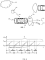
- Figure 1 shows a vehicle 100 equipped with a vehicle radar system 110, 130.
- the vehicle moves in a direction with velocity vector v ego .
- the vehicle radar system comprises at least one vehicle radar transceiver 110 and a radar data processing system or control unit 130.
- Some vehicles may comprise a plurality of radar transceivers configured in connection to an antenna array.
- the vehicle radar system 110, 130 comprises a transceiver arrangement that is arranged for generating and transmitting radar signals in the form of frequency modulated continuous wave (FMCW) chirp signals, and to receive reflected radar signals 125, where the transmitted signals have been reflected by an object 140.
- FMCW frequency modulated continuous wave
- a transmitted FMCW signal is in the form of a continuous wave where the output frequency F out varies from a first frequency f start to a second frequency f stop over the course of a ramp r, where each signal comprises repeating cycles of a plurality of frequency ramps r.
- a radar signal such as the radar signal exemplified in Figure 2 may be called a chirp signal.
- a cycle for such a chirp signal lasts for a certain cycle time t c , each ramp r lasts a certain ramp time t r , having a ramp period time t T . Between two consecutive ramps of the chirp signal there is a delay time t D .
- FMCW radar operation and signal processing is known in general and will not be discussed in more detail herein.
- the radar data processing system 130 is arranged to control operation of the radar transceiver 110, and to obtain data from the radar transceiver 110, such as detections or data points corresponding to objects 140 in vicinity of the vehicle 100.
- the radar transceiver 110 may comprise a single radar unit or a plurality of radar units, potentially of different type and/or of different configuration.
- the different radar units may, e.g., be arranged as front radars, side radars, and/or rearward facing radars.
- the vehicle radar system 110, 130 is arranged to generate a number of data points comprising coordinates in a relative coordinate system, i.e., relative to the location and orientation of the vehicle 100.
- the coordinates may be Cartesian coordinates, or they may be polar coordinates.
- the radar transceivers 110 may also be arranged to generate raw data for further processing, or a more refined feature vector extracted from the radar data.
- the data points may also comprise additional information, such as signal strength values or measures of signal-to-noise ratio (SNR).
- SNR signal-to-noise ratio
- One or more timestamps may also be associated with the information passing between the vehicle radar transceiver 110 and the control unit 130.
- the time stamps may be assigned per data point or be common to a set of data points.
- the radar transceiver 110 is associated with a field of view 120.
- a boresight direction 121 of the radar 110 often coincides with a center line of the field of view 120.
- the boresight direction may point in some other angle compared to the forward direction of the vehicle 100.
- the vehicle radar system 110, 130 in Figure 1 is subject to interference 180 from an external radar transceiver.
- Such interference can come from a plurality of different sources, including other radar transceivers on the same vehicle 100.
- interference occurs when two or more radar signals are close together in frequency for a period of time, specifically within the intermediate frequency (IF) receiving bandwidth of each other, or cross each other in frequency.
- IF intermediate frequency
- the net effect is that the time domain signal, i.e., the raw data or digitally sampled signal obtained after frequency down-conversion of the received radio frequency signal, experiences a burst of interference, which may be high compared to the wanted radar-return signal. There may be multiple interference bursts within a short time window.
- interference is here to be interpreted broadly to comprise any signal component or signal comprised in the radar signal which has a detrimental effect on performance of a system making use of the received radar signal. Consequently, interference may comprise any of, e.g., external interference from other transmitters and radio frequency sources, internal interference from circuitry of the radar transceiver or other active components located close to the radar receiver, and pulsed interference signals which are associated with limited time duration.
- some radar transceivers comprise antenna arrays which enable estimating not only distance to an object but also a bearing, i.e., an angle 122 measured from the radar boresight direction 121 to the detected object 140.
- This additional information may be of importance to vehicle control algorithms, but also means that more raw data is generated in the radar system.
- efficient radar signal processing is required in order to be able to handle the large amounts of data which are generated from the multiple reception antennas.
- Vehicle radar systems are often associated with strict requirements on delay. This means that any signal processing performed om the received radar signal will operate under delay constraints. Thus, complex algorithms either require significant processing power in order to meet delay constraints or must be excluded due to the delay constraints.
- the vehicle radar system 110,130 may be connected via wireless link 150 to a remote server 160, which in turn may be comprised in a remote network 170.
- This server and network may be configured to assist the vehicle 100 in performing radar interference suppression.
- the remote server 160 may be arranged to configure parameters such as detection thresholds used by the control unit 130 and the like remotely.
- An optional storage module may also be comprised in the vehicle radar system.
- the storage module may store data comprising information about a surrounding environment of the vehicle 100 and about past vehicle operations, such as past experiences of radar interference and radar interference suppression operations. The storage module will be discussed in more detail below in connection to Figure 7 .
- the radar interference suppression algorithms discussed herein mainly operate at baseband level, i.e., after down-conversion from the operational radio frequency.
- the techniques are based on the realization that interference generates bursts of distortion at baseband which can be detected.
- the baseband signal can be repaired by prediction samples, which predict what the radar signal would have looked in case no interference was present. This prediction is made possible at least in part since the baseband signal is relatively narrowband and also often periodic, which means that it is correlated in time.
- a current sample of the radar signal can be efficiently approximated, at least to some degree, by a weighted combination of adjacent samples in the received signal. This weighted combination can be efficiently obtained from a filtering process operating on the received radar signal.
- Figures 3A-3C show graphs of example baseband radar signal amplitude A over time in Volts, which illustrate the general idea behind the interference suppression methods disclosed herein.
- Figure 3A shows a received radar signal 310 at baseband. A part 320 of the received signal from time instant 321 to time instant 322 has been subjected to interference. This interference will complicate object detection by, e.g., raising noise floor. It is desired to suppress this interference.
- This prediction 330 is illustrated in Figure 3B with a dashed line.
- the prediction can be obtained, e.g., as a weighted combination 340 of the received radar signal outside 345, 346 of the interfered section 320.
- the distorted section 320 can be replaced by the prediction 330, as illustrated in Figure 3C . This way distortion can be suppressed in an efficient and reliable manner, which is an objective of the herein disclosed techniques.
- the generation of the prediction signal can be performed in a particularly efficient manner based on a weighted combination of time domain samples before the interfered section 345. This will be exemplified and discussed below in connection to Figure 4 .
- the sequence of time domain samples can also be filtered in both forward F and reverse R directions as indicated in Figure 3D , i.e., predicting based on both past and future samples of the received radar signal relative to the interfered section 320.
- the forward filter filtering in direction F is likely to be more accurate and generate a smaller prediction error compared to the reverse filter filtering in direction R.
- the reverse is more likely to be the case, i.e., that the reverse filter generates a smaller error compared to the forward filter. It is proposed herein to merge the two filter outputs by weighting each filter output according to how long into the interfered part the current sample is.
- the weighting can be linear as indicated in Figure 3D , where the forward filter weight w1 355 starts from 1.0, and then linearly declines to 0.0, while the reverse filter weight w2 365 starts from 0.0 and linearly increases up to 1.0.
- the two filter weights then always sum to one.
- the weighting can also be non-linear, e.g., based on a squared distance from the start of filtering.
- x1'[n] is the predicted sample from the forward filter
- x2'[n] is the predicted sample from the reverse filter.
- Figure 3E illustrates the prediction 330 (dashed line) obtained by merging the two filter outputs. It is noted that the forward filter 350 (dash-dotted line) dominates the prediction to the left, while the reverse filter 360 (dashed-double dotted line) dominates the prediction to the right.
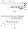
- Figure 4 shows an example of generating the prediction signal 445;
- a sequence of time domain samples ⁇ x[1], x[2], ..., x[16] ⁇ of the received radar signal 125 has been obtained, e.g., from an analog to digital converter (ADC).
- the sequence of time domain samples represents a baseband version of the received radar signal 125.
- a prediction sample x'[n] is generated by filtering the sequence up to the current sample x[n].
- the filter shown in Figure 4 is a Finite Impulse Response (FIR) filter defined by a vector of weights ⁇ a[1], a[2], ..., a[8] ⁇ .
- the filter weights may be fixed or may be adapted over time, as will be discussed below in more detail.
- the weights may be complex valued or real valued.
- interference 180 is detected in some current time domain sample (x[n], 415), it is possible to replace the current time domain sample (x[n], 415) by the corresponding predicted time domain sample (x' [n], 445) in the sequence of time domain samples ( ⁇ x[1], x[2], ..., x[T] ⁇ , 410) in order to suppress interference and 'repair' the ADC output signal.
- determining the predicted time domain sample x'[n], 445 is based on filtering S23 the sequence of time domain samples ⁇ x[1], x[2], ..., x[T] ⁇ , 410 in a forward direction F starting from a first time domain sample and in a reverse direction R ending at the first time domain sample, wherein the corresponding predicted time domain sample x'[n], 445 of the radar signal is obtained as a weighted combination of the filtering in forward F and reverse R directions.
- the coefficients in vector a may be set to zero at the start of the current chirp, or the values from the previous chirp may be used as a starting vector.
- the process operating in the reverse direction R would typically but not necessarily use the vector ⁇ a[1], a[2], ..., a[N] ⁇ already learned running in the forward direction F since the coefficients are related to the frequency of the signal components rather than the phase.
- the weighting between the two filtering processes can be determined based on a filtered length, i.e., a time of convergence of the two filters.
- a filtered length i.e., a time of convergence of the two filters.
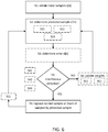
- Figure 6 shows a flow chart illustrating details of methods disclosed herein. There is shown a method for suppressing interference 180 in a received radar signal 125. The method comprises obtaining S1 a sequence of time domain samples ⁇ x[1], x[2], ..., x[T] ⁇ , 410 of the received radar signal 125.
- the obtained time domain samples of the received radar signal may, e.g., originate from an ADC arranged to convert an analog baseband radar signal into discrete time domain samples of the radar signal. This means that the methods are applicable to digital baseband signals. In particular to baseband FMCW radar signals.
- the method comprises determining S2, for a current time domain sample x[n], 415 in the sequence of time domain samples 410, a corresponding predicted time domain sample x'[n], 445 of the radar signal, based on a weighted combination 420, 430, 440 of at least part of the obtained sequence of time domain samples ⁇ x[1], x[2], ..., x[T] ⁇ , 410.
- weighted combination was discussed above in connection to Figure 4 , additional examples will be given below.
- determining the predicted time domain sample x'[n], 445 can be based on filtering S21 the sequence of time domain samples ⁇ x[1], x[2], ..., x[T] ⁇ , 410 by a Finite Impulse Response (FIR) filter defined by a vector of weights ⁇ a[1], a[2], ..., a[N] ⁇ , as discussed above in connection to Figure 4 .
- FIR Finite Impulse Response
- the weights in this filter can be fixed, obtained from an external source such as the server 160 or network 170, or adapted over time.
- the sequence of time domain samples ⁇ x[1], x[2], ..., x[T] ⁇ , 410 of the received radar signal 125 can be approximated or modelled by an autoregressive (AR) model.
- An autoregressive model specifies that the output variable, i.e., the time domain samples x[n], depends linearly on the previous values and on a stochastic term (an imperfectly predictable term).
- the model is in the form of a stochastic difference equation.
- MA moving-average
- it is a special case and key component of the more general autoregressive moving average (ARMA) and autoregressive integrated moving average (ARIMA) models of time series.
- ARMA autoregressive moving average
- ARIMA autoregressive integrated moving average
- the weights of the filter a number of different known methods can be used.
- One such example is the Burg method, also sometimes referred to as the 'maximum entropy estimate'.
- the value of K can be adapted to be larger in the beginning of a chirp signal and smaller towards the end of the chirp signal.
- the filter weight update expression above uses the same value of K for all filter weights, according to some aspects, different weights can be used for different tap coefficients. This will cause a different rate of convergence at different parts of the filter, which may be advantageous in case long filters are used, where the end sections of the filter will have relatively small weight values that require more careful (slow) update compared.
- the method comprises determining S3 an error e[n] based on a difference 450 between the predicted time domain sample x'[n], 445 and the current time domain sample x[n], 415, wherein filtering the sequence of time domain samples ⁇ x[1], x[2], ..., x[T] ⁇ , 410 comprises updating S6 filter weights based on the error e[n].
- LMS Least Mean Squares
- FZ Zero forcing
- Adaptive filtering is known in general and will therefore not be discussed in more detail herein.
- FIG. 5 illustrates an example of this type of set-up.
- the weights of the weighted combination 420 are stored for a number of time lags, in the example four samples of lag is used.
- the filter weights 520 represent what the filter weights looked like before update into the weighted combination 420.
- the filter weights 520' represent what the filter weights 520 was before update, and so on for the weights 520" and 520"'.
- interference is detected, one of these sets of filter weights can be used instead of the potentially corrupted weights in 420. Which one depends on the selected guard period. A gradually increasing interference warrants larger guard period while an abrupt onset of interference may require less guard period.
- determining the predicted time domain sample x'[n], 445 is based on filtering S22 the sequence of time domain samples ⁇ x[1], x[2], ..., x[T] ⁇ , 410 by a Kalman filter associated with a Kalman gain factor K and an estimated covariance matrix P.
- k in a Kalman filter algorithm at sample k (or, equivalently, at discrete time index k) given data input up to time k is determined as P k
- k ( I - K k H k ) P k
- k -1 F k P k -1
- Previous and future measured chirp signal can also be used to determine filter weights. For instance, using FIR filter weights calculated by, e.g., the Kalman method from a previously measured chirp, on the assumption that the targets will only change in amplitude and frequency slowly.
- the method comprises replacing S5 the current time domain sample x[n], 415 by the corresponding predicted time domain sample x'[n], 445 in the sequence of time domain samples ⁇ x[1], x[2], ..., x[T] ⁇ , 410. This way an interference suppressed radar signal is provided.
- the method comprises detecting S41 at least one onset time instant of interference based on the forward filtering, and a respective cessation time instant of interference based on the reverse filtering.
- the detection can be based on comparing the error e[n] to a threshold value. This way a section of interference can be bounded to lie between a start time instant and a stop time instant. Samples within this section can be replaced with predicted samples to suppress interference in the received radar signal 125.
- interference can be detected S41 based on a difference between the current time domain sample x[n], 415 and a previous time domain sample x[n-1].
- the difference can, e.g., be an absolute value, or a squared value, or the like.
- Detection can be based on comparing the difference to a pre-configured or adaptive threshold value.
- the detection can also be based on statistical arguments built on an assumed distribution of the differences.
- interference can be detected based on sequences of differences instead of based on single samples of difference. A likelihood of a given sequence of differences can be determined and compared against a threshold, which threshold can be pre-determined or adapted as the method proceeds.
- interference is detected S42 based on a difference 450 between the predicted time domain sample x'[n], 445 and the current time domain sample x[n], 415.
- interference is based on the error signal discussed above in connection to filter weight update.
- the magnitude of the error term would then be compared to a pre-determined or adaptive threshold to determine if a noise burst was present. While moving from left to right across the raw data, the error would have been observed to drop after the vector a had converged to or learnt the correct values for the current chirp. If the error suddenly rises, then that could indicate an interference burst.
- the threshold would be dynamic across the chirp for example based on a multiple of the standard deviation of the error signal after it had converged.
- the criteria for detecting interference can be fixed or dynamically adapted depending on scenario. For instance, some scenarios may comprise only very little interference. In such cases a more sensitive interference detection algorithm may be warranted. However, in some other cases interference may be abundant, in which case the sensitive algorithm may try to replace all the samples, which may not be preferred due to filter stability and other issues.
- an interference burst typically comprises a block of around 100 samples or more, it may be that not all samples within the burst meet the criteria for interference detection.
- This potential issue can be solved with the use of a counter that is reset when an interference sample is detected and is incremented each subsequent sample point such that subsequent sample points are also considered interference until the counter reaches a threshold of perhaps 10 sample points or so. This ensures that the whole block, or at least the main part, of interference is replaced resulted in a signal without unwanted jumps.
- the replacing comprises replacing S51 a pre-determined length sub-sequence of time domain samples adjacent to the current time domain sample x[n] by a corresponding sequence of predicted time domain samples. The length may be pre-configured, adapted, or obtained from the remote server 160.
- the method implements a mechanism which only permits filter update in case no interference, or at least no significant level of interference, is present.
- Thresholds associated with interference detection for replacement and interference detection for filter update may be the same or may be different thresholds.
- the updating is only performed S62 in case no interference is detected in the current time domain sample x[n], 415.
- the thresholds for interference detection related to filter update and related to replacement may be different. For instance, the threshold related to filter update may be lower than the threshold related to replacement by the predicted sample.
- One way to set thresholds is by way of the covariance matrix estimate from the Kalman filter discussed above.
- This covariance estimate describes likelihoods of observing error signals at a given magnitude. Thus, if an error is large enough to indicate interference can be decided based on the current estimate of covariance obtained from the Kalman filter.
- FIG. 7 schematically illustrates, in terms of a number of functional units, the components of the control unit 130 according to an embodiment.
- Processing circuitry 710 is provided using any combination of one or more of a suitable central processing unit (CPU), multiprocessor, microcontroller, digital signal processor (DSP), dedicated hardware accelerator, etc., capable of executing software instructions stored in a computer program product, e.g. in the form of a storage medium 730.
- the processing circuitry 710 may further be provided as at least one application specific integrated circuit (ASIC), or field programmable gate array (FPGA).
- ASIC application specific integrated circuit
- FPGA field programmable gate array
- the processing circuitry 710 is configured to cause the control unit 130 to perform a set of operations, or steps. These operations, or steps, were discussed above in connection to Figure 5 .
- the storage medium 730 may store the set of operations
- the processing circuitry 710 may be configured to retrieve the set of operations from the storage medium 730 to cause the control node 130 to perform the set of operations.
- the set of operations may be provided as a set of executable instructions.
- the processing circuitry 710 is thereby arranged to execute methods as herein disclosed.
- the storage medium 730 may also comprise persistent storage, which, for example, can be any single one or combination of magnetic memory, optical memory, solid state memory or even remotely mounted memory.
- the control unit 130 may further comprise a communications interface 720 for communications with at least one radar device, i.e., a radar interface 720.
- the radar interface 720 may comprise one or more transmitters and receivers, comprising analogue and digital components and a suitable number of ports for wired or wireless communication.
- the processing circuitry 710 is adapted to control the general operation of the control node 130 e.g. by sending data and control signals to the radar interface 720 and the storage medium 730, by receiving data and reports from the radar interface 720, and by retrieving data and instructions from the storage medium 730.
- Other components, as well as the related functionality, of the control node 130 are omitted in order not to obscure the concepts presented herein.
- Figure 8 shows a computer program product 800 comprising computer executable instructions 810 to execute any of the methods disclosed herein.
Priority Applications (1)
| Application Number | Priority Date | Filing Date | Title |
|---|---|---|---|
| EP19188013.7A EP3770628A1 (de) | 2019-07-24 | 2019-07-24 | Verfahren zur radarinterferenzabschwächung |
Applications Claiming Priority (1)
| Application Number | Priority Date | Filing Date | Title |
|---|---|---|---|
| EP19188013.7A EP3770628A1 (de) | 2019-07-24 | 2019-07-24 | Verfahren zur radarinterferenzabschwächung |
Publications (1)
| Publication Number | Publication Date |
|---|---|
| EP3770628A1 true EP3770628A1 (de) | 2021-01-27 |
Family
ID=67438672
Family Applications (1)
| Application Number | Title | Priority Date | Filing Date |
|---|---|---|---|
| EP19188013.7A Withdrawn EP3770628A1 (de) | 2019-07-24 | 2019-07-24 | Verfahren zur radarinterferenzabschwächung |
Country Status (1)
| Country | Link |
|---|---|
| EP (1) | EP3770628A1 (de) |
Cited By (2)
| Publication number | Priority date | Publication date | Assignee | Title |
|---|---|---|---|---|
| CN113391287A (zh) * | 2021-06-10 | 2021-09-14 | 哈尔滨工业大学 | 基于时间序列的高频地波雷达海态数据融合方法 |
| EP4109124A1 (de) * | 2021-06-21 | 2022-12-28 | Aptiv Technologies Limited | Radarinterferenzunterdrückung mit signalmusteranpassung |
Citations (6)
| Publication number | Priority date | Publication date | Assignee | Title |
|---|---|---|---|---|
| EP0932838A1 (de) * | 1996-10-17 | 1999-08-04 | CelsiusTech Electronics AB | Verfahren zur störungsunterdrückung in einem fmcw-radar |
| EP1672379A2 (de) * | 2004-12-15 | 2006-06-21 | VALEO RAYTHEON SYSTEMS Inc. | System und Verfahren zur Verminderung eines Radarstörsignals |
| DE102014114110A1 (de) * | 2014-09-29 | 2016-03-31 | Hella Kgaa Hueck & Co. | Radarsensor |
| DE102014226073A1 (de) * | 2014-12-16 | 2016-06-16 | Robert Bosch Gmbh | Verfahren und Vorrichtung zum Betreiben eines Radarsystems eines Kraftfahrzeugs |
| WO2017187306A1 (en) * | 2016-04-25 | 2017-11-02 | Uhnder, Inc. | Adaptive filtering for fmcw interference mitigation in pmcw radar systems |
| EP3489710A1 (de) | 2017-11-23 | 2019-05-29 | Veoneer Sweden AB | Radarinterferenzunterdrückung |
-
2019
- 2019-07-24 EP EP19188013.7A patent/EP3770628A1/de not_active Withdrawn
Patent Citations (6)
| Publication number | Priority date | Publication date | Assignee | Title |
|---|---|---|---|---|
| EP0932838A1 (de) * | 1996-10-17 | 1999-08-04 | CelsiusTech Electronics AB | Verfahren zur störungsunterdrückung in einem fmcw-radar |
| EP1672379A2 (de) * | 2004-12-15 | 2006-06-21 | VALEO RAYTHEON SYSTEMS Inc. | System und Verfahren zur Verminderung eines Radarstörsignals |
| DE102014114110A1 (de) * | 2014-09-29 | 2016-03-31 | Hella Kgaa Hueck & Co. | Radarsensor |
| DE102014226073A1 (de) * | 2014-12-16 | 2016-06-16 | Robert Bosch Gmbh | Verfahren und Vorrichtung zum Betreiben eines Radarsystems eines Kraftfahrzeugs |
| WO2017187306A1 (en) * | 2016-04-25 | 2017-11-02 | Uhnder, Inc. | Adaptive filtering for fmcw interference mitigation in pmcw radar systems |
| EP3489710A1 (de) | 2017-11-23 | 2019-05-29 | Veoneer Sweden AB | Radarinterferenzunterdrückung |
Cited By (3)
| Publication number | Priority date | Publication date | Assignee | Title |
|---|---|---|---|---|
| CN113391287A (zh) * | 2021-06-10 | 2021-09-14 | 哈尔滨工业大学 | 基于时间序列的高频地波雷达海态数据融合方法 |
| CN113391287B (zh) * | 2021-06-10 | 2023-09-01 | 哈尔滨工业大学 | 基于时间序列的高频地波雷达海态数据融合方法 |
| EP4109124A1 (de) * | 2021-06-21 | 2022-12-28 | Aptiv Technologies Limited | Radarinterferenzunterdrückung mit signalmusteranpassung |
Similar Documents
| Publication | Publication Date | Title |
|---|---|---|
| Romero et al. | Waveform design in signal-dependent interference and application to target recognition with multiple transmissions | |
| US5900835A (en) | Coherent hidden markov model | |
| EP3779508B1 (de) | Umleitung der radar sendegleistung zum verringern der auswirkung eines störungssignals | |
| Mishra et al. | Performance of time delay estimation in a cognitive radar | |
| JP5371248B2 (ja) | レーダ装置 | |
| US8014230B2 (en) | Adaptive array control device, method and program, and adaptive array processing device, method and program using the same | |
| CN110646769B (zh) | 一种适用于lte外辐射源雷达的时域杂波抑制方法 | |
| Malanowski | Detection and parameter estimation of manoeuvring targets with passive bistatic radar | |
| EP3770628A1 (de) | Verfahren zur radarinterferenzabschwächung | |
| JP2012181052A (ja) | 相関抑圧フィルタ、ウェイト算出方法、ウェイト算出装置、アダプティブアレーアンテナ及びレーダ装置 | |
| JPH055778A (ja) | 不要信号抑圧装置 | |
| US8279113B2 (en) | Method for filtering a radar signal after it has been reflected by a target | |
| JP6355546B2 (ja) | 目標検出装置 | |
| Yu et al. | Novel robust beamformers for coherent interference suppression with direction-of-arrival estimation errors | |
| EP3828585B1 (de) | Fahrzeugsteuerung unter schweren radarstörungsbedingungen | |
| CN113376607B (zh) | 机载分布式雷达小样本空时自适应处理方法 | |
| JP2015125118A (ja) | 目標検出装置 | |
| US11852750B2 (en) | Method and apparatus for radar signal processing using recurrent neural network | |
| CN116953631A (zh) | 全极化雷达发射波形优化方法、计算机装置和存储介质 | |
| JP2013113722A (ja) | レーダ装置 | |
| CN110299926A (zh) | 一种面向低信噪比环境的水声信号检测方法 | |
| CN115238439A (zh) | 基于马尔可夫决策过程的探测系统博弈波形的设计方法 | |
| Butler et al. | Multistatic target classification with adaptive waveforms | |
| Wang | Direct signal recovery and masking effect removal exploiting sparsity for passive bistatic radar | |
| KR102311970B1 (ko) | 수신 신호의 도래각을 추적하는 장치 및 그 방법 |
Legal Events
| Date | Code | Title | Description |
|---|---|---|---|
| PUAI | Public reference made under article 153(3) epc to a published international application that has entered the european phase |
Free format text: ORIGINAL CODE: 0009012 |
|
| STAA | Information on the status of an ep patent application or granted ep patent |
Free format text: STATUS: THE APPLICATION HAS BEEN PUBLISHED |
|
| AK | Designated contracting states |
Kind code of ref document: A1 Designated state(s): AL AT BE BG CH CY CZ DE DK EE ES FI FR GB GR HR HU IE IS IT LI LT LU LV MC MK MT NL NO PL PT RO RS SE SI SK SM TR |
|
| AX | Request for extension of the european patent |
Extension state: BA ME |
|
| STAA | Information on the status of an ep patent application or granted ep patent |
Free format text: STATUS: REQUEST FOR EXAMINATION WAS MADE |
|
| 17P | Request for examination filed |
Effective date: 20210706 |
|
| RBV | Designated contracting states (corrected) |
Designated state(s): AL AT BE BG CH CY CZ DE DK EE ES FI FR GB GR HR HU IE IS IT LI LT LU LV MC MK MT NL NO PL PT RO RS SE SI SK SM TR |
|
| RAP1 | Party data changed (applicant data changed or rights of an application transferred) |
Owner name: ARRIVER SOFTWARE AB |
|
| STAA | Information on the status of an ep patent application or granted ep patent |
Free format text: STATUS: EXAMINATION IS IN PROGRESS |
|
| 17Q | First examination report despatched |
Effective date: 20230606 |
|
| STAA | Information on the status of an ep patent application or granted ep patent |
Free format text: STATUS: THE APPLICATION IS DEEMED TO BE WITHDRAWN |
|
| 18D | Application deemed to be withdrawn |
Effective date: 20231017 |