EP3769933A1 - System und verfahren zum herstellen eines behälters - Google Patents
System und verfahren zum herstellen eines behälters Download PDFInfo
- Publication number
- EP3769933A1 EP3769933A1 EP20176405.7A EP20176405A EP3769933A1 EP 3769933 A1 EP3769933 A1 EP 3769933A1 EP 20176405 A EP20176405 A EP 20176405A EP 3769933 A1 EP3769933 A1 EP 3769933A1
- Authority
- EP
- European Patent Office
- Prior art keywords
- container
- coating
- cooling
- path
- containers
- Prior art date
- Legal status (The legal status is an assumption and is not a legal conclusion. Google has not performed a legal analysis and makes no representation as to the accuracy of the status listed.)
- Granted
Links
Images


Classifications
-
- B—PERFORMING OPERATIONS; TRANSPORTING
- B29—WORKING OF PLASTICS; WORKING OF SUBSTANCES IN A PLASTIC STATE IN GENERAL
- B29C—SHAPING OR JOINING OF PLASTICS; SHAPING OF MATERIAL IN A PLASTIC STATE, NOT OTHERWISE PROVIDED FOR; AFTER-TREATMENT OF THE SHAPED PRODUCTS, e.g. REPAIRING
- B29C49/00—Blow-moulding, i.e. blowing a preform or parison to a desired shape within a mould; Apparatus therefor
- B29C49/42—Component parts, details or accessories; Auxiliary operations
- B29C49/4273—Auxiliary operations after the blow-moulding operation not otherwise provided for
-
- B—PERFORMING OPERATIONS; TRANSPORTING
- B29—WORKING OF PLASTICS; WORKING OF SUBSTANCES IN A PLASTIC STATE IN GENERAL
- B29C—SHAPING OR JOINING OF PLASTICS; SHAPING OF MATERIAL IN A PLASTIC STATE, NOT OTHERWISE PROVIDED FOR; AFTER-TREATMENT OF THE SHAPED PRODUCTS, e.g. REPAIRING
- B29C49/00—Blow-moulding, i.e. blowing a preform or parison to a desired shape within a mould; Apparatus therefor
- B29C49/42—Component parts, details or accessories; Auxiliary operations
- B29C49/64—Heating or cooling preforms, parisons or blown articles
- B29C49/66—Cooling by refrigerant introduced into the blown article
-
- B—PERFORMING OPERATIONS; TRANSPORTING
- B29—WORKING OF PLASTICS; WORKING OF SUBSTANCES IN A PLASTIC STATE IN GENERAL
- B29C—SHAPING OR JOINING OF PLASTICS; SHAPING OF MATERIAL IN A PLASTIC STATE, NOT OTHERWISE PROVIDED FOR; AFTER-TREATMENT OF THE SHAPED PRODUCTS, e.g. REPAIRING
- B29C49/00—Blow-moulding, i.e. blowing a preform or parison to a desired shape within a mould; Apparatus therefor
- B29C49/42—Component parts, details or accessories; Auxiliary operations
- B29C49/64—Heating or cooling preforms, parisons or blown articles
-
- B—PERFORMING OPERATIONS; TRANSPORTING
- B29—WORKING OF PLASTICS; WORKING OF SUBSTANCES IN A PLASTIC STATE IN GENERAL
- B29C—SHAPING OR JOINING OF PLASTICS; SHAPING OF MATERIAL IN A PLASTIC STATE, NOT OTHERWISE PROVIDED FOR; AFTER-TREATMENT OF THE SHAPED PRODUCTS, e.g. REPAIRING
- B29C49/00—Blow-moulding, i.e. blowing a preform or parison to a desired shape within a mould; Apparatus therefor
- B29C49/24—Lining or labelling
-
- B—PERFORMING OPERATIONS; TRANSPORTING
- B29—WORKING OF PLASTICS; WORKING OF SUBSTANCES IN A PLASTIC STATE IN GENERAL
- B29C—SHAPING OR JOINING OF PLASTICS; SHAPING OF MATERIAL IN A PLASTIC STATE, NOT OTHERWISE PROVIDED FOR; AFTER-TREATMENT OF THE SHAPED PRODUCTS, e.g. REPAIRING
- B29C49/00—Blow-moulding, i.e. blowing a preform or parison to a desired shape within a mould; Apparatus therefor
- B29C49/24—Lining or labelling
- B29C2049/2404—Lining or labelling inside the article
-
- B—PERFORMING OPERATIONS; TRANSPORTING
- B29—WORKING OF PLASTICS; WORKING OF SUBSTANCES IN A PLASTIC STATE IN GENERAL
- B29C—SHAPING OR JOINING OF PLASTICS; SHAPING OF MATERIAL IN A PLASTIC STATE, NOT OTHERWISE PROVIDED FOR; AFTER-TREATMENT OF THE SHAPED PRODUCTS, e.g. REPAIRING
- B29C49/00—Blow-moulding, i.e. blowing a preform or parison to a desired shape within a mould; Apparatus therefor
- B29C49/42—Component parts, details or accessories; Auxiliary operations
- B29C49/64—Heating or cooling preforms, parisons or blown articles
- B29C49/6604—Thermal conditioning of the blown article
- B29C2049/6606—Cooling the article
- B29C2049/6653—Cooling the article the medium being other than cooled air
-
- B—PERFORMING OPERATIONS; TRANSPORTING
- B29—WORKING OF PLASTICS; WORKING OF SUBSTANCES IN A PLASTIC STATE IN GENERAL
- B29C—SHAPING OR JOINING OF PLASTICS; SHAPING OF MATERIAL IN A PLASTIC STATE, NOT OTHERWISE PROVIDED FOR; AFTER-TREATMENT OF THE SHAPED PRODUCTS, e.g. REPAIRING
- B29C49/00—Blow-moulding, i.e. blowing a preform or parison to a desired shape within a mould; Apparatus therefor
- B29C49/42—Component parts, details or accessories; Auxiliary operations
- B29C49/64—Heating or cooling preforms, parisons or blown articles
- B29C49/6604—Thermal conditioning of the blown article
- B29C2049/6606—Cooling the article
- B29C2049/6676—Cooling the article the medium being oriented towards special areas of the blown article
- B29C2049/6692—Bottom area
-
- B—PERFORMING OPERATIONS; TRANSPORTING
- B29—WORKING OF PLASTICS; WORKING OF SUBSTANCES IN A PLASTIC STATE IN GENERAL
- B29C—SHAPING OR JOINING OF PLASTICS; SHAPING OF MATERIAL IN A PLASTIC STATE, NOT OTHERWISE PROVIDED FOR; AFTER-TREATMENT OF THE SHAPED PRODUCTS, e.g. REPAIRING
- B29C2949/00—Indexing scheme relating to blow-moulding
- B29C2949/07—Preforms or parisons characterised by their configuration
- B29C2949/0715—Preforms or parisons characterised by their configuration the preform having one end closed
-
- B—PERFORMING OPERATIONS; TRANSPORTING
- B29—WORKING OF PLASTICS; WORKING OF SUBSTANCES IN A PLASTIC STATE IN GENERAL
- B29C—SHAPING OR JOINING OF PLASTICS; SHAPING OF MATERIAL IN A PLASTIC STATE, NOT OTHERWISE PROVIDED FOR; AFTER-TREATMENT OF THE SHAPED PRODUCTS, e.g. REPAIRING
- B29C49/00—Blow-moulding, i.e. blowing a preform or parison to a desired shape within a mould; Apparatus therefor
- B29C49/02—Combined blow-moulding and manufacture of the preform or the parison
- B29C49/06—Injection blow-moulding
-
- B—PERFORMING OPERATIONS; TRANSPORTING
- B29—WORKING OF PLASTICS; WORKING OF SUBSTANCES IN A PLASTIC STATE IN GENERAL
- B29C—SHAPING OR JOINING OF PLASTICS; SHAPING OF MATERIAL IN A PLASTIC STATE, NOT OTHERWISE PROVIDED FOR; AFTER-TREATMENT OF THE SHAPED PRODUCTS, e.g. REPAIRING
- B29C49/00—Blow-moulding, i.e. blowing a preform or parison to a desired shape within a mould; Apparatus therefor
- B29C49/42—Component parts, details or accessories; Auxiliary operations
- B29C49/4273—Auxiliary operations after the blow-moulding operation not otherwise provided for
- B29C49/428—Joining
- B29C49/42802—Joining a closure or a sealing foil to the article or pincing the opening
-
- B—PERFORMING OPERATIONS; TRANSPORTING
- B29—WORKING OF PLASTICS; WORKING OF SUBSTANCES IN A PLASTIC STATE IN GENERAL
- B29C—SHAPING OR JOINING OF PLASTICS; SHAPING OF MATERIAL IN A PLASTIC STATE, NOT OTHERWISE PROVIDED FOR; AFTER-TREATMENT OF THE SHAPED PRODUCTS, e.g. REPAIRING
- B29C49/00—Blow-moulding, i.e. blowing a preform or parison to a desired shape within a mould; Apparatus therefor
- B29C49/42—Component parts, details or accessories; Auxiliary operations
- B29C49/4273—Auxiliary operations after the blow-moulding operation not otherwise provided for
- B29C49/42808—Filling the article
-
- B—PERFORMING OPERATIONS; TRANSPORTING
- B29—WORKING OF PLASTICS; WORKING OF SUBSTANCES IN A PLASTIC STATE IN GENERAL
- B29K—INDEXING SCHEME ASSOCIATED WITH SUBCLASSES B29B, B29C OR B29D, RELATING TO MOULDING MATERIALS OR TO MATERIALS FOR MOULDS, REINFORCEMENTS, FILLERS OR PREFORMED PARTS, e.g. INSERTS
- B29K2067/00—Use of polyesters or derivatives thereof, as moulding material
- B29K2067/003—PET, i.e. poylethylene terephthalate
-
- B—PERFORMING OPERATIONS; TRANSPORTING
- B29—WORKING OF PLASTICS; WORKING OF SUBSTANCES IN A PLASTIC STATE IN GENERAL
- B29L—INDEXING SCHEME ASSOCIATED WITH SUBCLASS B29C, RELATING TO PARTICULAR ARTICLES
- B29L2031/00—Other particular articles
- B29L2031/712—Containers; Packaging elements or accessories, Packages
-
- B—PERFORMING OPERATIONS; TRANSPORTING
- B29—WORKING OF PLASTICS; WORKING OF SUBSTANCES IN A PLASTIC STATE IN GENERAL
- B29L—INDEXING SCHEME ASSOCIATED WITH SUBCLASS B29C, RELATING TO PARTICULAR ARTICLES
- B29L2031/00—Other particular articles
- B29L2031/712—Containers; Packaging elements or accessories, Packages
- B29L2031/7158—Bottles
Definitions
- the invention relates to a system comprising a stretch blow molding machine for blowing a container; a cooling device for cooling the blown container; and a coating device for coating the cooled container.
- the invention also relates to a method for producing a container.
- a coating is applied to the interior of some containers made of plastic in order to prevent undesirable substances from diffusing from the material of the preform into the beverage.
- SiO 2 can be used as the material for the coating.
- the blown container must be dry for coating, which requires a further step of drying the container. Therefore, cooling with water according to the prior art is disadvantageous.
- the object of the invention is to at least partially mitigate or eliminate the disadvantages mentioned above.
- the system according to the invention comprises: a stretch blow molding device for blowing a container, in particular a bottle; a cooling device for cooling the blown container with dry ice particles or carbon dioxide gas; and a coating device for coating the cooled container, in particular in the interior of the container; wherein the system comprises a transport path for transporting the container from the stretch blow molding device to the cooling device and then to the coating device; and wherein the coating device has a discharge path for discharging the coated container.
- the device according to the invention has the advantage that the container remains dry due to the cooling with CO 2 gas or particles and can be coated without problems.
- the device according to the invention can be developed as follows.
- the cooling device can comprise a nozzle element in order to direct a jet of the dry ice particles or the carbon dioxide gas onto or into the container, in particular onto a bottom area of the container.
- a jet of the cooling CO2 can be directed as a gas or as a particle (CO2 snow crystals) in a targeted manner to the desired location, especially in the interior of the container if a coating is still to be applied.
- a coating path, on which the container is coated, and a bypass path, on which the containers are not coated, can be provided within the coating device, both the coating path and the bypass path opening into the diversion path. In this way the same system can be used for different containers. If coating is not required or not desired, the container can be guided past the actual coating device on the bypass path, but can be carried out again via the same diversion path on which the coated containers also leave the coating device.
- the system may further comprise: a labeling device for applying a label to the blown and refrigerated container; and / or a filling device for filling the blown and cooled container and / or a printing device for printing the blown and cooled container or a label; and / or a closing device for closing the filled container.
- the cooled containers can then be provided with a label without deformation and with good adhesion due to the dry state or filled without deformation.
- the filling device and the closing device can be designed as a unit with both functions.
- the coating device can have a branch for branching off coated containers to a further filling device. This means that the same system can be used for a different filling plant.
- the coating device can have a feed for feeding containers to be coated from a further stretch blow molding device.
- containers from another stretch blow molding machine with or without cooling can be introduced into the coating device and coated. This increases the flexibility of the system.
- the cooling device can have a feed for feeding and cooling containers from a further stretch blow molding device. In this way, the cooling with the cooling device can also be used for containers from another stretch blow molding machine. This also increases the flexibility of the system.
- the transport path can comprise a holder for holding the container on a neck region of the container. Holding the container (bottle) on the neck area is an advantageous type of holder because it allows the bottom of the bottle to be cooled in a targeted manner and well.
- the stretch blow molding device, the cooling device and the coating device can be designed together as a unit.
- the system thus represents a compact unit into which preforms for the containers are introduced and coated Container can be run. Because of the cooling with CO 2 , a higher throughput rate can be achieved than with the prior art with water cooling.
- the method according to the invention for producing a container comprises the steps of: blowing the container in a stretch blow molding device; Cooling the blown container with dry ice particles or carbon dioxide gas in a cooling device; Coating the cooled container in a coating device, in particular in the interior of the container; Transporting the container from the stretch blow molding apparatus to the cooling apparatus and then to the coating apparatus on a transport path; and discharging the coated container from the coating device on a discharge path.
- the method according to the invention can be developed as follows.
- the step of cooling can comprise a step of directing a jet of the dry ice particles or the carbon dioxide gas onto or into the container, in particular onto a bottom region of the container, with a nozzle element of the cooling device.
- the coating of the container can take place within the coating device on a coating path and the containers cannot be coated on a bypass path within the coating device, wherein both the coating path and the bypass path can lead to the diversion path.
- At least one of the following further steps can be carried out: applying a label to the blown and cooled container with a labeling device and / or printing the blown and cooled container or a label with a printing device; and / or filling the blown and refrigerated container with a filling device; and / or closing the filled container with a closing device.
- This in turn can be further developed in such a way that a branching of coated containers from the coating device to a further filling device and / or a supply of containers to be coated to the coating device from a further stretch blow molding device can be provided.
- the method may include the further steps of feeding and cooling containers from a further stretch blow molding device to the cooling device.
- a holding of the container on the transport path can be provided on a neck area of the container.
- dry cooling with CO 2 snow or CO 2 gas of the blown containers is carried out in a section of a stretch blow molding device and a coating device before they are coated.
- the CO2 snow particles or dry ice particles are generated from pressurized, liquid CO 2 , for example from a pressure bottle, whereby the liquid CO 2 emerging from a nozzle expands under atmospheric pressure and undergoes a sudden phase transition into dry ice particles (dry ice snow crystals).
- the emerging dry ice particles can suddenly change from the solid to the gaseous phase when they hit the surface (e.g. inside) of a container (sublimation), whereby the volume increases by a factor of several hundred.
- the resulting cold CO 2 gas contacts the surface of the container and cools it.
- CO2 snow hitting the surface sublimates while removing heat of vaporization from the container material.
- a stream of cold CO 2 gas can also be conducted from the pressure bottle onto or into the container without having previously been converted into dry ice snow.
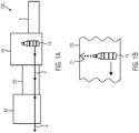
- Figures 1A , B show a first embodiment of the system 100 according to the invention.
- the system 100 comprises: a stretch blow molding device 10 for blowing a container 15, in particular a bottle; a cooling device 20 for cooling the blown container with dry ice particles or carbon dioxide gas; and a coating device 30 for coating the cooled container, in particular in the interior of the container; wherein the system comprises a transport path T for transporting the container from the stretch blow molding device 10 to the cooling device 20 and then to the coating device 30; and where the Coating device 30 has a discharge path A for discharging the coated container.
- a heating device heating furnace 5
- the preforms for the containers are heated to a processing temperature of about 80 to 100.degree.
- the preforms heated in this way are then subjected to the stretch blow molding process in the blow molding device 10.
- the cooling device 20 comprises a nozzle element 21 in order to direct a jet of the dry ice particles or the carbon dioxide gas onto the container, in particular onto a bottom area of the container (not shown), or (as shown here) into the container.
- a jet of cooling CO 2 (gas or snow) is directed into the interior of the container.
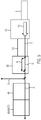
- Figures 2A, 2B , 2C show a second embodiment of the system 200 according to the invention.
- this system 200 corresponds to the first embodiment Figure 1 and with other components as described below.
- the flat arrow indicates the transport of a container 15.
- a coating path B on which the container is coated
- a bypass path U on which the containers are not coated. Both the coating path B and the bypass path U open into the diversion path A. If coating is not required or not desired, the container can be guided on the bypass path U past the actual coating device.
- the system further comprises a labeling device 40 for applying a label to the blown and cooled container and / or a printing device 70 for printing the blown and cooled container or a label; a filling device 50 for filling the blown and cooled container; and a closing device 60 for closing the filled container.
- the filling device 50 and the closing device 60 are here as a unit educated. After coating, the cooled containers can thus be provided with a label without deformation and with good adhesion due to the dry state or filled without deformation.
- Figure 3 shows a third embodiment of the system 300 according to the invention.
- This system 300 corresponds to a modification of the transport of the containers within the coating device 30 according to the second embodiment Figure 2 as described below.
- the coating device 30 has a branch Z1 for branching off coated containers to a further filling device.
- the system 100 according to the invention of the first embodiment can also be used for another filling system.
- Figure 4 shows a fourth embodiment of the system 400 according to the invention.
- This system 400 corresponds with a modification of the transport of the containers within the coating device 30 and / or in the cooling device 20 according to the second embodiment Figure 2 or the third embodiment 300 according to Figure 3 as described below.
- the coating device comprises a feed Z2 for feeding containers to be coated from a further stretch blow molding device.
- the coating device can also be used for containers from another stretch blow molding device.
- the supply of the containers can take place, for example, by means of air transport.
- a feed Z3 can take place from another stretch blow molding device onto the transport path T, so that containers can be cooled from there in the cooling device 20 and coated in the coating device 30.
- a feed Z3 can take place from another stretch blow molding device onto the transport path T, so that containers can be cooled from there in the cooling device 20 and coated in the coating device 30.
- Figure 5 shows a fifth embodiment of the system 500 according to the invention.
- This system 500 corresponds to the second embodiment according to FIG Figure 2 , the third embodiment 300 according to Figure 3 or the fourth embodiment 400 according to Figure 4 , but with the addition described below.
- the system 500 also contains a feed / branch Z4 between the coating device 30 and the labeling device 40. Via this, containers from another system can be introduced for labeling or containers coated in the coating device 30 can be fed to another system via the same route will.
Landscapes
- Physics & Mathematics (AREA)
- Thermal Sciences (AREA)
- Engineering & Computer Science (AREA)
- Manufacturing & Machinery (AREA)
- Mechanical Engineering (AREA)
- Blow-Moulding Or Thermoforming Of Plastics Or The Like (AREA)
- Containers Having Bodies Formed In One Piece (AREA)
- Labeling Devices (AREA)
Abstract
Description
- Die Erfindung betrifft ein System, das eine Streckblasvorrichtung zum Blasen eines Behälters; eine Kühlvorrichtung zum Kühlen des geblasenen Behälters; und eine Beschichtungsvorrichtung zum Beschichten des gekühlten Behälters umfasst. Weiterhin betrifft die Erfindung ein Verfahren zum Herstellen eines Behälters.
- In der Getränkeabfülltechnik sind sogenannte Streckblasmaschinen bekannt, in denen Vorformlinge aus Kunststoff unter Wärmeeinwirkung zu Behältern (insbesondere PET-Flaschen) geblasen werden. Die Behälter müssen in der Regel zur weiteren Verarbeitung gekühlt werden, beispielsweise um ein Verformen der Behälter beim Befüllen mit einem kohlensäurehaltigen Getränk unter Druck zu verhindern. Nach dem Stand der Technik kann die Kühlung der Behälter durch ein Besprühen oder Umspülen mit Wasser erfolgen.
- Weiterhin wird bei manchen Behältern aus Kunststoff im Innern eine Beschichtung aufgebracht, um ein Diffundieren von unerwünschten Stoffen aus dem Material des Vorformlings in das Getränk zu verhindern. Als Material für die Beschichtung kann SiO2 verwendet werden. Zum Beschichten muss der geblasene Behälter jedoch trocken sein, was einen weiteren Schritt des Trocknens der Behälter erfordert. Daher ist ein Kühlen mit Wasser gemäß Stand der Technik nachteilig.
- Aufgabe der Erfindung ist es, die oben genannten Nachteile zumindest teilweise zu mildern oder zu beseitigen.
- Die Aufgabe wird gelöst durch ein erfindungsgemäßes System nach Patentanspruch 1.
- Das erfindungsgemäße System umfasst: eine Streckblasvorrichtung zum Blasen eines Behälters, insbesondere einer Flasche; eine Kühlvorrichtung zum Kühlen des geblasenen Behälters mit Trockeneis-Partikeln oder Kohlendioxid-Gas; und eine Beschichtungsvorrichtung zum Beschichten des gekühlten Behälters, insbesondere im Innern des Behälters; wobei das System einen Transportpfad zum Transportieren des Behälters von der Streckblasvorrichtung zu der Kühlvorrichtung und anschließend zu der Beschichtungsvorrichtung umfasst; und wobei die Beschichtungsvorrichtung einen Ausleitpfad zum Ausleiten des beschichteten Behälters aufweist.
- Die erfindungsgemäße Vorrichtung hat den Vorteil, dass der Behälter aufgrund der Kühlung mit CO2-Gas oder -Partikeln trocken bleibt und problemlos beschichtet werden kann.
- Die erfindungsgemäße Vorrichtung kann wie folgt weitergebildet werden.
- Die Kühlvorrichtung kann ein Düsenelement umfassen, um einen Strahl der Trockeneis-Partikel oder des Kohlendioxid-Gases auf oder in den Behälter zu richten, insbesondere auf einen Bodenbereich des Behälters. Auf diese Weise kann ein Strahl des kühlenden CO2 als Gas oder als Partikel (CO2-Schneekristalle) gezielt auf die gewünschte Stelle gerichtet werden, insbesondere in das Innere des Behälters wenn noch eine Beschichtung aufzubringen ist.
- Innerhalb der Beschichtungsvorrichtung kann ein Beschichtungspfad, auf dem ein Beschichten des Behälters erfolgt, und ein Umgehungspfad, auf dem kein Beschichten der Behälter erfolgt, vorgesehen sein, wobei sowohl der Beschichtungspfad als auch der Umgehungspfad im Ausleitpfad münden. Auf diese Weise kann das gleiche System für verschiedene Behälter eingesetzt werden. Falls eine Beschichtung nicht erforderlich ist oder nicht gewünscht wird, kann der Behälter auf dem Umgehungspfad an der eigentlichen Beschichtungseinrichtung vorbeigeführt werden, jedoch über den gleichen Ausleitpfad, auf dem auch die beschichteten Behälter die Beschichtungsvorrichtung verlassen, wieder ausgeführt werden.
- Das System kann weiterhin umfassen: eine Etikettiervorrichtung zum Aufbringen eines Etiketts auf den geblasenen und gekühlten Behälter; und/oder eine Abfüllvorrichtung zum Befüllen des geblasenen und gekühlten Behälters und/oder eine Bedruckungsvorrichtung zum Bedrucken des geblasenen und gekühlten Behälters oder eines Etiketts; und/oder eine Verschließvorrichtung zum Verschließen des befüllten Behälters. Die gekühlten Behälter können somit anschließend verformungslos und durch den trockenen Zustand gut haftend mit einem Etikett versehen werden bzw. verformungslos befüllt werden. Die Abfüllvorrichtung und die Verschließvorrichtung können als Einheit mit beiden Funktionen ausgebildet sein.
- Die Beschichtungsvorrichtung kann eine Abzweigung zum Abzweigen von beschichteten Behältern zu einer weiteren Abfüllvorrichtung aufweisen. Somit kann das gleiche System für eine andere Abfüllanlage eingesetzt werden.
- Alternativ oder zusätzlich kann die Beschichtungsvorrichtung eine Zuführung zum Zuführen von zu beschichtenden Behältern von einer weiteren Streckblasvorrichtung aufweisen. Somit können Behälter von einer anderen Streckblasmaschine mit oder ohne Kühlung in die Beschichtungsvorrichtung eingebracht und beschichtet werden. Dies erhöht die Flexibilität des Systems.
- Die Kühlvorrichtung kann eine Zuführung zum Zuführen und Kühlen von Behältern von einer weiteren Streckblasvorrichtung aufweisen. Auf diese Weise kann die Kühlung mit der Kühlvorrichtung auch für Behälter von einer anderen Streckblasmaschine eingesetzt werden. Die erhöht ebenfalls die Flexibilität des Systems.
- Der Transportpfad kann eine Halterung zum Haltern des Behälters an einem Halsbereich des Behälters umfassen. Ein Haltern des Behälters (der Flasche) am Halsbereich (Neck) stellt eine vorteilhafte Art der Halterung dar, weil dadurch der Boden der Flasche gezielt und gut gekühlt werden kann.
- Die Streckblasvorrichtung, die Kühlvorrichtung und die Beschichtungsvorrichtung können gemeinsam als eine Einheit ausgebildet sein. Somit stellt das System eine kompakte Einheit dar, in die Vorformlinge für die Behälter eingeführt und beschichtete Behälter ausgeführt werden können. Aufgrund der Kühlung mit CO2 kann eine höhere Durchsatzrate als nach dem Stand der Technik mit Wasserkühlung erzielt werden.
- Die oben genannte Aufgabe wird weiterhin gelöst durch ein Verfahren nach Anspruch 9.
- Das erfindungsgemäße Verfahren zum Herstellen eines Behälters umfasst die Schritte: Blasen des Behälters in einer Streckblasvorrichtung; Kühlen des geblasenen Behälters mit Trockeneis-Partikeln oder Kohlendioxid-Gas in einer Kühlvorrichtung; Beschichten des gekühlten Behälters in einer Beschichtungsvorrichtung, insbesondere im Innern des Behälters; Transportieren des Behälters von der Streckblasvorrichtung zu der Kühlvorrichtung und anschließend zu der Beschichtungsvorrichtung auf einem Transportpfad; und Ausleiten des beschichteten Behälters aus der Beschichtungsvorrichtung auf einem Ausleitpfad.
- Die Vorteile des erfindungsgemäßen Verfahrens bzw. dessen Weiterbildungen entsprechen jenen in Bezug auf das erfindungsgemäße System bzw. dessen Weiterbildungen, und es wird daher auf obige Ausführungen verwiesen.
- Das erfindungsgemäße Verfahren kann folgendermaßen weitergebildet werden.
- Der Schritt des Kühlens kann einen Schritt des Richtens eines Strahls der Trockeneis-Partikel oder des Kohlendioxid-Gases auf oder in den Behälter, insbesondere auf einen Bodenbereich des Behälters, mit einem Düsenelement der Kühlvorrichtung umfassen.
- Das Beschichten des Behälters kann innerhalb der Beschichtungsvorrichtung auf einem Beschichtungspfad erfolgen und auf einem Umgehungspfad innerhalb der Beschichtungsvorrichtung kann kein Beschichten der Behälter erfolgen, wobei sowohl der Beschichtungspfad als auch der Umgehungspfad im Ausleitpfad münden können.
- Weiterhin kann wenigstens einer der folgenden weiteren Schritte durchgeführt werden: Aufbringen eines Etiketts auf den geblasenen und gekühlten Behälter mit einer Etikettiervorrichtung und/oder Bedrucken des geblasenen und gekühlten Behälters oder eines Etiketts mit einer Bedruckungsvorrichtung; und/oder Befüllen des geblasenen und gekühlten Behälters mit einer Abfüllvorrichtung; und/oder Verschließen des befüllten Behälters mit einer Verschließvorrichtung.
- Dies kann wiederum dahingehend weitergebildet werden, dass ein Abzweigen von beschichteten Behältern aus der Beschichtungsvorrichtung zu einer weiteren Abfüllvorrichtung und/oder ein Zuführen von zu beschichtenden Behältern zu der Beschichtungsvorrichtung von einer weiteren Streckblasvorrichtung vorgesehen sein kann.
- Das Verfahren kann den weiteren Schritten des Zuführens und Kühlens von Behältern von einer weiteren Streckblasvorrichtung zu der Kühlvorrichtung umfassen.
- Ein Haltern des Behälters auf dem Transportpfad kann an einem Halsbereich des Behälters vorgesehen sein.
- Weitere Merkmale und beispielhafte Ausführungsformen sowie Vorteile der vorliegenden Erfindung werden nachfolgend anhand der Zeichnung näher erläutert. Es versteht sich, dass diese Ausführungsform nicht den gesamten Bereich der vorliegenden Erfindung erschöpfen kann. Es versteht sich weiterhin, dass einige oder sämtliche der im Weiteren beschriebenen Merkmale auch auf andere Weise miteinander kombiniert werden können.
-
- Fig. 1 A,B
- zeigen eine erste Ausführungsform des erfindungsgemäßen Systems.
- Fig. 2 A,B,C
- zeigen eine zweite Ausführungsform des erfindungsgemäßen Systems.
- Fig. 3
- zeigt eine dritte Ausführungsform des erfindungsgemäßen Systems.
- Fig. 4
- zeigt eine vierte Ausführungsform des erfindungsgemäßen Systems.
- Fig. 5
- zeigt eine fünfte Ausführungsform des erfindungsgemäßen Systems.
- Erfindungsgemäß wird in einem Abschnitt aus einer Streckblasvorrichtung und einer Beschichtungsvorrichtung eine Trockenkühlung mit CO2-Schnee oder CO2-Gas der geblasenen Behälter vor deren Beschichtung durchgeführt.
- Die CO2-Schneepartikel bzw. Trockeneispartikel werden aus mit Druck beaufschlagtem, flüssigem CO2 erzeugt, beispielsweise aus einer Druckflasche, wobei aus einer Düse austretendes flüssiges CO2 unter atmosphärischem Druck expandiert und einen plötzlichen Phasenübergang in Trockeneispartikel (Trockeneis-Schneekristalle) durchläuft. Die austretenden Trockeneispartikel können beim Auftreffen auf die Oberfläche (etwa im Innenraum) eines Behälters schlagartig von der festen in die gasförmige Phase übergehen (Sublimation), wobei sich das Volumen um einen Faktor von einigen Hundert vergrößert. Dabei kontaktiert das entstehende kalte CO2-Gas die Oberfläche des Behälters und kühlt diesen. Weiterhin sublimiert an der Oberfläche auftreffender CO2-Schnee unter Entzug von Verdampfungswärme aus dem Behältermaterial. Alternativ kann aus der Druckflasche auch ein Strom aus kaltem CO2-Gas auf bzw. in den Behälter geleitet werden, ohne zuvor in Trockeneis-Schnee umgewandelt worden zu sein.
-
Figuren 1A , B zeigen eine erste Ausführungsform des erfindungsgemäßen Systems 100. - Das erfindungsgemäße System 100 umfasst: eine Streckblasvorrichtung 10 zum Blasen eines Behälters 15, insbesondere einer Flasche; eine Kühlvorrichtung 20 zum Kühlen des geblasenen Behälters mit Trockeneis-Partikeln oder Kohlendioxid-Gas; und eine Beschichtungsvorrichtung 30 zum Beschichten des gekühlten Behälters, insbesondere im Innern des Behälters; wobei das System einen Transportpfad T zum Transportieren des Behälters von der Streckblasvorrichtung 10 zu der Kühlvorrichtung 20 und anschließend zu der Beschichtungsvorrichtung 30 umfasst; und wobei die Beschichtungsvorrichtung 30 einen Ausleitpfad A zum Ausleiten des beschichteten Behälters aufweist. In einer Erhitzungsvorrichtung (Heizofen) 5 werden die Vorformlinge für die Behälter auf eine Verarbeitungstemperatur von etwa 80 bis 100 °C erhitzt. Die so erhitzten Vorformlinge werden dann in der Steckblasvorrichtung 10 dem Streckblasprozess unterworfen.
- Die Kühlvorrichtung 20 umfasst ein Düsenelement 21, um einen Strahl der Trockeneis-Partikel oder des Kohlendioxid-Gases auf den Behälter, insbesondere auf einen Bodenbereich des Behälters (nicht dargestellt), oder (wie hier gezeigt) in den Behälter zu richten. Ein Strahl des kühlenden CO2 (Gas oder Schnee) wird in das Innere des Behälters gerichtet.
-
Figuren 2A, 2B ,2C zeigen eine zweite Ausführungsform des erfindungsgemäßen Systems 200. - Dieses System 200 entspricht mit einer Abwandlung des Transports der Behälter innerhalb der Beschichtungsvorrichtung 30 der ersten Ausführungsform gemäß
Figur 1 und mit weiteren Komponenten, wie nachfolgend beschrieben wird. Hier und im Folgenden zeigt der flächige Pfeil den Transport eines Behälters 15 an. - Innerhalb der Beschichtungsvorrichtung 30 gibt es einen Beschichtungspfad B, auf dem ein Beschichten des Behälters erfolgt, und einen Umgehungspfad U, auf dem kein Beschichten der Behälter erfolgt. Sowohl der Beschichtungspfad B als auch der Umgehungspfad U münden im Ausleitpfad A. Falls eine Beschichtung nicht erforderlich ist oder nicht gewünscht wird, kann der Behälter auf dem Umgehungspfad U an der eigentlichen Beschichtungseinrichtung vorbeigeführt werden.
- Das System umfasst in dieser Ausführungsform weiterhin eine Etikettiervorrichtung 40 zum Aufbringen eines Etiketts auf den geblasenen und gekühlten Behälter und/oder eine Bedruckungsvorrichtung 70 zum Bedrucken des geblasenen und gekühlten Behälters oder eines Etiketts; eine Abfüllvorrichtung 50 zum Befüllen des geblasenen und gekühlten Behälters; und eine Verschließvorrichtung 60 zum Verschließen des befüllten Behälters. Die Abfüllvorrichtung 50 und die Verschließvorrichtung 60 sind hier als Einheit ausgebildet. Die gekühlten Behälter können somit nach der Beschichtung verformungslos und durch den trockenen Zustand gut haftend mit einem Etikett versehen werden bzw. verformungslos befüllt werden.
-
Figur 3 zeigt eine dritte Ausführungsform des erfindungsgemäßen Systems 300. - Dieses System 300 entspricht mit einer Abwandlung des Transports der Behälter innerhalb der Beschichtungsvorrichtung 30 der zweiten Ausführungsform gemäß
Figur 2 , wie nachfolgend beschrieben wird. - Die Beschichtungsvorrichtung 30 weist in dieser Ausführungsform eine Abzweigung Z1 zum Abzweigen von beschichteten Behältern zu einer weiteren Abfüllvorrichtung auf. Auf diese Weise kann das erfindungsgemäße System 100 der ersten Ausführungsform zusätzlich auch für eine andere Abfüllanlage eingesetzt werden.
-
Figur 4 zeigt eine vierte Ausführungsform des erfindungsgemäßen Systems 400. - Dieses System 400 entspricht mit einer Abwandlung des Transports der Behälter innerhalb der Beschichtungsvorrichtung 30 und/oder in der Kühlvorrichtung 20 der zweiten Ausführungsform gemäß
Figur 2 oder der dritten Ausführungsform 300 gemäßFigur 3 , wie nachfolgend beschrieben wird. - Die Beschichtungsvorrichtung umfasst in dieser Ausführungsform 400 eine Zuführung Z2 zum Zuführen von zu beschichtenden Behältern von einer weiteren Streckblasvorrichtung auf. Auf diese Weise kann die Beschichtungsvorrichtung auch für Behälter von einer anderen Streckblasvorrichtung eingesetzt werden. Die Zuleitung der Behälter kann beispielsweise mittels Lufttransport erfolgen.
- Alternativ oder zusätzlich kann eine Zuführung Z3 von einer anderen Streckblasvorrichtung auf den Transportpfad T erfolgen, so dass Behälter von dort in der Kühlvorrichtung 20 gekühlt und in der Beschichtungsvorrichtung 30 beschichtet werden können. Auf diese Weise ist es beispielsweise möglich, die Streckblasvorrichtung 10 auf eine andere Behälter-/Flaschensorte umzurüsten, während gleichzeitig der Betrieb des Kühlens und Beschichtens von Behältern von der anderen Streckblasvorrichtung erfolgt.
-
Figur 5 zeigt eine fünfte Ausführungsform des erfindungsgemäßen Systems 500. - Dieses System 500 entspricht der zweiten Ausführungsform gemäß
Figur 2 , der dritten Ausführungsform 300 gemäßFigur 3 oder der vierten Ausführungsform 400 gemäßFigur 4 , jedoch mit nachfolgend beschriebener Ergänzung. - In dieser fünften Ausführungsform enthält das System 500 weiterhin eine Zuführung / Abzweigung Z4 zwischen der Beschichtungsvorrichtung 30 und der Etikettiervorrichtung 40. Darüber können Behälter von einer anderen Anlage zum Etikettieren eingebracht werden oder in der Beschichtungsvorrichtung 30 beschichtete Behälter können über den gleichen Weg einer anderen Anlage zugeführt werden.
- Die dargestellten Ausführungsformen sind lediglich beispielhaft und der vollständige Umfang der vorliegenden Erfindung wird durch die Ansprüche definiert.
Claims (15)
- System (100), umfassend:eine Streckblasvorrichtung (10) zum Blasen eines Behälters (15), insbesondere einer Flasche;eine Kühlvorrichtung (20) zum Kühlen des geblasenen Behälters (15) mit Trockeneis-Partikeln oder Kohlendioxid-Gas; undeine Beschichtungsvorrichtung (30) zum Beschichten des gekühlten Behälters (15), insbesondere im Innern des Behälters;wobei das System einen Transportpfad zum Transportieren des Behälters von der Streckblasvorrichtung (10) zu der Kühlvorrichtung (20) und anschließend zu der Beschichtungsvorrichtung (30) umfasst; undwobei die Beschichtungsvorrichtung (30) einen Ausleitpfad zum Ausleiten des beschichteten Behälters (15) aufweist.
- System nach Anspruch 1, wobei die Kühlvorrichtung ein Düsenelement (21) umfasst, um einen Strahl der Trockeneis-Partikel oder des Kohlendioxid-Gases auf oder in den Behälter zu richten, insbesondere auf einen Bodenbereich des Behälters.
- System nach Anspruch 1 oder 2, wobei innerhalb der Beschichtungsvorrichtung ein Beschichtungspfad, auf dem ein Beschichten des Behälters erfolgt, und ein Umgehungspfad, auf dem kein Beschichten der Behälter erfolgt, vorgesehen sind, wobei sowohl der Beschichtungspfad als auch der Umgehungspfad im Ausleitpfad münden.
- System nach einem der Ansprüche 1 bis 3, wobei das System weiterhin umfasst:eine Etikettiervorrichtung (40) zum Aufbringen eines Etiketts auf den geblasenen und gekühlten Behälter und/oder eine Bedruckungsvorrichtung (70) zum Bedrucken des geblasenen und gekühlten Behälters oder eines Etiketts; und/odereine Abfüllvorrichtung (50) zum Befüllen des geblasenen und gekühlten Behälters; und/odereine Verschließvorrichtung (60) zum Verschließen des befüllten Behälters.
- System nach Anspruch 4, wobei die Beschichtungsvorrichtung eine Abzweigung zum Abzweigen von beschichteten Behältern zu einer weiteren Abfüllvorrichtung aufweist und/oder wobei die Beschichtungsvorrichtung eine Zuführung zum Zuführen von zu beschichtenden Behältern von einer weiteren Streckblasvorrichtung aufweist.
- System nach einem der Ansprüche 1 bis 5, wobei die Kühlvorrichtung eine Zuführung zum Zuführen und Kühlen von Behältern von einer weiteren Streckblasvorrichtung aufweist.
- System nach einem der Ansprüche 1 bis 6, wobei der Transportpfad eine Halterung zum Haltern des Behälters an einem Halsbereich des Behälters umfasst.
- System nach einem der Ansprüche 1 bis 7, wobei die Streckblasvorrichtung, die Kühlvorrichtung und die Beschichtungsvorrichtung gemeinsam als eine Einheit ausgebildet sind.
- Verfahren zum Herstellen eines Behälters, umfassend die Schritte:Blasen des Behälters in einer Streckblasvorrichtung (10);Kühlen des geblasenen Behälters mit Trockeneis-Partikeln oder Kohlendioxid-Gas in einer Kühlvorrichtung (20);Beschichten des gekühlten Behälters in einer Beschichtungsvorrichtung (30), insbesondere im Innern des Behälters;Transportieren des Behälters von der Streckblasvorrichtung (10) zu der Kühlvorrichtung (20) und anschließend zu der Beschichtungsvorrichtung (30) auf einem Transportpfad; undAusleiten des beschichteten Behälters (15) aus der Beschichtungsvorrichtung (30) auf einem Ausleitpfad.
- Verfahren nach Anspruch 9, wobei der Schritt des Kühlens einen Schritt des Richtens eines Strahls der Trockeneis-Partikel oder des Kohlendioxid-Gases auf oder in den Behälter, insbesondere auf einen Bodenbereich des Behälters, mit einem Düsenelement (21) der Kühlvorrichtung umfasst.
- Verfahren nach Anspruch 9 oder 10, wobei das Beschichten des Behälters innerhalb der Beschichtungsvorrichtung auf einem Beschichtungspfad erfolgt und auf einem Umgehungspfad innerhalb der Beschichtungsvorrichtung kein Beschichten der Behälter erfolgt, wobei sowohl der Beschichtungspfad als auch der Umgehungspfad im Ausleitpfad münden.
- Verfahren nach einem der Ansprüche 9 bis 11, wobei wenigstens einer der folgenden weiteren Schritte durchgeführt wird:Aufbringen eines Etiketts auf den geblasenen und gekühlten Behälter mit einer Etikettiervorrichtung (40) und/oder Bedrucken des geblasenen und gekühlten Behälters oder eines Etiketts mit einer Bedruckungsvorrichtung (70); und/oderBefüllen des geblasenen und gekühlten Behälters mit einer Abfüllvorrichtung (50); und/oderVerschließen des befüllten Behälters mit einer Verschließvorrichtung (60).
- Verfahren nach Anspruch 12, weiterhin umfassend den Schritt:
Abzweigen von beschichteten Behältern aus der Beschichtungsvorrichtung zu einer weiteren Abfüllvorrichtung und/oder Zuführen von zu beschichtenden Behältern zu der Beschichtungsvorrichtung von einer weiteren Streckblasvorrichtung. - Verfahren nach einem der Ansprüche 9 bis 13, mit den weiteren Schritten des Zuführens und Kühlens von Behältern von einer weiteren Streckblasvorrichtung zu der Kühlvorrichtung.
- Verfahren nach einem der Ansprüche 9 bis 14, wobei ein Haltern des Behälters auf dem Transportpfad an einem Halsbereich des Behälters vorgesehen ist.
Applications Claiming Priority (1)
| Application Number | Priority Date | Filing Date | Title |
|---|---|---|---|
| DE102019120274.4A DE102019120274A1 (de) | 2019-07-26 | 2019-07-26 | System und Verfahren zum Herstellen eines Behälters |
Publications (2)
| Publication Number | Publication Date |
|---|---|
| EP3769933A1 true EP3769933A1 (de) | 2021-01-27 |
| EP3769933B1 EP3769933B1 (de) | 2022-04-27 |
Family
ID=70857015
Family Applications (1)
| Application Number | Title | Priority Date | Filing Date |
|---|---|---|---|
| EP20176405.7A Active EP3769933B1 (de) | 2019-07-26 | 2020-05-26 | System und verfahren zum herstellen eines behälters |
Country Status (3)
| Country | Link |
|---|---|
| EP (1) | EP3769933B1 (de) |
| CN (1) | CN112297394B (de) |
| DE (1) | DE102019120274A1 (de) |
Citations (3)
| Publication number | Priority date | Publication date | Assignee | Title |
|---|---|---|---|---|
| FR2405809A1 (fr) * | 1977-06-30 | 1979-05-11 | Air Liquide | Procede de refroidissement d'un corps creux en materiau thermoplastique et dispositif de formage de corps creux en materiau thermoplastique |
| US20120100238A1 (en) * | 2010-10-26 | 2012-04-26 | Krones Ag | Blow Moulding Machine in a Modular Design |
| US9725293B2 (en) * | 2005-11-29 | 2017-08-08 | Petainer Lidkoping Ab | System and method for distribution and dispensing of beverages |
Family Cites Families (6)
| Publication number | Priority date | Publication date | Assignee | Title |
|---|---|---|---|---|
| FR3034037B1 (fr) * | 2015-03-25 | 2017-03-17 | Sidel Participations | Procede de fabrication d'un emballage comprenant un recipient imprime directement et traite par plasma |
| CN106366588B (zh) * | 2016-08-29 | 2018-09-07 | 浙江比例包装股份有限公司 | 气体阻隔易脱模的全生物降解饮料瓶的生产方法 |
| CN107775946A (zh) * | 2016-08-31 | 2018-03-09 | 岱纳包装(天津)有限公司 | 一种人机交互智能闭环控制全自动吹塑生产线及工艺 |
| FR3057198B1 (fr) * | 2016-10-12 | 2018-10-05 | Sidel Participations | Installation de fabrication de recipients comportant une roue de contournement d'une station de revetement |
| DE102017120762A1 (de) * | 2017-09-08 | 2019-03-14 | Krones Ag | Flexible Anlage zum Behandeln von Behältnissen |
| JP7016888B2 (ja) * | 2017-12-25 | 2022-02-07 | サントリーホールディングス株式会社 | プリフォームコーティング装置 |
-
2019
- 2019-07-26 DE DE102019120274.4A patent/DE102019120274A1/de active Pending
-
2020
- 2020-05-26 EP EP20176405.7A patent/EP3769933B1/de active Active
- 2020-07-23 CN CN202010715712.7A patent/CN112297394B/zh active Active
Patent Citations (3)
| Publication number | Priority date | Publication date | Assignee | Title |
|---|---|---|---|---|
| FR2405809A1 (fr) * | 1977-06-30 | 1979-05-11 | Air Liquide | Procede de refroidissement d'un corps creux en materiau thermoplastique et dispositif de formage de corps creux en materiau thermoplastique |
| US9725293B2 (en) * | 2005-11-29 | 2017-08-08 | Petainer Lidkoping Ab | System and method for distribution and dispensing of beverages |
| US20120100238A1 (en) * | 2010-10-26 | 2012-04-26 | Krones Ag | Blow Moulding Machine in a Modular Design |
Also Published As
| Publication number | Publication date |
|---|---|
| EP3769933B1 (de) | 2022-04-27 |
| CN112297394B (zh) | 2022-10-04 |
| DE102019120274A1 (de) | 2021-01-28 |
| CN112297394A (zh) | 2021-02-02 |
Similar Documents
| Publication | Publication Date | Title |
|---|---|---|
| DE102008057403A1 (de) | Vorrichtung und Verfahren zum Herstellen von Kunststoffbehältnissen | |
| EP2595790B1 (de) | Verfahren und vorrichtung zum sterilisieren von vorformlingen | |
| EP2850029B2 (de) | Behältnisherstellungsanlage mit bodenkühlung der behältnisse | |
| WO2012130197A1 (de) | Verfahren zum sterilisieren sowie vorrichtung zur blasformung von behältern | |
| EP3423255A1 (de) | Anlage und verfahren zum behandeln von kunststoffvorformlingen mit luftförderer oder transportshuttle | |
| EP2357066A2 (de) | Verfahren und Anlage zum Herstellen von Behälter-Preforms | |
| EP2845717A1 (de) | Verfahren und Vorrichtung zur Bodennachkühlung | |
| DE102009060655A1 (de) | Kühleinrichtung zum Stabilisieren einer Behältnisstruktur | |
| EP2113368A2 (de) | Vorrichtung zum Blasformen | |
| DE102012102357A1 (de) | Preformtransport mit Auswurfmöglichkeit | |
| EP3769933B1 (de) | System und verfahren zum herstellen eines behälters | |
| DE4325559C2 (de) | Verfahren zur Herstellung von Blasformteilen aus Kunststoff | |
| DE102017103438A1 (de) | Verfahren und Vorrichtung zur Trocknung von auf einem rotierenden Blasrad angeordneten Blasformen zur Vermeidung von Kondenswasserbildung | |
| DE102011075171A1 (de) | Preferential Heating mit Plasma | |
| DE2223580C3 (de) | Verfahren und Vorrichtung zum Herstellen von Hohlkörpern aus Kunststoff nach dem Blasverfahren | |
| EP1566258A2 (de) | Vorrichtung zur Bearbeitung von Werkstücken | |
| CH616875A5 (en) | Process and device for producing a plastic container by inflating a parison | |
| DE102020130007A1 (de) | Verfahren zum Herstellen von Kunststoffflaschen und Streckblasmaschine | |
| DE102023133922A1 (de) | Anlage zum Behandeln von Behältern | |
| DE102019108683A1 (de) | Verfahren und Vorrichtung zum Verschließen von Behältern mit Behälterverschlüssen | |
| DE102023101887A1 (de) | Vorrichtung zum Verdampfen eines flüssigen Sterilisationsmittels sowie Verfahren zum Reinigen der Vorrichtung | |
| DE102023108574A1 (de) | Vorrichtung und Verfahren zum Herstellen von Behältern aus Vorformlingen | |
| EP1473139A1 (de) | Verfahren und Vorrichtung zur Blasformung von Behältern | |
| CH695940A5 (de) | Verfahren und Vorrichtung zur Herstellung und Abfüllung von Kunststoffflaschen. | |
| EP4464502A1 (de) | Behälterherstellungsmaschine und verfahren zum herstellen von behältern aus vorformlingen |
Legal Events
| Date | Code | Title | Description |
|---|---|---|---|
| PUAI | Public reference made under article 153(3) epc to a published international application that has entered the european phase |
Free format text: ORIGINAL CODE: 0009012 |
|
| STAA | Information on the status of an ep patent application or granted ep patent |
Free format text: STATUS: THE APPLICATION HAS BEEN PUBLISHED |
|
| AK | Designated contracting states |
Kind code of ref document: A1 Designated state(s): AL AT BE BG CH CY CZ DE DK EE ES FI FR GB GR HR HU IE IS IT LI LT LU LV MC MK MT NL NO PL PT RO RS SE SI SK SM TR |
|
| AX | Request for extension of the european patent |
Extension state: BA ME |
|
| STAA | Information on the status of an ep patent application or granted ep patent |
Free format text: STATUS: REQUEST FOR EXAMINATION WAS MADE |
|
| 17P | Request for examination filed |
Effective date: 20210630 |
|
| RBV | Designated contracting states (corrected) |
Designated state(s): AL AT BE BG CH CY CZ DE DK EE ES FI FR GB GR HR HU IE IS IT LI LT LU LV MC MK MT NL NO PL PT RO RS SE SI SK SM TR |
|
| GRAP | Despatch of communication of intention to grant a patent |
Free format text: ORIGINAL CODE: EPIDOSNIGR1 |
|
| STAA | Information on the status of an ep patent application or granted ep patent |
Free format text: STATUS: GRANT OF PATENT IS INTENDED |
|
| RIC1 | Information provided on ipc code assigned before grant |
Ipc: B29L 31/00 20060101ALN20211019BHEP Ipc: B29K 67/00 20060101ALN20211019BHEP Ipc: B29C 49/06 20060101ALN20211019BHEP Ipc: B29C 49/66 20060101ALI20211019BHEP Ipc: B29C 49/42 20060101AFI20211019BHEP |
|
| RIC1 | Information provided on ipc code assigned before grant |
Ipc: B29L 31/00 20060101ALN20211026BHEP Ipc: B29K 67/00 20060101ALN20211026BHEP Ipc: B29C 49/06 20060101ALN20211026BHEP Ipc: B29C 49/66 20060101ALI20211026BHEP Ipc: B29C 49/42 20060101AFI20211026BHEP |
|
| INTG | Intention to grant announced |
Effective date: 20211111 |
|
| GRAS | Grant fee paid |
Free format text: ORIGINAL CODE: EPIDOSNIGR3 |
|
| GRAA | (expected) grant |
Free format text: ORIGINAL CODE: 0009210 |
|
| STAA | Information on the status of an ep patent application or granted ep patent |
Free format text: STATUS: THE PATENT HAS BEEN GRANTED |
|
| AK | Designated contracting states |
Kind code of ref document: B1 Designated state(s): AL AT BE BG CH CY CZ DE DK EE ES FI FR GB GR HR HU IE IS IT LI LT LU LV MC MK MT NL NO PL PT RO RS SE SI SK SM TR |
|
| REG | Reference to a national code |
Ref country code: GB Ref legal event code: FG4D Free format text: NOT ENGLISH |
|
| REG | Reference to a national code |
Ref country code: CH Ref legal event code: EP |
|
| REG | Reference to a national code |
Ref country code: DE Ref legal event code: R096 Ref document number: 502020000997 Country of ref document: DE |
|
| REG | Reference to a national code |
Ref country code: AT Ref legal event code: REF Ref document number: 1486605 Country of ref document: AT Kind code of ref document: T Effective date: 20220515 |
|
| REG | Reference to a national code |
Ref country code: IE Ref legal event code: FG4D Free format text: LANGUAGE OF EP DOCUMENT: GERMAN |
|
| REG | Reference to a national code |
Ref country code: LT Ref legal event code: MG9D |
|
| REG | Reference to a national code |
Ref country code: NL Ref legal event code: MP Effective date: 20220427 |
|
| PG25 | Lapsed in a contracting state [announced via postgrant information from national office to epo] |
Ref country code: NL Free format text: LAPSE BECAUSE OF FAILURE TO SUBMIT A TRANSLATION OF THE DESCRIPTION OR TO PAY THE FEE WITHIN THE PRESCRIBED TIME-LIMIT Effective date: 20220427 |
|
| PG25 | Lapsed in a contracting state [announced via postgrant information from national office to epo] |
Ref country code: SE Free format text: LAPSE BECAUSE OF FAILURE TO SUBMIT A TRANSLATION OF THE DESCRIPTION OR TO PAY THE FEE WITHIN THE PRESCRIBED TIME-LIMIT Effective date: 20220427 Ref country code: PT Free format text: LAPSE BECAUSE OF FAILURE TO SUBMIT A TRANSLATION OF THE DESCRIPTION OR TO PAY THE FEE WITHIN THE PRESCRIBED TIME-LIMIT Effective date: 20220829 Ref country code: NO Free format text: LAPSE BECAUSE OF FAILURE TO SUBMIT A TRANSLATION OF THE DESCRIPTION OR TO PAY THE FEE WITHIN THE PRESCRIBED TIME-LIMIT Effective date: 20220727 Ref country code: LT Free format text: LAPSE BECAUSE OF FAILURE TO SUBMIT A TRANSLATION OF THE DESCRIPTION OR TO PAY THE FEE WITHIN THE PRESCRIBED TIME-LIMIT Effective date: 20220427 Ref country code: HR Free format text: LAPSE BECAUSE OF FAILURE TO SUBMIT A TRANSLATION OF THE DESCRIPTION OR TO PAY THE FEE WITHIN THE PRESCRIBED TIME-LIMIT Effective date: 20220427 Ref country code: GR Free format text: LAPSE BECAUSE OF FAILURE TO SUBMIT A TRANSLATION OF THE DESCRIPTION OR TO PAY THE FEE WITHIN THE PRESCRIBED TIME-LIMIT Effective date: 20220728 Ref country code: FI Free format text: LAPSE BECAUSE OF FAILURE TO SUBMIT A TRANSLATION OF THE DESCRIPTION OR TO PAY THE FEE WITHIN THE PRESCRIBED TIME-LIMIT Effective date: 20220427 Ref country code: BG Free format text: LAPSE BECAUSE OF FAILURE TO SUBMIT A TRANSLATION OF THE DESCRIPTION OR TO PAY THE FEE WITHIN THE PRESCRIBED TIME-LIMIT Effective date: 20220727 |
|
| PG25 | Lapsed in a contracting state [announced via postgrant information from national office to epo] |
Ref country code: RS Free format text: LAPSE BECAUSE OF FAILURE TO SUBMIT A TRANSLATION OF THE DESCRIPTION OR TO PAY THE FEE WITHIN THE PRESCRIBED TIME-LIMIT Effective date: 20220427 Ref country code: PL Free format text: LAPSE BECAUSE OF FAILURE TO SUBMIT A TRANSLATION OF THE DESCRIPTION OR TO PAY THE FEE WITHIN THE PRESCRIBED TIME-LIMIT Effective date: 20220427 Ref country code: LV Free format text: LAPSE BECAUSE OF FAILURE TO SUBMIT A TRANSLATION OF THE DESCRIPTION OR TO PAY THE FEE WITHIN THE PRESCRIBED TIME-LIMIT Effective date: 20220427 Ref country code: IS Free format text: LAPSE BECAUSE OF FAILURE TO SUBMIT A TRANSLATION OF THE DESCRIPTION OR TO PAY THE FEE WITHIN THE PRESCRIBED TIME-LIMIT Effective date: 20220827 |
|
| REG | Reference to a national code |
Ref country code: BE Ref legal event code: MM Effective date: 20220531 |
|
| REG | Reference to a national code |
Ref country code: DE Ref legal event code: R097 Ref document number: 502020000997 Country of ref document: DE |
|
| PG25 | Lapsed in a contracting state [announced via postgrant information from national office to epo] |
Ref country code: SM Free format text: LAPSE BECAUSE OF FAILURE TO SUBMIT A TRANSLATION OF THE DESCRIPTION OR TO PAY THE FEE WITHIN THE PRESCRIBED TIME-LIMIT Effective date: 20220427 Ref country code: SK Free format text: LAPSE BECAUSE OF FAILURE TO SUBMIT A TRANSLATION OF THE DESCRIPTION OR TO PAY THE FEE WITHIN THE PRESCRIBED TIME-LIMIT Effective date: 20220427 Ref country code: RO Free format text: LAPSE BECAUSE OF FAILURE TO SUBMIT A TRANSLATION OF THE DESCRIPTION OR TO PAY THE FEE WITHIN THE PRESCRIBED TIME-LIMIT Effective date: 20220427 Ref country code: MC Free format text: LAPSE BECAUSE OF FAILURE TO SUBMIT A TRANSLATION OF THE DESCRIPTION OR TO PAY THE FEE WITHIN THE PRESCRIBED TIME-LIMIT Effective date: 20220427 Ref country code: LU Free format text: LAPSE BECAUSE OF NON-PAYMENT OF DUE FEES Effective date: 20220526 Ref country code: ES Free format text: LAPSE BECAUSE OF FAILURE TO SUBMIT A TRANSLATION OF THE DESCRIPTION OR TO PAY THE FEE WITHIN THE PRESCRIBED TIME-LIMIT Effective date: 20220427 Ref country code: EE Free format text: LAPSE BECAUSE OF FAILURE TO SUBMIT A TRANSLATION OF THE DESCRIPTION OR TO PAY THE FEE WITHIN THE PRESCRIBED TIME-LIMIT Effective date: 20220427 Ref country code: DK Free format text: LAPSE BECAUSE OF FAILURE TO SUBMIT A TRANSLATION OF THE DESCRIPTION OR TO PAY THE FEE WITHIN THE PRESCRIBED TIME-LIMIT Effective date: 20220427 Ref country code: CZ Free format text: LAPSE BECAUSE OF FAILURE TO SUBMIT A TRANSLATION OF THE DESCRIPTION OR TO PAY THE FEE WITHIN THE PRESCRIBED TIME-LIMIT Effective date: 20220427 |
|
| PLBE | No opposition filed within time limit |
Free format text: ORIGINAL CODE: 0009261 |
|
| STAA | Information on the status of an ep patent application or granted ep patent |
Free format text: STATUS: NO OPPOSITION FILED WITHIN TIME LIMIT |
|
| PG25 | Lapsed in a contracting state [announced via postgrant information from national office to epo] |
Ref country code: AL Free format text: LAPSE BECAUSE OF FAILURE TO SUBMIT A TRANSLATION OF THE DESCRIPTION OR TO PAY THE FEE WITHIN THE PRESCRIBED TIME-LIMIT Effective date: 20220427 |
|
| 26N | No opposition filed |
Effective date: 20230130 |
|
| PG25 | Lapsed in a contracting state [announced via postgrant information from national office to epo] |
Ref country code: IE Free format text: LAPSE BECAUSE OF NON-PAYMENT OF DUE FEES Effective date: 20220526 |
|
| PG25 | Lapsed in a contracting state [announced via postgrant information from national office to epo] |
Ref country code: SI Free format text: LAPSE BECAUSE OF FAILURE TO SUBMIT A TRANSLATION OF THE DESCRIPTION OR TO PAY THE FEE WITHIN THE PRESCRIBED TIME-LIMIT Effective date: 20220427 Ref country code: BE Free format text: LAPSE BECAUSE OF NON-PAYMENT OF DUE FEES Effective date: 20220531 |
|
| P01 | Opt-out of the competence of the unified patent court (upc) registered |
Effective date: 20230523 |
|
| REG | Reference to a national code |
Ref country code: CH Ref legal event code: PL |
|
| PG25 | Lapsed in a contracting state [announced via postgrant information from national office to epo] |
Ref country code: LI Free format text: LAPSE BECAUSE OF NON-PAYMENT OF DUE FEES Effective date: 20230531 Ref country code: CH Free format text: LAPSE BECAUSE OF NON-PAYMENT OF DUE FEES Effective date: 20230531 |
|
| PG25 | Lapsed in a contracting state [announced via postgrant information from national office to epo] |
Ref country code: MK Free format text: LAPSE BECAUSE OF FAILURE TO SUBMIT A TRANSLATION OF THE DESCRIPTION OR TO PAY THE FEE WITHIN THE PRESCRIBED TIME-LIMIT Effective date: 20220427 Ref country code: CY Free format text: LAPSE BECAUSE OF FAILURE TO SUBMIT A TRANSLATION OF THE DESCRIPTION OR TO PAY THE FEE WITHIN THE PRESCRIBED TIME-LIMIT Effective date: 20220427 |
|
| PG25 | Lapsed in a contracting state [announced via postgrant information from national office to epo] |
Ref country code: HU Free format text: LAPSE BECAUSE OF FAILURE TO SUBMIT A TRANSLATION OF THE DESCRIPTION OR TO PAY THE FEE WITHIN THE PRESCRIBED TIME-LIMIT; INVALID AB INITIO Effective date: 20200526 |
|
| PG25 | Lapsed in a contracting state [announced via postgrant information from national office to epo] |
Ref country code: TR Free format text: LAPSE BECAUSE OF FAILURE TO SUBMIT A TRANSLATION OF THE DESCRIPTION OR TO PAY THE FEE WITHIN THE PRESCRIBED TIME-LIMIT Effective date: 20220427 |
|
| PG25 | Lapsed in a contracting state [announced via postgrant information from national office to epo] |
Ref country code: MT Free format text: LAPSE BECAUSE OF FAILURE TO SUBMIT A TRANSLATION OF THE DESCRIPTION OR TO PAY THE FEE WITHIN THE PRESCRIBED TIME-LIMIT Effective date: 20220427 |
|
| PG25 | Lapsed in a contracting state [announced via postgrant information from national office to epo] |
Ref country code: BG Free format text: LAPSE BECAUSE OF FAILURE TO SUBMIT A TRANSLATION OF THE DESCRIPTION OR TO PAY THE FEE WITHIN THE PRESCRIBED TIME-LIMIT Effective date: 20220427 |
|
| PG25 | Lapsed in a contracting state [announced via postgrant information from national office to epo] |
Ref country code: BG Free format text: LAPSE BECAUSE OF FAILURE TO SUBMIT A TRANSLATION OF THE DESCRIPTION OR TO PAY THE FEE WITHIN THE PRESCRIBED TIME-LIMIT Effective date: 20220427 |
|
| GBPC | Gb: european patent ceased through non-payment of renewal fee |
Effective date: 20240526 |
|
| PG25 | Lapsed in a contracting state [announced via postgrant information from national office to epo] |
Ref country code: GB Free format text: LAPSE BECAUSE OF NON-PAYMENT OF DUE FEES Effective date: 20240526 |
|
| PGFP | Annual fee paid to national office [announced via postgrant information from national office to epo] |
Ref country code: DE Payment date: 20250402 Year of fee payment: 6 |
|
| PGFP | Annual fee paid to national office [announced via postgrant information from national office to epo] |
Ref country code: IT Payment date: 20250422 Year of fee payment: 6 |
|
| PGFP | Annual fee paid to national office [announced via postgrant information from national office to epo] |
Ref country code: FR Payment date: 20250401 Year of fee payment: 6 |
|
| PGFP | Annual fee paid to national office [announced via postgrant information from national office to epo] |
Ref country code: AT Payment date: 20250721 Year of fee payment: 5 |