EP3769729B1 - Vorrichtung zur intraokularen verabreichung zur intraokularen verabreichung einer substanz, zum beispiel eines medikaments, in ein menschliches oder tierisches auge - Google Patents
Vorrichtung zur intraokularen verabreichung zur intraokularen verabreichung einer substanz, zum beispiel eines medikaments, in ein menschliches oder tierisches auge Download PDFInfo
- Publication number
- EP3769729B1 EP3769729B1 EP19206855.9A EP19206855A EP3769729B1 EP 3769729 B1 EP3769729 B1 EP 3769729B1 EP 19206855 A EP19206855 A EP 19206855A EP 3769729 B1 EP3769729 B1 EP 3769729B1
- Authority
- EP
- European Patent Office
- Prior art keywords
- base structure
- eye
- intraocular administration
- administration device
- elliptical
- Prior art date
- Legal status (The legal status is an assumption and is not a legal conclusion. Google has not performed a legal analysis and makes no representation as to the accuracy of the status listed.)
- Active
Links
Images


Classifications
-
- A—HUMAN NECESSITIES
- A61—MEDICAL OR VETERINARY SCIENCE; HYGIENE
- A61F—FILTERS IMPLANTABLE INTO BLOOD VESSELS; PROSTHESES; DEVICES PROVIDING PATENCY TO, OR PREVENTING COLLAPSING OF, TUBULAR STRUCTURES OF THE BODY, e.g. STENTS; ORTHOPAEDIC, NURSING OR CONTRACEPTIVE DEVICES; FOMENTATION; TREATMENT OR PROTECTION OF EYES OR EARS; BANDAGES, DRESSINGS OR ABSORBENT PADS; FIRST-AID KITS
- A61F9/00—Methods or devices for treatment of the eyes; Devices for putting in contact-lenses; Devices to correct squinting; Apparatus to guide the blind; Protective devices for the eyes, carried on the body or in the hand
- A61F9/0008—Introducing ophthalmic products into the ocular cavity or retaining products therein
- A61F9/0017—Introducing ophthalmic products into the ocular cavity or retaining products therein implantable in, or in contact with, the eye, e.g. ocular inserts
-
- A—HUMAN NECESSITIES
- A61—MEDICAL OR VETERINARY SCIENCE; HYGIENE
- A61F—FILTERS IMPLANTABLE INTO BLOOD VESSELS; PROSTHESES; DEVICES PROVIDING PATENCY TO, OR PREVENTING COLLAPSING OF, TUBULAR STRUCTURES OF THE BODY, e.g. STENTS; ORTHOPAEDIC, NURSING OR CONTRACEPTIVE DEVICES; FOMENTATION; TREATMENT OR PROTECTION OF EYES OR EARS; BANDAGES, DRESSINGS OR ABSORBENT PADS; FIRST-AID KITS
- A61F9/00—Methods or devices for treatment of the eyes; Devices for putting in contact-lenses; Devices to correct squinting; Apparatus to guide the blind; Protective devices for the eyes, carried on the body or in the hand
- A61F9/0008—Introducing ophthalmic products into the ocular cavity or retaining products therein
- A61F9/0026—Ophthalmic product dispenser attachments to facilitate positioning near the eye
-
- A—HUMAN NECESSITIES
- A61—MEDICAL OR VETERINARY SCIENCE; HYGIENE
- A61M—DEVICES FOR INTRODUCING MEDIA INTO, OR ONTO, THE BODY; DEVICES FOR TRANSDUCING BODY MEDIA OR FOR TAKING MEDIA FROM THE BODY; DEVICES FOR PRODUCING OR ENDING SLEEP OR STUPOR
- A61M5/00—Devices for bringing media into the body in a subcutaneous, intra-vascular or intramuscular way; Accessories therefor, e.g. filling or cleaning devices, arm-rests
- A61M5/42—Devices for bringing media into the body in a subcutaneous, intra-vascular or intramuscular way; Accessories therefor, e.g. filling or cleaning devices, arm-rests having means for desensitising skin, for protruding skin to facilitate piercing, or for locating point where body is to be pierced
- A61M5/427—Locating point where body is to be pierced, e.g. vein location means using ultrasonic waves, injection site templates
Definitions
- the present invention relates to an intraocular administration device for intraocular administration of a substance, for example a medication, into a human or animal eye by means of a hypodermic needle according to the preamble of claim 1.
- intravitreal or intraocular injections by which a substance, and more particularly a medication, is injected into a human or animal eye by means of a hypodermic needle, are nowadays more and more applied for treating certain eye disorders, which until now could hardly be therapeutically treated, or only to a limited extent.
- certain eye disorders which until now could hardly be therapeutically treated, or only to a limited extent.
- antibiotics are often administered intravitreally.
- Other eye disorders that can thus be treated include: macula degeneration, vena occlusions, diabetes retinopathy, all kinds of macula oedema, neovascular glaucoma, some forms of ischemic eye disorders, etc.
- the hypodermic needle is to be inserted into the eye at a predetermined distance from the limbus.
- a hypodermic needle that is inserted into the eye at an incorrect position may cause unwanted complications, such as intraocular haemorrhage, or needle damage to the eye lens, which may in turn cause cataracts, retinal detachment and the like.
- the International patent publication no. WO2008/097072 proposes a disposable device or tool for positioning at the human or animal eye, by which intravitreal injection is simplified in that the device or tool comprises a funnel shaped receptacle for receiving a hypodermic needle.
- the funnel shaped receptacle has an end aperture or apertures positioned such that when the tool or device is correctly positioned at the eye, the needle will be inserted into the eye at the correct position.
- WO2016/083669 proposes a disposable device or tool for positioning at the human or animal eye, by which intravitreal injection is performed in a similar manner as in WO2008/097072 as the device or tool also implements a funnel shaped receptacle for receiving a hypodermic needle.
- the object of the present invention is to provide an improved device or tool for assisting in the intraocular administration of a substance into the human or animal eye, suitable for use with a wide variety of different types and sizes of hypodermic needles and syringes or the like.
- an intraocular administration device according to the present invention, as defined by the characterizing part of claim 1.
- an open access section or area is arranged, extending from the base structure, for receiving and placing the needle or syringe, such to accommodate a wide variety of types and dimensions of needles, while the open access area at the same time provides for an adequate visual inspection during administration.
- the present invention provides for wing shaped elements flaring out over a distance in radial direction from the base structure and the hollow body and extending in longitudinal direction of the hollow body on both sides of the open access area or section.
- the wing shaped elements further provide for an effective spreading of the eyelids and optionally may have a curved shape to avoid injuries or the like to the eyelids and to keep the eye open in a simple and patient-friendly manner.
- the eyelid can be kept open in an effective manner, so that the patient's involuntary blinking his or her eyes will not interfere with the insertion of the hypodermic needle.
- no separate spreading elements or the like have to be applied for keeping the eye open while administering a substance, such as a medical drug.
- the base structure comprises an interrupted elliptical shape having an opening in the base structure connecting to the open access section, wherein the positioning means comprise at least one marker defining at least one administration position, in particular a first and second marker defining administration positions at a distance of 3.5 mm and 4 mm, respectively, from the corneal limbus of the eye.
- said base structure comprises an elongated opening or an elliptical opening or a circular opening in said base structure
- said positioning means comprise at least one marker, defining at least one administration position, in particular a first and second marker at a distance of 3.5 mm and 4 mm, respectively, from said corneal limbus of said eye.
- the open access section in the hollow body and the opening or cut-off in the base structure connect to each other, such to provide a completely open and freely accessible area for administering a substance into the eye.
- at least one marker is provided, marking an administration position. In practice, administration positions at a distance of 3.5 mm and 4 mm from the corneal limbus of the eye are preferred.
- a particular embodiment of the device according to the invention comprises a first and second marker defining administration positions at a distance of 3.5 mm and 4 mm, respectively, from the corneal limbus of the eye.
- the marker or markers may be placed, for example, at one or both of the wing shaped elements at the sides thereof facing each other, such that the markers are visible when looking at the open access section or area.
- the positioning means of the intraocular administration device comprise a positioning element formed as an extension disposed at an interrupted part of the elliptical shaped base structure, the positioning element defining at least one administration position, in particular the positioning element defining a first and a second administration position at distance of 3.5 mm and 4 mm, respectively, from the corneal limbus of the eye.
- the positioning element has an annular shaped configuration, comprising an inner annular edge defining a distance of 3.5 mm from the corneal limbus of the eye, and a recess extending in radial direction of the base structure, defining a distance of 4 mm from the corneal limbus of the eye.
- the recess may have any shape, in a particular embodiment, however, the recess is arranged for accommodating hypodermic needles of 27, 30, 31 and 33 gauge, for example.
- the wing shaped elements are tapered towards the base structure, thereby avoiding as much as possible tissue contact with the eye and its surrounding area, hence reducing irritation and trauma to the eye and tissue.
- a radial length of the wing shaped elements near the base structure ends at an outer annular edge of the base structure.
- the base structure is formed of at least three intermitted elliptical oriented support element parts.
- the support element is not in contact over the whole elliptical configuration of the support surface with the eye, which not only reduces tissue contact and irritation but makes it easier to place the device even in an eye with a very small eyelid crevice.
- the intermittent elliptical configuration of the base structure being formed of the at least three elliptical oriented support element parts, allows for a better visual overview of the eye region as the support element no longer obscures the eye region wholly.
- the intermittent elliptical configuration is formed of at least four elliptical oriented support element parts.
- the elliptical oriented support element parts may be positioned at equidistant positions along the elliptical configuration.
- At least one of the support element parts may be provided with friction-increasing means so as to realize a stable position on the eye.
- friction-increasing means may consist of one or more barbs provided on the at least one elliptical oriented support element part.
- At least one of the elliptical oriented support element parts has an arc length, which differs from the arc lengths of the other elliptical oriented support element parts, whereas in yet another more simple example the elliptical oriented support element parts have identical arc lengths.
- the longitudinal length of the wing shaped elements corresponds to a longitudinal length of the open access section of the circumferential wall in longitudinal direction of the hollow body.
- the longitudinal length of the wing shaped elements may exceed a longitudinal length of the open access section of the circumferential wall in longitudinal direction of the hollow body. This to effectively protect the open access section against the entrance of contaminations while administering a substance.
- the elliptical base structure has a circular shaped configuration.
- the elliptical base structure may have an annular shaped configuration, such that the base structure serves as a circumferential support flange of the hollow body, while the outer or external face of the support flange may form an obtuse angle with the outer or external face of the hollow body.
- the annular opening of the base structure has a size such that the inner annular edge of the base structure corresponds to, i.e. coincides with the corneal limbus of the eye.
- the above-mentioned distances or positions for administering a substance into the eye are measured or calculated from the annular edge of the base structure.
- the support element in order to obtain an excellent reproducibility of successive administrations, is provided with at least one orientation projection to be oriented against the edge of the limbus of the eye.
- orientation projection may be designed as a lip shaped element extending radially from the base structure, for example.
- a recess is provided extending in radial direction of the base structure, the recess is V-shaped, such that the tale point of the V-shape serves as an orientation projection for placing the support element at the eye.
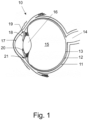
- Figure 1 depicts a cross section of a human eye 10.
- the eye 10 is a sense organ capable of vision having an almost spherical configuration. Seen in the direction of light impinging on the eye, the anterior or frontal side of the eye 10 is formed by the cornea 17 having a stronger curvature compared to the posterior side, being the sclera 11, from which the optic nerve 14 leaves the eye 10 at its posterior side towards the brain.
- the limbus connects the cornea 17 and the sclera 11.
- the cornea 17, the iris 20 and the lens capsule 16 form the anterior chamber 18 filled with aqueous humor liquid. Behind the lens 16 the vitreous body 15 is filled with vitreous gel.
- the lens 16 is suspended in the eye by means of the ciliary body 21 composed of ciliary muscle and fibers.
- Reference numeral 19 denotes the posterior chamber present between the lens 16, the ciliary body 21 and the iris 20.
- the fundus or area opposite to the lens 16 at the posterior side of the eye 10 includes the macula 13, as well as the retina, being the innermost tissue layer containing the rod and cone vision cells.
- Reference numeral 12 denotes the choroid.
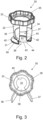
- FIG. 2 shows a first embodiment of a support element 30 suitable for intraocular administration of a substance into the human or animal eye.
- the support element 30 comprises an elliptical annular shaped base structure 31. From the base structure 31 a longitudinal, cylindrical, open hollow body 35 extends, having an upright circumferential wall 32 that extends over a distance transverse to the base structure 31.
- the upright circumferential wall 32 of the open hollow body 35 ends in a gear shaped grip 33, forming an ergonomic grip for firmly gripping and manipulating, i.e. positioning of the support element at the eye 10 by hand.
- the hollow body 35 may have a form or shape that slightly tapers outwardly near the end comprising the grip 33, this to provide a sufficiently large gripping area. Those skilled in the art will appreciate that other types of ergonomic grips may be provided.
- the annular shaped configuration of the elliptical base structure 31 provides a support surface serving as a circumferential support flange of the support element 30 for placement on the eye.
- the outer or external face of the support flange 31 forms an obtuse angle with the outer or external face of the upright wall 32 of the hollow body 35.
- the upright circumferential wall 32 comprises an open access section 34, i.e. open to the interior of the hollow body 35, extending from the base structure 31 in longitudinal direction of the hollow body 35.
- the access section 34 defines an open area having a width and height sufficiently for administration of a substance from the access section 34 into the eye, while providing visual inspection of the administration of the substance by a doctor, a physician or a veterinarian when applying same to the eye.
- the access section has a height of about half the length of the circumferential wall 32 and a width or arc length of about one sixth of the circumference of the wall 32.
- an elliptical, circular or otherwise shaped access opening may be provided.
- part 38 of the annular base structure or flange 31 connecting to the access section 34 is cut away, i.e. interrupted or open and connects to the open access section 34.
- a wing shaped spreading element 36, 37 extends over a distance in radial direction from the base structure 31 and extends from the base structure 31 in longitudinal direction of the upright circumferential wall 32 of the hollow body 35.
- the wing shaped spreading elements 36, 37 are at least spaced apart over the circumferential width or arc length of the access section 34.
- the wing shaped spreading elements 36, 37 flair outwardly from the circumferential wall 32 and have a curved shape bending towards each other.
- the wing shaped elements 36, 37 are tapered towards the base structure 31, that is the distance over which the wing shaped elements 36, 37 extend in radial direction from the circumferential wall 32 reduces in the direction of the base structure 31. Thereby avoiding as much as possible tissue contact with the eye and its surrounding area, hence reducing irritation and trauma to the eye and tissue.
- the radial length of the wing shaped elements 36, 37 near the base structure 31 ends at an outer annular edge 39 of the base structure 31.
- the wing shaped elements 36, 37 have a longitudinal length exceeding the length of the open access section 34. However, it may be sufficient for the wing shaped elements 36, 37 to just cover the length of the access section 34 in longitudinal direction of the wall 32. This to effectively protect the open access section 34 against the entrance of contaminations while administering a substance.
- the annular opening 41 of the base structure 31 has a size such that the inner annular edge 40 of the base structure 31 corresponds to, i.e. coincides with the corneal limbus of the eye 10 when the support element is positioned at or into the eye.
- the inner annular edge 40 is partly shown by a dashed line.
- each of the wing shaped elements 36, 37 at the inner sides thereof facing each other is provided with markers 42, marking an administration position.
- markers 42 marking an administration position.
- the wing shaped elements 36, 37 may be made of a plastic material, for example, such that a doctor or physician may indicate himself or herself a suitable marking at a wing surface, such as by scratching or printing a mark, after measuring the human eye. In this way, a very versatile support element is provided, capable of supporting nearly all types of administration needles or syringes or the like.
- two markers 42 are provided on each wing shaped element, marking administration positions at a distance 43 of 3.5 mm and a distance 44 of 4 mm from the corneal limbus of the eye 10, i.e. measured in radial direction form the inner annular edge 40 of the base structure 31, respectively.
- Figure 2 shows, for clarity purposes, a top view of the support element 30 of Figure 1 .
- Figure 4 shows a second embodiment of a support element 50 according to the present invention
- Figure 5 shows a cross section along the line of intersection V-V in Figure 4 .
- the positioning means of the intraocular administration device comprise a positioning element formed as an extension or connecting element 51 disposed at the interrupted part 38 of the elliptical shaped base structure 31 (see Figure 2 ).
- the extension or connecting element 51 extends between and connects the two wing shaped elements 36, 37 and has an inner annular edge 52 defining a distance of 3.5 mm from the corneal limbus of the eye, i.e. a distance of 3.5 mm with respect to the inner annular edge 40 of the base structure 31 measured in outer radial direction.
- the extension or connecting element 51 further comprises a rectangular recess 53 open from the inner annular edge 52 and extending in radial direction of the base structure 31.
- the closed edge 54 of the recess 53 defines a distance of 4 mm from the corneal limbus of the eye, i.e. a distance of 4 mm from the inner annular edge 40 of the base structure 31, measured in outer radial direction.
- the extension or connecting element 51 may have an inner annular edge 52 placed closer to or further away from the inner annular edge 40 of the base structure 31.
- the extension or connecting element 51 may also have a stepped shaped inner annular edge 52, defining a plurality of administration positions, and/or several recesses 53 extending at different radial distances, for example (not shown).
- the recess may have any shape, in a particular embodiment however, the recess 53 is arranged for accommodating hypodermic needles of 27, 30, 31 and 33 gauge, i.e. 0.361 mm, 0.25 mm, 0.226 mm and 0.18 mm, respectively.
- Figure 10 shows an alternative embodiment incorporating an opening 530 present in the extension or connecting element 51.
- the opening 530 is depicted as having an elongated shape, for example as a rectangular opening with rounded corners or as an ellipse 530.
- its major axis extends in radial direction of the base structure 31.
- the elongated shaped opening 530 (here an ellipse) allows the insertion of the needle are several different radial distances from the corneal limbus of the eye, (i.e. at 3.5 mm or 4.0 mm).
- the opening can also be a circular opening.
- FIG. 6 shows a third embodiment of a support element 60 in accordance with the present invention.
- the support element 60 comprises an extension or connecting element 51 that extends between and connects the two wing shaped elements 36, 37 and has an inner annular edge 52 defining a distance of 3.5 mm from the corneal limbus of the eye, i.e. a distance of 3.5 mm with respect to the inner annular edge 40 of the base structure 31 measured in outer radial direction, like the support element 50.
- the extension or connecting element 51 of the support element 60 comprises a V-shaped recess 61 open from the inner annular edge 52 and extending in radial direction of the base structure 31.
- the valley or intersection point 62 of the recess 61 defines a distance of 4 mm from the corneal limbus of the eye, i.e. a distance of 4 mm from the inner annular edge 40 of the base structure 31, measured in outer radial direction.
- the valley or intersection point 62 of the recess 61 serves as an orientation projection or point to be oriented against the edge of the limbus of the eye.
- Such orientation projection may also be designed as a lip shaped element 71 extending radially inwardly of the hollow body 35, i.e. inwardly from the base structure 31, i.e. the inner annular edge 40, for example, as shown in a fourth embodiment of the support element 70 according to the present invention, illustrated in Figure 7 .
- Figure 8 shows the embodiments 30, 50, 60, 70 of the present invention in a front face, against the wing shaped element 36.
- a hypodermic needle or syringe is illustrated, having an insertion end 81 for administering a substance, i.e. a liquid, into the eye 10.
- the distance r illustrates the administering distance from the limbus of eye when a support device 30, 50, 60, 70 is placed on the eye 10. Such as a distance of 3.5 mm or 4 mm, for example.
- the distance d illustrates an injection distance from the lower surface 82 of the base structure 31, such as a distance of 4 - 6 mm, for example.
- Figure 9 illustrates a top view of a fifth embodiment of a support element 90 according to the present invention, wherein the base structure 31 exhibits an intermittent elliptical configuration being formed of four tangentially spaced apart base structure parts 31a, 31b, 31c, 31d. Because of the interrupted, intermittent elliptical configuration of the base structure 31 the contact area with the eye 10 is minimal, so that the patient is optimally protected against trauma and/or irritation.
- open access spaces 90a, 90b, 90c between the base structure parts 31a, 31b, 31c, 31d allows for a better visual overview of the region of the eye 10 as the support element no longer obscures for the greater part the region of interest of the eye 10.
- the base structure parts 31a, 31b, 31c, 31d may have different arc lengths.
- the open access spaces 90a, 90b, 90c may have different sizes.
- the base structure parts 31a, 31b, 31c, 31d and/or the open access spaces 90a, 90b, 90c may have identical arc lengths, for example.
- the base structure may be at least comprised of three separated base structure parts.
- the base structure 31 as well as the base structure parts 31a, 31b, 31c, 31d may comprise a circular shaped configuration.
- the support element of the intraocular administration device according to the present invention may be manufactured from a plastics material, in particular a plastics material suitable for therapeutical and medical purposes, and may be designed as a disposable device.
- the support element according to the present invention is suitable for safely and securely administering a substance, such as a medical liquid, into the human or animal eye by a large variety of hypodermic needles, syringes and the like, having different dimensions and designs.
Landscapes
- Health & Medical Sciences (AREA)
- Vascular Medicine (AREA)
- General Health & Medical Sciences (AREA)
- Public Health (AREA)
- Heart & Thoracic Surgery (AREA)
- Engineering & Computer Science (AREA)
- Life Sciences & Earth Sciences (AREA)
- Animal Behavior & Ethology (AREA)
- Veterinary Medicine (AREA)
- Biomedical Technology (AREA)
- Ophthalmology & Optometry (AREA)
- Dermatology (AREA)
- Anesthesiology (AREA)
- Hematology (AREA)
- Prostheses (AREA)
- Infusion, Injection, And Reservoir Apparatuses (AREA)
Claims (15)
- Vorrichtung zur intraokularen Verabreichung zur intraokularen Verabreichung einer Substanz, zum Beispiel eines Medikaments, in ein menschliches oder tierisches Auge (10) mithilfe einer hypodermischen Nadel, wobei die Vorrichtung umfasst:
ein Stützelement (30; 50; 60; 70; 90), das dazu angeordnet ist, an dem Auge (10) platziert zu werden, wobei das Stützelement umfasst:eine Basisstruktur (31) mit einer elliptisch geformten Auslegung zur Platzierung an dem Auge (10); undPositionierungsmittel zur Unterstützung der Verabreichung der Substanz in mindestens einem vorbestimmten Abstand zum Hornhautlimbus des Auges, wobei das Stützelement ferner umfasst:einen Hohlkörper (35), der eine aufrechte Umfangswand (32) definiert, die sich in Querrichtung von der Basisstruktur (31) erstreckt, wobei die aufrechte Wand (32) einen offenen Zugangsbereich (34) umfasst, der sich von der Basisstruktur (31) erstreckt und zur Verabreichung der Substanz und zur Sichtkontrolle der Verabreichung der Substanz geeignet ist,dadurch gekennzeichnet, dass der Hohlkörper (35) ferner Spreizelemente (36, 37) zum Spreizen der Augenlider des Auges (10) umfasst, wobei die Spreizelemente (36, 37) zwei beabstandete Flügelelemente umfasst, die sich in radialer Richtung von der Basisstruktur (31) in Längsrichtung des Hohlkörpers auf beiden Seiten des offenen Zugangsbereichs (34) erstrecken. - Vorrichtung zur intraokularen Verabreichung nach Anspruch 1, wobei die Basisstruktur (31) eine unterbrochene elliptische Form umfasst, die eine Öffnung (38) in der Basisstruktur definiert, die mit dem offenen Zugangsbereich (34) verbunden ist, und wobei die Positionierungsmittel mindestens eine mindestens eine Verabreichungsposition definierende Markierung (42) umfassen, insbesondere eine erste und eine zweite Markierung in einem Abstand von 3,5 mm bzw. 4 mm zu dem Hornhautlimbus des Auges (10).
- Vorrichtung zur intraokularen Verabreichung nach Anspruch 1, wobei die Basisstruktur (31) eine längliche Öffnung (530) oder eine elliptische Öffnung (530) oder eine kreisförmige Öffnung (530) in der Basisstruktur umfasst, und die Positionierungsmittel mindestens eine mindestens eine Verabreichungsposition definierende Markierung (42) umfassen, insbesondere eine erste und eine zweite Markierung in einem Abstand von 3,5 mm bzw. 4 mm zu dem Hornhautlimbus des Auges (10).
- Vorrichtung zur intraokularen Verabreichung nach Anspruch 1, wobei die Positionierungsmittel ein Positionierungselement umfassen, das als eine Ausdehnung (51) definiert ist, die an einem unterbrochenen Teil der elliptisch geformten Basisstruktur (31) angeordnet ist, wobei das Positionierungselement mindestens eine Verabreichungsposition (52, 53) definiert, wobei insbesondere das Positionierungselement eine erste (52) und eine zweite (53) Verabreichungsposition im Abstand von 3,5 mm bzw. 4 mm zu dem Hornhautlimbus des Auges (10) definiert.
- Vorrichtung zur intraokularen Verabreichung nach Anspruch 4, wobei das Positionierungselement (51) eine ringförmig geformte Auslegung hat und eine ringförmige Innenkante (52) umfasst, die einen Abstand von 3,5 mm zu dem Hornhautlimbus des Auges definiert, und eine Aussparung (53), die sich in radialer Richtung von der Basisstruktur erstreckt und einen Abstand von 4 mm zu dem Hornhautlimbus des Auges definiert.
- Vorrichtung zur intraokularen Verabreichung nach Anspruch 5, wobei die Aussparung (53) zur Aufnahme von hypodermischen Nadeln mit einer Gauge-Zahl von 27, 30, 31 und 33 angeordnet ist.
- Vorrichtung zur intraokularen Verabreichung nach einem der vorhergehenden Ansprüche, wobei die flügelförmigen Elemente (36, 37) in Richtung der Basisstruktur (31) konisch zulaufen.
- Vorrichtung zur intraokularen Verabreichung nach einem der vorhergehenden Ansprüche, wobei eine radiale Länge der flügelförmigen Elemente (36, 37) nahe der Basisstruktur (31) an einer ringförmigen Außenkante (39) der Basisstruktur endet.
- Vorrichtung zur intraokularen Verabreichung nach einem der vorhergehenden Ansprüche, wobei eine Längslänge der flügelförmigen Elemente (36, 37) einer Längslänge des offenen Zugangsbereiches (34) der Umfangswand (32) entspricht.
- Vorrichtung zur intraokularen Verabreichung nach einem der Ansprüche 1 - 8, wobei eine Längslänge der flügelförmigen Elemente (36, 37) einer Längslänge des offenen Zugangsbereiches (34) der Umfangswand (32) entspricht.
- Vorrichtung zur intraokularen Verabreichung nach einem der vorhergehenden Ansprüche, wobei die elliptische Basisstruktur (31) eine kreisförmig geformte Auslegung oder eine ringförmig geformte Auslegung hat.
- Vorrichtung zur intraokularen Verabreichung nach Anspruch 11, wobei eine ringförmige Innenkante (40) der Basisstruktur (31) dem Hornhautlimbus des Auges (10) entspricht.
- Vorrichtung zur intraokularen Verabreichung nach einem der vorhergehenden Ansprüche, wobei die Basisstruktur (31) aus mindestens drei intermittierenden elliptisch ausgerichteten Stützelementteilen (31a, 31b, 31c) gebildet ist.
- Vorrichtung zur intraokularen Verabreichung nach Anspruch 12, wobei die elliptisch ausgerichteten Stützelementteile (31a, 31b, 31c) an Positionen mit gleichem Abstand dazwischen entlang der elliptischen Auslegung der Basisstruktur (31) positioniert sind.
- Vorrichtung zur intraokularen Verabreichung nach einem der vorhergehenden Ansprüche, wobei das Stützelement mit mindestens einem Ausrichtungsvorsprung (71) versehen ist, um gegen einen Rand des Limbus des Auges (10) ausgerichtet zu werden.
Applications Claiming Priority (1)
| Application Number | Priority Date | Filing Date | Title |
|---|---|---|---|
| NL2023576A NL2023576B1 (en) | 2019-07-26 | 2019-07-26 | An intraocular administration device for intraocular administration of a substance, for example a medication, into a human or animal eye. |
Publications (2)
| Publication Number | Publication Date |
|---|---|
| EP3769729A1 EP3769729A1 (de) | 2021-01-27 |
| EP3769729B1 true EP3769729B1 (de) | 2024-08-21 |
Family
ID=68426270
Family Applications (1)
| Application Number | Title | Priority Date | Filing Date |
|---|---|---|---|
| EP19206855.9A Active EP3769729B1 (de) | 2019-07-26 | 2019-11-04 | Vorrichtung zur intraokularen verabreichung zur intraokularen verabreichung einer substanz, zum beispiel eines medikaments, in ein menschliches oder tierisches auge |
Country Status (5)
| Country | Link |
|---|---|
| EP (1) | EP3769729B1 (de) |
| JP (1) | JP2021020051A (de) |
| ES (1) | ES2986132T3 (de) |
| FI (1) | FI3769729T3 (de) |
| NL (1) | NL2023576B1 (de) |
Family Cites Families (2)
| Publication number | Priority date | Publication date | Assignee | Title |
|---|---|---|---|---|
| NL1033357C2 (nl) | 2007-02-08 | 2008-08-11 | Arnaldo Goncalves | Inrichting voor het met behulp van een injectie-naald intraoculair toedienen van een substantie, bijvoorbeeld een medicament, in een menselijk of dierlijk oog. |
| US11071643B2 (en) * | 2014-11-28 | 2021-07-27 | Visionisti Oy | Ocular therapeutics tool |
-
2019
- 2019-07-26 NL NL2023576A patent/NL2023576B1/en active
- 2019-11-04 ES ES19206855T patent/ES2986132T3/es active Active
- 2019-11-04 FI FIEP19206855.9T patent/FI3769729T3/fi active
- 2019-11-04 EP EP19206855.9A patent/EP3769729B1/de active Active
-
2020
- 2020-04-27 JP JP2020078208A patent/JP2021020051A/ja active Pending
Also Published As
| Publication number | Publication date |
|---|---|
| FI3769729T3 (fi) | 2024-09-03 |
| NL2023576B1 (en) | 2021-02-18 |
| JP2021020051A (ja) | 2021-02-18 |
| ES2986132T3 (es) | 2024-11-08 |
| EP3769729A1 (de) | 2021-01-27 |
Similar Documents
| Publication | Publication Date | Title |
|---|---|---|
| ES2677879T3 (es) | Sistema de administración para implante ocular | |
| US9144516B2 (en) | Device for intraocular administration of a substance, for example a medication, into a human or animal eye by means of a hypodermic needle | |
| KR100732262B1 (ko) | 약물 전달 장치 | |
| US7402156B2 (en) | Counter pressure device for ophthalmic drug delivery | |
| EP2109425B1 (de) | Vorrichtung zur intraokulären verabreichung einer substanz, beispielsweise eines medikaments, in ein menschliches oder tierisches auge mit einer kanüle | |
| EP2696822B1 (de) | Vorrichtung zur intraokularen injektion | |
| US20080243095A1 (en) | Method and Apparatus for Ophthalmic Medication Delivery and Ocular Wound Recovery | |
| US10667944B2 (en) | Ophthalmic intra ocular access tool | |
| US11051797B2 (en) | Eyelid speculum | |
| WO2011077115A1 (en) | Ocular device for guiding a needle | |
| EP3769729B1 (de) | Vorrichtung zur intraokularen verabreichung zur intraokularen verabreichung einer substanz, zum beispiel eines medikaments, in ein menschliches oder tierisches auge | |
| EP3682856B1 (de) | Vorrichtung geeignet zur intraokularen verabreichung einer substanz, zum beispiel eines medikaments, in ein menschliches oder tierisches auge | |
| EP3785684B1 (de) | Vorrichtung zur unterstützung von okularen injektionen | |
| JP2568006Y2 (ja) | 眼科用注入針 | |
| IL293586A (en) | Eye syringe and method |
Legal Events
| Date | Code | Title | Description |
|---|---|---|---|
| PUAI | Public reference made under article 153(3) epc to a published international application that has entered the european phase |
Free format text: ORIGINAL CODE: 0009012 |
|
| STAA | Information on the status of an ep patent application or granted ep patent |
Free format text: STATUS: THE APPLICATION HAS BEEN PUBLISHED |
|
| AK | Designated contracting states |
Kind code of ref document: A1 Designated state(s): AL AT BE BG CH CY CZ DE DK EE ES FI FR GB GR HR HU IE IS IT LI LT LU LV MC MK MT NL NO PL PT RO RS SE SI SK SM TR |
|
| AX | Request for extension of the european patent |
Extension state: BA ME |
|
| STAA | Information on the status of an ep patent application or granted ep patent |
Free format text: STATUS: REQUEST FOR EXAMINATION WAS MADE |
|
| 17P | Request for examination filed |
Effective date: 20210705 |
|
| RBV | Designated contracting states (corrected) |
Designated state(s): AL AT BE BG CH CY CZ DE DK EE ES FI FR GB GR HR HU IE IS IT LI LT LU LV MC MK MT NL NO PL PT RO RS SE SI SK SM TR |
|
| P01 | Opt-out of the competence of the unified patent court (upc) registered |
Effective date: 20230527 |
|
| GRAP | Despatch of communication of intention to grant a patent |
Free format text: ORIGINAL CODE: EPIDOSNIGR1 |
|
| STAA | Information on the status of an ep patent application or granted ep patent |
Free format text: STATUS: GRANT OF PATENT IS INTENDED |
|
| INTG | Intention to grant announced |
Effective date: 20240319 |
|
| GRAS | Grant fee paid |
Free format text: ORIGINAL CODE: EPIDOSNIGR3 |
|
| GRAA | (expected) grant |
Free format text: ORIGINAL CODE: 0009210 |
|
| STAA | Information on the status of an ep patent application or granted ep patent |
Free format text: STATUS: THE PATENT HAS BEEN GRANTED |
|
| AK | Designated contracting states |
Kind code of ref document: B1 Designated state(s): AL AT BE BG CH CY CZ DE DK EE ES FI FR GB GR HR HU IE IS IT LI LT LU LV MC MK MT NL NO PL PT RO RS SE SI SK SM TR |
|
| REG | Reference to a national code |
Ref country code: GB Ref legal event code: FG4D |
|
| REG | Reference to a national code |
Ref country code: CH Ref legal event code: EP |
|
| REG | Reference to a national code |
Ref country code: FI Ref legal event code: FGE |
|
| REG | Reference to a national code |
Ref country code: DE Ref legal event code: R096 Ref document number: 602019057307 Country of ref document: DE |
|
| REG | Reference to a national code |
Ref country code: IE Ref legal event code: FG4D |
|
| REG | Reference to a national code |
Ref country code: SE Ref legal event code: TRGR |
|
| REG | Reference to a national code |
Ref country code: ES Ref legal event code: FG2A Ref document number: 2986132 Country of ref document: ES Kind code of ref document: T3 Effective date: 20241108 |
|
| REG | Reference to a national code |
Ref country code: LT Ref legal event code: MG9D |
|
| REG | Reference to a national code |
Ref country code: NL Ref legal event code: MP Effective date: 20240821 |
|
| REG | Reference to a national code |
Ref country code: AT Ref legal event code: MK05 Ref document number: 1714792 Country of ref document: AT Kind code of ref document: T Effective date: 20240821 |
|
| PG25 | Lapsed in a contracting state [announced via postgrant information from national office to epo] |
Ref country code: NL Free format text: LAPSE BECAUSE OF FAILURE TO SUBMIT A TRANSLATION OF THE DESCRIPTION OR TO PAY THE FEE WITHIN THE PRESCRIBED TIME-LIMIT Effective date: 20240821 Ref country code: GR Free format text: LAPSE BECAUSE OF FAILURE TO SUBMIT A TRANSLATION OF THE DESCRIPTION OR TO PAY THE FEE WITHIN THE PRESCRIBED TIME-LIMIT Effective date: 20241122 Ref country code: PL Free format text: LAPSE BECAUSE OF FAILURE TO SUBMIT A TRANSLATION OF THE DESCRIPTION OR TO PAY THE FEE WITHIN THE PRESCRIBED TIME-LIMIT Effective date: 20240821 Ref country code: PT Free format text: LAPSE BECAUSE OF FAILURE TO SUBMIT A TRANSLATION OF THE DESCRIPTION OR TO PAY THE FEE WITHIN THE PRESCRIBED TIME-LIMIT Effective date: 20241223 |
|
| PG25 | Lapsed in a contracting state [announced via postgrant information from national office to epo] |
Ref country code: BG Free format text: LAPSE BECAUSE OF FAILURE TO SUBMIT A TRANSLATION OF THE DESCRIPTION OR TO PAY THE FEE WITHIN THE PRESCRIBED TIME-LIMIT Effective date: 20240821 |
|
| PG25 | Lapsed in a contracting state [announced via postgrant information from national office to epo] |
Ref country code: LV Free format text: LAPSE BECAUSE OF FAILURE TO SUBMIT A TRANSLATION OF THE DESCRIPTION OR TO PAY THE FEE WITHIN THE PRESCRIBED TIME-LIMIT Effective date: 20240821 |
|
| PG25 | Lapsed in a contracting state [announced via postgrant information from national office to epo] |
Ref country code: IS Free format text: LAPSE BECAUSE OF FAILURE TO SUBMIT A TRANSLATION OF THE DESCRIPTION OR TO PAY THE FEE WITHIN THE PRESCRIBED TIME-LIMIT Effective date: 20241221 Ref country code: AT Free format text: LAPSE BECAUSE OF FAILURE TO SUBMIT A TRANSLATION OF THE DESCRIPTION OR TO PAY THE FEE WITHIN THE PRESCRIBED TIME-LIMIT Effective date: 20240821 |
|
| PG25 | Lapsed in a contracting state [announced via postgrant information from national office to epo] |
Ref country code: HR Free format text: LAPSE BECAUSE OF FAILURE TO SUBMIT A TRANSLATION OF THE DESCRIPTION OR TO PAY THE FEE WITHIN THE PRESCRIBED TIME-LIMIT Effective date: 20240821 |
|
| PG25 | Lapsed in a contracting state [announced via postgrant information from national office to epo] |
Ref country code: RS Free format text: LAPSE BECAUSE OF FAILURE TO SUBMIT A TRANSLATION OF THE DESCRIPTION OR TO PAY THE FEE WITHIN THE PRESCRIBED TIME-LIMIT Effective date: 20241121 |
|
| PG25 | Lapsed in a contracting state [announced via postgrant information from national office to epo] |
Ref country code: RS Free format text: LAPSE BECAUSE OF FAILURE TO SUBMIT A TRANSLATION OF THE DESCRIPTION OR TO PAY THE FEE WITHIN THE PRESCRIBED TIME-LIMIT Effective date: 20241121 Ref country code: PT Free format text: LAPSE BECAUSE OF FAILURE TO SUBMIT A TRANSLATION OF THE DESCRIPTION OR TO PAY THE FEE WITHIN THE PRESCRIBED TIME-LIMIT Effective date: 20241223 Ref country code: PL Free format text: LAPSE BECAUSE OF FAILURE TO SUBMIT A TRANSLATION OF THE DESCRIPTION OR TO PAY THE FEE WITHIN THE PRESCRIBED TIME-LIMIT Effective date: 20240821 Ref country code: NL Free format text: LAPSE BECAUSE OF FAILURE TO SUBMIT A TRANSLATION OF THE DESCRIPTION OR TO PAY THE FEE WITHIN THE PRESCRIBED TIME-LIMIT Effective date: 20240821 Ref country code: LV Free format text: LAPSE BECAUSE OF FAILURE TO SUBMIT A TRANSLATION OF THE DESCRIPTION OR TO PAY THE FEE WITHIN THE PRESCRIBED TIME-LIMIT Effective date: 20240821 Ref country code: IS Free format text: LAPSE BECAUSE OF FAILURE TO SUBMIT A TRANSLATION OF THE DESCRIPTION OR TO PAY THE FEE WITHIN THE PRESCRIBED TIME-LIMIT Effective date: 20241221 Ref country code: HR Free format text: LAPSE BECAUSE OF FAILURE TO SUBMIT A TRANSLATION OF THE DESCRIPTION OR TO PAY THE FEE WITHIN THE PRESCRIBED TIME-LIMIT Effective date: 20240821 Ref country code: GR Free format text: LAPSE BECAUSE OF FAILURE TO SUBMIT A TRANSLATION OF THE DESCRIPTION OR TO PAY THE FEE WITHIN THE PRESCRIBED TIME-LIMIT Effective date: 20241122 Ref country code: BG Free format text: LAPSE BECAUSE OF FAILURE TO SUBMIT A TRANSLATION OF THE DESCRIPTION OR TO PAY THE FEE WITHIN THE PRESCRIBED TIME-LIMIT Effective date: 20240821 Ref country code: AT Free format text: LAPSE BECAUSE OF FAILURE TO SUBMIT A TRANSLATION OF THE DESCRIPTION OR TO PAY THE FEE WITHIN THE PRESCRIBED TIME-LIMIT Effective date: 20240821 |
|
| PG25 | Lapsed in a contracting state [announced via postgrant information from national office to epo] |
Ref country code: SM Free format text: LAPSE BECAUSE OF FAILURE TO SUBMIT A TRANSLATION OF THE DESCRIPTION OR TO PAY THE FEE WITHIN THE PRESCRIBED TIME-LIMIT Effective date: 20240821 Ref country code: RO Free format text: LAPSE BECAUSE OF FAILURE TO SUBMIT A TRANSLATION OF THE DESCRIPTION OR TO PAY THE FEE WITHIN THE PRESCRIBED TIME-LIMIT Effective date: 20240821 Ref country code: DK Free format text: LAPSE BECAUSE OF FAILURE TO SUBMIT A TRANSLATION OF THE DESCRIPTION OR TO PAY THE FEE WITHIN THE PRESCRIBED TIME-LIMIT Effective date: 20240821 |
|
| PG25 | Lapsed in a contracting state [announced via postgrant information from national office to epo] |
Ref country code: EE Free format text: LAPSE BECAUSE OF FAILURE TO SUBMIT A TRANSLATION OF THE DESCRIPTION OR TO PAY THE FEE WITHIN THE PRESCRIBED TIME-LIMIT Effective date: 20240821 |
|
| PG25 | Lapsed in a contracting state [announced via postgrant information from national office to epo] |
Ref country code: CZ Free format text: LAPSE BECAUSE OF FAILURE TO SUBMIT A TRANSLATION OF THE DESCRIPTION OR TO PAY THE FEE WITHIN THE PRESCRIBED TIME-LIMIT Effective date: 20240821 |
|
| PG25 | Lapsed in a contracting state [announced via postgrant information from national office to epo] |
Ref country code: SK Free format text: LAPSE BECAUSE OF FAILURE TO SUBMIT A TRANSLATION OF THE DESCRIPTION OR TO PAY THE FEE WITHIN THE PRESCRIBED TIME-LIMIT Effective date: 20240821 |
|
| REG | Reference to a national code |
Ref country code: DE Ref legal event code: R097 Ref document number: 602019057307 Country of ref document: DE |
|
| PLBE | No opposition filed within time limit |
Free format text: ORIGINAL CODE: 0009261 |
|
| STAA | Information on the status of an ep patent application or granted ep patent |
Free format text: STATUS: NO OPPOSITION FILED WITHIN TIME LIMIT |
|
| PG25 | Lapsed in a contracting state [announced via postgrant information from national office to epo] |
Ref country code: MC Free format text: LAPSE BECAUSE OF FAILURE TO SUBMIT A TRANSLATION OF THE DESCRIPTION OR TO PAY THE FEE WITHIN THE PRESCRIBED TIME-LIMIT Effective date: 20240821 |
|
| PG25 | Lapsed in a contracting state [announced via postgrant information from national office to epo] |
Ref country code: LU Free format text: LAPSE BECAUSE OF NON-PAYMENT OF DUE FEES Effective date: 20241104 |
|
| 26N | No opposition filed |
Effective date: 20250522 |
|
| REG | Reference to a national code |
Ref country code: BE Ref legal event code: MM Effective date: 20241130 |
|
| PG25 | Lapsed in a contracting state [announced via postgrant information from national office to epo] |
Ref country code: BE Free format text: LAPSE BECAUSE OF NON-PAYMENT OF DUE FEES Effective date: 20241130 |
|
| PG25 | Lapsed in a contracting state [announced via postgrant information from national office to epo] |
Ref country code: IE Free format text: LAPSE BECAUSE OF NON-PAYMENT OF DUE FEES Effective date: 20241104 |
|
| REG | Reference to a national code |
Ref country code: CH Ref legal event code: U11 Free format text: ST27 STATUS EVENT CODE: U-0-0-U10-U11 (AS PROVIDED BY THE NATIONAL OFFICE) Effective date: 20251201 |
|
| PGFP | Annual fee paid to national office [announced via postgrant information from national office to epo] |
Ref country code: DE Payment date: 20251119 Year of fee payment: 7 |
|
| PGFP | Annual fee paid to national office [announced via postgrant information from national office to epo] |
Ref country code: GB Payment date: 20251121 Year of fee payment: 7 |
|
| PGFP | Annual fee paid to national office [announced via postgrant information from national office to epo] |
Ref country code: NO Payment date: 20251125 Year of fee payment: 7 |
|
| PGFP | Annual fee paid to national office [announced via postgrant information from national office to epo] |
Ref country code: IT Payment date: 20251125 Year of fee payment: 7 Ref country code: FI Payment date: 20251125 Year of fee payment: 7 |
|
| PGFP | Annual fee paid to national office [announced via postgrant information from national office to epo] |
Ref country code: FR Payment date: 20251126 Year of fee payment: 7 |
|
| PGFP | Annual fee paid to national office [announced via postgrant information from national office to epo] |
Ref country code: CH Payment date: 20251201 Year of fee payment: 7 Ref country code: SE Payment date: 20251119 Year of fee payment: 7 |
|
| PGFP | Annual fee paid to national office [announced via postgrant information from national office to epo] |
Ref country code: ES Payment date: 20251229 Year of fee payment: 7 |
|
| PG25 | Lapsed in a contracting state [announced via postgrant information from national office to epo] |
Ref country code: HU Free format text: LAPSE BECAUSE OF FAILURE TO SUBMIT A TRANSLATION OF THE DESCRIPTION OR TO PAY THE FEE WITHIN THE PRESCRIBED TIME-LIMIT; INVALID AB INITIO Effective date: 20191104 |