EP3769714B1 - Zahnimplantatführungswerkzeugsatz - Google Patents
Zahnimplantatführungswerkzeugsatz Download PDFInfo
- Publication number
- EP3769714B1 EP3769714B1 EP20186077.2A EP20186077A EP3769714B1 EP 3769714 B1 EP3769714 B1 EP 3769714B1 EP 20186077 A EP20186077 A EP 20186077A EP 3769714 B1 EP3769714 B1 EP 3769714B1
- Authority
- EP
- European Patent Office
- Prior art keywords
- dental implant
- drill bit
- guiding
- handpiece
- hole
- Prior art date
- Legal status (The legal status is an assumption and is not a legal conclusion. Google has not performed a legal analysis and makes no representation as to the accuracy of the status listed.)
- Active
Links
Images





Classifications
-
- A—HUMAN NECESSITIES
- A61—MEDICAL OR VETERINARY SCIENCE; HYGIENE
- A61C—DENTISTRY; APPARATUS OR METHODS FOR ORAL OR DENTAL HYGIENE
- A61C1/00—Dental machines for boring or cutting ; General features of dental machines or apparatus, e.g. hand-piece design
- A61C1/08—Machine parts specially adapted for dentistry
- A61C1/082—Positioning or guiding, e.g. of drills
- A61C1/084—Positioning or guiding, e.g. of drills of implanting tools
-
- A—HUMAN NECESSITIES
- A61—MEDICAL OR VETERINARY SCIENCE; HYGIENE
- A61C—DENTISTRY; APPARATUS OR METHODS FOR ORAL OR DENTAL HYGIENE
- A61C1/00—Dental machines for boring or cutting ; General features of dental machines or apparatus, e.g. hand-piece design
- A61C1/08—Machine parts specially adapted for dentistry
- A61C1/082—Positioning or guiding, e.g. of drills
-
- A—HUMAN NECESSITIES
- A61—MEDICAL OR VETERINARY SCIENCE; HYGIENE
- A61C—DENTISTRY; APPARATUS OR METHODS FOR ORAL OR DENTAL HYGIENE
- A61C8/00—Means to be fixed to the jaw-bone for consolidating natural teeth or for fixing dental prostheses thereon; Dental implants; Implanting tools
- A61C8/0089—Implanting tools or instruments
Definitions
- the present invention relates to an apparatus for a dentist, and more particularly to a tool set for dental implant and an assembly thereof.
- a dental implant operation is a tooth replacement technique for implanting an implant into alveolar bone, and then installing an artificial tooth to fix missing tooth.
- One of the key devices affecting the effect of dental implant is a handpiece, which is also called a dental handpiece.
- document WO 2010/025191 A1 discloses a conventional dental drill guide system, including a handpiece guide and a custom surgical guide, wherein the custom surgical guide may be designed based on patient-specific data and fits conformingly over at least a portion of the patient's dentition at the implant site, wherein the handpiece guide is attachable to an existing dental handpiece.
- Document JP H01 166755 A shows an implant implantation groove forming device for dental surgery, which is an auxiliary tool for use with a dental handpiece and being configured for laterally guiding a cutting operation.
- the auxiliary tool includes an insertion port for insertion and guidance of a headpiece head portion.
- the bottom of the insertion port defines a semi-opened guideway, wherein the headpiece head may be laterally pulled through a space above the opening.
- Document US 3 088 745 A further teaches a plastic bur sleeve for dental handpieces, wherein the plastic sleeve sleeves a shank of the bur, when mounted inside a handpiece head for absorbing vibration from the drilling.
- a fixture is provided which is installed on the head and is adapted to guide the shank of the bur into the central hole.
- FIG. 1 is a schematic view of a conventional dental implant device.
- a dentist Before implant installation, a dentist must first drill, or ream and grind a hole on alveolar bone 100, to facilitate subsequent implant operations.
- a user installs an appropriate drill bit 102 on the handpiece 101 first, and then holds the handpiece 101 to directly drill the alveolar bone 100 at a drilling place.
- An operational position of the dental implant process is in a mouth of the human body and there are other teeth 103 on both sides of the drilling place, the operating space is quite limited, and the drill bit 102 of the handpiece 101 is also rotating fast during operation, so it is easy to occur undesired conditions in the drilling process, for example, the drill bit 102 drills at an inaccurate position, or the drill bit 102 skews or shakes to causes improper reaming.
- the undesired condition possibly affects the sequential implant process, and further causes an implant result to be not as good as expected, and the implant result possibly derives many problems.
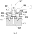
- FIG. 2 is a schematic view of a conventional guiding implanting device.
- a tooth mold fastener 200 also called a guiding plate
- the tooth mold fastener 200 can provide a drill bit guiding hole 201 corresponding in position to the drilling place.
- a special drill bit 300 is mounted on the handpiece 101.
- the difference between the special drill bit 300 and the conventional drill bit 102 is that the special drill bit 300 has a convex part 302 disposed behind the drill head 301 thereof and having a half diameter higher than that of the drill head 301.
- the drill bit guiding hole 201 has a convex hole 202 corresponding in position to the convex part 302.
- the configuration of the convex hole 202 and the drill bit guiding hole 201 can be used to limit the special drill bit 300 to have an axial displacement only, so as to prevent the handpiece 101 connected to the end of the special drill bit 300 from being shifted or skewed.
- the special drill bit 300 includes a stop block 303 disposed thereon, and the drill bit guiding hole 201 has a stop step 203 corresponding in position to the stop block 303, so that the configuration of the stop block 303 and the stop step 203 can limit a drilling depth of the drill head 301 of the special drill bit 300, thereby ensuring accuracy and safety of the dental implant operation.
- a pad or bush made of metal material can be disposed in the drill bit guiding hole 201, so as to solve the problem that the drill bit guiding hole 201 is worn and deformed.
- the implementation of the special drill bit 300 has following problems.
- the special drill bit 300 with the convex part 302 greatly increases a manufacturing cost of the drill bit.
- the dentist must prepare both of the conventional drill bit set and the special drill bit set for dental implant operation, and it results in an increase in medical costs.
- the configuration of the special drill bit 300 and the drill bit guiding hole 201 can stabilize the operating direction of the special drill bit 300, but it causes the problem of greatly increasing the working space required for dental implanting operation, especially a total working distance from a rear end of the handpiece head of the handpiece 101 to a tip of the drill head 301.
- the use of the special drill bit 300 also has the following problems.
- the special drill bit 300 is rotating fast and possibly produces improper friction between the convex part 302 and the convex hole 202, and between the stop block 303 and the stop step 203, and it consumes excessive driving power provided by the handpiece 101; furthermore, the special drill bit 300 generates high temperature during operation, but an outer wall of the drill bit guiding hole 201 blocks the cooling water sprayed from a spray hole 104 of the handpiece 101, so it causes the problem that the special drill bit 300 is not easily lubricated and cooled.
- the configuration of the convex part 302 and the convex hole 202 can prevent the special drill bit 300 from being shifted and skewed, but the convex part 302 also becomes a forced position of the special drill bit 300 for resisting a lateral external force; in other words, all unstable forces of the hand-held handpiece 101 are transferred to the middle section of the special drill bit 300, it causes the special drill bit 300 to be easily damaged, and the convex part 302 and the stop block 303 easily become break points of the special drill bit 300.
- the present invention provides a dental implant guiding tool set and a dental implant guiding sleeve thereof, to solve the conventional technical problems and further improve the implementation of the guiding dental implant technology, so that the conventional dental implant drill bit can be directly used for guiding dental implant operation.
- An objective of the present invention is to provide a dental implant guiding tool set, to enable a general implant drill bit to be directly used for guiding dental implant operation, and to effectively reduce the required operation space, thereby making the dental implant operation easier, safer and more comfortable.
- a dental implant guiding tool set of claim 1 is provided.
- Advantageous embodiments are subject matter of the dependent claims.
- the dental implant guiding tool set comprises a handpiece, a dental implant guiding sleeve, and a tooth mold fastening device.
- the handpiece includes a replaceable drill bit and a handpiece head configured to provide the drill bit with driving power, a connection handle connected to the handpiece head.
- the dental implant guiding sleeve of the present application has a handpiece head guiding hole corresponding to a shape of the handpiece head and disposed axially, at least one lateral opening formed on a side of the handpiece head guiding hole and corresponding in position to the connection handle, two locating plates radially disposed on two outer sides thereof, and a position-limiting plate disposed on a bottom of the handpiece head guiding hole and having a drill bit through hole formed on a center thereof.
- the tooth mold fastening device includes a sleeve hole corresponding to the dental implant guiding sleeve and configured for insertion of the dental implant guiding sleeve, and two locating accommodation spaces formed on two sides of the sleeve hole and corresponding to the two locating plates.
- the handpiece head can be located through the handpiece head guiding hole and limited to have the axial displacement only, so that the drilling position of the drill bit can be precisely controlled; furthermore, the handpiece head contacts the handpiece head guiding hole by a non-rotating outer part thereof, so only sliding friction occurs between the handpiece head and the handpiece head guiding hole during the axial displacement of the handpiece head, thereby preventing the fast rotary friction occurred in the conventional guiding dental implanting device and high heat.
- the configuration of the two locating plates and the two locating accommodation spaces can fasten the dental implant guiding sleeve on the tooth mold fastening device fast and stably, and also can effectively prevent the dental implant guiding sleeve from being affected by the handpiece head to fall off the tooth mold fastening device when the handpiece head is axially moved in the handpiece head guiding hole.
- the drill bit since the drill bit is not direct contact with the dental implant guiding sleeve, it can prevent the middle part of the drill bit from being subjected to an improper force, and the displacement and deflected force of the handpiece can be directly applied to between the handpiece head and the handpiece head guiding hole, and then be eliminated, so as to protect the drill bit well.
- the lateral opening can make the handpiece head enter the handpiece head guiding hole deeper, and the cooling water sprayed from the spray hole of the handpiece can be sprayed to the drill bit through the lateral opening, so as to ensure the drill bit to be lubricated and cooled during operation.
- the position-limiting plate has the drill bit through hole disposed thereon, so that the position-limiting plate contacts the non-rotating handpiece head only and does not interfere with the operation of the drill bit.
- the drill bit through hole can appropriately limit, guide and align the front end of the drill bit.
- the dental implant guiding sleeve can include at least one reinforcing rib disposed on an outer edge thereof and configured to strengthen structural intensity of the dental implant guiding sleeve.
- the tooth mold fastening device can wrap a partial area of the reinforcing rib to prevent the dental implant guiding sleeve from being deformed easily; in an embodiment, the two locating plates can be disposed on the same or difference horizontal heights, so as to fit with teeth near the dental implant position and having different heights; in an embodiment, the dental implant guiding sleeve can be formed by metal material, to make the dental implant guiding sleeve sturdier and more durable for repeatedly use.
- the dental implant guiding sleeve can be in cooperation with the handpiece alone or in cooperation with both of the handpiece and the tooth mold fastening device in the dental implant guiding operation, so as to effectively reduce the required operating space and make the dental implant operation easier, safer and more comfortable.
- the dental implant guiding sleeve of the present invention comprises a handpiece head guiding hole disposed axially and configured for insertion of the handpiece head, and having an aperture size corresponding to the handpiece head shape, at least one lateral opening disposed on a side of the handpiece head guiding hole, and a position-limiting plate disposed on a bottom of the handpiece head guiding hole.
- the position-limiting plate includes a drill bit through hole disposed on a center thereof.
- the handpiece head can be located by the handpiece head guiding hole, and limited to have axial displacement only, so that the drilling position of the drill bit can be precisely controlled; furthermore, the handpiece head contacts the handpiece head guiding hole by the non-rotating outer part thereof, so only sliding friction occurs during the axial displacement, and the fast rotary friction of the conventional guiding dental implanting device does not occur, and high heat is not generated.
- the aforementioned dental implant guiding sleeve can comprise the two locating plates radially disposed on two outer sides of the dental implant guiding sleeve respectively, and configured to enable the dental implant guiding sleeve to be fast and securely attached to other components or to the periphery of the drilling position.
- the dental implant guiding sleeve can comprise the at least one reinforcing rib disposed on an outer edge thereof and configured to strengthen structural intensity of the dental implant guiding sleeve; in an embodiment, the two locating plates can be disposed on the same or difference horizontal heights to fit with teeth near the dental implant position and having different heights; In an embodiment, the dental implant guiding sleeve can be formed by metal material, to make the dental implant guiding sleeve sturdier and more durable.
- the present invention provides the dental implant guiding tool set and a dental implant guiding sleeve thereof to directly guide the handpiece head of the handpiece, so as to prevent the dental implant guiding sleeve from directly contacting the drill bit mounted on the handpiece, and it does not need to use the dedicated drill bit with the special guiding design.
- the conventional drill bit can also be directly used for guiding dental implant operation, and the operation cost can be decreased, and the minimal required operation space of the dental implant guiding tool set can be reduced, thereby making the operation of the drill bit more stable and secure.
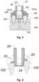
- a dental implant guiding tool set of the present invention includes a handpiece 101, a dental implant guiding sleeve 20 and a tooth mold fastening device 30.
- the handpiece 101 comprises a handpiece head 101a having a replaceable drill bit 102 and configured to provide the drill bit 102 with driving power, and a connection handle 101b connected to the handpiece head 101a.
- the dental implant guiding sleeve 20 includes a handpiece head guiding hole 21 corresponding to a shape of the handpiece head 101a and disposed axially, at least one lateral opening 22 disposed on a side of the handpiece head guiding hole 21 and corresponding in position to the connection handle 101b, two locating plates 23 radially disposed on two outer sides of the dental implant guiding sleeve 20 respectively, and a position-limiting plate 24 disposed on a bottom of the handpiece head guiding hole 21 and having a drill bit through hole 25 formed on a center thereof.
- the dental implant guiding sleeve 20 comprises at least one reinforcing rib 26 disposed on an outer edge thereof and configured to strengthen structural intensity of the dental implant guiding sleeve 20.
- the dental implant guiding sleeve 20 has two lateral openings 22 opposite to each other.
- the lateral opening(s) 22 can be disposed on one side or both sides of the dental implant guiding sleeve 20 according to the use requirements.
- the dental implant guiding sleeve 20 can be made by metal material, to make the dental implant guiding sleeve 20 sturdier and more durable for repeatedly use.
- the tooth mold fastening device 30 comprises a sleeve hole 31 corresponding to the dental implant guiding sleeve 20 and configured for insertion of the dental implant guiding sleeve 20, two locating accommodation spaces 32 formed on two sides of the sleeve hole 31 and corresponding in position to the two locating plates 23.
- the tooth mold fastening device 30 can wrap a partial area of the reinforcing rib 26, to prevent the dental implant guiding sleeve 20 from being deformed easily.
- the handpiece head 101a When the handpiece 101 is operated, the handpiece head 101a is located by the handpiece head guiding hole 21, and limited to have axial displacement only in the handpiece head guiding hole 21, so that the drilling position of the drill bit 102 can be precisely controlled. Since the handpiece head 101a does not rotate, only sliding friction occurs during the axial displacement of above-mentioned operation, so as to prevent unnecessary excessive friction and abrasion and high heat during the operation.
- the dental implant guiding sleeve 20 can be laterally inserted to fast and stably fasten on the tooth mold fastening device 30, and when the handpiece head 101a is axially moved in the handpiece head guiding hole 21, the dental implant guiding sleeve 20 can be effectively prevented from being affected by the handpiece head 101a to fall off the tooth mold fastening device 30.
- the middle section of the drill bit 102 is not subjected to an improper external force, and the displacement and deflected force caused by the handpiece 101 can be directly applied to between the handpiece head 101a and the handpiece head guiding hole 21, and then be eliminated, so as to protect the drill bit 102 well to perform drilling, reaming or grinding operation on the alveolar bone 100.
- the lateral opening 22 enables the handpiece head 101a to enter the handpiece head guiding hole 21 deeper, and the drill bit 102 can be in contact with or located in the handpiece head guiding hole 21 without using any additional structure, so that the required space of the entire implant drilling operation can be greatly reduced and the dental implant operation can be more widely applied in more parts of the mouth, for example, it facilitates to perform the dental implant operation on the rear tooth. Furthermore, the cooling water sprayed from the spray hole 104 of the handpiece 101 can be sprayed to the drill bit 102 through the lateral opening 22, so as to ensures the drill bit 102 to be lubricated and cooled during the operation.
- the position-limiting plate 24 has the drill bit through hole 25, so that the position-limiting plate 24 only contact the non-rotating handpiece head 101a and does not interfere with the operation of the drill bit 102.
- the through hole of the drill bit 102 can properly limit, guide and align the front end of the drill bit 102.
- the dental implant guiding sleeve 20 can be in cooperation with the tooth mold fastening device 30, and also can be used alone in the drilling position for dental implant, so as to directly guide the handpiece head 101a.
- the dental implant operation may be performed on different position, and the teeth near the drilling position possibly have different heights.
- the two locating plates of the dental implant guiding sleeve 20 can be disposed in the same or different levels, and the depth of the position-limiting plate 24 can be different according to the use requirement.
- various types of the dental implant guiding sleeves 20 can be prepared for a dentist to select in different situation.
- FIGS. 9 to 12 show schematic views of the possible implementation types of the reinforcing rib of the present invention.
- the reinforcing rib 26 is used to reinforce the dental implant guiding sleeve 20, to prevent the dental implant guiding sleeve 20 from being deformed by an applied force to cause shrinkage or expansion.
- the shape of the reinforcing rib 26 can vary, and the reinforcing rib 26 can be formed on the dental implant guiding sleeve 20 by welding, soldering or directly stamping manner, to achieve the purpose of structural reinforcement.
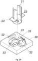
- FIGS. 13 and 14 show the structures of the dental implant guiding sleeve 20 and the tooth mold fastening device 30 according to a second embodiment of the present invention.
- the difference between this embodiment and the first embodiment is that an opening direction of the locating accommodation space 32 formed in the tooth mold fastening device 30 is changed.
- the tooth mold fastening device 30 has rotary guide grooves 33 formed on an upper surface thereof and corresponding to the locating accommodation spaces 32, respectively, so that the bottom of the dental implant guiding sleeve 20 can be directly inserted into the sleeve hole 31 axially, and in this case, the two locating plates 23 are first inserted into the rotary guide grooves 33 and then screwed into the corresponding locating accommodation spaces 32, so that the dental implant guiding sleeve 20 can be stably fastened in the tooth mold fastening device 30.
Landscapes
- Health & Medical Sciences (AREA)
- Oral & Maxillofacial Surgery (AREA)
- Dentistry (AREA)
- Epidemiology (AREA)
- Life Sciences & Earth Sciences (AREA)
- Animal Behavior & Ethology (AREA)
- General Health & Medical Sciences (AREA)
- Public Health (AREA)
- Veterinary Medicine (AREA)
- Orthopedic Medicine & Surgery (AREA)
- Dental Prosthetics (AREA)
- Dental Tools And Instruments Or Auxiliary Dental Instruments (AREA)
Claims (5)
- Zahnimplantat-Führungswerkzeugsatz, umfassend:ein Handstück (101) umfassend einen Handstückkopf (101a), der einen austauschbaren Bohrer (102) aufweist und so konfiguriert ist, dass er den Bohrer mit Antriebskraft versorgt, und einen Verbindungsgriff (101b) der mit dem Handstückkopf (101a) verbunden ist;eine Zahnimplantat-Führungshülse (20) umfassend eine Handstückkopf-Führungsöffnung (21), die zum Einsetzen des Handstückkopfs (101a) konfiguriert ist und eine Öffnungsgröße aufweist, die einer Form des Handstückkopfs (101a) entspricht, mindestens eine seitliche Öffnung (22), die an einer Seite der Handstückkopf-Führungsöffnung (21) angeordnet ist, eine Positionsbegrenzungsplatte (24), die an einem Boden der Handstückkopf-Führungsöffnung (21) angeordnet ist und eine Bohrerdurchgangsöffnung (25) aufweist, die in ihrer Mitte ausgebildet ist, und zwei Fixierungsplatten (23), die jeweils radial an zwei Außenseiten der Zahnimplantat-Führungshülse (20) angeordnet sind, wobei die Handstückkopf-Führungsöffnung (21) der Form des Handstückkopfs (101a) entspricht und axial angeordnet ist, wobei die mindestens eine seitliche Öffnung (22) in ihrer Position dem Verbindungsgriff (101b) entspricht; undeine Zahnform-Befestigungsvorrichtung (30), die eine der Zahnimplantat-Führungshülse (20) entsprechende und zum Einsetzen der Zahnimplantat-Führungshülse (20) ausgebildete Hülsenöffnung (31) und zwei auf zwei Seiten der Hülsenöffnung (31) ausgebildete und in ihrer Position den beiden Fixierungsplatten (23) entsprechende Fixierungsaufnahmeräume (32) umfasst.
- Zahnimplantat-Führungswerkzeugsatz nach Anspruch 1, wobei die Zahnimplantat-Führungshülse (20) mindestens eine Verstärkungsrippe (26) umfasst, die an einem äußeren Rand derselben angeordnet ist.
- Zahnimplantat-Führungswerkzeugsatz nach Anspruch 2, wobei die ZahnformBefestigungsvorrichtung (30) einen Teilbereich der Verstärkungsrippe (26) umschließt.
- Zahnimplantat-Führungswerkzeugsatz nach Anspruch 1, wobei die beiden Fixierungsplatten (23) auf unterschiedlichen horizontalen Höhen angeordnet sind.
- Zahnimplantat-Führungswerkzeugsatz nach Anspruch 1, wobei die Zahnimplantat-Führungshülse (20) aus einem metallischen Werkstoff gebildet ist.
Applications Claiming Priority (1)
| Application Number | Priority Date | Filing Date | Title |
|---|---|---|---|
| TW108126059A TWI705800B (zh) | 2019-07-23 | 2019-07-23 | 植牙導引工具組及其植牙導引套 |
Publications (3)
| Publication Number | Publication Date |
|---|---|
| EP3769714A1 EP3769714A1 (de) | 2021-01-27 |
| EP3769714B1 true EP3769714B1 (de) | 2024-02-28 |
| EP3769714C0 EP3769714C0 (de) | 2024-02-28 |
Family
ID=71661632
Family Applications (1)
| Application Number | Title | Priority Date | Filing Date |
|---|---|---|---|
| EP20186077.2A Active EP3769714B1 (de) | 2019-07-23 | 2020-07-15 | Zahnimplantatführungswerkzeugsatz |
Country Status (3)
| Country | Link |
|---|---|
| US (1) | US11612453B2 (de) |
| EP (1) | EP3769714B1 (de) |
| TW (1) | TWI705800B (de) |
Families Citing this family (1)
| Publication number | Priority date | Publication date | Assignee | Title |
|---|---|---|---|---|
| CN112972026A (zh) * | 2021-02-07 | 2021-06-18 | 苏州辰熠生物科技有限公司 | 一种扭力可调的单向牙齿种植器 |
Citations (1)
| Publication number | Priority date | Publication date | Assignee | Title |
|---|---|---|---|---|
| US20100297574A1 (en) * | 2009-05-20 | 2010-11-25 | Daniel R. Llop | CT-based, Side-loading Surgical and Laboratory Dental Implant Guide System and Methodology of Use |
Family Cites Families (9)
| Publication number | Priority date | Publication date | Assignee | Title |
|---|---|---|---|---|
| US3088745A (en) | 1961-08-30 | 1963-05-07 | Staunt Martin | Plastic bur sleeve for dental handpieces |
| JPH078285B2 (ja) | 1987-12-22 | 1995-02-01 | 弘 大口 | インプラント植立溝形成装置 |
| FR2898485B1 (fr) * | 2006-03-15 | 2008-05-30 | Obl Sa | Dispositif de guidage d'un foret implantaire |
| JP5467726B2 (ja) * | 2007-09-12 | 2014-04-09 | イマグノーシス株式会社 | インプラント植立用穿孔器具、ハンドピース、ハンドピース用アダプタおよびサージカルガイド |
| WO2010025191A1 (en) | 2008-08-29 | 2010-03-04 | Zimmer Dental, Inc. | Dental drill guide system |
| JP4942120B2 (ja) * | 2008-11-17 | 2012-05-30 | 株式会社若吉製作所 | 医療用切削具の案内具 |
| CN102379747B (zh) * | 2011-08-17 | 2014-07-30 | 杭州正驰达精密机械有限公司 | 一种横向进入式种牙导板 |
| KR101631261B1 (ko) * | 2015-03-09 | 2016-06-16 | 주식회사 디오 | 개구부를 가지는 치과 임플란트용 서지컬 가이드 |
| TWM589541U (zh) * | 2019-07-23 | 2020-01-21 | 巧藝國際有限公司 | 植牙導引工具組及其植牙導引套 |
-
2019
- 2019-07-23 TW TW108126059A patent/TWI705800B/zh active
- 2019-08-19 US US16/544,339 patent/US11612453B2/en active Active
-
2020
- 2020-07-15 EP EP20186077.2A patent/EP3769714B1/de active Active
Patent Citations (1)
| Publication number | Priority date | Publication date | Assignee | Title |
|---|---|---|---|---|
| US20100297574A1 (en) * | 2009-05-20 | 2010-11-25 | Daniel R. Llop | CT-based, Side-loading Surgical and Laboratory Dental Implant Guide System and Methodology of Use |
Also Published As
| Publication number | Publication date |
|---|---|
| US11612453B2 (en) | 2023-03-28 |
| EP3769714A1 (de) | 2021-01-27 |
| EP3769714C0 (de) | 2024-02-28 |
| TW202103650A (zh) | 2021-02-01 |
| US20210022829A1 (en) | 2021-01-28 |
| TWI705800B (zh) | 2020-10-01 |
Similar Documents
| Publication | Publication Date | Title |
|---|---|---|
| US12036090B2 (en) | Drill for dental implant | |
| JP5324926B2 (ja) | ドリル工具並びにその工具ヘッド | |
| JP6449769B2 (ja) | 関連ツールを含む外科用トルク伝達器具 | |
| US8821159B2 (en) | Dental implant guiding device | |
| JP5751817B2 (ja) | ガイド手術用の歯科用ツール | |
| JPH07231898A (ja) | 歯科用切削工具の把持装置 | |
| JP6989883B1 (ja) | ドリル補助装置、スクリューガイド装置および歯科矯正器具の取り付け補助装置セット | |
| KR20100066506A (ko) | 임플란트 식립용 천공기구, 핸드피스, 핸드피스용 어댑터 및 서지컬 가이드 | |
| BRPI0613218A2 (pt) | configuração ajustável de acionamento de ferramenta odontológica | |
| JP5491180B2 (ja) | 医療デバイス | |
| JP2015527150A (ja) | 関連ツールを含む外科用トルク伝達器具 | |
| EP3769714A1 (de) | Zahnimplantatführungswerkzeugsatz und zahnimplantatführungshülse dafür | |
| TWM589541U (zh) | 植牙導引工具組及其植牙導引套 | |
| CN111700691A (zh) | 一种牙钻组件 | |
| US7575432B2 (en) | Torque transmission for a surgical or dental rotating tool | |
| EP2537611A1 (de) | Drehwerkzeuginstallations- und entfernungsvorrichtung und drehwerkzeug | |
| JP2015527151A (ja) | 関連ツールを含む外科用トルク伝達器具 | |
| KR102638863B1 (ko) | 치아 임플란트용 드릴장치 | |
| KR102648312B1 (ko) | 치과용 주수 드릴 | |
| CN211023205U (zh) | 植牙导引工具组及其植牙导引套 | |
| KR20210033211A (ko) | 치과 임플란트용 드릴 | |
| TWM612955U (zh) | 機頭限位導引筒狀結構及其工具組 | |
| CN112274272A (zh) | 植牙导引工具组及其植牙导引套 | |
| JP4524448B2 (ja) | 医療用回転切削器具のアタッチメント | |
| TWI763053B (zh) | 機頭限位導引筒狀結構及其植牙限位工具組和植牙導引限位工具組 |
Legal Events
| Date | Code | Title | Description |
|---|---|---|---|
| PUAI | Public reference made under article 153(3) epc to a published international application that has entered the european phase |
Free format text: ORIGINAL CODE: 0009012 |
|
| STAA | Information on the status of an ep patent application or granted ep patent |
Free format text: STATUS: THE APPLICATION HAS BEEN PUBLISHED |
|
| AK | Designated contracting states |
Kind code of ref document: A1 Designated state(s): AL AT BE BG CH CY CZ DE DK EE ES FI FR GB GR HR HU IE IS IT LI LT LU LV MC MK MT NL NO PL PT RO RS SE SI SK SM TR |
|
| AX | Request for extension of the european patent |
Extension state: BA ME |
|
| STAA | Information on the status of an ep patent application or granted ep patent |
Free format text: STATUS: REQUEST FOR EXAMINATION WAS MADE |
|
| 17P | Request for examination filed |
Effective date: 20210727 |
|
| RBV | Designated contracting states (corrected) |
Designated state(s): AL AT BE BG CH CY CZ DE DK EE ES FI FR GB GR HR HU IE IS IT LI LT LU LV MC MK MT NL NO PL PT RO RS SE SI SK SM TR |
|
| STAA | Information on the status of an ep patent application or granted ep patent |
Free format text: STATUS: EXAMINATION IS IN PROGRESS |
|
| 17Q | First examination report despatched |
Effective date: 20221026 |
|
| GRAP | Despatch of communication of intention to grant a patent |
Free format text: ORIGINAL CODE: EPIDOSNIGR1 |
|
| STAA | Information on the status of an ep patent application or granted ep patent |
Free format text: STATUS: GRANT OF PATENT IS INTENDED |
|
| INTG | Intention to grant announced |
Effective date: 20230922 |
|
| GRAS | Grant fee paid |
Free format text: ORIGINAL CODE: EPIDOSNIGR3 |
|
| GRAA | (expected) grant |
Free format text: ORIGINAL CODE: 0009210 |
|
| STAA | Information on the status of an ep patent application or granted ep patent |
Free format text: STATUS: THE PATENT HAS BEEN GRANTED |
|
| AK | Designated contracting states |
Kind code of ref document: B1 Designated state(s): AL AT BE BG CH CY CZ DE DK EE ES FI FR GB GR HR HU IE IS IT LI LT LU LV MC MK MT NL NO PL PT RO RS SE SI SK SM TR |
|
| REG | Reference to a national code |
Ref country code: GB Ref legal event code: FG4D |
|
| REG | Reference to a national code |
Ref country code: CH Ref legal event code: EP |
|
| REG | Reference to a national code |
Ref country code: DE Ref legal event code: R096 Ref document number: 602020026307 Country of ref document: DE |
|
| REG | Reference to a national code |
Ref country code: IE Ref legal event code: FG4D |
|
| U01 | Request for unitary effect filed |
Effective date: 20240327 |
|
| U07 | Unitary effect registered |
Designated state(s): AT BE BG DE DK EE FI FR IT LT LU LV MT NL PT SE SI Effective date: 20240410 |
|
| PG25 | Lapsed in a contracting state [announced via postgrant information from national office to epo] |
Ref country code: IS Free format text: LAPSE BECAUSE OF FAILURE TO SUBMIT A TRANSLATION OF THE DESCRIPTION OR TO PAY THE FEE WITHIN THE PRESCRIBED TIME-LIMIT Effective date: 20240628 |
|
| PG25 | Lapsed in a contracting state [announced via postgrant information from national office to epo] |
Ref country code: GR Free format text: LAPSE BECAUSE OF FAILURE TO SUBMIT A TRANSLATION OF THE DESCRIPTION OR TO PAY THE FEE WITHIN THE PRESCRIBED TIME-LIMIT Effective date: 20240529 |
|
| PG25 | Lapsed in a contracting state [announced via postgrant information from national office to epo] |
Ref country code: HR Free format text: LAPSE BECAUSE OF FAILURE TO SUBMIT A TRANSLATION OF THE DESCRIPTION OR TO PAY THE FEE WITHIN THE PRESCRIBED TIME-LIMIT Effective date: 20240228 Ref country code: RS Free format text: LAPSE BECAUSE OF FAILURE TO SUBMIT A TRANSLATION OF THE DESCRIPTION OR TO PAY THE FEE WITHIN THE PRESCRIBED TIME-LIMIT Effective date: 20240528 |
|
| PG25 | Lapsed in a contracting state [announced via postgrant information from national office to epo] |
Ref country code: ES Free format text: LAPSE BECAUSE OF FAILURE TO SUBMIT A TRANSLATION OF THE DESCRIPTION OR TO PAY THE FEE WITHIN THE PRESCRIBED TIME-LIMIT Effective date: 20240228 |
|
| PG25 | Lapsed in a contracting state [announced via postgrant information from national office to epo] |
Ref country code: RS Free format text: LAPSE BECAUSE OF FAILURE TO SUBMIT A TRANSLATION OF THE DESCRIPTION OR TO PAY THE FEE WITHIN THE PRESCRIBED TIME-LIMIT Effective date: 20240528 Ref country code: NO Free format text: LAPSE BECAUSE OF FAILURE TO SUBMIT A TRANSLATION OF THE DESCRIPTION OR TO PAY THE FEE WITHIN THE PRESCRIBED TIME-LIMIT Effective date: 20240528 Ref country code: IS Free format text: LAPSE BECAUSE OF FAILURE TO SUBMIT A TRANSLATION OF THE DESCRIPTION OR TO PAY THE FEE WITHIN THE PRESCRIBED TIME-LIMIT Effective date: 20240628 Ref country code: HR Free format text: LAPSE BECAUSE OF FAILURE TO SUBMIT A TRANSLATION OF THE DESCRIPTION OR TO PAY THE FEE WITHIN THE PRESCRIBED TIME-LIMIT Effective date: 20240228 Ref country code: GR Free format text: LAPSE BECAUSE OF FAILURE TO SUBMIT A TRANSLATION OF THE DESCRIPTION OR TO PAY THE FEE WITHIN THE PRESCRIBED TIME-LIMIT Effective date: 20240529 Ref country code: ES Free format text: LAPSE BECAUSE OF FAILURE TO SUBMIT A TRANSLATION OF THE DESCRIPTION OR TO PAY THE FEE WITHIN THE PRESCRIBED TIME-LIMIT Effective date: 20240228 |
|
| PG25 | Lapsed in a contracting state [announced via postgrant information from national office to epo] |
Ref country code: PL Free format text: LAPSE BECAUSE OF FAILURE TO SUBMIT A TRANSLATION OF THE DESCRIPTION OR TO PAY THE FEE WITHIN THE PRESCRIBED TIME-LIMIT Effective date: 20240228 |
|
| PG25 | Lapsed in a contracting state [announced via postgrant information from national office to epo] |
Ref country code: PL Free format text: LAPSE BECAUSE OF FAILURE TO SUBMIT A TRANSLATION OF THE DESCRIPTION OR TO PAY THE FEE WITHIN THE PRESCRIBED TIME-LIMIT Effective date: 20240228 |
|
| U20 | Renewal fee for the european patent with unitary effect paid |
Year of fee payment: 5 Effective date: 20240726 |
|
| PG25 | Lapsed in a contracting state [announced via postgrant information from national office to epo] |
Ref country code: SM Free format text: LAPSE BECAUSE OF FAILURE TO SUBMIT A TRANSLATION OF THE DESCRIPTION OR TO PAY THE FEE WITHIN THE PRESCRIBED TIME-LIMIT Effective date: 20240228 |
|
| PG25 | Lapsed in a contracting state [announced via postgrant information from national office to epo] |
Ref country code: CZ Free format text: LAPSE BECAUSE OF FAILURE TO SUBMIT A TRANSLATION OF THE DESCRIPTION OR TO PAY THE FEE WITHIN THE PRESCRIBED TIME-LIMIT Effective date: 20240228 |
|
| PG25 | Lapsed in a contracting state [announced via postgrant information from national office to epo] |
Ref country code: SK Free format text: LAPSE BECAUSE OF FAILURE TO SUBMIT A TRANSLATION OF THE DESCRIPTION OR TO PAY THE FEE WITHIN THE PRESCRIBED TIME-LIMIT Effective date: 20240228 |
|
| PG25 | Lapsed in a contracting state [announced via postgrant information from national office to epo] |
Ref country code: SM Free format text: LAPSE BECAUSE OF FAILURE TO SUBMIT A TRANSLATION OF THE DESCRIPTION OR TO PAY THE FEE WITHIN THE PRESCRIBED TIME-LIMIT Effective date: 20240228 Ref country code: SK Free format text: LAPSE BECAUSE OF FAILURE TO SUBMIT A TRANSLATION OF THE DESCRIPTION OR TO PAY THE FEE WITHIN THE PRESCRIBED TIME-LIMIT Effective date: 20240228 Ref country code: RO Free format text: LAPSE BECAUSE OF FAILURE TO SUBMIT A TRANSLATION OF THE DESCRIPTION OR TO PAY THE FEE WITHIN THE PRESCRIBED TIME-LIMIT Effective date: 20240228 Ref country code: CZ Free format text: LAPSE BECAUSE OF FAILURE TO SUBMIT A TRANSLATION OF THE DESCRIPTION OR TO PAY THE FEE WITHIN THE PRESCRIBED TIME-LIMIT Effective date: 20240228 |
|
| REG | Reference to a national code |
Ref country code: DE Ref legal event code: R097 Ref document number: 602020026307 Country of ref document: DE |
|
| PLBE | No opposition filed within time limit |
Free format text: ORIGINAL CODE: 0009261 |
|
| STAA | Information on the status of an ep patent application or granted ep patent |
Free format text: STATUS: NO OPPOSITION FILED WITHIN TIME LIMIT |
|
| 26N | No opposition filed |
Effective date: 20241129 |
|
| PG25 | Lapsed in a contracting state [announced via postgrant information from national office to epo] |
Ref country code: MC Free format text: LAPSE BECAUSE OF FAILURE TO SUBMIT A TRANSLATION OF THE DESCRIPTION OR TO PAY THE FEE WITHIN THE PRESCRIBED TIME-LIMIT Effective date: 20240228 |
|
| REG | Reference to a national code |
Ref country code: CH Ref legal event code: PL |
|
| GBPC | Gb: european patent ceased through non-payment of renewal fee |
Effective date: 20240715 |
|
| PG25 | Lapsed in a contracting state [announced via postgrant information from national office to epo] |
Ref country code: CH Free format text: LAPSE BECAUSE OF NON-PAYMENT OF DUE FEES Effective date: 20240731 |
|
| PG25 | Lapsed in a contracting state [announced via postgrant information from national office to epo] |
Ref country code: GB Free format text: LAPSE BECAUSE OF NON-PAYMENT OF DUE FEES Effective date: 20240715 |
|
| PG25 | Lapsed in a contracting state [announced via postgrant information from national office to epo] |
Ref country code: IE Free format text: LAPSE BECAUSE OF NON-PAYMENT OF DUE FEES Effective date: 20240715 |
|
| U20 | Renewal fee for the european patent with unitary effect paid |
Year of fee payment: 6 Effective date: 20250711 |
|
| PG25 | Lapsed in a contracting state [announced via postgrant information from national office to epo] |
Ref country code: CY Free format text: LAPSE BECAUSE OF FAILURE TO SUBMIT A TRANSLATION OF THE DESCRIPTION OR TO PAY THE FEE WITHIN THE PRESCRIBED TIME-LIMIT; INVALID AB INITIO Effective date: 20200715 |
|
| PG25 | Lapsed in a contracting state [announced via postgrant information from national office to epo] |
Ref country code: HU Free format text: LAPSE BECAUSE OF FAILURE TO SUBMIT A TRANSLATION OF THE DESCRIPTION OR TO PAY THE FEE WITHIN THE PRESCRIBED TIME-LIMIT; INVALID AB INITIO Effective date: 20200715 |