EP3769560B1 - Qos support in wireless backhaul networks using cellular radio-access technologies - Google Patents
Qos support in wireless backhaul networks using cellular radio-access technologies Download PDFInfo
- Publication number
- EP3769560B1 EP3769560B1 EP19710515.8A EP19710515A EP3769560B1 EP 3769560 B1 EP3769560 B1 EP 3769560B1 EP 19710515 A EP19710515 A EP 19710515A EP 3769560 B1 EP3769560 B1 EP 3769560B1
- Authority
- EP
- European Patent Office
- Prior art keywords
- radio channel
- priority
- packets
- backhaul
- header
- Prior art date
- Legal status (The legal status is an assumption and is not a legal conclusion. Google has not performed a legal analysis and makes no representation as to the accuracy of the status listed.)
- Active
Links
Images


Classifications
-
- H—ELECTRICITY
- H04—ELECTRIC COMMUNICATION TECHNIQUE
- H04W—WIRELESS COMMUNICATION NETWORKS
- H04W28/00—Network traffic management; Network resource management
- H04W28/02—Traffic management, e.g. flow control or congestion control
- H04W28/0268—Traffic management, e.g. flow control or congestion control using specific QoS parameters for wireless networks, e.g. QoS class identifier [QCI] or guaranteed bit rate [GBR]
-
- H—ELECTRICITY
- H04—ELECTRIC COMMUNICATION TECHNIQUE
- H04W—WIRELESS COMMUNICATION NETWORKS
- H04W28/00—Network traffic management; Network resource management
- H04W28/16—Central resource management; Negotiation of resources or communication parameters, e.g. negotiating bandwidth or QoS [Quality of Service]
- H04W28/24—Negotiating SLA [Service Level Agreement]; Negotiating QoS [Quality of Service]
-
- H—ELECTRICITY
- H04—ELECTRIC COMMUNICATION TECHNIQUE
- H04B—TRANSMISSION
- H04B7/00—Radio transmission systems, i.e. using radiation field
- H04B7/14—Relay systems
- H04B7/15—Active relay systems
- H04B7/155—Ground-based stations
- H04B7/15528—Control of operation parameters of a relay station to exploit the physical medium
- H04B7/15542—Selecting at relay station its transmit and receive resources
-
- H—ELECTRICITY
- H04—ELECTRIC COMMUNICATION TECHNIQUE
- H04W—WIRELESS COMMUNICATION NETWORKS
- H04W28/00—Network traffic management; Network resource management
- H04W28/02—Traffic management, e.g. flow control or congestion control
- H04W28/0252—Traffic management, e.g. flow control or congestion control per individual bearer or channel
- H04W28/0263—Traffic management, e.g. flow control or congestion control per individual bearer or channel involving mapping traffic to individual bearers or channels, e.g. traffic flow template [TFT]
-
- H—ELECTRICITY
- H04—ELECTRIC COMMUNICATION TECHNIQUE
- H04W—WIRELESS COMMUNICATION NETWORKS
- H04W40/00—Communication routing or communication path finding
- H04W40/02—Communication route or path selection, e.g. power-based or shortest path routing
- H04W40/22—Communication route or path selection, e.g. power-based or shortest path routing using selective relaying for reaching a BTS [Base Transceiver Station] or an access point
-
- H—ELECTRICITY
- H04—ELECTRIC COMMUNICATION TECHNIQUE
- H04W—WIRELESS COMMUNICATION NETWORKS
- H04W72/00—Local resource management
- H04W72/50—Allocation or scheduling criteria for wireless resources
- H04W72/56—Allocation or scheduling criteria for wireless resources based on priority criteria
-
- H—ELECTRICITY
- H04—ELECTRIC COMMUNICATION TECHNIQUE
- H04W—WIRELESS COMMUNICATION NETWORKS
- H04W76/00—Connection management
- H04W76/10—Connection setup
- H04W76/11—Allocation or use of connection identifiers
-
- H—ELECTRICITY
- H04—ELECTRIC COMMUNICATION TECHNIQUE
- H04W—WIRELESS COMMUNICATION NETWORKS
- H04W76/00—Connection management
- H04W76/10—Connection setup
- H04W76/12—Setup of transport tunnels
-
- H—ELECTRICITY
- H04—ELECTRIC COMMUNICATION TECHNIQUE
- H04W—WIRELESS COMMUNICATION NETWORKS
- H04W84/00—Network topologies
- H04W84/02—Hierarchically pre-organised networks, e.g. paging networks, cellular networks, WLAN [Wireless Local Area Network] or WLL [Wireless Local Loop]
- H04W84/04—Large scale networks; Deep hierarchical networks
- H04W84/042—Public Land Mobile systems, e.g. cellular systems
- H04W84/047—Public Land Mobile systems, e.g. cellular systems using dedicated repeater stations
-
- H—ELECTRICITY
- H04—ELECTRIC COMMUNICATION TECHNIQUE
- H04W—WIRELESS COMMUNICATION NETWORKS
- H04W88/00—Devices specially adapted for wireless communication networks, e.g. terminals, base stations or access point devices
- H04W88/14—Backbone network devices
-
- H—ELECTRICITY
- H04—ELECTRIC COMMUNICATION TECHNIQUE
- H04W—WIRELESS COMMUNICATION NETWORKS
- H04W88/00—Devices specially adapted for wireless communication networks, e.g. terminals, base stations or access point devices
- H04W88/18—Service support devices; Network management devices
-
- Y—GENERAL TAGGING OF NEW TECHNOLOGICAL DEVELOPMENTS; GENERAL TAGGING OF CROSS-SECTIONAL TECHNOLOGIES SPANNING OVER SEVERAL SECTIONS OF THE IPC; TECHNICAL SUBJECTS COVERED BY FORMER USPC CROSS-REFERENCE ART COLLECTIONS [XRACs] AND DIGESTS
- Y02—TECHNOLOGIES OR APPLICATIONS FOR MITIGATION OR ADAPTATION AGAINST CLIMATE CHANGE
- Y02D—CLIMATE CHANGE MITIGATION TECHNOLOGIES IN INFORMATION AND COMMUNICATION TECHNOLOGIES [ICT], I.E. INFORMATION AND COMMUNICATION TECHNOLOGIES AIMING AT THE REDUCTION OF THEIR OWN ENERGY USE
- Y02D30/00—Reducing energy consumption in communication networks
- Y02D30/70—Reducing energy consumption in communication networks in wireless communication networks
Definitions
- aspects of the present disclosure relate generally to wireless communication networks, and more particularly, to wireless backhaul networks.
- Wireless communication networks are widely deployed to provide various types of communication content such as voice, video, packet data, messaging, broadcast, and so on.
- These systems may be multiple-access systems capable of supporting communication with multiple users by sharing the available system resources (e.g., time, frequency, and power).
- multiple-access systems include code-division multiple access (CDMA) systems, time-division multiple access (TDMA) systems, frequency-division multiple access (FDMA) systems, orthogonal frequency-division multiple access (OFDMA) systems, single-carrier frequency division multiple access (SC-FDMA) systems, and time division synchronous code division multiple access (TD-SCDMA) systems.
- CDMA code-division multiple access
- TDMA time-division multiple access
- FDMA frequency-division multiple access
- OFDMA orthogonal frequency-division multiple access
- SC-FDMA single-carrier frequency division multiple access
- TD-SCDMA time division synchronous code division multiple access
- 5G communications technology can include: enhanced mobile broadband addressing human-centric use cases for access to multimedia content, services and data; ultra-reliable-low latency communications (URLLC) with certain specifications for latency and reliability; and massive machine type communications, which can allow a very large number of connected devices and transmission of a relatively low volume of non-delay-sensitive information.
- URLLC ultra-reliable-low latency communications
- massive machine type communications which can allow a very large number of connected devices and transmission of a relatively low volume of non-delay-sensitive information.
- the present disclosure provides a method of wireless communications for a relay node according to claim 1, a relay node according to claim 2, a method of wireless communications for a donor node according to claim 9, and a donor node according to claim 10.
- Preferred embodiments are subject of the dependent claims.
- the present disclosure includes a method of wireless communications for a relay node to provide quality of service (QoS) over a wireless backhaul.
- the method may include receiving a configuration for a first radio channel with a first priority and a first priority ID, and receiving a configuration for a second radio channel with a second priority and a second priority ID.
- the method may include receiving a configuration for a third radio channel with a first bearer ID and a first mapping to the first priority, and receiving a configuration for a fourth radio channel with a second bearer ID and a second mapping to the second priority.
- the method may include forwarding packets from the third radio channel to the first radio channel based on the first mapping and inserting the first priority ID into a header in the packets from the third radio channel.
- the method may include forwarding packets from the fourth radio channel to the second radio channel based on the second mapping, and inserting the second priority ID into a header in the packets from the fourth radio channel.
- the present disclosure provides a relay node
- the relay node may include a memory and a processor in communication with the memory.
- the processor may be configured to receive a configuration for a first radio channel with a first priority and a first priority ID, and receiving a configuration for a second radio channel with a second priority and a second priority ID.
- the processor may be configured to receive a configuration for a third radio channel with a first mapping to the first priority, and receiving a configuration for a fourth radio channel with a second mapping to the second priority.
- the processor may be configured to forward packets from the third radio channel to the first radio channel based on the first mapping and inserting the first priority ID into a header in the packets from the third radio channel.
- the processor may be configured to forward packets from the fourth radio channel to the second radio channel based on the second mapping, and inserting the second priority ID into a header in the packets from the fourth radio channel.
- the present disclosure includes a method of wireless communications for a donor node.
- the method may include receiving a configuration for a first backhaul radio channel with a first priority and a first priority ID, and receiving a configuration for a second backhaul radio channel with a second priority and a second priority ID.
- the method may include receiving a configuration for a first tunnel with a first bearer ID and a first mapping to the first priority, and receiving a configuration for a second tunnel with a second bearer ID and a second mapping to the second priority.
- the method may include forwarding packets from the first tunnel to the first backhaul radio channel based on the first mapping, and inserting the first priority ID into a header in the packets from the first tunnel.
- the method may include forwarding packets from the second tunnel to the second backhaul radio channel based on the second mapping, and inserting the second priority ID into a header in the packets from the second tunnel.
- the present disclosure includes a donor node.
- the donor node may include means for receiving a configuration for a first backhaul radio channel with a first priority and a first priority ID, and receiving a configuration for a second backhaul radio channel with a second priority and a second priority ID.
- the donor node may include means for receiving a configuration for a first tunnel with a first bearer ID and a first mapping to the first priority, and receiving a configuration for a second tunnel with a second bearer ID and a second mapping to the second priority.
- the donor node may include means for forwarding packets from the first tunnel to the first backhaul radio channel based on the first mapping, and inserting the first priority ID into a header in the packets from the first tunnel.
- the donor node may include means for forwarding packets from the second tunnel to the second backhaul radio channel based on the second mapping, and inserting the second priority ID into a header in the packets from the second tunnel.
- the one or more aspects comprise the features hereinafter fully described and particularly pointed out in the claims.
- the following description and the annexed drawings set forth in detail certain illustrative features of the one or more aspects. These features are indicative, however, of but a few of the various ways in which the principles of various aspects may be employed, and this description is intended to include all such aspects.
- component as used herein may be one of the parts that make up a system, may be hardware, firmware, and/or software stored on a computer-readable medium, and may be divided into other components.
- the present disclosure generally relates to wireless backhaul networks using cellular radio access technologies (RAT) such as Integrated-Access and Backhaul (IAB) networks.
- RAT radio access technologies
- IAB Integrated-Access and Backhaul
- the present disclosure also applies to self-backhauling using cellular technologies.
- the present disclosure addresses a problem relating to quality of service (QoS) support in such wireless backhaul networks.
- UE User equipment
- Cellular RATs support such QoS differentiation via the concept of bearers, where each bearer carries a unique QoS-class-specific priority.
- the QoS-class priorities of the various bearers are enforced by the MAC-layer scheduler.
- QoS-prioritization also needs to be applied to the backhaul link, since the wireless medium is shared among traffic flows pertaining to different QoS-classes.
- a set of service classes is established by a controller for the wireless backhaul. Additionally, the controller establishes, on each backhaul link, a separate RLC-channel (or radio bearer) for each QoS class.
- the controller configures a mapping between each of the UE's access RLC-channels and the corresponding QoS-classes supported on the backhaul links on the relay and a donor communicatively coupled with a wireline (and any intermediate nodes).
- Forwarding packets between the relay and the donor across the backhaul network may be based on a QoS-class identifier, which is carried in an adaptation-layer header inserted into the L2 header stack.
- the adaptation-layer header may further include a bearer ID, a routing ID, and other information.
- the adaptation-layer header may reside above or below a radio link control (RLC) header, or may be merged with the RLC header.
- RLC radio link control
- the adaptation-layer header may also reside above a packet data convergence protocol (PDCP) header or a service data adaptation protocol (SDAP) header or be merged with one of these headers.
- PDCP packet data convergence protocol
- SDAP service data adaptation protocol
- the adaptation-layer header may also be split into two sub-layers, e.g., where one sub-layer carries end-to-end information such as the bearer ID while the other sub-layer carries the QoS-class ID and the routing ID, which is evaluated hop-by-hop. For example, each relay node may need to evaluate the QoS-class ID or the routing ID to determine a next hop, but the bearer ID may only be used by a core network.
- the present disclosure is applicable for central unit (CU) - distributed unit (DU) split architecture, where each relay holds a gNB-DU for access and supports RLC channels or radio bearers on each backhaul link.
- CU central unit
- DU distributed unit
- the disclosure is also applicable to scenarios where each relay holds full gNB functionality on the relay for UE-access.
- CDMA Code Division Multiple Access
- UTRA Universal Terrestrial Radio Access
- CDMA2000 covers IS-2000, IS-95, and IS-856 standards.
- IS-2000 Releases 0 and A are commonly referred to as CDMA2000 1X, 1X, etc.
- IS-856 (TIA-856) is commonly referred to as CDMA2000 1xEV-DO, High Rate Packet Data (HRPD), etc.
- UTRA includes Wideband CDMA (WCDMA) and other variants of CDMA.
- a TDMA system may implement a radio technology such as Global System for Mobile Communications (GSM).
- GSM Global System for Mobile Communications
- An OFDMA system may implement a radio technology such as Ultra Mobile Broadband (UMB), Evolved UTRA (E-UTRA), IEEE 802.11 (Wi-Fi), IEEE 802.16 (WiMAX), IEEE 802.20, Flash-OFDM TM , etc.
- UMB Ultra Mobile Broadband
- E-UTRA Evolved UTRA
- Wi-Fi Wi-Fi
- WiMAX IEEE 802.16
- IEEE 802.20 Flash-OFDM TM
- UMB Ultra Mobile Broadband
- E-UTRA Evolved UTRA
- Wi-Fi Wi-Fi
- WiMAX IEEE 802.16
- IEEE 802.20 Flash-OFDM TM
- UTRA and E-UTRA are part of Universal Mobile Telecommunication System (UMTS).
- 3GPP Long Term Evolution (LTE) and LTE-Advanced (LTE-A) are new releases of
- CDMA2000 and UMB are described in documents from an organization named "3rd Generation Partnership Project 2" (3GPP2).
- 3GPP2 3rd Generation Partnership Project 2
- the techniques described herein may be used for the systems and radio technologies mentioned above as well as other systems and radio technologies, including cellular (e.g., LTE) communications over a shared radio frequency spectrum band.
- LTE Long Term Evolution
- LTE/LTE-A and 5G systems for purposes of example
- LTE and 5G terminology is used in much of the description below, although the techniques may be applicable to other next generation communication systems.
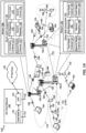
- an example wireless communication network 100 includes at least one base station 102-b, 102-c with a modem 140 having a relay QoS component 150 that provides QoS over a wireless backhaul 134.
- the base stations 102-b and 102-c may not have a direct backhaul link 132 (e.g., NG interface) to the 5G core network 180.
- the term "relay node” may refer to a base station without a direct backhaul link to a core network.
- the term “donor node” may refer to a base station with a direct backhaul link to the core network.
- the wireless communication network 100 also referred to as a wireless wide area network (WWAN) includes at least one base station 102-a with a modem 160 having a donor QoS component 170 that provides QoS for a wireless backhaul 134.
- the base station 102-a may be a donor node that includes a backhaul link 132 to the core network 180.
- the relay nodes of base stations 102-b and 102-c may establish the wireless backhaul 134 via the donor node of base station 102-a.
- the base stations 102 may each be configured with mappings for differentiating packets for transmission over the wireless backhaul 134.
- the base stations 102 may provide QoS differentiation over the wireless backhaul 134.
- the base stations 102 (which may alternatively be referred to as gNodeBs (gNB)) interface with the 5G core network 180 through backhaul links 132 (e.g., NG interface).
- the base stations 102 may perform one or more of the following functions: transfer of user data, radio channel ciphering and deciphering, integrity protection, header compression, mobility control functions (e.g., handover, dual connectivity), inter-cell interference coordination, connection setup and release, load balancing, distribution for non-access stratum (NAS) messages, NAS node selection, synchronization, radio access network (RAN) sharing, multimedia broadcast multicast service (MBMS), subscriber and equipment trace, RAN information management (RIM), paging, positioning, and delivery of warning messages.
- NAS non-access stratum
- RAN radio access network
- MBMS multimedia broadcast multicast service
- RIM RAN information management
- the base stations 102 may communicate directly or indirectly (e.g., through the 5G core network 180) with each other over backhaul links 132, 134 (e.g., X2 interface).
- the backhaul links 132, 134 may be wired or wireless.
- the present disclosure relates to a network where at least some of the backhaul links 134 are wireless.
- the base stations 102 may wirelessly communicate with the UEs 104. Each of the base stations 102 may provide communication coverage for a respective geographic coverage area 110. There may be overlapping geographic coverage areas 110. For example, the small cell 102' may have a coverage area 110' that overlaps the coverage area 110 of one or more macro base stations 102.
- a network that includes both small cell and macro cells may be known as a heterogeneous network.
- a heterogeneous network may also include Home Evolved Node Bs (eNBs) (HeNBs) and/or gNBs, which may provide service to a restricted group known as a closed subscriber group (CSG).
- eNBs Home Evolved Node Bs
- CSG closed subscriber group
- the communication links 120 between the base stations 102 and the UEs 104 may include uplink (UL) (also referred to as reverse link) transmissions from a UE 104 to a base station 102 and/or downlink (DL) (also referred to as forward link) transmissions from a base station 102 to a UE 104.
- UL uplink
- DL downlink
- the communication links 120 may use multiple-input and multiple-output (MIMO) antenna technology, including spatial multiplexing, beamforming, and/or transmit diversity.
- MIMO multiple-input and multiple-output
- the communication links may be through one or more carriers.
- the base stations 102 / UEs 104 may use spectrum up to Y MHz (e.g., 5, 10, 15, 20, 100 MHz) bandwidth per carrier allocated in a carrier aggregation of up to a total of Y ⁇ x MHz (where x is a number of component carriers) used for transmission in each direction.
- the carriers may or may not be adjacent to or contiguous with each other. Allocation of carriers may be asymmetric with respect to DL and UL (e.g., more or less carriers may be allocated for DL than for UL).
- the component carriers may include a primary component carrier and one or more secondary component carriers.
- a primary component carrier may be referred to as a primary cell (PCell) and a secondary component carrier may be referred to as a secondary cell (SCell).
- PCell primary cell
- SCell secondary cell
- D2D communication link 108 may use the DL/LTL WWAN spectrum.
- the D2D communication link 108 may use one or more sidelink channels, such as a physical sidelink broadcast channel (PSBCH), a physical sidelink discovery channel (PSDCH), a physical sidelink shared channel (PSSCH), and a physical sidelink control channel (PSCCH).
- sidelink channels such as a physical sidelink broadcast channel (PSBCH), a physical sidelink discovery channel (PSDCH), a physical sidelink shared channel (PSSCH), and a physical sidelink control channel (PSCCH).
- sidelink channels such as a physical sidelink broadcast channel (PSBCH), a physical sidelink discovery channel (PSDCH), a physical sidelink shared channel (PSSCH), and a physical sidelink control channel (PSCCH).
- sidelink channels such as a physical sidelink broadcast channel (PSBCH), a physical sidelink discovery channel (PSDCH), a physical sidelink shared channel (PSSCH), and a physical sidelink control channel (PSCCH).
- the wireless communications system may further include a Wi-Fi access point (AP) 122 in communication with Wi-Fi stations (STAs) 124 via communication links 126 in a 5 GHz unlicensed frequency spectrum.
- AP Wi-Fi access point
- STAs Wi-Fi stations
- communication links 126 in a 5 GHz unlicensed frequency spectrum.
- the STAs 124 / AP 122 may perform a clear channel assessment (CCA) prior to communicating in order to determine whether the channel is available.
- CCA clear channel assessment
- the small cell 102' may operate in a licensed and/or an unlicensed frequency spectrum. When operating in an unlicensed frequency spectrum, the small cell 102' may employ NR and use the same 5 GHz unlicensed frequency spectrum as used by the Wi-Fi AP 122. The small cell 102', employing NR in an unlicensed frequency spectrum, may boost coverage to and/or increase capacity of the access network.
- the gNodeB (gNB) 106 may operate in millimeter wave (mmW) frequencies and/or near mmW frequencies in communication with the UE 104.
- mmW millimeter wave
- the gNB 106 may be referred to as a mmW base station.
- the gNB 106 may be a gNB distributed unit (gNB-DU) connected to another base station 102 via a wireless backhaul 134.
- Extremely high frequency (EHF) is part of the RF in the electromagnetic spectrum. EHF has a range of 30 GHz to 300 GHz and a wavelength between 1 millimeter and 10 millimeters. Radio waves in the band may be referred to as a millimeter wave.
- Near mmW may extend down to a frequency of 3 GHz with a wavelength of 100 millimeters.
- the super high frequency (SHF) band extends between 3 GHz and 30 GHz, also referred to as centimeter wave. Communications using the mmW / near mmW radio frequency band has extremely high path loss and a short range.
- the mmW gNB 106 may utilize beamforming 184 with the UE 104 to compensate for the extremely high path loss and short range.
- the base station may also be referred to as a gNB, Node B, evolved Node B (eNB), an access point, a base transceiver station, a radio base station, a radio transceiver, a transceiver function, a basic service set (BSS), an extended service set (ESS), or some other suitable terminology.
- the base station 102 provides an access point to the 5G core network 180 for one or more UEs 104.
- Examples of UEs 104 include a cellular phone, a smart phone, a session initiation protocol (SIP) phone, a laptop, a personal digital assistant (PDA), a satellite radio, a global positioning system, a multimedia device, a video device, a digital audio player (e.g., MP3 player), a camera, a game console, a tablet, a smart device, a wearable device, a vehicle, an electric meter, a gas pump, a large or small kitchen appliance, a healthcare device, an implant, a display, or any other similar functioning device.
- Some of the UEs 104 may be referred to as IoT devices (e.g., parking meter, gas pump, toaster, vehicles, heart monitor, etc.).
- the UE 104 may also be referred to as a station, a mobile station, a subscriber station, a mobile unit, a subscriber unit, a wireless unit, a remote unit, a mobile device, a wireless device, a wireless communications device, a remote device, a mobile subscriber station, an access terminal, a mobile terminal, a wireless terminal, a remote terminal, a handset, a user agent, a mobile client, a client, or some other suitable terminology.
- the communication networks may be packet-based networks that operate according to a layered protocol stack and data in the user plane may be based on the IP.
- a user plane protocol stack e.g., packet data convergence protocol (PDCP), radio link control (RLC), MAC, etc.
- PDCP packet data convergence protocol
- RLC radio link control
- MAC MAC
- HARQ hybrid automatic repeat/request
- the RRC protocol layer may provide establishment, configuration, and maintenance of an RRC connection between a UE 104 and the base stations 102.
- the RRC protocol layer may also be used for core network 180 support of radio bearers for the user plane data.
- the transport channels may be mapped to physical channels.
- the base stations 102-b and 102-c may be relay nodes where the modem 140 includes a relay QoS component 150 that maps QoS differentiated data packets between radio channels.
- the base station 102-c may be an access relay node that maps radio access channels to radio backhaul channels and the base station 102-b may be an intermediate relay node that maps backhaul radio channels with a first peer base station (e.g., base station 102-c) to backhaul radio channels with a second peer base station (e.g., base station 102-a).
- a peer base station may refer to a base station with which the base station has established a backhaul link.
- the relay QoS component 150 may include, for example, a configured first radio channel 151 and a configured second radio channel 152 that provide different QoS levels to a UE 104.
- the relay QoS component 150 may further include a configured third radio channel 153 and a configured fourth radio channel 154 that provide different QoS levels over a wireless backhaul 134 to a peer base station.
- the relay QoS component 150 may be configured with a first mapping 155 that maps packets from the first radio channel 151 to the third radio channel 153.
- the relay QoS component 150 may be configured with a second mapping 156 that maps packets from the second radio channel 152 to the fourth radio channel 154.
- the base station 102-a may be a donor node where the modem 160 includes a donor QoS component 170 that maps QoS differentiated data packets between radio channels and tunnels.
- the donor QoS component 170 may include, for example, a configured first radio channel 171 and a configured second radio channel 172 that provide different QoS levels over a wireless backhaul 134 (e.g., to base station 102-b).
- the donor QoS component 170 may further include a configured first tunnel 173 and a configured second tunnel 174 that provide different QoS levels over a wired backhaul link 132 to a core network 180.
- the donor QoS component 170 may be configured with a first mapping 175 that maps packets from the first radio channel 171 to the first tunnel 173.
- the donor QoS component 170 may be configured with a second mapping 176 that maps packets from the second radio channel 172 to the second tunnel 174.
- the donor QoS component 170 and the relay QoS component 150 may establish end-to-end QoS control over the wireless backhaul 134.
- the base stations 102 and the UEs 104 are able to communicate to a network through a 5G core network 180.
- the core network 180 may include an Access and Mobility Management Function/Session Management Function (AMF/SMF) entity 182, User Plane Function (UPF) 184 and other entity or components for communicating packet data units (PDUs).
- AMF/SMF Access and Mobility Management Function/Session Management Function
- UPF User Plane Function
- PDUs packet data units
- the 5G core network 180 may include an Authentication Server Function (AUSF) 192, Unified Data Management (UDM) 194, AMF/SMF entity 182 (shown as two elements), Policy Control Information (PCF) 188 and Application Function (AF) 190, as well as other components for a network (e.g., IP Services 186) to communicate with a UE 104 and a random access network (RAN) (which can include one or more base stations 102).
- AUSF Authentication Server Function
- UDM Unified Data Management
- AMF/SMF entity 182 shown as two elements
- PCF Policy Control Information
- AF Application Function
- the AMF 182 provides several functions including, but not limited to, registration management, connection management, reachability management, mobility management, access authentication, access authorization, location services management, and EPS bearer ID allocation.
- the SMF 182 provides several functions including, but not limited to, session management, UE IP address allocation and management, ARP proxying and/or neighbor solicitation proxying, selection and control of UP function, configures traffic steering at UPF to route traffic to proper destinations, termination of interfaces towards policy control functions, lawful intercepts, control and coordination of charging data collection at the UPF, termination of SM parts of NAS messages, downlink data notification and roaming functionality.
- the UPF 184 provides several functions including, but not limited to, anchor point for intra/inter-RAT mobility, external PDU session point of interconnect to data network (e.g., IP services 186), packet inspection, user plane part of policy rule information, lawful intercepts, traffic usage reporting, QoS handling for user plane, uplink traffic verification, transport level packet marking in the uplink and downlink, sending and forwarding one or more "end marker," and ARP proxying and/or neighbor soliciting proxying.
- the AUSF 192 handles authentication of the components within the 5G core network 180.
- the UDM 194 provides several functions including, but not limited to, generation of authentication credentials, user identification handling, access authorization, support for service/session continuity, subscription management and SMS management.
- the PCF 188 provides several functions including, but not limited to, support for unified policy framework to govern network behavior, provides policy rules to control plane functions for enforcement, and accesses subscription information relevant for policy decision in the Unified Data Repository (UDR).
- the AF 190 provides several functions including, but not limited to, application influence on traffic routing, accessing network exposure function and interacting with policy framework for policy control.
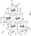
- an example of a wireless backhaul network 200 includes a donor node 210 and several relay nodes 220 providing access to UEs 104.
- Wireless backhauls 214 can provide range extension to a wireline backhaul 212 or fronthaul.
- a wireless backhaul network may support multiple backhaul hops as well as redundant connectivity, e.g. by providing multiple paths between a donor node 210 and a relay node 220.
- the donor node 210 provides the interface between the wireless network and the wireline network (e.g., 5G core network 180 ( Fig. 1A )).
- the wireline network e.g., 5G core network 180 ( Fig. 1A )
- One example for wireless backhauling is Integrated Access and Backhaul (IAB) mentioned in 3GPP Rel-15.
- An access link 222 can support multiple bearers, such as data radio bearers (DRBs) or signaling radio bearers (SRBs). Each bearer may be assigned a different QoS-class and therefore provide a QoS-class-specific priority in data scheduling on the air interface.
- the scheduling decisions may include QoS-class prioritization as well as other predicates such as QoS-class-specific bit-rate- and latency guarantees or bit-rate limits.
- a UE 104 may simultaneously support multiple services pertaining to different QoS-classes through the establishment of multiple bearers where each bearer is assigned with a different QoS class.
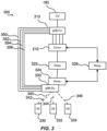
- an example of a wireless backhaul network 300 may extend the wireline fronthaul between a gNB-DU 320 (which may reside at a relay node 220) and gNB-CU 310 (which may reside at the donor node 210 or another network location).
- the wireless backhaul network 300 may include relay nodes 322, 324, 326 and a donor node 210.
- UEs 330, 332, 332 (which may be examples of UE 104) are communicatively coupled with the network via the gNB-DU 320 on relay node 324.
- the UEs 330, 332, 334 sustain radio bearers with the gNB-CU 310, where each radio bearer includes an RLC-channel between a UE 330, 332, or 334 and gNB-DU 320. Each radio bearer may also include a corresponding F1-association 350, 352, 354, 356 between gNB-DU 320 and gNB-CU 310.
- two QoS classes are used by the UEs in Figure 3 .
- UE 330 uses both QoS class 1 and QoS class 2 simultaneously via RLC channels 340 and 342 and therefore has two radio bearers established.
- UE 332 may also use QoS class 1 via RLC channel 344, and UE 334 may use QoS class 2 via RLC channel 346. Accordingly, traffic for UE 330 may share a radio backhaul bearer to gNB-CU 310 with one or both of UE 332 or UE 334.
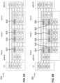
- a network diagram shows how QoS is enforced on the wireless backhaul network 400, which may be similar to the wireless backhaul network 300 shown in FIG. 3 .
- a controller 410 configures a separate RLC-channel (or radio bearer) 360, 362, 364, 366, 368, 370, 372, 374 for each service class supported together with a corresponding QoS-class ID.
- the RLC-channel 360 may support QoS class 1
- the RLC-Channel 362 may support QoS class 2 between relay node 324 and relay node 322.
- the RLC-channel 364 may support QoS class 1
- the RLC-Channel 366 may support QoS class 2 between relay node 322 and donor node 210.
- the RLC-channel 368 may support QoS class 1, and the RLC-Channel 370 may support QoS class 2 between relay node 324 and relay node 326.
- the RLC-channel 372 may support QoS class 1
- the RLC-Channel 374 may support QoS class 2 between relay node 326 and donor node 210.
- Forwarding of user data packets between the relay node 324 and the donor node 210 across the backhaul network may be based on the QoS-class ID which may be carried in an adaptation-layer header inserted into a L2 header stack.
- the adaptation-layer header may further carry a bearer identifier, which may be configured by the controller 410, e.g., the central unit - control (CU-C) plane.
- the adaptation-layer header may further carry a routing ID and potentially other information configured by the controller 410.
- the routing ID may be used by intermediate relay nodes 322, 324 to determine the forwarding direction based on a forwarding table, which is also configured by the controller 410.
- the relay node 324 and the donor node 210 for instance, may use such a routing ID and routing table to determine if data exchange occurs via a first relay node 322 or a second relay node 326.
- the adaptation-layer header may reside above or below the RLC header, or may be merged with the RLC header.
- the adaptation-layer header may also reside above the PDCP header or the SDAP header or be merged with one of these headers.
- the adaptation-layer header may also be split into two layers, e.g. where one carries end-to-end information such as the bearer ID while the other layer carriers the QoS-class ID and the routing ID, both of which are evaluated hop-by-hop.
- information already carried on L2 headers may be used or extended to carry QoS-class ID or routing ID. For instance, the range of the Logical Channel ID (LCID) may be extended and used to interconnect RLC channels or radio bearers in a hop-by-hop manner.
- LCID Logical Channel ID
- the present disclosure is applicable for a central unit (CU)-distributed unit (DU) split architecture, where each relay holds a gNB-DU for access and supports RLC channels or radio bearers on each backhaul link.
- CU central unit
- DU distributed unit
- the present disclosure is also applicable to scenarios where each relay holds full gNB functionality on the relay for UE-access.
- FIGS. 5A-5D examples of protocol stacks that allow QoS-enforcement on the wireless backhaul are illustrated.
- An adaptation layer 512 is inserted into the protocol stack to convey QoS information or routing information.
- the adaptation layer 512 may include a header including priority ID, bearer ID, and/or route ID.
- FIG. 5A shows an example protocol stack 510 for the architecture of FIG. 4 , where a separate RLC channel is established for each QoS class on each backhaul link.
- the adaptation layer 512 is carried on top of the RLC channel in this example.
- the RLC layer is split into a lower portion (RLC-low), which may, e.g., perform segmentation tasks, and a higher portion (RLC-high), which may, e.g., perform automatic repeat request (ARQ).
- the adaptation layer 512 is split into a hop-by-hop adaptation layer (Adapt 1) 522, which may hold QoS-class ID and Route ID, and end-to-end adaptation layer (Adapt 2) 524, which may hold the bearer ID.
- Adapt 1 hop-by-hop adaptation layer
- Adapt 2 end-to-end adaptation layer
- a separate radio bearer is established for each QoS class on each backhaul link.
- the adaptation layer 512 is carried on top of SDAP/PDCP in this example.
- Relay 2 holds a full gNB (CU and DU protocols) instead of just a gNB-DU, and the backhaul communicatively couples the gNB with a UPF.
- the wireless backhaul enforces QoS in the same manner as in FIG. 5C with the adaptation layer 512 carried on top of SDAP/PDCP.
- the donor node may be split into a distributed entity and a centralized entity, which are interconnected via a wireline network, while only the distributed donor entity supports wireless backhaul links.
- the adaptation layer 512 may be terminated at the centralized entity and carried over the wireline entity, e.g., on top of UDP/IP or GTP-U/UDP/IP.
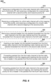
- a method 600 of wireless communication in operating a relay node 220 according to the above-described aspects to provide QoS over a wireless backhaul includes one or more of the herein-defined actions.
- the relay node 220 may include a gNB-DU 320 or may be an intermediate relay node.
- method 600 includes receiving a configuration for a first radio channel with a first priority and a first priority ID, and receiving a configuration for a second radio channel with a second priority and a second priority ID.
- relay node 220 may execute relay QoS component 150 to receive a configuration for a first radio channel 151 with a first priority and a first priority ID, and receive a configuration for a second radio channel 152 with a second priority and a second priority ID, as described herein.
- the configurations may be received from the controller 410.
- the first radio channel and the second radio channel may each be backhaul radio channels to a first peer (e.g., donor node 210).
- the method 600 includes receiving a configuration for a third radio channel with a first bearer ID and a first mapping to the first priority, and receiving a configuration for a fourth radio channel with a second bearer ID and a second mapping to the second priority.
- relay node 220 may execute relay QoS component 150 to receive a configuration from the controller 410 for a third radio channel 153 with a first bearer ID and a first mapping 155 to the first priority, and receive a configuration for a fourth radio channel 154 with a second bearer ID and a second mapping 156 to the second priority.
- the third radio channel 153 and the fourth radio channel 154 may each be access radio channels to a UE 104.
- the relay node 220 is an intermediate relay node, the third radio channel 153 and the fourth radio channel 154 may each be backhaul radio channels to a second peer (e.g., an access relay node).
- the method 600 may optionally include removing a received header from the packets forwarded from the first radio channel to the third radio channel and from the packets forwarded from the second radio channel to the fourth radio channel.
- relay node 220 may execute relay QoS component 150 to remove a received header from the packets forwarded from the first radio channel to the third radio channel and from the packets forwarded from the second radio channel to the fourth radio channel.
- the received header may, for example, include a priority ID and/or bearer ID for a previous hop. By removing the received header, the packet may be routed according to the configured mapping. Further, the received header may be an adaptation layer header that is not applicable to an access radio channel.
- the method 600 may optionally include inserting a new header into the packets forwarded from the third access radio channel to the first backhaul radio channel and into the packets forwarded from the fourth radio channel to the second radio channel.
- relay node 220 may execute relay QoS component 150 to insert a new header into the packets forwarded from the third access radio channel to the first backhaul radio channel and into the packets forwarded from the fourth radio channel to the second radio channel.
- the new header may be an adaptation layer header.
- the new header may include fields for the priority ID and the bearer ID.
- the method 600 includes forwarding packets from the third access radio channel to the first backhaul radio channel based on the first mapping and inserting the first priority ID into a header in the packets from the third access radio channel.
- relay node 220 may execute relay QoS component 150 to forward packets from the third radio channel 153 to the first radio channel 151 based on the first mapping 155 and inserting the first priority ID into a header in the packets from the third radio channel 153, which may be an access radio channel.
- the method 600 includes forwarding packets from the fourth radio channel to the second radio channel based on the second mapping, and inserting the second priority ID into a header in the packets from the fourth radio channel.
- relay node 220 may execute relay QoS component 150 to forward packets from the fourth radio channel 154 to the second radio channel 152 based on the second mapping 156, and insert the second priority ID into a header in the packets from the fourth radio channel.
- a method 700 of wireless communication in operating a donor node 210 according to the above-described aspects to provide QoS over a wireless backhaul includes one or more of the herein-defined actions.
- the donor node 210 may include a wired connection to a gNB-CU 310 including tunnels.
- method 700 includes receiving a configuration for a first backhaul radio channel with a first priority and a first priority ID, and receiving a configuration for a second backhaul radio channel with a second priority and a second priority ID.
- donor node 210 may execute donor QoS component 170 to receive a configuration for a first radio channel 171, which may be a backhaul radio channel, with a first priority and a first priority ID, and receive a configuration for a second radio channel 172, which may also be a backhaul radio channel, with a second priority and a second priority ID, as described herein.
- the configurations may be received from the controller 410.
- the first radio channel 171 and the second radio channel 172 may each be backhaul radio channels to a first peer (e.g., a relay node 220).
- the method 700 includes receiving a configuration for a first tunnel with a first bearer ID and a first mapping to the first priority, and receiving a configuration for a second tunnel with a second bearer ID and a second mapping to the second priority.
- donor node 210 may execute donor QoS component 170 to receive a configuration for a first tunnel 173 with a first bearer ID and a first mapping 175 to the first priority, and receive a configuration for a second tunnel 174 with a second bearer ID and a second mapping 176 to the second priority.
- the method 700 may optionally include removing a received header from packets forwarded from the first radio channel to the first tunnel and from the second radio channel to the second tunnel.
- donor node 210 may execute donor QoS component 170 to remove a received header from packets forwarded from the first radio channel to the first tunnel and from the second radio channel to the second tunnel.
- the received header may, for example, include a priority ID and/or bearer ID for a previous hop. By removing the received header, the packet may be routed according to the configured mapping.
- the method 700 may optionally include inserting a new header into the packets forwarded from the first tunnel to the first radio channel and from the second tunnel to the second radio channel.
- donor node 210 may execute donor QoS component 170 to insert a new header into the packets forwarded from the first tunnel to the first radio channel and from the second tunnel to the second radio channel.
- the new header may be an adaptation layer header.
- the new header may include fields for the priority ID and the bearer ID.
- the method 700 includes forwarding packets from the first tunnel to the first backhaul radio channel based on the first mapping, and inserting the first priority ID into a header in the packets from the first tunnel.
- donor node 210 may execute donor QoS component 170 to forward packets from the first tunnel 173 to the first radio channel 171, which may be a backhaul radio channel, based on the first mapping 175, and insert the first priority ID into a header in the packets from the first tunnel 173.
- the method 700 includes forwarding packets from the second tunnel to the second backhaul radio channel based on the second mapping, and inserting the second priority ID into a header in the packets from the second tunnel.
- donor node 210 may execute donor QoS component 170 to forward packets from the second tunnel 174 to the second radio channel 172, which may be a backhaul radio channel, based on the second mapping 176, and inserting the second priority ID into a header in the packets from the second tunnel.
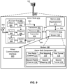
- one example of an implementation of a relay node 220 at a base station 102 may include a variety of components, some of which have already been described above, but including components such as one or more processors 812 and memory 816 and transceiver 802 in communication via one or more buses 844, which may operate in conjunction with modem 140 and relay QoS component 150 to enable one or more of the functions described herein related to providing QoS over a wireless backhaul.
- the one or more processors 812, modem 814, memory 816, transceiver 802, RF front end 888 and one or more antennas 886 may be configured to support voice and/or data calls (simultaneously or non-simultaneously) in one or more radio access technologies.
- the one or more processors 812 can include a modem 814 that uses one or more modem processors.
- the various functions related to relay QoS component 150 may be included in modem 140 and/or processors 812 and, in an aspect, can be executed by a single processor, while in other aspects, different ones of the functions may be executed by a combination of two or more different processors.
- the one or more processors 812 may include any one or any combination of a modem processor, or a baseband processor, or a digital signal processor, or a transmit processor, or a receiver processor, or a transceiver processor associated with transceiver 802. In other aspects, some of the features of the one or more processors 812 and/or modem 140 associated with relay QoS component 150 may be performed by transceiver 802.
- memory 816 may be configured to store data used herein and/or local versions of applications 875 or relay QoS component 150 and/or one or more of its subcomponents being executed by at least one processor 812.
- Memory 816 can include any type of computer-readable medium usable by a computer or at least one processor 812, such as random access memory (RAM), read only memory (ROM), tapes, magnetic discs, optical discs, volatile memory, non-volatile memory, and any combination thereof.
- memory 816 may be a non-transitory computer-readable storage medium that stores one or more computer-executable codes defining relay QoS component 150 and/or one or more of its subcomponents, and/or data associated therewith, when base station 102 is operating at least one processor 812 to execute relay QoS component 150 and/or one or more of its subcomponents.
- Transceiver 802 may include at least one receiver 806 and at least one transmitter 808.
- Receiver 806 may include hardware, firmware, and/or software code executable by a processor for receiving data, the code comprising instructions and being stored in a memory (e.g., computer-readable medium).
- Receiver 806 may be, for example, a radio frequency (RF) receiver.
- RF radio frequency
- receiver 806 may receive signals transmitted by at least one other base station 102. Additionally, receiver 806 may process such received signals, and also may obtain measurements of the signals, such as, but not limited to, Ec/Io, SNR, RSRP, RSSI, etc.
- Transmitter 808 may include hardware, firmware, and/or software code executable by a processor for transmitting data, the code comprising instructions and being stored in a memory (e.g., computer-readable medium).
- a suitable example of transmitter 808 may including, but is not limited to, an RF transmitter.
- relay node 220 may include RF front end 888, which may operate in communication with one or more antennas 865 and transceiver 802 for receiving and transmitting radio transmissions, for example, wireless communications transmitted by at least one UE 104 or wireless transmissions transmitted by another base station 102.
- RF front end 888 may be connected to one or more antennas 865 and can include one or more low-noise amplifiers (LNAs) 890, one or more switches 892, one or more power amplifiers (PAs) 898, and one or more filters 896 for transmitting and receiving RF signals.
- LNAs low-noise amplifiers
- PAs power amplifiers
- LNA 890 can amplify a received signal at a desired output level.
- each LNA 890 may have a specified minimum and maximum gain values.
- RF front end 888 may use one or more switches 892 to select a particular LNA 890 and its specified gain value based on a desired gain value for a particular application.
- one or more PA(s) 898 may be used by RF front end 888 to amplify a signal for an RF output at a desired output power level.
- each PA 898 may have specified minimum and maximum gain values.
- RF front end 888 may use one or more switches 892 to select a particular PA 898 and its specified gain value based on a desired gain value for a particular application.
- one or more filters 896 can be used by RF front end 888 to filter a received signal to obtain an input RF signal.
- a respective filter 896 can be used to filter an output from a respective PA 898 to produce an output signal for transmission.
- each filter 896 can be connected to a specific LNA 890 and/or PA 898.
- RF front end 888 can use one or more switches 892 to select a transmit or receive path using a specified filter 896, LNA 890, and/or PA 898, based on a configuration as specified by transceiver 802 and/or processor 812.
- transceiver 802 may be configured to transmit and receive wireless signals through one or more antennas 865 via RF front end 888.
- transceiver may be tuned to operate at specified frequencies such that relay node 220 can communicate with, for example, one or more UEs 104 or one or more cells associated with one or more base stations 102.
- modem 140 can configure transceiver 802 to operate at a specified frequency and power level based on the base station configuration of the relay node 220 and the communication protocol used by modem 140.
- modem 140 can be a multiband-multimode modem, which can process digital data and communicate with transceiver 802 such that the digital data is sent and received using transceiver 802.
- modem 140 can be multiband and be configured to support multiple frequency bands for a specific communications protocol.
- modem 140 can be multimode and be configured to support multiple operating networks and communications protocols.
- modem 140 can control one or more components of base station 102 (e.g., RF front end 888, transceiver 802) to enable transmission and/or reception of signals from the network based on a specified modem configuration.
- the modem configuration can be based on the mode of the modem and the frequency band in use.
- one example of an implementation of a base station 102 as a donor node 210 may include a variety of components, some of which have already been described above, but including components such as one or more processors 912 and memory 916 and transceiver 902 in communication via one or more buses 944, which may operate in conjunction with modem 160 and donor QoS component 170 to enable one or more of the functions described herein related to providing QoS over a wireless backhaul.
- the donor node 210 may include a wired communication interface 950 which may operate in conjunction with modem 160 and donor QoS component 170 to enable one or more of the functions described herein related to providing QoS for a wireless backhaul terminating at the donor node 210.
- the transceiver 902, receiver 906, transmitter 908, one or more processors 912, memory 916, applications 975, buses 944, RF front end 988, LNAs 990, switches 992, filters 996, PAs 998, and one or more antennas 965 may be the same as or similar to the corresponding components of relay node 220, as described above, but configured or otherwise programmed for donor node operations as opposed to relay node operations.
- Information and signals may be represented using any of a variety of different technologies and techniques.
- data, instructions, commands, information, signals, bits, symbols, and chips that may be referenced throughout the above description may be represented by voltages, currents, electromagnetic waves, magnetic fields or particles, optical fields or particles, computer-executable code or instructions stored on a computer-readable medium, or any combination thereof.
- a specially-programmed device such as but not limited to a processor, a digital signal processor (DSP), an ASIC, a FPGA or other programmable logic device, a discrete gate or transistor logic, a discrete hardware component, or any combination thereof designed to perform the functions described herein.
- DSP digital signal processor
- a specially-programmed processor may be a microprocessor, but in the alternative, the processor may be any conventional processor, controller, microcontroller, or state machine.
- a specially-programmed processor may also be implemented as a combination of computing devices, e.g., a combination of a DSP and a microprocessor, multiple microprocessors, one or more microprocessors in conjunction with a DSP core, or any other such configuration.
- the functions described herein may be implemented in hardware, software executed by a processor, firmware, or any combination thereof. If implemented in software executed by a processor, the functions may be stored on or transmitted over as one or more instructions or code on a non-transitory computer-readable medium. Other examples and implementations are within the scope of the disclosure as defined by the appended claims. For example, due to the nature of software, functions described above can be implemented using software executed by a specially programmed processor, hardware, firmware, hardwiring, or combinations of any of these. Features implementing functions may also be physically located at various positions, including being distributed such that portions of functions are implemented at different physical locations.
- Computer-readable media includes both computer storage media and communication media including any medium that facilitates transfer of a computer program from one place to another.
- a storage medium may be any available medium that can be accessed by a general purpose or special purpose computer.
- computer-readable media can comprise RAM, ROM, EEPROM, CD-ROM or other optical disk storage, magnetic disk storage or other magnetic storage devices, or any other medium that can be used to carry or store desired program code means in the form of instructions or data structures and that can be accessed by a general-purpose or special-purpose computer, or a general-purpose or special-purpose processor.
- any connection is properly termed a computer-readable medium.
- Disk and disc include compact disc (CD), laser disc, optical disc, digital versatile disc (DVD), floppy disk and Blu-ray disc where disks usually reproduce data magnetically, while discs reproduce data optically with lasers. Combinations of the above are also included within the scope of computer-readable media.
Landscapes
- Engineering & Computer Science (AREA)
- Computer Networks & Wireless Communication (AREA)
- Signal Processing (AREA)
- Quality & Reliability (AREA)
- Mobile Radio Communication Systems (AREA)
- Computer And Data Communications (AREA)
- Transition And Organic Metals Composition Catalysts For Addition Polymerization (AREA)
Applications Claiming Priority (3)
| Application Number | Priority Date | Filing Date | Title |
|---|---|---|---|
| US201862645095P | 2018-03-19 | 2018-03-19 | |
| US16/273,610 US10972933B2 (en) | 2018-03-19 | 2019-02-12 | QoS support in wireless backhaul networks using cellular radio-access technologies |
| PCT/US2019/017865 WO2019182694A1 (en) | 2018-03-19 | 2019-02-13 | Qos support in wireless backhaul networks using cellular radio-access technologies |
Publications (2)
| Publication Number | Publication Date |
|---|---|
| EP3769560A1 EP3769560A1 (en) | 2021-01-27 |
| EP3769560B1 true EP3769560B1 (en) | 2023-04-12 |
Family
ID=67906347
Family Applications (1)
| Application Number | Title | Priority Date | Filing Date |
|---|---|---|---|
| EP19710515.8A Active EP3769560B1 (en) | 2018-03-19 | 2019-02-13 | Qos support in wireless backhaul networks using cellular radio-access technologies |
Country Status (10)
| Country | Link |
|---|---|
| US (1) | US10972933B2 (https=) |
| EP (1) | EP3769560B1 (https=) |
| JP (1) | JP7290659B2 (https=) |
| KR (1) | KR102858874B1 (https=) |
| CN (1) | CN111886896B (https=) |
| AU (1) | AU2019237892B2 (https=) |
| BR (1) | BR112020018674A2 (https=) |
| SG (1) | SG11202007936QA (https=) |
| TW (1) | TWI787461B (https=) |
| WO (1) | WO2019182694A1 (https=) |
Families Citing this family (24)
| Publication number | Priority date | Publication date | Assignee | Title |
|---|---|---|---|---|
| CN110351836B (zh) * | 2018-04-03 | 2022-12-13 | 维沃移动通信有限公司 | 中继资源的配置方法和设备 |
| CN110351700B (zh) * | 2018-04-05 | 2022-06-17 | 中兴通讯股份有限公司 | 一种自接入回传链路的中继转发方法及节点 |
| US11064417B2 (en) * | 2018-05-10 | 2021-07-13 | Telefonaktiebolaget Lm Ericsson (Publ) | QoS and hop-aware adaptation layer for multi-hop integrated access backhaul system |
| CN110475368B (zh) | 2018-05-10 | 2022-12-20 | 中兴通讯股份有限公司 | 信息传输方法及装置 |
| CN110475267B (zh) * | 2018-05-11 | 2021-09-17 | 华为技术有限公司 | 一种配置方法、数据传输方法和装置 |
| EP3815324B1 (en) * | 2018-06-26 | 2025-08-20 | Nokia Technologies Oy | Dynamic route selection in integrated access and backhaul system |
| US10939357B2 (en) * | 2018-07-03 | 2021-03-02 | Nokia Solutions And Networks Oy | Integrated access and backhaul adaptation layer status report |
| WO2020022849A1 (en) * | 2018-07-27 | 2020-01-30 | Samsung Electronics Co., Ltd. | Method and apparatus for wireless communication of wireless node in wireless communication system |
| EP4236440A3 (en) * | 2018-08-10 | 2023-10-18 | Ofinno, LLC | Wireless backhaul link information |
| US11057791B2 (en) | 2018-10-30 | 2021-07-06 | At&T Intellectual Property I, L.P. | Configuration and reconfiguration of aggregated backhaul bearers in a multi-hop integrated access backhaul network for 5G or other next generation network |
| GB2581121B (en) * | 2018-10-31 | 2021-06-02 | Tcl Communication Ltd | Bearer mapping in a wireless communications network |
| US10958511B2 (en) * | 2018-11-01 | 2021-03-23 | At&T Intellectual Property I, L.P. | Integrated access backhaul network architecture to support bearer aggregation for 5G or other next generation network |
| US11652719B2 (en) * | 2019-07-18 | 2023-05-16 | Lenovo (Singapore) Pte. Ltd. | Measuring round trip time in a mobile communication network |
| CN114467288A (zh) * | 2019-09-30 | 2022-05-10 | 华为技术有限公司 | 一种数据包传输方法及装置 |
| US11463902B2 (en) * | 2019-10-03 | 2022-10-04 | Qualcomm Incorporated | Quality of service flow mapping handling for the support of V2X communication |
| JP7320673B2 (ja) * | 2019-10-04 | 2023-08-03 | テレフオンアクチーボラゲット エルエム エリクソン(パブル) | 端末間マルチホップサイドリンク無線通信におけるデータパケット伝送実行の方法および装置 |
| WO2021097801A1 (en) * | 2019-11-22 | 2021-05-27 | Mediatek Singapore Pte. Ltd. | Methods and apparatus of packet routing for sidelink relay |
| CN113727453B (zh) * | 2020-05-26 | 2023-09-05 | 中移(成都)信息通信科技有限公司 | 资源调度的方法、装置、系统及存储介质 |
| US11528654B2 (en) * | 2020-06-11 | 2022-12-13 | Qualcomm Incorporated | Transport layer separation in an integrated access and backhaul network |
| US11991615B2 (en) * | 2020-10-22 | 2024-05-21 | Qualcomm Incorporated | Rewriting BAP headers in IAB |
| WO2022133714A1 (zh) * | 2020-12-22 | 2022-06-30 | 华为技术有限公司 | 节点调度方法及装置 |
| CN117044289A (zh) * | 2021-03-31 | 2023-11-10 | 苹果公司 | 对于侧链路中继的服务质量(qos)增强 |
| KR102589554B1 (ko) * | 2021-07-07 | 2023-10-13 | 중앙대학교 산학협력단 | 무선 엣지 컴퓨팅 기반 네트워크에서의 최적의 부분 오프로딩 방법 및 오프로딩을 위한 시스템 |
| US20240284295A1 (en) * | 2023-02-17 | 2024-08-22 | Nokia Technologies Oy | Service routing for user equipment |
Family Cites Families (12)
| Publication number | Priority date | Publication date | Assignee | Title |
|---|---|---|---|---|
| EP2259651A1 (en) | 2009-06-05 | 2010-12-08 | Panasonic Corporation | QoS Multiplexing via base station-relay node interface |
| US8724472B2 (en) * | 2010-03-25 | 2014-05-13 | Qualcomm Incorporated | Data radio bearer mapping in a telecommunication network with relays |
| CN104303472B (zh) * | 2012-05-15 | 2018-03-16 | 马维尔国际贸易有限公司 | 以太网包的扩展优先级 |
| US9432990B2 (en) * | 2013-08-23 | 2016-08-30 | Airties Kablosuz Iletisim San. Ve Dis Tic. A.S. | Hybrid mesh network |
| JP6211998B2 (ja) | 2014-06-19 | 2017-10-11 | Necプラットフォームズ株式会社 | 中継装置、中継方法、およびコンピュータ・プログラム |
| EP3125643B1 (en) | 2015-07-31 | 2019-04-03 | Panasonic Intellectual Property Corporation of America | Improved scheduling mechanism for prose relays serving remote ues |
| US10367677B2 (en) * | 2016-05-13 | 2019-07-30 | Telefonaktiebolaget Lm Ericsson (Publ) | Network architecture, methods, and devices for a wireless communications network |
| US10645689B2 (en) * | 2016-08-11 | 2020-05-05 | Qualcomm Incorporated | Link establishment in a wireless backhaul network using radio access technology |
| US10206232B2 (en) * | 2016-09-29 | 2019-02-12 | At&T Intellectual Property I, L.P. | Initial access and radio resource management for integrated access and backhaul (IAB) wireless networks |
| CN110603880A (zh) * | 2017-05-05 | 2019-12-20 | 华为技术有限公司 | 半持续调度方法、用户设备和网络设备 |
| US10432295B2 (en) * | 2018-01-11 | 2019-10-01 | At&T Intellectual Property I, L.P. | Radio link control layer based relaying for integrated access and backhaul transmissions in wireless networks |
| CN111727577B (zh) * | 2018-02-15 | 2023-04-07 | 瑞典爱立信有限公司 | 集成接入和回程网络中的自适应多址方案 |
-
2019
- 2019-02-12 US US16/273,610 patent/US10972933B2/en active Active
- 2019-02-13 KR KR1020207029621A patent/KR102858874B1/ko active Active
- 2019-02-13 JP JP2020550123A patent/JP7290659B2/ja active Active
- 2019-02-13 CN CN201980019626.8A patent/CN111886896B/zh active Active
- 2019-02-13 BR BR112020018674-0A patent/BR112020018674A2/pt unknown
- 2019-02-13 AU AU2019237892A patent/AU2019237892B2/en active Active
- 2019-02-13 TW TW108104777A patent/TWI787461B/zh active
- 2019-02-13 SG SG11202007936QA patent/SG11202007936QA/en unknown
- 2019-02-13 EP EP19710515.8A patent/EP3769560B1/en active Active
- 2019-02-13 WO PCT/US2019/017865 patent/WO2019182694A1/en not_active Ceased
Also Published As
| Publication number | Publication date |
|---|---|
| CN111886896A (zh) | 2020-11-03 |
| AU2019237892B2 (en) | 2022-07-07 |
| KR102858874B1 (ko) | 2025-09-10 |
| SG11202007936QA (en) | 2020-10-29 |
| CN111886896B (zh) | 2024-01-05 |
| US10972933B2 (en) | 2021-04-06 |
| BR112020018674A2 (pt) | 2020-12-29 |
| JP2021518697A (ja) | 2021-08-02 |
| WO2019182694A1 (en) | 2019-09-26 |
| US20190289492A1 (en) | 2019-09-19 |
| EP3769560A1 (en) | 2021-01-27 |
| AU2019237892A1 (en) | 2020-09-17 |
| JP7290659B2 (ja) | 2023-06-13 |
| TW201939996A (zh) | 2019-10-01 |
| TWI787461B (zh) | 2022-12-21 |
| KR20200133257A (ko) | 2020-11-26 |
Similar Documents
| Publication | Publication Date | Title |
|---|---|---|
| EP3769560B1 (en) | Qos support in wireless backhaul networks using cellular radio-access technologies | |
| US11540274B2 (en) | Efficient signaling of resource pattern in integrated-access and backhaul (IAB) networks | |
| CN111656812B (zh) | 针对eV2X的可靠性请求的基于策略的控制 | |
| EP3698576B1 (en) | Connection gateway selection in a mobile communications device | |
| US20190268815A1 (en) | User plane function (upf) duplication based make before break handover | |
| US20190297529A1 (en) | Extension of logical channel number in cellular radio access technologies | |
| US10638531B2 (en) | Method for operating a new entity for LTE-WLAN aggregation system and a device therefor | |
| CN113424484A (zh) | 用于在多trp中的pdsch tci状态激活-停用的方法和装置 | |
| US10939261B2 (en) | Techniques to interface and route packets in C-V2X devices | |
| US20200351834A1 (en) | Band combination constraint on the number of supported layers | |
| US11825359B2 (en) | Techniques for using simultaneous connectivity for mobility of integrated access and backhaul nodes |
Legal Events
| Date | Code | Title | Description |
|---|---|---|---|
| STAA | Information on the status of an ep patent application or granted ep patent |
Free format text: STATUS: UNKNOWN |
|
| STAA | Information on the status of an ep patent application or granted ep patent |
Free format text: STATUS: THE INTERNATIONAL PUBLICATION HAS BEEN MADE |
|
| PUAI | Public reference made under article 153(3) epc to a published international application that has entered the european phase |
Free format text: ORIGINAL CODE: 0009012 |
|
| STAA | Information on the status of an ep patent application or granted ep patent |
Free format text: STATUS: REQUEST FOR EXAMINATION WAS MADE |
|
| 17P | Request for examination filed |
Effective date: 20201014 |
|
| AK | Designated contracting states |
Kind code of ref document: A1 Designated state(s): AL AT BE BG CH CY CZ DE DK EE ES FI FR GB GR HR HU IE IS IT LI LT LU LV MC MK MT NL NO PL PT RO RS SE SI SK SM TR |
|
| AX | Request for extension of the european patent |
Extension state: BA ME |
|
| DAV | Request for validation of the european patent (deleted) | ||
| DAX | Request for extension of the european patent (deleted) | ||
| REG | Reference to a national code |
Ref country code: DE Ref legal event code: R079 Ref document number: 602019027451 Country of ref document: DE Free format text: PREVIOUS MAIN CLASS: H04W0028240000 Ipc: H04B0007155000 |
|
| GRAP | Despatch of communication of intention to grant a patent |
Free format text: ORIGINAL CODE: EPIDOSNIGR1 |
|
| STAA | Information on the status of an ep patent application or granted ep patent |
Free format text: STATUS: GRANT OF PATENT IS INTENDED |
|
| RIC1 | Information provided on ipc code assigned before grant |
Ipc: H04W 28/08 20090101ALI20221024BHEP Ipc: H04W 28/24 20090101ALI20221024BHEP Ipc: H04W 40/22 20090101ALI20221024BHEP Ipc: H04W 28/02 20090101ALI20221024BHEP Ipc: H04B 7/155 20060101AFI20221024BHEP |
|
| INTG | Intention to grant announced |
Effective date: 20221116 |
|
| GRAS | Grant fee paid |
Free format text: ORIGINAL CODE: EPIDOSNIGR3 |
|
| GRAA | (expected) grant |
Free format text: ORIGINAL CODE: 0009210 |
|
| STAA | Information on the status of an ep patent application or granted ep patent |
Free format text: STATUS: THE PATENT HAS BEEN GRANTED |
|
| AK | Designated contracting states |
Kind code of ref document: B1 Designated state(s): AL AT BE BG CH CY CZ DE DK EE ES FI FR GB GR HR HU IE IS IT LI LT LU LV MC MK MT NL NO PL PT RO RS SE SI SK SM TR |
|
| REG | Reference to a national code |
Ref country code: GB Ref legal event code: FG4D |
|
| REG | Reference to a national code |
Ref country code: CH Ref legal event code: EP |
|
| REG | Reference to a national code |
Ref country code: DE Ref legal event code: R096 Ref document number: 602019027451 Country of ref document: DE |
|
| REG | Reference to a national code |
Ref country code: IE Ref legal event code: FG4D |
|
| REG | Reference to a national code |
Ref country code: AT Ref legal event code: REF Ref document number: 1560364 Country of ref document: AT Kind code of ref document: T Effective date: 20230515 |
|
| REG | Reference to a national code |
Ref country code: LT Ref legal event code: MG9D |
|
| REG | Reference to a national code |
Ref country code: NL Ref legal event code: MP Effective date: 20230412 |
|
| REG | Reference to a national code |
Ref country code: AT Ref legal event code: MK05 Ref document number: 1560364 Country of ref document: AT Kind code of ref document: T Effective date: 20230412 |
|
| PG25 | Lapsed in a contracting state [announced via postgrant information from national office to epo] |
Ref country code: NL Free format text: LAPSE BECAUSE OF FAILURE TO SUBMIT A TRANSLATION OF THE DESCRIPTION OR TO PAY THE FEE WITHIN THE PRESCRIBED TIME-LIMIT Effective date: 20230412 |
|
| PG25 | Lapsed in a contracting state [announced via postgrant information from national office to epo] |
Ref country code: SE Free format text: LAPSE BECAUSE OF FAILURE TO SUBMIT A TRANSLATION OF THE DESCRIPTION OR TO PAY THE FEE WITHIN THE PRESCRIBED TIME-LIMIT Effective date: 20230412 Ref country code: PT Free format text: LAPSE BECAUSE OF FAILURE TO SUBMIT A TRANSLATION OF THE DESCRIPTION OR TO PAY THE FEE WITHIN THE PRESCRIBED TIME-LIMIT Effective date: 20230814 Ref country code: NO Free format text: LAPSE BECAUSE OF FAILURE TO SUBMIT A TRANSLATION OF THE DESCRIPTION OR TO PAY THE FEE WITHIN THE PRESCRIBED TIME-LIMIT Effective date: 20230712 Ref country code: ES Free format text: LAPSE BECAUSE OF FAILURE TO SUBMIT A TRANSLATION OF THE DESCRIPTION OR TO PAY THE FEE WITHIN THE PRESCRIBED TIME-LIMIT Effective date: 20230412 Ref country code: AT Free format text: LAPSE BECAUSE OF FAILURE TO SUBMIT A TRANSLATION OF THE DESCRIPTION OR TO PAY THE FEE WITHIN THE PRESCRIBED TIME-LIMIT Effective date: 20230412 |
|
| PG25 | Lapsed in a contracting state [announced via postgrant information from national office to epo] |
Ref country code: RS Free format text: LAPSE BECAUSE OF FAILURE TO SUBMIT A TRANSLATION OF THE DESCRIPTION OR TO PAY THE FEE WITHIN THE PRESCRIBED TIME-LIMIT Effective date: 20230412 Ref country code: PL Free format text: LAPSE BECAUSE OF FAILURE TO SUBMIT A TRANSLATION OF THE DESCRIPTION OR TO PAY THE FEE WITHIN THE PRESCRIBED TIME-LIMIT Effective date: 20230412 Ref country code: LV Free format text: LAPSE BECAUSE OF FAILURE TO SUBMIT A TRANSLATION OF THE DESCRIPTION OR TO PAY THE FEE WITHIN THE PRESCRIBED TIME-LIMIT Effective date: 20230412 Ref country code: LT Free format text: LAPSE BECAUSE OF FAILURE TO SUBMIT A TRANSLATION OF THE DESCRIPTION OR TO PAY THE FEE WITHIN THE PRESCRIBED TIME-LIMIT Effective date: 20230412 Ref country code: IS Free format text: LAPSE BECAUSE OF FAILURE TO SUBMIT A TRANSLATION OF THE DESCRIPTION OR TO PAY THE FEE WITHIN THE PRESCRIBED TIME-LIMIT Effective date: 20230812 Ref country code: HR Free format text: LAPSE BECAUSE OF FAILURE TO SUBMIT A TRANSLATION OF THE DESCRIPTION OR TO PAY THE FEE WITHIN THE PRESCRIBED TIME-LIMIT Effective date: 20230412 Ref country code: GR Free format text: LAPSE BECAUSE OF FAILURE TO SUBMIT A TRANSLATION OF THE DESCRIPTION OR TO PAY THE FEE WITHIN THE PRESCRIBED TIME-LIMIT Effective date: 20230713 Ref country code: AL Free format text: LAPSE BECAUSE OF FAILURE TO SUBMIT A TRANSLATION OF THE DESCRIPTION OR TO PAY THE FEE WITHIN THE PRESCRIBED TIME-LIMIT Effective date: 20230412 |
|
| PG25 | Lapsed in a contracting state [announced via postgrant information from national office to epo] |
Ref country code: FI Free format text: LAPSE BECAUSE OF FAILURE TO SUBMIT A TRANSLATION OF THE DESCRIPTION OR TO PAY THE FEE WITHIN THE PRESCRIBED TIME-LIMIT Effective date: 20230412 |
|
| REG | Reference to a national code |
Ref country code: DE Ref legal event code: R097 Ref document number: 602019027451 Country of ref document: DE |
|
| PG25 | Lapsed in a contracting state [announced via postgrant information from national office to epo] |
Ref country code: SK Free format text: LAPSE BECAUSE OF FAILURE TO SUBMIT A TRANSLATION OF THE DESCRIPTION OR TO PAY THE FEE WITHIN THE PRESCRIBED TIME-LIMIT Effective date: 20230412 |
|
| PG25 | Lapsed in a contracting state [announced via postgrant information from national office to epo] |
Ref country code: SM Free format text: LAPSE BECAUSE OF FAILURE TO SUBMIT A TRANSLATION OF THE DESCRIPTION OR TO PAY THE FEE WITHIN THE PRESCRIBED TIME-LIMIT Effective date: 20230412 Ref country code: SK Free format text: LAPSE BECAUSE OF FAILURE TO SUBMIT A TRANSLATION OF THE DESCRIPTION OR TO PAY THE FEE WITHIN THE PRESCRIBED TIME-LIMIT Effective date: 20230412 Ref country code: RO Free format text: LAPSE BECAUSE OF FAILURE TO SUBMIT A TRANSLATION OF THE DESCRIPTION OR TO PAY THE FEE WITHIN THE PRESCRIBED TIME-LIMIT Effective date: 20230412 Ref country code: EE Free format text: LAPSE BECAUSE OF FAILURE TO SUBMIT A TRANSLATION OF THE DESCRIPTION OR TO PAY THE FEE WITHIN THE PRESCRIBED TIME-LIMIT Effective date: 20230412 Ref country code: DK Free format text: LAPSE BECAUSE OF FAILURE TO SUBMIT A TRANSLATION OF THE DESCRIPTION OR TO PAY THE FEE WITHIN THE PRESCRIBED TIME-LIMIT Effective date: 20230412 Ref country code: CZ Free format text: LAPSE BECAUSE OF FAILURE TO SUBMIT A TRANSLATION OF THE DESCRIPTION OR TO PAY THE FEE WITHIN THE PRESCRIBED TIME-LIMIT Effective date: 20230412 |
|
| PLBE | No opposition filed within time limit |
Free format text: ORIGINAL CODE: 0009261 |
|
| STAA | Information on the status of an ep patent application or granted ep patent |
Free format text: STATUS: NO OPPOSITION FILED WITHIN TIME LIMIT |
|
| 26N | No opposition filed |
Effective date: 20240115 |
|
| PG25 | Lapsed in a contracting state [announced via postgrant information from national office to epo] |
Ref country code: SI Free format text: LAPSE BECAUSE OF FAILURE TO SUBMIT A TRANSLATION OF THE DESCRIPTION OR TO PAY THE FEE WITHIN THE PRESCRIBED TIME-LIMIT Effective date: 20230412 |
|
| PG25 | Lapsed in a contracting state [announced via postgrant information from national office to epo] |
Ref country code: SI Free format text: LAPSE BECAUSE OF FAILURE TO SUBMIT A TRANSLATION OF THE DESCRIPTION OR TO PAY THE FEE WITHIN THE PRESCRIBED TIME-LIMIT Effective date: 20230412 Ref country code: IT Free format text: LAPSE BECAUSE OF FAILURE TO SUBMIT A TRANSLATION OF THE DESCRIPTION OR TO PAY THE FEE WITHIN THE PRESCRIBED TIME-LIMIT Effective date: 20230412 |
|
| PG25 | Lapsed in a contracting state [announced via postgrant information from national office to epo] |
Ref country code: MC Free format text: LAPSE BECAUSE OF FAILURE TO SUBMIT A TRANSLATION OF THE DESCRIPTION OR TO PAY THE FEE WITHIN THE PRESCRIBED TIME-LIMIT Effective date: 20230412 |
|
| REG | Reference to a national code |
Ref country code: CH Ref legal event code: PL |
|
| PG25 | Lapsed in a contracting state [announced via postgrant information from national office to epo] |
Ref country code: LU Free format text: LAPSE BECAUSE OF NON-PAYMENT OF DUE FEES Effective date: 20240213 |
|
| PG25 | Lapsed in a contracting state [announced via postgrant information from national office to epo] |
Ref country code: CH Free format text: LAPSE BECAUSE OF NON-PAYMENT OF DUE FEES Effective date: 20240229 |
|
| PG25 | Lapsed in a contracting state [announced via postgrant information from national office to epo] |
Ref country code: LU Free format text: LAPSE BECAUSE OF NON-PAYMENT OF DUE FEES Effective date: 20240213 Ref country code: CH Free format text: LAPSE BECAUSE OF NON-PAYMENT OF DUE FEES Effective date: 20240229 |
|
| PG25 | Lapsed in a contracting state [announced via postgrant information from national office to epo] |
Ref country code: BG Free format text: LAPSE BECAUSE OF FAILURE TO SUBMIT A TRANSLATION OF THE DESCRIPTION OR TO PAY THE FEE WITHIN THE PRESCRIBED TIME-LIMIT Effective date: 20230412 |
|
| PG25 | Lapsed in a contracting state [announced via postgrant information from national office to epo] |
Ref country code: BG Free format text: LAPSE BECAUSE OF FAILURE TO SUBMIT A TRANSLATION OF THE DESCRIPTION OR TO PAY THE FEE WITHIN THE PRESCRIBED TIME-LIMIT Effective date: 20230412 |
|
| REG | Reference to a national code |
Ref country code: BE Ref legal event code: MM Effective date: 20240229 |
|
| PG25 | Lapsed in a contracting state [announced via postgrant information from national office to epo] |
Ref country code: BE Free format text: LAPSE BECAUSE OF NON-PAYMENT OF DUE FEES Effective date: 20240229 |
|
| PG25 | Lapsed in a contracting state [announced via postgrant information from national office to epo] |
Ref country code: IE Free format text: LAPSE BECAUSE OF NON-PAYMENT OF DUE FEES Effective date: 20240213 |
|
| PG25 | Lapsed in a contracting state [announced via postgrant information from national office to epo] |
Ref country code: IE Free format text: LAPSE BECAUSE OF NON-PAYMENT OF DUE FEES Effective date: 20240213 Ref country code: BE Free format text: LAPSE BECAUSE OF NON-PAYMENT OF DUE FEES Effective date: 20240229 |
|
| PG25 | Lapsed in a contracting state [announced via postgrant information from national office to epo] |
Ref country code: CY Free format text: LAPSE BECAUSE OF FAILURE TO SUBMIT A TRANSLATION OF THE DESCRIPTION OR TO PAY THE FEE WITHIN THE PRESCRIBED TIME-LIMIT; INVALID AB INITIO Effective date: 20190213 |
|
| PG25 | Lapsed in a contracting state [announced via postgrant information from national office to epo] |
Ref country code: HU Free format text: LAPSE BECAUSE OF FAILURE TO SUBMIT A TRANSLATION OF THE DESCRIPTION OR TO PAY THE FEE WITHIN THE PRESCRIBED TIME-LIMIT; INVALID AB INITIO Effective date: 20190213 |
|
| PG25 | Lapsed in a contracting state [announced via postgrant information from national office to epo] |
Ref country code: TR Free format text: LAPSE BECAUSE OF FAILURE TO SUBMIT A TRANSLATION OF THE DESCRIPTION OR TO PAY THE FEE WITHIN THE PRESCRIBED TIME-LIMIT Effective date: 20230412 |
|
| PGFP | Annual fee paid to national office [announced via postgrant information from national office to epo] |
Ref country code: GB Payment date: 20260113 Year of fee payment: 8 |
|
| PGFP | Annual fee paid to national office [announced via postgrant information from national office to epo] |
Ref country code: DE Payment date: 20260115 Year of fee payment: 8 |
|
| PGFP | Annual fee paid to national office [announced via postgrant information from national office to epo] |
Ref country code: FR Payment date: 20260109 Year of fee payment: 8 |