EP3769143B1 - Projektionsanordnung für ein head-up-display (hud) mit p-polarisierten strahlungsanteilen - Google Patents
Projektionsanordnung für ein head-up-display (hud) mit p-polarisierten strahlungsanteilen Download PDFInfo
- Publication number
- EP3769143B1 EP3769143B1 EP19702098.5A EP19702098A EP3769143B1 EP 3769143 B1 EP3769143 B1 EP 3769143B1 EP 19702098 A EP19702098 A EP 19702098A EP 3769143 B1 EP3769143 B1 EP 3769143B1
- Authority
- EP
- European Patent Office
- Prior art keywords
- layer
- electrically conductive
- thickness
- pane
- projection arrangement
- Prior art date
- Legal status (The legal status is an assumption and is not a legal conclusion. Google has not performed a legal analysis and makes no representation as to the accuracy of the status listed.)
- Active
Links
- 239000012799 electrically-conductive coating Substances 0.000 claims description 46
- 239000002131 composite material Substances 0.000 claims description 25
- 229910052581 Si3N4 Inorganic materials 0.000 claims description 22
- HQVNEWCFYHHQES-UHFFFAOYSA-N silicon nitride Chemical compound N12[Si]34N5[Si]62N3[Si]51N64 HQVNEWCFYHHQES-UHFFFAOYSA-N 0.000 claims description 22
- 230000003595 spectral effect Effects 0.000 claims description 22
- 230000003667 anti-reflective effect Effects 0.000 claims description 20
- 229910052709 silver Inorganic materials 0.000 claims description 20
- 150000004767 nitrides Chemical class 0.000 claims description 16
- 239000004332 silver Substances 0.000 claims description 16
- 229920001169 thermoplastic Polymers 0.000 claims description 15
- 239000004416 thermosoftening plastic Substances 0.000 claims description 14
- UVGLBOPDEUYYCS-UHFFFAOYSA-N silicon zirconium Chemical compound [Si].[Zr] UVGLBOPDEUYYCS-UHFFFAOYSA-N 0.000 claims description 13
- VYPSYNLAJGMNEJ-UHFFFAOYSA-N Silicium dioxide Chemical compound O=[Si]=O VYPSYNLAJGMNEJ-UHFFFAOYSA-N 0.000 claims description 11
- 239000006117 anti-reflective coating Substances 0.000 claims description 10
- -1 silicon-hafnium nitride Chemical class 0.000 claims description 7
- 229910052751 metal Inorganic materials 0.000 claims description 5
- 239000002184 metal Substances 0.000 claims description 5
- 235000012239 silicon dioxide Nutrition 0.000 claims description 4
- 239000000377 silicon dioxide Substances 0.000 claims description 4
- 229910052710 silicon Inorganic materials 0.000 claims description 2
- 239000010703 silicon Substances 0.000 claims description 2
- 239000010410 layer Substances 0.000 description 327
- 230000005855 radiation Effects 0.000 description 78
- 238000000576 coating method Methods 0.000 description 76
- 239000011248 coating agent Substances 0.000 description 58
- XLOMVQKBTHCTTD-UHFFFAOYSA-N Zinc monoxide Chemical compound [Zn]=O XLOMVQKBTHCTTD-UHFFFAOYSA-N 0.000 description 50
- 238000009499 grossing Methods 0.000 description 23
- 239000011787 zinc oxide Substances 0.000 description 21
- BQCADISMDOOEFD-UHFFFAOYSA-N Silver Chemical compound [Ag] BQCADISMDOOEFD-UHFFFAOYSA-N 0.000 description 19
- 230000010287 polarization Effects 0.000 description 19
- 230000006978 adaptation Effects 0.000 description 14
- VNNRSPGTAMTISX-UHFFFAOYSA-N chromium nickel Chemical compound [Cr].[Ni] VNNRSPGTAMTISX-UHFFFAOYSA-N 0.000 description 12
- 239000011521 glass Substances 0.000 description 12
- 229910001120 nichrome Inorganic materials 0.000 description 12
- 230000000903 blocking effect Effects 0.000 description 11
- 239000010408 film Substances 0.000 description 10
- XUIMIQQOPSSXEZ-UHFFFAOYSA-N Silicon Chemical compound [Si] XUIMIQQOPSSXEZ-UHFFFAOYSA-N 0.000 description 9
- 239000000463 material Substances 0.000 description 9
- 238000001228 spectrum Methods 0.000 description 9
- 230000005540 biological transmission Effects 0.000 description 8
- 238000000034 method Methods 0.000 description 7
- 230000000052 comparative effect Effects 0.000 description 6
- 239000011229 interlayer Substances 0.000 description 6
- 229920002037 poly(vinyl butyral) polymer Polymers 0.000 description 6
- 230000008859 change Effects 0.000 description 5
- 239000000758 substrate Substances 0.000 description 5
- GZCWPZJOEIAXRU-UHFFFAOYSA-N tin zinc Chemical compound [Zn].[Sn] GZCWPZJOEIAXRU-UHFFFAOYSA-N 0.000 description 5
- 238000004040 coloring Methods 0.000 description 4
- 239000011888 foil Substances 0.000 description 4
- 229910052782 aluminium Inorganic materials 0.000 description 3
- XAGFODPZIPBFFR-UHFFFAOYSA-N aluminium Chemical compound [Al] XAGFODPZIPBFFR-UHFFFAOYSA-N 0.000 description 3
- QVGXLLKOCUKJST-UHFFFAOYSA-N atomic oxygen Chemical compound [O] QVGXLLKOCUKJST-UHFFFAOYSA-N 0.000 description 3
- 230000008901 benefit Effects 0.000 description 3
- 150000001875 compounds Chemical class 0.000 description 3
- 238000003475 lamination Methods 0.000 description 3
- 229910001092 metal group alloy Inorganic materials 0.000 description 3
- 239000000203 mixture Substances 0.000 description 3
- 230000007935 neutral effect Effects 0.000 description 3
- 229910052760 oxygen Inorganic materials 0.000 description 3
- 239000001301 oxygen Substances 0.000 description 3
- 239000005361 soda-lime glass Substances 0.000 description 3
- PXHVJJICTQNCMI-UHFFFAOYSA-N Nickel Chemical compound [Ni] PXHVJJICTQNCMI-UHFFFAOYSA-N 0.000 description 2
- ATJFFYVFTNAWJD-UHFFFAOYSA-N Tin Chemical compound [Sn] ATJFFYVFTNAWJD-UHFFFAOYSA-N 0.000 description 2
- GWEVSGVZZGPLCZ-UHFFFAOYSA-N Titan oxide Chemical compound O=[Ti]=O GWEVSGVZZGPLCZ-UHFFFAOYSA-N 0.000 description 2
- RTAQQCXQSZGOHL-UHFFFAOYSA-N Titanium Chemical compound [Ti] RTAQQCXQSZGOHL-UHFFFAOYSA-N 0.000 description 2
- QCWXUUIWCKQGHC-UHFFFAOYSA-N Zirconium Chemical compound [Zr] QCWXUUIWCKQGHC-UHFFFAOYSA-N 0.000 description 2
- 229910045601 alloy Inorganic materials 0.000 description 2
- 239000000956 alloy Substances 0.000 description 2
- 238000005452 bending Methods 0.000 description 2
- 230000007797 corrosion Effects 0.000 description 2
- 238000005260 corrosion Methods 0.000 description 2
- 230000001419 dependent effect Effects 0.000 description 2
- 230000000694 effects Effects 0.000 description 2
- 230000005684 electric field Effects 0.000 description 2
- 238000010438 heat treatment Methods 0.000 description 2
- 239000012535 impurity Substances 0.000 description 2
- 239000005340 laminated glass Substances 0.000 description 2
- 238000005457 optimization Methods 0.000 description 2
- 238000005240 physical vapour deposition Methods 0.000 description 2
- 230000008569 process Effects 0.000 description 2
- 238000004544 sputter deposition Methods 0.000 description 2
- 230000037072 sun protection Effects 0.000 description 2
- 229910052718 tin Inorganic materials 0.000 description 2
- XOLBLPGZBRYERU-UHFFFAOYSA-N tin dioxide Chemical compound O=[Sn]=O XOLBLPGZBRYERU-UHFFFAOYSA-N 0.000 description 2
- 229910001887 tin oxide Inorganic materials 0.000 description 2
- 229910052719 titanium Inorganic materials 0.000 description 2
- 239000010936 titanium Substances 0.000 description 2
- OGIDPMRJRNCKJF-UHFFFAOYSA-N titanium oxide Inorganic materials [Ti]=O OGIDPMRJRNCKJF-UHFFFAOYSA-N 0.000 description 2
- 230000007704 transition Effects 0.000 description 2
- BNEMLSQAJOPTGK-UHFFFAOYSA-N zinc;dioxido(oxo)tin Chemical compound [Zn+2].[O-][Sn]([O-])=O BNEMLSQAJOPTGK-UHFFFAOYSA-N 0.000 description 2
- 229910052726 zirconium Inorganic materials 0.000 description 2
- PIGFYZPCRLYGLF-UHFFFAOYSA-N Aluminum nitride Chemical compound [Al]#N PIGFYZPCRLYGLF-UHFFFAOYSA-N 0.000 description 1
- 229910015902 Bi 2 O 3 Inorganic materials 0.000 description 1
- VYZAMTAEIAYCRO-UHFFFAOYSA-N Chromium Chemical compound [Cr] VYZAMTAEIAYCRO-UHFFFAOYSA-N 0.000 description 1
- RYGMFSIKBFXOCR-UHFFFAOYSA-N Copper Chemical compound [Cu] RYGMFSIKBFXOCR-UHFFFAOYSA-N 0.000 description 1
- GYHNNYVSQQEPJS-UHFFFAOYSA-N Gallium Chemical compound [Ga] GYHNNYVSQQEPJS-UHFFFAOYSA-N 0.000 description 1
- 229910010413 TiO 2 Inorganic materials 0.000 description 1
- HCHKCACWOHOZIP-UHFFFAOYSA-N Zinc Chemical compound [Zn] HCHKCACWOHOZIP-UHFFFAOYSA-N 0.000 description 1
- 229910007717 ZnSnO Inorganic materials 0.000 description 1
- CEPICIBPGDWCRU-UHFFFAOYSA-N [Si].[Hf] Chemical compound [Si].[Hf] CEPICIBPGDWCRU-UHFFFAOYSA-N 0.000 description 1
- UGACIEPFGXRWCH-UHFFFAOYSA-N [Si].[Ti] Chemical compound [Si].[Ti] UGACIEPFGXRWCH-UHFFFAOYSA-N 0.000 description 1
- 230000009471 action Effects 0.000 description 1
- CSDREXVUYHZDNP-UHFFFAOYSA-N alumanylidynesilicon Chemical compound [Al].[Si] CSDREXVUYHZDNP-UHFFFAOYSA-N 0.000 description 1
- 239000005354 aluminosilicate glass Substances 0.000 description 1
- 238000000889 atomisation Methods 0.000 description 1
- 238000011074 autoclave method Methods 0.000 description 1
- 239000005388 borosilicate glass Substances 0.000 description 1
- 238000003490 calendering Methods 0.000 description 1
- 229910052804 chromium Inorganic materials 0.000 description 1
- 239000011651 chromium Substances 0.000 description 1
- 239000000788 chromium alloy Substances 0.000 description 1
- 238000004891 communication Methods 0.000 description 1
- 239000004020 conductor Substances 0.000 description 1
- 229920001577 copolymer Polymers 0.000 description 1
- 229910052802 copper Inorganic materials 0.000 description 1
- 239000010949 copper Substances 0.000 description 1
- PMHQVHHXPFUNSP-UHFFFAOYSA-M copper(1+);methylsulfanylmethane;bromide Chemical compound Br[Cu].CSC PMHQVHHXPFUNSP-UHFFFAOYSA-M 0.000 description 1
- 238000000151 deposition Methods 0.000 description 1
- 230000008021 deposition Effects 0.000 description 1
- 230000005670 electromagnetic radiation Effects 0.000 description 1
- 238000005516 engineering process Methods 0.000 description 1
- 239000005038 ethylene vinyl acetate Substances 0.000 description 1
- 229910052733 gallium Inorganic materials 0.000 description 1
- PCHJSUWPFVWCPO-UHFFFAOYSA-N gold Chemical compound [Au] PCHJSUWPFVWCPO-UHFFFAOYSA-N 0.000 description 1
- 229910052737 gold Inorganic materials 0.000 description 1
- 239000010931 gold Substances 0.000 description 1
- 229910052735 hafnium Inorganic materials 0.000 description 1
- VBJZVLUMGGDVMO-UHFFFAOYSA-N hafnium atom Chemical compound [Hf] VBJZVLUMGGDVMO-UHFFFAOYSA-N 0.000 description 1
- 229910052738 indium Inorganic materials 0.000 description 1
- APFVFJFRJDLVQX-UHFFFAOYSA-N indium atom Chemical compound [In] APFVFJFRJDLVQX-UHFFFAOYSA-N 0.000 description 1
- 238000009434 installation Methods 0.000 description 1
- 238000005259 measurement Methods 0.000 description 1
- 229910052759 nickel Inorganic materials 0.000 description 1
- 229910000623 nickel–chromium alloy Inorganic materials 0.000 description 1
- 229910052758 niobium Inorganic materials 0.000 description 1
- 239000010955 niobium Substances 0.000 description 1
- GUCVJGMIXFAOAE-UHFFFAOYSA-N niobium atom Chemical compound [Nb] GUCVJGMIXFAOAE-UHFFFAOYSA-N 0.000 description 1
- 230000003287 optical effect Effects 0.000 description 1
- 230000001590 oxidative effect Effects 0.000 description 1
- 230000002093 peripheral effect Effects 0.000 description 1
- 229920003023 plastic Polymers 0.000 description 1
- 229920003229 poly(methyl methacrylate) Polymers 0.000 description 1
- 239000004417 polycarbonate Substances 0.000 description 1
- 229920000515 polycarbonate Polymers 0.000 description 1
- 239000004926 polymethyl methacrylate Substances 0.000 description 1
- 239000004814 polyurethane Substances 0.000 description 1
- 238000005546 reactive sputtering Methods 0.000 description 1
- 230000009467 reduction Effects 0.000 description 1
- 230000000717 retained effect Effects 0.000 description 1
- 238000004088 simulation Methods 0.000 description 1
- 239000000126 substance Substances 0.000 description 1
- 239000010409 thin film Substances 0.000 description 1
- 239000011135 tin Substances 0.000 description 1
- 238000002834 transmittance Methods 0.000 description 1
- 229910052725 zinc Inorganic materials 0.000 description 1
- 239000011701 zinc Substances 0.000 description 1
Images


Classifications
-
- G—PHYSICS
- G02—OPTICS
- G02B—OPTICAL ELEMENTS, SYSTEMS OR APPARATUS
- G02B27/00—Optical systems or apparatus not provided for by any of the groups G02B1/00 - G02B26/00, G02B30/00
- G02B27/01—Head-up displays
- G02B27/0101—Head-up displays characterised by optical features
-
- B—PERFORMING OPERATIONS; TRANSPORTING
- B32—LAYERED PRODUCTS
- B32B—LAYERED PRODUCTS, i.e. PRODUCTS BUILT-UP OF STRATA OF FLAT OR NON-FLAT, e.g. CELLULAR OR HONEYCOMB, FORM
- B32B17/00—Layered products essentially comprising sheet glass, or glass, slag, or like fibres
- B32B17/06—Layered products essentially comprising sheet glass, or glass, slag, or like fibres comprising glass as the main or only constituent of a layer, next to another layer of a specific material
- B32B17/10—Layered products essentially comprising sheet glass, or glass, slag, or like fibres comprising glass as the main or only constituent of a layer, next to another layer of a specific material of synthetic resin
- B32B17/10005—Layered products essentially comprising sheet glass, or glass, slag, or like fibres comprising glass as the main or only constituent of a layer, next to another layer of a specific material of synthetic resin laminated safety glass or glazing
- B32B17/10165—Functional features of the laminated safety glass or glazing
- B32B17/10174—Coatings of a metallic or dielectric material on a constituent layer of glass or polymer
- B32B17/1022—Metallic coatings
- B32B17/10229—Metallic layers sandwiched by dielectric layers
-
- B—PERFORMING OPERATIONS; TRANSPORTING
- B32—LAYERED PRODUCTS
- B32B—LAYERED PRODUCTS, i.e. PRODUCTS BUILT-UP OF STRATA OF FLAT OR NON-FLAT, e.g. CELLULAR OR HONEYCOMB, FORM
- B32B17/00—Layered products essentially comprising sheet glass, or glass, slag, or like fibres
- B32B17/06—Layered products essentially comprising sheet glass, or glass, slag, or like fibres comprising glass as the main or only constituent of a layer, next to another layer of a specific material
- B32B17/10—Layered products essentially comprising sheet glass, or glass, slag, or like fibres comprising glass as the main or only constituent of a layer, next to another layer of a specific material of synthetic resin
- B32B17/10005—Layered products essentially comprising sheet glass, or glass, slag, or like fibres comprising glass as the main or only constituent of a layer, next to another layer of a specific material of synthetic resin laminated safety glass or glazing
- B32B17/10165—Functional features of the laminated safety glass or glazing
- B32B17/10431—Specific parts for the modulation of light incorporated into the laminated safety glass or glazing
- B32B17/1044—Invariable transmission
- B32B17/10458—Polarization selective transmission
-
- B—PERFORMING OPERATIONS; TRANSPORTING
- B32—LAYERED PRODUCTS
- B32B—LAYERED PRODUCTS, i.e. PRODUCTS BUILT-UP OF STRATA OF FLAT OR NON-FLAT, e.g. CELLULAR OR HONEYCOMB, FORM
- B32B17/00—Layered products essentially comprising sheet glass, or glass, slag, or like fibres
- B32B17/06—Layered products essentially comprising sheet glass, or glass, slag, or like fibres comprising glass as the main or only constituent of a layer, next to another layer of a specific material
- B32B17/10—Layered products essentially comprising sheet glass, or glass, slag, or like fibres comprising glass as the main or only constituent of a layer, next to another layer of a specific material of synthetic resin
- B32B17/10005—Layered products essentially comprising sheet glass, or glass, slag, or like fibres comprising glass as the main or only constituent of a layer, next to another layer of a specific material of synthetic resin laminated safety glass or glazing
- B32B17/1055—Layered products essentially comprising sheet glass, or glass, slag, or like fibres comprising glass as the main or only constituent of a layer, next to another layer of a specific material of synthetic resin laminated safety glass or glazing characterized by the resin layer, i.e. interlayer
- B32B17/10559—Shape of the cross-section
- B32B17/10568—Shape of the cross-section varying in thickness
-
- B—PERFORMING OPERATIONS; TRANSPORTING
- B32—LAYERED PRODUCTS
- B32B—LAYERED PRODUCTS, i.e. PRODUCTS BUILT-UP OF STRATA OF FLAT OR NON-FLAT, e.g. CELLULAR OR HONEYCOMB, FORM
- B32B17/00—Layered products essentially comprising sheet glass, or glass, slag, or like fibres
- B32B17/06—Layered products essentially comprising sheet glass, or glass, slag, or like fibres comprising glass as the main or only constituent of a layer, next to another layer of a specific material
- B32B17/10—Layered products essentially comprising sheet glass, or glass, slag, or like fibres comprising glass as the main or only constituent of a layer, next to another layer of a specific material of synthetic resin
- B32B17/10005—Layered products essentially comprising sheet glass, or glass, slag, or like fibres comprising glass as the main or only constituent of a layer, next to another layer of a specific material of synthetic resin laminated safety glass or glazing
- B32B17/1055—Layered products essentially comprising sheet glass, or glass, slag, or like fibres comprising glass as the main or only constituent of a layer, next to another layer of a specific material of synthetic resin laminated safety glass or glazing characterized by the resin layer, i.e. interlayer
- B32B17/10761—Layered products essentially comprising sheet glass, or glass, slag, or like fibres comprising glass as the main or only constituent of a layer, next to another layer of a specific material of synthetic resin laminated safety glass or glazing characterized by the resin layer, i.e. interlayer containing vinyl acetal
-
- B—PERFORMING OPERATIONS; TRANSPORTING
- B32—LAYERED PRODUCTS
- B32B—LAYERED PRODUCTS, i.e. PRODUCTS BUILT-UP OF STRATA OF FLAT OR NON-FLAT, e.g. CELLULAR OR HONEYCOMB, FORM
- B32B17/00—Layered products essentially comprising sheet glass, or glass, slag, or like fibres
- B32B17/06—Layered products essentially comprising sheet glass, or glass, slag, or like fibres comprising glass as the main or only constituent of a layer, next to another layer of a specific material
- B32B17/10—Layered products essentially comprising sheet glass, or glass, slag, or like fibres comprising glass as the main or only constituent of a layer, next to another layer of a specific material of synthetic resin
- B32B17/10005—Layered products essentially comprising sheet glass, or glass, slag, or like fibres comprising glass as the main or only constituent of a layer, next to another layer of a specific material of synthetic resin laminated safety glass or glazing
- B32B17/1055—Layered products essentially comprising sheet glass, or glass, slag, or like fibres comprising glass as the main or only constituent of a layer, next to another layer of a specific material of synthetic resin laminated safety glass or glazing characterized by the resin layer, i.e. interlayer
- B32B17/1077—Layered products essentially comprising sheet glass, or glass, slag, or like fibres comprising glass as the main or only constituent of a layer, next to another layer of a specific material of synthetic resin laminated safety glass or glazing characterized by the resin layer, i.e. interlayer containing polyurethane
-
- B—PERFORMING OPERATIONS; TRANSPORTING
- B32—LAYERED PRODUCTS
- B32B—LAYERED PRODUCTS, i.e. PRODUCTS BUILT-UP OF STRATA OF FLAT OR NON-FLAT, e.g. CELLULAR OR HONEYCOMB, FORM
- B32B17/00—Layered products essentially comprising sheet glass, or glass, slag, or like fibres
- B32B17/06—Layered products essentially comprising sheet glass, or glass, slag, or like fibres comprising glass as the main or only constituent of a layer, next to another layer of a specific material
- B32B17/10—Layered products essentially comprising sheet glass, or glass, slag, or like fibres comprising glass as the main or only constituent of a layer, next to another layer of a specific material of synthetic resin
- B32B17/10005—Layered products essentially comprising sheet glass, or glass, slag, or like fibres comprising glass as the main or only constituent of a layer, next to another layer of a specific material of synthetic resin laminated safety glass or glazing
- B32B17/1055—Layered products essentially comprising sheet glass, or glass, slag, or like fibres comprising glass as the main or only constituent of a layer, next to another layer of a specific material of synthetic resin laminated safety glass or glazing characterized by the resin layer, i.e. interlayer
- B32B17/10788—Layered products essentially comprising sheet glass, or glass, slag, or like fibres comprising glass as the main or only constituent of a layer, next to another layer of a specific material of synthetic resin laminated safety glass or glazing characterized by the resin layer, i.e. interlayer containing ethylene vinylacetate
-
- B—PERFORMING OPERATIONS; TRANSPORTING
- B60—VEHICLES IN GENERAL
- B60K—ARRANGEMENT OR MOUNTING OF PROPULSION UNITS OR OF TRANSMISSIONS IN VEHICLES; ARRANGEMENT OR MOUNTING OF PLURAL DIVERSE PRIME-MOVERS IN VEHICLES; AUXILIARY DRIVES FOR VEHICLES; INSTRUMENTATION OR DASHBOARDS FOR VEHICLES; ARRANGEMENTS IN CONNECTION WITH COOLING, AIR INTAKE, GAS EXHAUST OR FUEL SUPPLY OF PROPULSION UNITS IN VEHICLES
- B60K35/00—Instruments specially adapted for vehicles; Arrangement of instruments in or on vehicles
-
- C—CHEMISTRY; METALLURGY
- C03—GLASS; MINERAL OR SLAG WOOL
- C03C—CHEMICAL COMPOSITION OF GLASSES, GLAZES OR VITREOUS ENAMELS; SURFACE TREATMENT OF GLASS; SURFACE TREATMENT OF FIBRES OR FILAMENTS MADE FROM GLASS, MINERALS OR SLAGS; JOINING GLASS TO GLASS OR OTHER MATERIALS
- C03C17/00—Surface treatment of glass, not in the form of fibres or filaments, by coating
- C03C17/34—Surface treatment of glass, not in the form of fibres or filaments, by coating with at least two coatings having different compositions
- C03C17/36—Surface treatment of glass, not in the form of fibres or filaments, by coating with at least two coatings having different compositions at least one coating being a metal
- C03C17/3602—Surface treatment of glass, not in the form of fibres or filaments, by coating with at least two coatings having different compositions at least one coating being a metal the metal being present as a layer
- C03C17/3626—Surface treatment of glass, not in the form of fibres or filaments, by coating with at least two coatings having different compositions at least one coating being a metal the metal being present as a layer one layer at least containing a nitride, oxynitride, boronitride or carbonitride
-
- C—CHEMISTRY; METALLURGY
- C03—GLASS; MINERAL OR SLAG WOOL
- C03C—CHEMICAL COMPOSITION OF GLASSES, GLAZES OR VITREOUS ENAMELS; SURFACE TREATMENT OF GLASS; SURFACE TREATMENT OF FIBRES OR FILAMENTS MADE FROM GLASS, MINERALS OR SLAGS; JOINING GLASS TO GLASS OR OTHER MATERIALS
- C03C17/00—Surface treatment of glass, not in the form of fibres or filaments, by coating
- C03C17/34—Surface treatment of glass, not in the form of fibres or filaments, by coating with at least two coatings having different compositions
- C03C17/36—Surface treatment of glass, not in the form of fibres or filaments, by coating with at least two coatings having different compositions at least one coating being a metal
- C03C17/3602—Surface treatment of glass, not in the form of fibres or filaments, by coating with at least two coatings having different compositions at least one coating being a metal the metal being present as a layer
- C03C17/3639—Multilayers containing at least two functional metal layers
-
- C—CHEMISTRY; METALLURGY
- C03—GLASS; MINERAL OR SLAG WOOL
- C03C—CHEMICAL COMPOSITION OF GLASSES, GLAZES OR VITREOUS ENAMELS; SURFACE TREATMENT OF GLASS; SURFACE TREATMENT OF FIBRES OR FILAMENTS MADE FROM GLASS, MINERALS OR SLAGS; JOINING GLASS TO GLASS OR OTHER MATERIALS
- C03C17/00—Surface treatment of glass, not in the form of fibres or filaments, by coating
- C03C17/34—Surface treatment of glass, not in the form of fibres or filaments, by coating with at least two coatings having different compositions
- C03C17/36—Surface treatment of glass, not in the form of fibres or filaments, by coating with at least two coatings having different compositions at least one coating being a metal
- C03C17/3602—Surface treatment of glass, not in the form of fibres or filaments, by coating with at least two coatings having different compositions at least one coating being a metal the metal being present as a layer
- C03C17/3644—Surface treatment of glass, not in the form of fibres or filaments, by coating with at least two coatings having different compositions at least one coating being a metal the metal being present as a layer the metal being silver
-
- C—CHEMISTRY; METALLURGY
- C03—GLASS; MINERAL OR SLAG WOOL
- C03C—CHEMICAL COMPOSITION OF GLASSES, GLAZES OR VITREOUS ENAMELS; SURFACE TREATMENT OF GLASS; SURFACE TREATMENT OF FIBRES OR FILAMENTS MADE FROM GLASS, MINERALS OR SLAGS; JOINING GLASS TO GLASS OR OTHER MATERIALS
- C03C17/00—Surface treatment of glass, not in the form of fibres or filaments, by coating
- C03C17/34—Surface treatment of glass, not in the form of fibres or filaments, by coating with at least two coatings having different compositions
- C03C17/36—Surface treatment of glass, not in the form of fibres or filaments, by coating with at least two coatings having different compositions at least one coating being a metal
- C03C17/3602—Surface treatment of glass, not in the form of fibres or filaments, by coating with at least two coatings having different compositions at least one coating being a metal the metal being present as a layer
- C03C17/3649—Surface treatment of glass, not in the form of fibres or filaments, by coating with at least two coatings having different compositions at least one coating being a metal the metal being present as a layer made of metals other than silver
-
- C—CHEMISTRY; METALLURGY
- C03—GLASS; MINERAL OR SLAG WOOL
- C03C—CHEMICAL COMPOSITION OF GLASSES, GLAZES OR VITREOUS ENAMELS; SURFACE TREATMENT OF GLASS; SURFACE TREATMENT OF FIBRES OR FILAMENTS MADE FROM GLASS, MINERALS OR SLAGS; JOINING GLASS TO GLASS OR OTHER MATERIALS
- C03C17/00—Surface treatment of glass, not in the form of fibres or filaments, by coating
- C03C17/34—Surface treatment of glass, not in the form of fibres or filaments, by coating with at least two coatings having different compositions
- C03C17/36—Surface treatment of glass, not in the form of fibres or filaments, by coating with at least two coatings having different compositions at least one coating being a metal
- C03C17/3602—Surface treatment of glass, not in the form of fibres or filaments, by coating with at least two coatings having different compositions at least one coating being a metal the metal being present as a layer
- C03C17/3657—Surface treatment of glass, not in the form of fibres or filaments, by coating with at least two coatings having different compositions at least one coating being a metal the metal being present as a layer the multilayer coating having optical properties
-
- C—CHEMISTRY; METALLURGY
- C03—GLASS; MINERAL OR SLAG WOOL
- C03C—CHEMICAL COMPOSITION OF GLASSES, GLAZES OR VITREOUS ENAMELS; SURFACE TREATMENT OF GLASS; SURFACE TREATMENT OF FIBRES OR FILAMENTS MADE FROM GLASS, MINERALS OR SLAGS; JOINING GLASS TO GLASS OR OTHER MATERIALS
- C03C17/00—Surface treatment of glass, not in the form of fibres or filaments, by coating
- C03C17/34—Surface treatment of glass, not in the form of fibres or filaments, by coating with at least two coatings having different compositions
- C03C17/36—Surface treatment of glass, not in the form of fibres or filaments, by coating with at least two coatings having different compositions at least one coating being a metal
- C03C17/3602—Surface treatment of glass, not in the form of fibres or filaments, by coating with at least two coatings having different compositions at least one coating being a metal the metal being present as a layer
- C03C17/3681—Surface treatment of glass, not in the form of fibres or filaments, by coating with at least two coatings having different compositions at least one coating being a metal the metal being present as a layer the multilayer coating being used in glazing, e.g. windows or windscreens
-
- G—PHYSICS
- G02—OPTICS
- G02B—OPTICAL ELEMENTS, SYSTEMS OR APPARATUS
- G02B1/00—Optical elements characterised by the material of which they are made; Optical coatings for optical elements
- G02B1/10—Optical coatings produced by application to, or surface treatment of, optical elements
- G02B1/11—Anti-reflection coatings
- G02B1/113—Anti-reflection coatings using inorganic layer materials only
- G02B1/115—Multilayers
- G02B1/116—Multilayers including electrically conducting layers
-
- G—PHYSICS
- G02—OPTICS
- G02B—OPTICAL ELEMENTS, SYSTEMS OR APPARATUS
- G02B27/00—Optical systems or apparatus not provided for by any of the groups G02B1/00 - G02B26/00, G02B30/00
- G02B27/28—Optical systems or apparatus not provided for by any of the groups G02B1/00 - G02B26/00, G02B30/00 for polarising
- G02B27/283—Optical systems or apparatus not provided for by any of the groups G02B1/00 - G02B26/00, G02B30/00 for polarising used for beam splitting or combining
-
- G—PHYSICS
- G02—OPTICS
- G02B—OPTICAL ELEMENTS, SYSTEMS OR APPARATUS
- G02B5/00—Optical elements other than lenses
- G02B5/08—Mirrors
- G02B5/0816—Multilayer mirrors, i.e. having two or more reflecting layers
- G02B5/085—Multilayer mirrors, i.e. having two or more reflecting layers at least one of the reflecting layers comprising metal
- G02B5/0875—Multilayer mirrors, i.e. having two or more reflecting layers at least one of the reflecting layers comprising metal the reflecting layers comprising two or more metallic layers
-
- G—PHYSICS
- G02—OPTICS
- G02B—OPTICAL ELEMENTS, SYSTEMS OR APPARATUS
- G02B5/00—Optical elements other than lenses
- G02B5/30—Polarising elements
- G02B5/3025—Polarisers, i.e. arrangements capable of producing a definite output polarisation state from an unpolarised input state
- G02B5/3033—Polarisers, i.e. arrangements capable of producing a definite output polarisation state from an unpolarised input state in the form of a thin sheet or foil, e.g. Polaroid
- G02B5/3041—Polarisers, i.e. arrangements capable of producing a definite output polarisation state from an unpolarised input state in the form of a thin sheet or foil, e.g. Polaroid comprising multiple thin layers, e.g. multilayer stacks
-
- G—PHYSICS
- G02—OPTICS
- G02B—OPTICAL ELEMENTS, SYSTEMS OR APPARATUS
- G02B5/00—Optical elements other than lenses
- G02B5/30—Polarising elements
- G02B5/3025—Polarisers, i.e. arrangements capable of producing a definite output polarisation state from an unpolarised input state
- G02B5/3066—Polarisers, i.e. arrangements capable of producing a definite output polarisation state from an unpolarised input state involving the reflection of light at a particular angle of incidence, e.g. Brewster's angle
-
- B—PERFORMING OPERATIONS; TRANSPORTING
- B32—LAYERED PRODUCTS
- B32B—LAYERED PRODUCTS, i.e. PRODUCTS BUILT-UP OF STRATA OF FLAT OR NON-FLAT, e.g. CELLULAR OR HONEYCOMB, FORM
- B32B17/00—Layered products essentially comprising sheet glass, or glass, slag, or like fibres
- B32B17/06—Layered products essentially comprising sheet glass, or glass, slag, or like fibres comprising glass as the main or only constituent of a layer, next to another layer of a specific material
- B32B17/10—Layered products essentially comprising sheet glass, or glass, slag, or like fibres comprising glass as the main or only constituent of a layer, next to another layer of a specific material of synthetic resin
- B32B17/10005—Layered products essentially comprising sheet glass, or glass, slag, or like fibres comprising glass as the main or only constituent of a layer, next to another layer of a specific material of synthetic resin laminated safety glass or glazing
- B32B17/10009—Layered products essentially comprising sheet glass, or glass, slag, or like fibres comprising glass as the main or only constituent of a layer, next to another layer of a specific material of synthetic resin laminated safety glass or glazing characterized by the number, the constitution or treatment of glass sheets
- B32B17/10036—Layered products essentially comprising sheet glass, or glass, slag, or like fibres comprising glass as the main or only constituent of a layer, next to another layer of a specific material of synthetic resin laminated safety glass or glazing characterized by the number, the constitution or treatment of glass sheets comprising two outer glass sheets
-
- B—PERFORMING OPERATIONS; TRANSPORTING
- B60—VEHICLES IN GENERAL
- B60K—ARRANGEMENT OR MOUNTING OF PROPULSION UNITS OR OF TRANSMISSIONS IN VEHICLES; ARRANGEMENT OR MOUNTING OF PLURAL DIVERSE PRIME-MOVERS IN VEHICLES; AUXILIARY DRIVES FOR VEHICLES; INSTRUMENTATION OR DASHBOARDS FOR VEHICLES; ARRANGEMENTS IN CONNECTION WITH COOLING, AIR INTAKE, GAS EXHAUST OR FUEL SUPPLY OF PROPULSION UNITS IN VEHICLES
- B60K2360/00—Indexing scheme associated with groups B60K35/00 or B60K37/00 relating to details of instruments or dashboards
- B60K2360/20—Optical features of instruments
- B60K2360/23—Optical features of instruments using reflectors
-
- B—PERFORMING OPERATIONS; TRANSPORTING
- B60—VEHICLES IN GENERAL
- B60K—ARRANGEMENT OR MOUNTING OF PROPULSION UNITS OR OF TRANSMISSIONS IN VEHICLES; ARRANGEMENT OR MOUNTING OF PLURAL DIVERSE PRIME-MOVERS IN VEHICLES; AUXILIARY DRIVES FOR VEHICLES; INSTRUMENTATION OR DASHBOARDS FOR VEHICLES; ARRANGEMENTS IN CONNECTION WITH COOLING, AIR INTAKE, GAS EXHAUST OR FUEL SUPPLY OF PROPULSION UNITS IN VEHICLES
- B60K35/00—Instruments specially adapted for vehicles; Arrangement of instruments in or on vehicles
- B60K35/20—Output arrangements, i.e. from vehicle to user, associated with vehicle functions or specially adapted therefor
- B60K35/21—Output arrangements, i.e. from vehicle to user, associated with vehicle functions or specially adapted therefor using visual output, e.g. blinking lights or matrix displays
- B60K35/23—Head-up displays [HUD]
-
- C—CHEMISTRY; METALLURGY
- C03—GLASS; MINERAL OR SLAG WOOL
- C03C—CHEMICAL COMPOSITION OF GLASSES, GLAZES OR VITREOUS ENAMELS; SURFACE TREATMENT OF GLASS; SURFACE TREATMENT OF FIBRES OR FILAMENTS MADE FROM GLASS, MINERALS OR SLAGS; JOINING GLASS TO GLASS OR OTHER MATERIALS
- C03C2217/00—Coatings on glass
- C03C2217/20—Materials for coating a single layer on glass
- C03C2217/21—Oxides
- C03C2217/216—ZnO
-
- C—CHEMISTRY; METALLURGY
- C03—GLASS; MINERAL OR SLAG WOOL
- C03C—CHEMICAL COMPOSITION OF GLASSES, GLAZES OR VITREOUS ENAMELS; SURFACE TREATMENT OF GLASS; SURFACE TREATMENT OF FIBRES OR FILAMENTS MADE FROM GLASS, MINERALS OR SLAGS; JOINING GLASS TO GLASS OR OTHER MATERIALS
- C03C2217/00—Coatings on glass
- C03C2217/20—Materials for coating a single layer on glass
- C03C2217/21—Oxides
- C03C2217/23—Mixtures
-
- C—CHEMISTRY; METALLURGY
- C03—GLASS; MINERAL OR SLAG WOOL
- C03C—CHEMICAL COMPOSITION OF GLASSES, GLAZES OR VITREOUS ENAMELS; SURFACE TREATMENT OF GLASS; SURFACE TREATMENT OF FIBRES OR FILAMENTS MADE FROM GLASS, MINERALS OR SLAGS; JOINING GLASS TO GLASS OR OTHER MATERIALS
- C03C2217/00—Coatings on glass
- C03C2217/20—Materials for coating a single layer on glass
- C03C2217/25—Metals
- C03C2217/251—Al, Cu, Mg or noble metals
- C03C2217/254—Noble metals
- C03C2217/256—Ag
-
- C—CHEMISTRY; METALLURGY
- C03—GLASS; MINERAL OR SLAG WOOL
- C03C—CHEMICAL COMPOSITION OF GLASSES, GLAZES OR VITREOUS ENAMELS; SURFACE TREATMENT OF GLASS; SURFACE TREATMENT OF FIBRES OR FILAMENTS MADE FROM GLASS, MINERALS OR SLAGS; JOINING GLASS TO GLASS OR OTHER MATERIALS
- C03C2217/00—Coatings on glass
- C03C2217/20—Materials for coating a single layer on glass
- C03C2217/25—Metals
- C03C2217/257—Refractory metals
- C03C2217/26—Cr, Mo, W
-
- C—CHEMISTRY; METALLURGY
- C03—GLASS; MINERAL OR SLAG WOOL
- C03C—CHEMICAL COMPOSITION OF GLASSES, GLAZES OR VITREOUS ENAMELS; SURFACE TREATMENT OF GLASS; SURFACE TREATMENT OF FIBRES OR FILAMENTS MADE FROM GLASS, MINERALS OR SLAGS; JOINING GLASS TO GLASS OR OTHER MATERIALS
- C03C2217/00—Coatings on glass
- C03C2217/20—Materials for coating a single layer on glass
- C03C2217/25—Metals
- C03C2217/261—Iron-group metals, i.e. Fe, Co or Ni
-
- C—CHEMISTRY; METALLURGY
- C03—GLASS; MINERAL OR SLAG WOOL
- C03C—CHEMICAL COMPOSITION OF GLASSES, GLAZES OR VITREOUS ENAMELS; SURFACE TREATMENT OF GLASS; SURFACE TREATMENT OF FIBRES OR FILAMENTS MADE FROM GLASS, MINERALS OR SLAGS; JOINING GLASS TO GLASS OR OTHER MATERIALS
- C03C2217/00—Coatings on glass
- C03C2217/20—Materials for coating a single layer on glass
- C03C2217/28—Other inorganic materials
- C03C2217/281—Nitrides
-
- C—CHEMISTRY; METALLURGY
- C03—GLASS; MINERAL OR SLAG WOOL
- C03C—CHEMICAL COMPOSITION OF GLASSES, GLAZES OR VITREOUS ENAMELS; SURFACE TREATMENT OF GLASS; SURFACE TREATMENT OF FIBRES OR FILAMENTS MADE FROM GLASS, MINERALS OR SLAGS; JOINING GLASS TO GLASS OR OTHER MATERIALS
- C03C2217/00—Coatings on glass
- C03C2217/70—Properties of coatings
- C03C2217/73—Anti-reflective coatings with specific characteristics
- C03C2217/734—Anti-reflective coatings with specific characteristics comprising an alternation of high and low refractive indexes
-
- C—CHEMISTRY; METALLURGY
- C03—GLASS; MINERAL OR SLAG WOOL
- C03C—CHEMICAL COMPOSITION OF GLASSES, GLAZES OR VITREOUS ENAMELS; SURFACE TREATMENT OF GLASS; SURFACE TREATMENT OF FIBRES OR FILAMENTS MADE FROM GLASS, MINERALS OR SLAGS; JOINING GLASS TO GLASS OR OTHER MATERIALS
- C03C2218/00—Methods for coating glass
- C03C2218/10—Deposition methods
- C03C2218/15—Deposition methods from the vapour phase
- C03C2218/154—Deposition methods from the vapour phase by sputtering
- C03C2218/156—Deposition methods from the vapour phase by sputtering by magnetron sputtering
-
- G—PHYSICS
- G02—OPTICS
- G02B—OPTICAL ELEMENTS, SYSTEMS OR APPARATUS
- G02B27/00—Optical systems or apparatus not provided for by any of the groups G02B1/00 - G02B26/00, G02B30/00
- G02B27/01—Head-up displays
- G02B27/0101—Head-up displays characterised by optical features
- G02B2027/0118—Head-up displays characterised by optical features comprising devices for improving the contrast of the display / brillance control visibility
- G02B2027/012—Head-up displays characterised by optical features comprising devices for improving the contrast of the display / brillance control visibility comprising devices for attenuating parasitic image effects
-
- G—PHYSICS
- G02—OPTICS
- G02B—OPTICAL ELEMENTS, SYSTEMS OR APPARATUS
- G02B27/00—Optical systems or apparatus not provided for by any of the groups G02B1/00 - G02B26/00, G02B30/00
- G02B27/01—Head-up displays
- G02B27/0101—Head-up displays characterised by optical features
- G02B2027/013—Head-up displays characterised by optical features comprising a combiner of particular shape, e.g. curvature
-
- G—PHYSICS
- G02—OPTICS
- G02B—OPTICAL ELEMENTS, SYSTEMS OR APPARATUS
- G02B27/00—Optical systems or apparatus not provided for by any of the groups G02B1/00 - G02B26/00, G02B30/00
- G02B27/01—Head-up displays
- G02B2027/0192—Supplementary details
- G02B2027/0194—Supplementary details with combiner of laminated type, for optical or mechanical aspects
Definitions
- the invention relates to a projection arrangement for a head-up display and the use of a composite pane in such a projection arrangement.
- HUDs head-up displays
- Images are projected onto the windshield with a projector, typically in the area of the dashboard, where they are reflected and perceived by the driver as a virtual image (from his perspective) behind the windshield.
- a projector typically in the area of the dashboard
- Head-up displays can thus make a significant contribution to increasing road safety.
- the head-up displays described above have the problem that the projected image is reflected on both surfaces of the windshield.
- the driver not only perceives the desired main image, which is caused by the reflection on the interior surface of the windshield (primary reflection).
- the driver also perceives a slightly offset secondary image, which is usually of weaker intensity, which is caused by the reflection on the outside surface of the windshield (secondary reflection).
- the latter is also commonly referred to as a ghost image.
- This problem is commonly solved by arranging the reflective surfaces at a deliberate angle to each other so that the main image and ghost image are superimposed, making the ghost image less noticeable.
- Windshields consist of two panes of glass that are laminated together with a thermoplastic film. When the surfaces of the glass sheets are to be placed at an angle as described, it is common to use a thermoplastic sheet of non-constant thickness.
- a wedge-shaped foil or wedge foil The angle between the two surfaces of the film is called the wedge angle.
- the wedge angle can be constant over the entire film (linear change in thickness) or change as a function of position (non-linear change in thickness).
- Laminated glasses with wedge foils are made of, for example WO2009/071135A1 , EP1800855B1 or EP1880243A2 known.
- Suitable coatings contain conductive, metallic layers, for example based on silver or aluminum. Since these layers are susceptible to corrosion, it is customary to apply them to the surface of the outer pane or the inner pane facing the intermediate layer, so that they have no contact with the atmosphere.
- Silver-containing transparent coatings are known, for example, from WO 03/024155 , U.S. 2007/0082219 A1 , U.S.
- coated windshields often have the problem that the conductive coating forms another reflective interface for the projector image. This leads to another unwanted image, also referred to as slice ghost or slice "ghost".
- the radiation from the HUD projector is typically essentially s-polarized due to the better reflection characteristics of the windshield compared to p-polarization.
- the driver wears polarization-selective sunglasses that only transmit p-polarized light, he or she can hardly see the HUD image or not at all. There is therefore a need for HUD projection arrangements that are compatible with polarization-selective sunglasses.
- the DE 10 2014 220 189 A1 discloses a HUD projection arrangement which is operated with p-polarized radiation in order to generate a HUD image which can also be viewed with polarization-selective sunglasses. Since the angle of incidence is typically close to Brewster's angle and p-polarized radiation is therefore reflected only to a small extent by the glass surfaces, the windshield has a reflective structure that can reflect p-polarized radiation in the direction of the driver. Among other things, a single metallic layer with a thickness of 5 nm to 9 nm, for example made of silver or aluminum, is proposed as the reflective structure. Although a p-polarized HUD image can be perceived by drivers with and without polarization-selective sunglasses, it is mainly reflected by the metallic layer, but not significantly by the glass surfaces. This limits the intensity of the HUD image.
- the U.S. 2017/0242247 A1 also discloses a HUD projection arrangement which operates with p-polarized radiation, the windshield being provided with an electrically conductive coating.
- the electrically conductive coating has a local reflection maximum for p-polarized radiation in the spectral range from 400 nm to 650 nm, which is in the range from 510 nm to 550 nm.
- the share of p-polarized radiation in the total radiation of the HUD projector is 100%.
- the object of the invention is to provide an improved projection arrangement for a head-up display, the composite pane used being provided with an electrically conductive coating.
- the head-up display should also be easy to see for drivers with polarization-selective sunglasses and have a high intensity.
- partially p-polarized radiation is used to generate the HUD image, namely a mixture of s- and p-polarized radiation.
- S-polarized radiation components are efficiently reflected by the pane surfaces. Since the angle of incidence of around 65°, which is typical for HUD projection arrangements, is relatively close to the Brewster angle for an air-glass transition (57.2°, soda-lime glass), the p-polarized radiation components are hardly reflected by the pane surfaces.
- the electrically conductive coating according to the invention is optimized for the reflection of p-polarized radiation. A driver with polarization-selective sunglasses that only allows p-polarized radiation to pass through can therefore recognize the HUD image that is caused by the portion of radiation reflected on the coating.
- a driver without such sunglasses recognizes a HUD image that is caused by the superimposition of the s- and p-polarized radiation components, which increases the overall intensity.
- the result is a HUD projection that can be easily recognized both by drivers with polarization-selective sunglasses and by drivers without such sunglasses. This is the great advantage of the present invention.
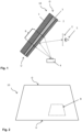
- the projection arrangement according to the invention for a head-up display comprises at least one composite pane with an electrically conductive coating and a projector.
- the projector illuminates an area of the windshield where the radiation is reflected towards the viewer (driver), creating a virtual image that the viewer sees behind the windshield as seen from behind.
- the area of the windshield that can be irradiated by the projector is referred to as the HUD area.
- the beam direction of the projector can typically be varied using mirrors, particularly vertically, in order to adapt the projection to the viewer's height.
- the area in which the viewer's eyes must be located for a given mirror position is referred to as the eyebox window.
- This eyebox window can be moved vertically by adjusting the mirrors, with the entire area that is accessible as a result (ie the superimposition of all possible eyebox windows) being referred to as the eyebox.
- a viewer located within the eyebox can perceive the virtual image. Of course, this means that the viewer's eyes must be inside the eyebox, not the entire body.
- the composite pane comprises an outer pane and an inner pane, which are connected to one another via a thermoplastic intermediate layer.
- the laminated pane is intended to separate the interior from the outside environment in a window opening, in particular the window opening of a vehicle.
- the inner pane refers to the pane of the laminated pane facing the interior (in particular the vehicle interior).
- the outer pane refers to the pane facing the outside environment.
- the laminated pane is preferably a vehicle windshield (particularly the windshield of a motor vehicle, for example a car or truck).
- the laminated pane has an upper edge and a lower edge as well as two side edges running in between.
- the top edge designates that edge which is intended to point upwards in the installation position. With lower edge becomes that edge referred to, which is intended to point downwards in the installed position.
- the upper edge is often referred to as the roof edge and the lower edge as the engine edge.
- the outer pane and the inner pane each have an outside and an inside surface and a circumferential side edge running in between.
- the outside surface designates that main surface which is intended to face the external environment in the installed position.
- the interior-side surface designates that main surface which is intended to face the interior in the installed position.
- the interior surface of the outer pane and the outside surface of the inner pane face each other and are connected to one another by the thermoplastic intermediate layer.
- the laminated pane has an electrically conductive coating, in particular a transparent, electrically conductive coating.
- the electrically conductive coating is preferably applied to one of the surfaces of the two panes facing the intermediate layer, ie the interior surface of the outer pane or the outside surface of the inner pane.
- the electrically conductive coating can also be arranged within the thermoplastic intermediate layer, for example applied to a carrier film which is arranged between two thermoplastic connecting films.
- the conductive coating can be provided, for example, as an IR-reflecting sun protection coating or also as a heatable coating which is electrically contacted and heats up when current flows through it.
- a transparent coating is understood to mean a coating which has an average transmission in the visible spectral range of at least 70%, preferably at least 80%, which means that it does not significantly restrict the view through the pane. At least 80% of the pane surface is preferably provided with the coating according to the invention.
- the coating is applied to the entire surface of the pane surface with the exception of a peripheral edge area and optionally local areas which, as communication, sensor or camera windows, are intended to ensure the transmission of electromagnetic radiation through the composite pane and are therefore not provided with the coating.
- the surrounding uncoated edge area has a width of up to 20 cm, for example. It prevents the coating from coming into direct contact with the surrounding atmosphere, so that the coating on the inside of the laminated pane is protected against corrosion and damage.
- the electrically conductive coating is a layer stack or a layer sequence, comprising one or more electrically conductive, in particular metal-containing layers, each electrically conductive layer being arranged between two dielectric layers or layer sequence.
- the coating is therefore a thin-film stack with n electrically conductive layers and ( n +1) dielectric layers or layer sequences, where n is a natural number and where a conductive layer and a dielectric layer or layer sequence alternate on a lower dielectric layer or layer sequence follows.
- Such coatings are known as sun protection coatings and heatable coatings, with the electrically conductive layers typically being based on silver.
- the electrically conductive coating according to the invention is set in such a way, in particular by the choice of materials and thicknesses of the individual layers and the structure of the dielectric layer sequences, that in the spectral range from 400 nm to 650 nm, preferably in the spectral range from 400 nm to 750 nm, only a single local Reflection maximum for p-polarized radiation occurs.
- This reflection maximum for p-polarized radiation is located in particular in the spectral range from 510 nm to 550 nm.
- this local reflection maximum represents the highest reflection value in the spectral range from 400 nm to 650 nm, i.e. in the spectral range from 400 nm to 650 nm there is no degree of reflection for p-polarized radiation which is higher than the degree of reflection of the local maximum .
- the inventors recognized that such an electrically conductive coating efficiently reflects the p-polarized radiation components and that the laminated pane also has a relatively neutral coloring in terms of transmission and reflection.
- the coating set according to the invention it is possible in particular to freely select the p-polarized radiation component according to the requirements in the individual case, with the coloring always remaining relatively neutral.
- the p-polarized radiation components can be selected in the individual case in such a way that an advantageous overall intensity is achieved.
- the invention can therefore be used flexibly for different HUD systems, which is a great advantage.
- the reflection behavior of the laminated pane which is essentially determined by the electrically conductive coating, is decisive for the properties of the projection arrangement.
- the reflection spectrum is at that with the electrically conductive coating provided laminated pane measured.
- the reflection properties described here for p- or s-polarized radiation do not relate to the insulated electrically conductive coating, but to the composite pane with the electrically conductive coating.
- the degree of reflection describes the proportion of the total radiated radiation that is reflected. It is given in % (relative to 100% incident radiation) or as a unitless number from 0 to 1 (normalized to the incident radiation). Plotted as a function of the wavelength, it forms the reflection spectrum.
- the difference between the reflectance for p-polarized radiation, which occurs at the local reflection maximum in the spectral range from 400 nm to 6500 nm, and the minimum reflectance for p-polarized radiation occurring in the spectral range from 400 nm to 650 nm, is in an advantageous embodiment at most 10%, preferably at most 8%.
- the reflection curve is then relatively flat, which is advantageous with regard to the most true-to-color representation of the projector image.
- the percentages indicate the absolute difference in the degree of reflection (relative to 100% incident radiation).
- the reflection spectrum for s-polarized radiation should also be as flat as possible, i.e. it should not have any pronounced maxima and minima, particularly in the spectral range of 450 nm and 600 nm. If the reflection spectra for both polarization directions are sufficiently flat, the relative proportions of s- polarized and p-polarized radiation can be chosen freely without this being accompanied by an undesirable color shift. In an advantageous embodiment, the degree of reflection for s-polarized radiation is essentially constant in the spectral range from 450 nm to 600 nm.
- the percentages indicate the absolute difference in the degree of reflection (relative to 100% incident radiation).
- the projector is arranged on the interior side of the laminated pane and irradiates the laminated pane via the interior-side surface of the inner pane. It is aimed at the HUD area and illuminates it to create the HUD projection.
- the proportion of p-polarized radiation in the total radiation of the projector is from 20% to 80%.
- the proportion of p-polarized radiation is at least 50%, ie from 50% to 80%, which ensures in particular that a driver with polarization-selective sunglasses can perceive a high-intensity image.
- the specification of the direction of polarization refers to the plane of incidence of the radiation on the laminated pane.
- P-polarized radiation is radiation whose electric field oscillates in the plane of incidence.
- S-polarized radiation is radiation whose electric field oscillates perpendicular to the plane of incidence.
- the plane of incidence is spanned by the incidence vector and the surface normal of the composite pane in the geometric center of the HUD area.
- the radiation from the projector preferably strikes the laminated pane at an angle of incidence of 50° to 80°, in particular 60° to 70°, typically around 65°, as is usual with HUD projection arrangements.
- the angle of incidence is the angle between the incidence vector of the projector radiation and the surface normal at the geometric center of the HUD area.
- the electrically conductive coating according to the invention has at least two functional, electrically conductive layers, particularly preferably at least three electrically conductive layers, very particularly preferably at least four electrically conductive layers, in particular precisely four electrically conductive layers. Due to the high number of conductive layers, sufficient degrees of freedom are available to optimize the coating in terms of transmission and reflection behavior and coloring.
- the electrical conductivity of the coating is caused by the functional, electrically conductive layers. By dividing the entire conductive material into several layers that are separate from one another, these can each be made thinner, which increases the transparency of the coating.
- Each electrically conductive layer contains preferably at least one metal or a metal alloy, for example silver, aluminum, copper or gold, and is particularly preferably formed on the basis of the metal or the metal alloy, i.e. consists essentially of the metal or the metal alloy apart from any doping or impurities. Silver or an alloy containing silver is preferably used.
- the electrically conductive layer contains at least 90% by weight silver, preferably at least 99% by weight silver, particularly preferably at least 99.9% by weight silver.
- Each electrically conductive layer preferably has a layer thickness of 3 nm to 20 nm, particularly preferably 5 nm to 15 nm.
- the total layer thickness of all electrically conductive layers is preferably from 20 nm to 50 nm, particularly preferably from 30 nm to 40 nm.
- dielectric layers or layer sequences are arranged between the electrically conductive layers and below the bottom conductive layer and above the top conductive layer.
- Each dielectric layer or layer sequence has at least one antireflection coating.
- the anti-reflective layers reduce the reflection of visible light and thus increase the transparency of the coated pane.
- the anti-reflective coatings contain, for example, silicon nitride (SiN), silicon-metal mixed nitrides such as silicon zirconium nitride (SiZrN), aluminum nitride (AlN) or tin oxide (SnO).
- the antireflection coatings can also have doping.
- the layer thickness of the individual antireflection coatings is preferably from 10 nm to 70 nm.
- the antireflection coatings can in turn be subdivided into at least two partial layers, in particular into a dielectric layer with a refractive index of less than 2.1 and an optically high-index layer with a refractive index of greater than or equal to 2.1.
- At least one anti-reflection layer arranged between two electrically conductive layers is preferably subdivided in this way, particularly preferably each anti-reflection layer arranged between two electrically conductive layers. The subdivision of the anti-reflection layer leads to a lower surface resistance of the electrically conductive coating with high transmission and high color neutrality at the same time.
- the sequence of the two partial layers can in principle be selected in any order, with the optically high-index layer preferably being arranged above the dielectric layer, which is particularly advantageous with regard to the sheet resistance.
- the thickness of the optically high-index layer is preferably from 10% to 99%, particularly preferably from 25% to 75% of the total thickness of the antireflection layer.
- the optically high-index layer with a refractive index greater than or equal to 2.1 contains, for example, MnO, WOs, Nb 2 O 5 , Bi 2 O 3 , TiO 2 , Zr 3 N 4 and/or AlN, preferably a silicon-metal mixed nitride, for example Silicon-aluminum mixed nitride, silicon-hafnium mixed nitride or silicon-titanium mixed nitride, particularly preferably silicon-zirconium mixed nitride (SiZrN). This is particularly advantageous with regard to the surface resistance of the electrically conductive coating.
- the silicon-zirconium mixed nitride preferably has doping.
- the layer of an optically high-index material can contain, for example, an aluminum-doped silicon-zirconium mixed nitride. The proportion of zirconium is preferably between 15 and 45% by weight, particularly preferably between 15 and 30% by weight.
- the dielectric layer with a refractive index of less than 2.1 preferably has a refractive index n between 1.6 and 2.1, particularly preferably between 1.9 and 2.1.
- the dielectric layer preferably contains at least one oxide, for example tin oxide, and/or a nitride, particularly preferably silicon nitride.
- each antireflection layer arranged between two electrically conductive layers is divided into a dielectric layer with a refractive index of less than 2.1 and an optically high-index layer with a refractive index of greater than or equal to 2.1.
- the thickness of each anti-reflective layer arranged between two electrically conductive layers is from 15 nm to 60 nm.
- the anti-reflective layers above the uppermost electrically conductive layer and below the lowermost electrically conductive layer can also be subdivided, but are preferably designed as individual layers and each have a thickness of 10 nm to 25 nm.
- one or more dielectric layer sequences has a first adaptation layer, preferably each dielectric layer sequence, which is arranged below an electrically conductive layer.
- the first adaptation layer is preferably arranged above the antireflection layer.
- one or more dielectric layer sequences has a smoothing layer, preferably each dielectric layer sequence that is arranged between two electrically conductive layers.
- the smoothing layer is arranged below one of the first adjustment layers, preferably between the Anti-reflective layer and the first matching layer.
- the smoothing layer is particularly preferably in direct contact with the first adaptation layer.
- the smoothing layer brings about an optimization, in particular smoothing, of the surface for an electrically conductive layer subsequently applied on top.
- An electrically conductive layer deposited on a smoother surface has a higher degree of transmission with a simultaneously lower surface resistance.
- the layer thickness of a smoothing layer is preferably from 3 nm to 20 nm, particularly preferably from 4 nm to 12 nm.
- the smoothing layer preferably has a refractive index of less than 2.2.
- the smoothing layer preferably contains at least one non-crystalline oxide.
- the oxide can be amorphous or partially amorphous (and thus partially crystalline), but is not fully crystalline.
- the non-crystalline smoothing layer has a low level of roughness and thus forms an advantageously smooth surface for the layers to be applied above the smoothing layer.
- the non-crystalline smoothing layer also brings about an improved surface structure of the layer deposited directly above the smoothing layer, which is preferably the first adaptation layer.
- the smoothing layer may contain at least one oxide of one or more of tin, silicon, titanium, zirconium, hafnium, zinc, gallium and indium.
- the smoothing layer particularly preferably contains a non-crystalline compound oxide.
- the smoothing layer most preferably contains a tin-zinc mixed oxide (ZnSnO).
- the mixed oxide can have doping.
- the smoothing layer can contain, for example, an antimony-doped tin-zinc mixed oxide.
- the mixed oxide preferably has a substoichiometric oxygen content.
- the tin content is preferably between 10 and 40% by weight, particularly preferably between 12 and 35% by weight.
- one or more dielectric layer sequences has a second adaptation layer, preferably each dielectric layer sequence, which is arranged above an electrically conductive layer.
- the second adaptation layer is preferably arranged below the antireflection layer.
- the first and second matching layers act to improve the sheet resistance of the coating.
- the first adaptation layer and/or the second adaptation layer preferably contains zinc oxide ZnO 1- ⁇ with 0 ⁇ 0.01.
- the first matching layer and/or the second matching layer preferably contains dopings.
- the first matching layer and/or the second matching layer may contain aluminum-doped zinc oxide (ZnO:Al), for example.
- the zinc oxide is preferably substoichiometrically deposited with respect to the oxygen to a reaction of to avoid excess oxygen with the silver-containing layer.
- the layer thicknesses of the first matching layer and the second matching layer are preferably from 3 nm to 20 nm, particularly preferably from 4 nm to 12 nm.
- the electrically conductive coating includes one or more blocker layers. At least one blocking layer is preferably assigned to at least one, particularly preferably to each electrically conductive layer.
- the blocking layer is in direct contact with the electrically conductive layer and is arranged directly above or directly below the electrically conductive layer. No further layer is therefore arranged between the electrically conductive layer and the blocking layer.
- a blocking layer can also be arranged directly above and directly below a conductive layer.
- the blocking layer preferably contains niobium, titanium, nickel, chromium and/or alloys thereof, particularly preferably nickel-chromium alloys.
- the layer thickness of the blocking layer is preferably from 0.1 nm to 2 nm, particularly preferably from 0.1 nm to 1 nm.
- a blocking layer directly below the electrically conductive layer is used in particular to stabilize the electrically conductive layer during heat treatment and improves the optical quality the electrically conductive coating.
- a blocking layer immediately above the electrically conductive layer prevents contact of the sensitive electrically conductive layer with the oxidizing reactive atmosphere during the deposition of the following layer by reactive sputtering, for example the second conforming layer.
- first layer is arranged above a second layer, this means within the meaning of the invention that the first layer is arranged further away from the substrate on which the coating is applied than the second layer. If a first layer is arranged below a second layer, this means within the meaning of the invention that the second layer is arranged further away from the substrate than the first layer. If a first layer is arranged above or below a second layer, this does not necessarily mean within the meaning of the invention that the first and the second layer are in direct contact with one another. One or more further layers can be arranged between the first and the second layer unless this is explicitly excluded.
- the values given for the refractive indices are measured at a wavelength of 550 nm.
- the electrically conductive coating with the reflection characteristics according to the invention can basically be realized in different ways, preferably using the layers described above, so that the invention is not limited to a specific layer sequence.
- a particularly preferred embodiment of the coating is presented below, with which particularly good results are achieved, in particular with a typical angle of incidence of the radiation of approximately 65°.
- the conductive coating has at least four, in particular exactly four, electrically conductive layers.
- Each electrically conductive layer preferably has a layer thickness of 3 nm to 20 nm, particularly preferably 5 nm to 15 nm.
- the total layer thickness of all electrically conductive layers is preferably from 20 nm to 50 nm, particularly preferably from 30 nm to 40 nm.
- the anti-reflection layer between the second and the third conductive layer is made significantly thicker (preferably from 45 nm to 55 nm) than the anti-reflection layers between the first and second conductive layer and between the third and fourth conductive layer (preferably from 15 nm to 35 nm, in particular one of the two anti-reflection coatings having a thickness of 15 nm to 25 nm and the other a thickness of 25 nm to 35 nm).
- the antireflection layer between the first and the second electrically conductive layer particularly preferably has a thickness of 25 nm to 35 nm.
- the antireflection layer between the second and the third electrically conductive layer particularly preferably has a thickness of 45 nm to 55 nm.
- the antireflection layer between the third and the fourth electrically conductive layer particularly preferably has a thickness of 15 nm to 25 nm.
- All anti-reflective layers that are arranged between two electrically conductive layers are divided, as described above, into a dielectric layer with a refractive index of less than 2.1 (preferably based on silicon nitride) and an optically high-index layer with a refractive index of greater than or equal to 2.1 ( preferably based on a silicon-metal mixed nitride such as silicon zirconium nitride or silicon hafnium nitride).
- the optically high-index layer preferably accounts for from 25% to 75% of the total thickness of the antireflection coatings.
- the anti-reflective layers below the bottom conductive layer and above the top conductive layer are formed as individual layers with a layer thickness of 10 nm to 25 nm.
- the anti-reflective layer below the bottom conductive layer is based on silicon nitride and is preferably formed with a thickness of 15 nm to 25 nm and the Anti-reflective layer above the top conductive layer based on a silicon-metal mixed nitride such as silicon zirconium nitride or silicon hafnium nitride with a thickness of 8 nm to 18 nm.
- the particularly preferred embodiment of the coating also contains matching layers and smoothing layers, as well as optionally blocking layers, as described above.
- a layer is formed on the basis of a material, the majority of the layer consists of this material in addition to any impurities or dopings.
- undesirable secondary images can occur, which are perceived in particular by drivers without polarization-selective sunglasses.
- the s-polarized radiation components are initially reflected on the surface of the inner pane facing away from the intermediate layer on the interior side.
- the non-reflected partial beam runs through the laminated pane and is reflected again on the outside surface of the outer pane facing away from the intermediate layer.
- two configurations are proposed within the scope of the invention.
- thermoplastic intermediate layer is used as the thermoplastic intermediate layer.
- the thickness of the intermediate layer is variable in the vertical course between the lower edge and the upper edge of the laminated pane, at least in the HUD area, in particular increasing monotonically. However, the thickness can also change over the entire vertical course, in particular increasing monotonically starting from the lower edge to the upper edge.
- vertical gradient is the gradient between bottom edge and top edge denoted by direction of extension substantially perpendicular to said edges.
- the angle between the two surfaces of the interlayer is called the wedge angle. If the wedge angle is not constant, the tangents to the surfaces must be used to measure it at one point.
- the wedge angle is preferably from 0.2 mrad to 1 mrad, particularly preferably from 0.3 mrad to 0.7 mrad, very particularly preferably from 0.4 mrad to 0.5 mrad. Due to the wedge angle of the intermediate layer, the outer pane and the inner pane are not parallel to one another and precisely enclose that wedge angle. In the case of parallel pane surfaces, the image (generated by the reflection of the s-polarized portion of radiation on the interior surface of the inner pane) and the ghost image (generated by the reflection of the s-polarized portion of radiation on the outside surface of the outer pane) would appear offset to one another, which is disturbing for the viewer . Due to the wedge angle, the ghost image is essentially spatially superimposed with the image, so that the viewer only perceives a single image or the distance between the image and the ghost image is at least reduced.
- the intermediate layer is wedge-shaped or wedge-like, at least in the HUD area, with the wedge angle being selected appropriately in order to superimpose the projection images that are caused by the reflections on the interior surface of the inner pane and on the outside surface of the outer pane, or at least superimpose them reduce distance from each other.
- the wedge angle of the interlayer may be constant vertically, resulting in a linear change in thickness of the interlayer, typically increasing in thickness from bottom to top.
- the indication of direction "from bottom to top” refers to the direction from the lower edge to the upper edge, i.e. the vertical course.
- there can also be more complex thickness profiles in which the wedge angle changes from bottom to top that is to say is location-dependent in the vertical course), linear or non-linear.
- wedge-like inner panes or outer panes can also be used instead of a wedge foil in the intermediate layer in order to angle the reflection surfaces towards one another.
- an antireflection coating is applied to the interior surface of the inner pane.
- the HUD image which would be generated by reflection of the interior-side surface of the inner pane, is suppressed.
- the (s-polarized) HUD image is only affected by the reflection from the outside Generated surface of the outer pane and there is no or only a noticeably reduced intensity ghost image.
- the antireflection coating is preferably a layer sequence with an alternating high and low refractive index, which leads to a reduction in reflection at the coated surface due to interference effects.
- Such antireflection coatings are known per se.
- the presence of the anti-reflection coating affects the reflective behavior of the laminated pane.
- the anti-reflection coating is preferably adjusted, in particular through a suitable choice of materials and layer thicknesses, so that the composite pane with the electrically conductive coating and the anti-reflection coating meets the requirements of the invention for the reflection behavior, i.e. in particular in the spectral range from 400 nm to 650 nm only a single local reflection maximum for p-polarized radiation, which is in the range of 510 nm to 550 nm.
- the preferred configurations described above apply accordingly.
- the antireflection coating can be formed in various ways, and the invention is not limited to a specific layer sequence.
- the anti-reflection coating preferably comprises, starting from the substrate, a high-index layer with a refractive index greater than 1.8, above that a low-index layer with a refractive index less than 1.8, above that another high-index layer with a refractive index greater than 1.8 and above that another low-index layer with a Refractive index less than 1.8.
- the intermediate layer can also be wedge-shaped, for example in order to overlay the s-polarized image (from the reflection on the outside surface of the outer pane) and the p-polarized image (from the reflection on the conductive coating) with one another and thus reducing the occurrence of layer ghosting for drivers without polarization selective sunglasses.
- the intermediate layer is then wedge-shaped or wedge-like, at least in the HUD area, with the wedge angle being selected appropriately in order to superimpose the projection images, which are caused by the reflections on the electrically conductive coating and on the outside surface of the outer pane, or at least superimpose them reduce distance from each other.
- the distance between the main image and the ghost image is smaller for the layer ghost image than for the ghost image generated by the pane surfaces, making the layer ghost image less noticeable. It is therefore possible to use an intermediate layer whose thickness is essentially constant in the vertical course between the upper edge and the lower edge. Such a non-wedge shaped interlayer is preferred because it is significantly less expensive, allowing the laminated pane to be manufactured more economically. The conspicuousness of the layer ghost image is within acceptable limits for typical laminated panes, so that no measures have to be taken to avoid it.
- the outer pane and the inner pane are preferably made of glass, in particular of soda-lime glass, which is common for window panes.
- the panes can also be made of other types of glass (for example borosilicate glass, quartz glass, aluminosilicate glass) or transparent plastics (for example polymethyl methacrylate or polycarbonate).
- the thickness of the outer pane and the inner pane can vary widely. Preferably discs with a thickness in the range of 0.8 mm to 5 mm, preferably from 1.4 mm to 2.5 mm, for example those with the standard thicknesses of 1.6 mm or 2.1 mm.
- the outer pane, the inner pane and the thermoplastic intermediate layer can be clear and colorless, but also tinted or colored. In a preferred embodiment, the total transmission through the laminated glass is greater than 70%.
- the term total transmission refers to the procedure specified by ECE-R 43, Appendix 3, Section 9.1 for testing the light transmittance of motor vehicle windows.
- the outer pane and the inner panes can be unprestressed, partially prestressed or prestressed independently of one another. If at least one of the panes is to have a prestress, this can be a thermal or chemical prestress.
- the laminated pane is preferably curved in one or more spatial directions, as is customary for motor vehicle panes, with typical radii of curvature being in the range from about 10 cm to about 40 m.
- the composite pane can also be flat, for example if it is intended as a pane for buses, trains or tractors.
- the thermoplastic intermediate layer contains at least one thermoplastic polymer, preferably ethylene vinyl acetate (EVA), polyvinyl butyral (PVB) or polyurethane (PU) or mixtures or copolymers or derivatives thereof, particularly preferably PVB.
- the intermediate layer is typically formed from a thermoplastic film.
- the thickness of the intermediate layer is preferably from 0.2 mm to 2 mm, particularly preferably from 0.3 mm to 1 mm. If a wedge-shaped interlayer is used, the thickness is determined at the thinnest point, typically at the lower edge of the laminated pane.
- the laminated pane can be manufactured by methods known per se.
- the outer pane and the inner pane are laminated to one another via the intermediate layer, for example by autoclave methods, vacuum bag methods, vacuum ring methods, calendering methods, vacuum laminators or combinations thereof.
- the outer pane and inner pane are usually connected under the action of heat, vacuum and/or pressure.
- the electrically conductive coating is preferably applied to the inner pane by physical vapor deposition (PVD), particularly preferably by cathode atomization ("sputtering"), very particularly preferably by magnetic field assisted cathode sputtering.
- PVD physical vapor deposition
- sputtering cathode atomization
- magnetic field assisted cathode sputtering very particularly preferably by magnetic field assisted cathode sputtering.
- the coating or coatings are preferably applied to the panes prior to lamination. Instead of applying the electrically conductive coating to a pane surface, it can in principle also be provided on a carrier film that is arranged in the intermediate layer.
- the outer pane and the inner pane are preferably subjected to a bending process before lamination and preferably after any coating processes.
- the outer pane and the inner pane are preferably bent congruently together (i.e. at the same time and using the same tool), because the shape of the panes is then optimally matched to one another for the lamination that takes place later.
- Typical temperatures for glass bending processes are 500°C to 700°C, for example.
- the invention also includes the use of a composite pane designed according to the invention as a projection surface of a projection arrangement for a head-up display, with a projector being aimed at the HUD area whose radiation has a p-polarized proportion of 20% to 80%.
- the preferred configurations described above apply correspondingly to the use.
- the projection arrangement is preferably used as a HUD in a motor vehicle, in particular a passenger car or truck.
- the invention is explained in more detail below with reference to a drawing and exemplary embodiments.
- the drawing is a schematic representation and not to scale. The drawing does not limit the invention in any way.
- the projection arrangement comprises a composite pane 10, in particular the windshield of a passenger car.
- the projection arrangement also includes a projector 4 which is directed onto an area B of the laminated pane 10 .
- the area B which is usually referred to as the HUD area
- images can be generated by the projector 4, which are perceived by a viewer 5 (vehicle driver) as virtual images on the side of the laminated pane 10 facing away from him when his eyes located within the so-called eyebox E.
- the laminated pane 10 is made up of an outer pane 1 and an inner pane 2 which are connected to one another via a thermoplastic intermediate layer 3 . Its lower edge U is arranged downwards towards the engine of the passenger car, its upper edge O upwards towards the roof.
- the laminated pane 10 also includes an electrically conductive coating, not shown, which is provided, for example, as an IR-reflecting coating or as a heatable coating. In the installed position, the outer pane 1 faces the outside environment, and the inner pane 2 faces the vehicle interior.
- the radiation from the projector 4 includes a mixture of s-polarized and p-polarized components. Since the projector 4 irradiates the laminated pane 10 at an angle of incidence of approximately 65°, which is close to Brewster's angle, the surfaces of the laminated pane 10 predominantly reflect the s-polarized radiation components.
- the electrically conductive coating according to the invention is optimized for the reflection of the p-polarized radiation components.
- a viewer 5 with polarization-selective sunglasses that only allows p-polarized radiation to pass can therefore perceive the HUD projection. This is not the case with conventional projection arrangements, which only work with s-polarized radiation.
- a viewer 5 without sunglasses sees the sum of s-polarized and p-polarized radiation, so that the intensity of the HUD projection is not reduced for him.
- FIG 2 12 shows a plan view of the laminated pane 10 from FIG figure 1 . You can see the top edge O, the bottom edge U and the HUD area B.
- the outer pane 1 has an outside surface I, which faces the outside environment in the installed position, and an interior surface II, which faces the interior in the installed position.
- the inner pane 2 has an outside surface III, which faces the outside environment in the installed position, and an interior-side surface IV, which faces the interior in the installed position.
- the outer pane 1 and the inner pane 2 consist, for example, of soda-lime glass.
- the outer pane 1 has a thickness of 2.1 mm, for example, and the inner pane 2 has a thickness of 1.6 mm.
- the intermediate layer 3 is formed, for example, from a PVB film with a thickness of 0.76 mm.
- the outside surface III of the inner pane 2 is provided with the electrically conductive coating 20 according to the invention.
- the s-polarized radiation components of the projector 4 are each partially reflected on the interior surface of the inner pane 1 (primary reflection) and on the outside surface of the outer pane 1 (secondary reflection). There is no appreciable refractive index transition at the interfaces between the panes 1, 2 and the intermediate layer 3, so that they do not form any reflection surfaces.
- the two reflections lead to two offset HUD projections (a main image and a so-called ghost image), which is disturbing for the viewer 5.
- the intermediate layer 3 is designed in the manner of a wedge. The thickness of the intermediate layer 3 increases continuously in the vertical course from the lower edge U to the upper edge O.
- the increase in thickness is shown linearly in the figure for the sake of simplicity, but it can also have more complex profiles.
- the wedge angle ⁇ describes the angle between the two surfaces of the intermediate layer and is approximately 0.5 mrad, for example. Due to the wedge-like intermediate layer, which leads to an angled arrangement of the two reflection surfaces I, IV, the main image and ghost image are ideally superimposed, but at least their distance is reduced.
- FIG. 4 shows a further embodiment of a laminated pane 10 designed according to the invention.
- the outer pane 1 and the inner pane 2 are designed in exactly the same way as in FIG figure 3 .
- the electrically conductive coating 20 is also applied to the outside surface III of the inner pane 2 here.
- the intermediate layer 3 is not wedge-shaped here, but in the form of a standard film with a constant thickness of 0.76 mm, for example.
- the ghost image problem is solved in a different way here: the interior-side surface IV of the inner pane 2 is provided with an anti-reflection coating 30 . This suppresses the reflection on the surface IV, so that the s-polarized radiation components are only reflected on the outside surface I of the outer pane.
- the antireflection coating 30 according to the invention is set in such a way that it does not significantly shift the reflection spectrum of the laminated pane 10 for p-polarized radiation, so that the properties according to the invention with regard to p-polarized radiation are retained.
- an observer 5 without polarization-selective sunglasses will perceive a so-called layer ghost image (p-polarized) in addition to the HUD projection (s-polarized) generated on the outside surface I, which is generated by the electrically conductive coating 20 .
- layer ghost image p-polarized
- HUD projection s-polarized
- the distance between the two reflection planes is sufficiently small for normal pane thicknesses that the layer ghost image is within acceptable limits.
- the distance between the two projections could be reduced even further if the electrically conductive coating 20 were applied to the interior surface of the outer pane II and/or a thinner outer pane 1 and/or a thinner intermediate layer 3 were used.
- figure 5 shows the layer sequence of an electrically conductive coating 20 according to the invention.
- the coating 20 contains four electrically conductive layers 21 (21.1, 21.2, 21.3, 21.4).
- Each electrically conductive layer 21 is arranged between two of a total of five anti-reflective layers 22 (22.1, 22.2, 22.3, 22.4, 22.5).
- the antireflection layers 22.2, 22.3, 22.4, which are arranged between two electrically conductive layers 21, are each divided into a dielectric layer 22a (22a.2, 22a.3, 22a.4) and an optically high-index layer 22b (22b.2, 22b.3, 22b.4).
- the coating 20 also includes three smoothing layers 23 (23.2, 23.3, 23.4), four first matching layers 24 (24.1, 24.2, 24.3, 24.4), four second matching layers 25 (25.2, 25.3, 25.4, 25.5) and four blocking layers 26 (26.1, 26.2, 26.3, 26.4).
- the sequence of layers can be seen schematically in the figure.
- the layer sequence of a laminated pane 10 with the coating 20 on the outside surface III of the inner pane 2 is also shown in Table 1 (example), together with the materials and layer thicknesses of the individual layers.
- Table 1 also shows the layer sequence of an electrically conductive coating as is currently already in use (comparative example). It can be seen that the reflection properties of the coating 20 according to the invention were achieved by suitable optimization of the layer thicknesses of the individual layers.
- FIG. 6 shows the layer sequence of an antireflection coating 30 according to the invention, comprising two high-index layers 31 (31.1, 31.2) and two low-index layers 32 (32.1, 32.2).
- the sequence of layers can be seen schematically in the figure.
- the layer sequence of a composite pane 10 with the electrically conductive coating 20 on the outside surface III of the inner pane 2 and the anti-reflection coating 30 on the interior surface IV of the inner pane 2 is also shown in Table 2, together with the materials and layer thicknesses of the individual layers.
- Table 1 material Reference sign layer thickness Example comparative example Glass 1 2.1mm 2.1mm PVB 3 0.76mm 0.76mm SiZrN 20 22.5 12.3nm 25.2nm ZnO 25.5 10.0nm 10.0nm NiCr 26.4 0.2nm 0.2nm Ag 21.4 5.3nm 14.1nm ZnO 24.4 10.0nm 10.0nm SnZnO:Sb 23.4 7.0nm 7.0nm SiZrN 22b.4 22.4 15.0 22.9nm SiN 22a.4 5.2nm 29.8nm ZnO 25.4 10.0nm 10.0nm NiCr 26.3 0.2nm 0.2nm Ag 21.3 9.6nm 14.2nm ZnO 24.3 10.0nm 10.0nm SnZnO:Sb 23.3 7.0nm 7.0nm SiZrN 22b.3 22.3 15.0nm 20.1nm SiN 22a.3 35.1nm 29.6nm ZnO 25.3 10.0nm 10.0
- FIG. 7 shows the reflection spectrum of a laminated pane 10 with a conventional conductive coating 20 according to the comparative example and a conductive coating 20 according to the invention according to the example (cf. Table 1) for p-polarized radiation (part a) and for s-polarized radiation (part b).
- the spectra were measured on the interior side at an angle of incidence of 65°, i.e. simulating the reflection behavior for the HUD projector.
- the conventional coating according to the comparative example has two local reflection maxima in the spectral range from 400 nm to 650 nm for p-polarized radiation: at 476 nm and at 600 nm
- the minimum degree of reflection that occurs for p-polarized radiation in the spectral range from 400 nm to 650 nm is significantly more than 10%.
- the coating according to the invention according to the example has only a single local reflection maximum in the spectral range from 400 nm to 650 nm for p-polarized radiation.
- the local reflection maximum is at 516 nm, i.e. in the green spectral range to which the human eye is particularly sensitive.
- the difference between the degree of reflection of the local reflection maximum and the minimum occurring degree of reflection for p-polarized radiation in the spectral range from 400 nm to 650 nm is only 6.7%.
- the reflection spectrum of the coating according to the invention is also significantly flatter for s-polarized radiation than that of the conventional coating in the spectral range from 450 nm to 600 nm.
- the difference between the maximum reflectance that occurs and the mean value is 0.4%, the difference between the minimum that occurs Degree of reflection and the mean value 0.3%.
- a HUD image with a neutral coloring is generated by the configuration of the coating of the example according to the invention.
- the relative proportions of s-polarized and p-polarized radiation can be chosen freely without this being associated with a color shift or other undesirable effects.
- the radiation components can therefore be adjusted according to the requirements in the individual case, without the person skilled in the art being subject to any limits as a result of the coating.
- a ratio can be set so that an optimal intensity of the HUD projection is achieved for drivers with and without polarization-selective sunglasses.
- Table 3 shows the total degree of reflection for different polarization components of the projector radiation, on the one hand for a conventional composite pane (coating 20 as specified in Table 1 under the comparative example, no anti-reflective coating 30), on the other hand for a composite pane according to the invention (coating 20 as specified in Table 1 under the example, Structure with anti-reflective coating 30 as indicated in Table 2). It can be clearly seen that the reflectance for p-polarized radiation (perceived by a viewer with polarization-selective sunglasses) is significantly increased at any given polarization ratio.
Landscapes
- Chemical & Material Sciences (AREA)
- Physics & Mathematics (AREA)
- Engineering & Computer Science (AREA)
- General Physics & Mathematics (AREA)
- Optics & Photonics (AREA)
- Materials Engineering (AREA)
- Organic Chemistry (AREA)
- Chemical Kinetics & Catalysis (AREA)
- General Chemical & Material Sciences (AREA)
- Geochemistry & Mineralogy (AREA)
- Life Sciences & Earth Sciences (AREA)
- Combustion & Propulsion (AREA)
- Inorganic Chemistry (AREA)
- Transportation (AREA)
- Mechanical Engineering (AREA)
- Instrument Panels (AREA)
- Laminated Bodies (AREA)
- Surface Treatment Of Optical Elements (AREA)
- Polarising Elements (AREA)
- Joining Of Glass To Other Materials (AREA)
Applications Claiming Priority (2)
| Application Number | Priority Date | Filing Date | Title |
|---|---|---|---|
| EP18163269 | 2018-03-22 | ||
| PCT/EP2019/052574 WO2019179683A1 (de) | 2018-03-22 | 2019-02-04 | Projektionsanordnung für ein head-up-display (hud) mit p-polarisierten strahlungsanteilen |
Publications (2)
| Publication Number | Publication Date |
|---|---|
| EP3769143A1 EP3769143A1 (de) | 2021-01-27 |
| EP3769143B1 true EP3769143B1 (de) | 2023-06-07 |
Family
ID=61800323
Family Applications (1)
| Application Number | Title | Priority Date | Filing Date |
|---|---|---|---|
| EP19702098.5A Active EP3769143B1 (de) | 2018-03-22 | 2019-02-04 | Projektionsanordnung für ein head-up-display (hud) mit p-polarisierten strahlungsanteilen |
Country Status (11)
| Country | Link |
|---|---|
| US (1) | US11526009B2 (es) |
| EP (1) | EP3769143B1 (es) |
| JP (1) | JP7104788B2 (es) |
| KR (1) | KR102464962B1 (es) |
| CN (1) | CN110520782B (es) |
| BR (1) | BR112020007393A2 (es) |
| MA (1) | MA52064A (es) |
| MX (1) | MX2020009808A (es) |
| PE (1) | PE20200980A1 (es) |
| RU (1) | RU2748645C1 (es) |
| WO (1) | WO2019179683A1 (es) |
Families Citing this family (26)
| Publication number | Priority date | Publication date | Assignee | Title |
|---|---|---|---|---|
| EP3822076A1 (de) * | 2019-11-15 | 2021-05-19 | Saint-Gobain Glass France | Verbundscheibe für ein head-up-display mit einer keilförmigen glasscheibe und einer keilförmigen zwischenschicht |
| CN114829989A (zh) * | 2019-11-28 | 2022-07-29 | 法国圣戈班玻璃厂 | 用于平视显示器(HUD)的具有p偏振辐射的投影装置 |
| WO2021209201A1 (de) | 2020-04-16 | 2021-10-21 | Saint-Gobain Glass France | Projektionsanordnung für ein head-up-display (hud) mit p-polarisierter strahlung |
| WO2022017707A1 (de) | 2020-07-20 | 2022-01-27 | Saint-Gobain Glass France | Projektionsanordnung für ein head-up-display (hud) mit p-polarisierter strahlung |
| WO2022022886A1 (de) | 2020-07-29 | 2022-02-03 | Saint-Gobain Glass France | Projektionsanordnung für ein head-up-display (hud) mit p-polarisierter strahlung |
| WO2022029689A1 (en) * | 2020-08-05 | 2022-02-10 | Agp America S.A. | Laminate with large area hud and solar properties |
| DE202020105642U1 (de) | 2020-10-01 | 2022-01-07 | Saint-Gobain Sekurit Deutschland Gmbh & Co. Kg | Verbundscheibe |
| US20230405975A1 (en) | 2020-10-01 | 2023-12-21 | Saint-Gobain Glass France | Composite pane |
| EP4228892A1 (de) | 2020-10-19 | 2023-08-23 | Saint-Gobain Glass France | Projektionsanordnung für ein head-up-display (hud) mit p-polarisierter strahlung |
| US20240009967A1 (en) | 2021-01-21 | 2024-01-11 | Saint-Gobain Glass France | Projection assembly for a head-up display (hud) with p-polarized radiation |
| CN113031276B (zh) | 2021-03-29 | 2022-05-10 | 福耀玻璃工业集团股份有限公司 | 一种抬头显示系统 |
| WO2022218699A1 (de) | 2021-04-12 | 2022-10-20 | Saint-Gobain Glass France | Projektionsanordnung mit einer verbundscheibe |
| CN113238378B (zh) * | 2021-04-14 | 2022-07-19 | 福耀玻璃工业集团股份有限公司 | 一种抬头显示系统 |
| WO2023031180A1 (de) | 2021-09-03 | 2023-03-09 | Saint-Gobain Glass France | Verbundscheibe für ein head-up-display |
| WO2023052228A1 (de) | 2021-09-29 | 2023-04-06 | Saint-Gobain Glass France | Projektionsanordnung für ein head-up-display mit p-polarisierter strahlung |
| CN113858730B (zh) * | 2021-10-08 | 2023-04-28 | 福耀玻璃工业集团股份有限公司 | 夹层玻璃及抬头显示系统 |
| CN113878953A (zh) * | 2021-10-08 | 2022-01-04 | 福耀玻璃工业集团股份有限公司 | 夹层玻璃及抬头显示系统 |
| KR20240066271A (ko) * | 2021-10-08 | 2024-05-14 | 푸야오 글라스 인더스트리 그룹 컴퍼니 리미티드 | 접합 유리 및 헤드업 디스플레이 시스템 |
| WO2023083578A1 (de) | 2021-11-12 | 2023-05-19 | Saint-Gobain Glass France | Projektionsanordnung umfassend eine verbundscheibe |
| WO2023083579A2 (de) | 2021-11-12 | 2023-05-19 | Saint-Gobain Glass France | Projektionsanordnung umfassend eine verbundscheibe |
| WO2023099166A1 (de) | 2021-11-30 | 2023-06-08 | Saint-Gobain Glass France | Verbundscheibe mit einer elektrisch leitfähigen beschichtung und lokaler antireflexbeschichtung |
| WO2023104631A1 (de) | 2021-12-07 | 2023-06-15 | Saint-Gobain Glass France | Verbundscheibe für ein head-up-display system mit p-polarisierter strahlung |
| WO2023104634A1 (de) | 2021-12-07 | 2023-06-15 | Saint-Gobain Glass France | Verbundscheibe für ein head-up-display system mit p-polarisierter strahlung |
| CN117157571A (zh) | 2022-01-25 | 2023-12-01 | 法国圣戈班玻璃厂 | 用于具有p偏振辐射的平视显示器(HUD)的投影装置 |
| CN115032796A (zh) * | 2022-06-30 | 2022-09-09 | 福耀玻璃工业集团股份有限公司 | 抬头显示玻璃及抬头显示系统 |
| JP2024006490A (ja) * | 2022-07-01 | 2024-01-17 | 日本板硝子株式会社 | 自動車用合わせガラス |
Family Cites Families (24)
| Publication number | Priority date | Publication date | Assignee | Title |
|---|---|---|---|---|
| US6259559B1 (en) * | 1995-03-28 | 2001-07-10 | Central Glass Company, Limited | Glass arrangement including an outside glass plate, a polarization direction changing film and an adhesive layer therebetween, and an inside glass layer |
| US6734396B2 (en) | 2001-09-07 | 2004-05-11 | Centre Luxembourgeois De Recherches Pour Le Verre Et La Ceramique S.A. (C.R.V.C.) | Heatable vehicle window with different voltages in different heatable zones |
| FR2862961B1 (fr) | 2003-11-28 | 2006-02-17 | Saint Gobain | Substrat transparent utilisable alternativement ou cumulativement pour le controle thermique, le blindage electromagnetique et le vitrage chauffant. |
| US20070009714A1 (en) | 2005-05-11 | 2007-01-11 | Lee David J | Polymeric interlayers having a wedge profile |
| US7335421B2 (en) | 2005-07-20 | 2008-02-26 | Ppg Industries Ohio, Inc. | Heatable windshield |
| FR2895522B1 (fr) | 2005-12-23 | 2008-04-11 | Saint Gobain | Substrat transparent comportant un revetement antireflet |
| JP2007223883A (ja) | 2005-12-26 | 2007-09-06 | Asahi Glass Co Ltd | 車両用合せガラス |
| FR2898295B1 (fr) * | 2006-03-10 | 2013-08-09 | Saint Gobain | Substrat transparent antireflet presentant une couleur neutre en reflexion |
| US8451541B2 (en) | 2007-12-07 | 2013-05-28 | Saint-Gobain Glass France | Curved vehicle windshield made from laminated glass |
| US8488246B2 (en) * | 2010-02-28 | 2013-07-16 | Osterhout Group, Inc. | See-through near-eye display glasses including a curved polarizing film in the image source, a partially reflective, partially transmitting optical element and an optically flat film |
| EP2666757A4 (en) * | 2011-01-18 | 2015-07-22 | Asahi Glass Co Ltd | COATED GLASS AND METHOD FOR PRODUCING COATED GLASS |
| PT2803245T (pt) | 2012-01-10 | 2017-05-22 | Saint Gobain | Placa de vidro transparente com revestimento condutor de eletricidade |
| KR101574456B1 (ko) | 2012-01-10 | 2015-12-11 | 쌩-고벵 글래스 프랑스 | 도전성 코팅이 있는 투명 패널 |
| KR102651578B1 (ko) * | 2013-11-27 | 2024-03-25 | 매직 립, 인코포레이티드 | 가상 및 증강 현실 시스템들 및 방법들 |
| CN104044313B (zh) * | 2014-07-01 | 2015-03-25 | 深圳市三鑫精美特玻璃有限公司 | 防刮伤超硬玻璃及其制备方法 |
| DE102014220189B4 (de) | 2014-10-06 | 2023-08-17 | Continental Automotive Technologies GmbH | Head-Up-Display und Verfahren zur Erzeugung eines virtuellen Bilds mittels eines Head-Up-Displays und Verwendung von p-polarisiertem Licht in einem Head-Up-Display |
| CN104267499B (zh) | 2014-10-14 | 2016-08-17 | 福耀玻璃工业集团股份有限公司 | 一种抬头显示系统 |
| US10350859B2 (en) | 2014-12-08 | 2019-07-16 | Saint-Gobain Glass France | Composite glass having reduced thickness for a head-up display (HUD) |
| JP2016153281A (ja) | 2015-02-20 | 2016-08-25 | 富士フイルム株式会社 | ウインドシールドガラスおよびヘッドアップディスプレイシステム |
| JP6547492B2 (ja) | 2015-07-28 | 2019-07-24 | 日本精機株式会社 | ヘッドアップディスプレイ装置 |
| EP3458899B1 (de) | 2016-05-17 | 2022-04-06 | Saint-Gobain Glass France | Head-up-display system |
| JP2018017839A (ja) | 2016-07-27 | 2018-02-01 | 日本化薬株式会社 | 機能性ガラスおよびこれを用いたヘッドアップディスプレイ |
| CA3034559C (en) * | 2016-09-01 | 2021-01-26 | Saint-Gobain Glass France | Composite pane for a head-up display |
| DE202017102552U1 (de) * | 2017-04-28 | 2017-05-29 | E-Lead Electronic Co., Ltd. | Allzeit-Head-Up-Displaysystem |
-
2019
- 2019-02-04 RU RU2020131086A patent/RU2748645C1/ru active
- 2019-02-04 WO PCT/EP2019/052574 patent/WO2019179683A1/de active Application Filing
- 2019-02-04 PE PE2020001238A patent/PE20200980A1/es unknown
- 2019-02-04 BR BR112020007393-8A patent/BR112020007393A2/pt not_active IP Right Cessation
- 2019-02-04 MX MX2020009808A patent/MX2020009808A/es unknown
- 2019-02-04 EP EP19702098.5A patent/EP3769143B1/de active Active
- 2019-02-04 US US16/957,291 patent/US11526009B2/en active Active
- 2019-02-04 KR KR1020207027062A patent/KR102464962B1/ko active IP Right Grant
- 2019-02-04 MA MA052064A patent/MA52064A/fr unknown
- 2019-02-04 JP JP2020533205A patent/JP7104788B2/ja active Active
- 2019-02-04 CN CN201980001097.9A patent/CN110520782B/zh active Active
Also Published As
| Publication number | Publication date |
|---|---|
| JP2021508378A (ja) | 2021-03-04 |
| MA52064A (fr) | 2021-01-27 |
| BR112020007393A2 (pt) | 2020-09-29 |
| CN110520782A (zh) | 2019-11-29 |
| KR20200121866A (ko) | 2020-10-26 |
| PE20200980A1 (es) | 2020-10-01 |
| RU2748645C1 (ru) | 2021-05-28 |
| EP3769143A1 (de) | 2021-01-27 |
| JP7104788B2 (ja) | 2022-07-21 |
| WO2019179683A1 (de) | 2019-09-26 |
| US20200400945A1 (en) | 2020-12-24 |
| MX2020009808A (es) | 2020-10-14 |
| KR102464962B1 (ko) | 2022-11-08 |
| CN110520782B (zh) | 2022-04-29 |
| US11526009B2 (en) | 2022-12-13 |
Similar Documents
| Publication | Publication Date | Title |
|---|---|---|
| EP3769143B1 (de) | Projektionsanordnung für ein head-up-display (hud) mit p-polarisierten strahlungsanteilen | |
| EP3768509B1 (de) | Verbundscheibe für ein head-up-display mit elektrisch leitfähiger beschichtung und antireflexionsbeschichtung | |
| EP3877177B1 (de) | Projektionsanordnung für ein head-up-display (hud) mit p-polarisierter strahlung | |
| EP3877176B1 (de) | Projektionsanordnung für ein head-up-display (hud) mit p-polarisierter strahlung | |
| WO2021104800A1 (de) | Projektionsanordnung für ein head-up-display (hud) mit p-polarisierter strahlung | |
| EP3994506A1 (de) | Projektionsanordnung für ein head-up-display (hud) mit p-polarisierter strahlung | |
| WO2019206493A1 (de) | Verbundscheibe mit elektrisch leitfähiger beschichtung und antireflexionsbeschichtung | |
| WO2020083649A1 (de) | Projektionsanordnung für ein fahrzeug, umfassend eine seitenscheibe | |
| WO2019057477A1 (de) | Verfahren zur herstellung einer beschichteten fahrzeug-windschutzscheibe für ein head-up-display (hud) | |
| DE202019102388U1 (de) | Verbundscheibe mit einer elektrisch leitfähigen Beschichtung und einem dielektrischen Übergitter | |
| EP4214050A1 (de) | Projektionsanordnung für ein head-up-display (hud) mit p-polarisierter strahlung | |
| WO2023052228A1 (de) | Projektionsanordnung für ein head-up-display mit p-polarisierter strahlung | |
| WO2022157021A1 (de) | Projektionsanordnung für ein head-up-display (hud) mit p-polarisierter strahlung | |
| EP4182165A1 (de) | Projektionsanordnung für ein head-up-display (hud) mit p-polarisierter strahlung | |
| EP4188699A1 (de) | Projektionsanordnung für ein head-up-display (hud) mit p-polarisierter strahlung | |
| WO2022106315A1 (de) | Projektionsanordnung für ein head-up-display (hud) mit p-polarisierter strahlung | |
| WO2022069240A1 (de) | Verbundscheibe für ein head-up-display | |
| WO2023143959A1 (de) | Projektionsanordnung für ein head-up-display (hud) mit p-polarisierter strahlung | |
| DE202021004179U1 (de) | Projektionsanordnung für ein Head-Up-Display und Substratanordnung zur Verwendung in der Projektionsanordnung | |
| WO2022089939A1 (de) | Projektionsanordnung für ein head-up-display (hud) mit p-polarisierter strahlung | |
| WO2022083988A1 (de) | Projektionsanordnung für ein head-up-display (hud) mit p-polarisierter strahlung | |
| WO2022089921A1 (de) | Projektionsanordnung für ein head-up-display (hud) mit p-polarisierter strahlung | |
| WO2022223198A1 (de) | Verbundscheibe für ein head-up-display mit beheizbarem sensorbereich | |
| WO2022253584A1 (de) | Verbundscheibe mit einer elektrisch leitfähigen beschichtung und mindestens einer schicht umfassend selektiv absorbierende nanopartikel | |
| DE202021004074U1 (de) | Projektionsanordnung für ein Head-Up-Display-System |
Legal Events
| Date | Code | Title | Description |
|---|---|---|---|
| STAA | Information on the status of an ep patent application or granted ep patent |
Free format text: STATUS: UNKNOWN |
|
| STAA | Information on the status of an ep patent application or granted ep patent |
Free format text: STATUS: THE INTERNATIONAL PUBLICATION HAS BEEN MADE |
|
| PUAI | Public reference made under article 153(3) epc to a published international application that has entered the european phase |
Free format text: ORIGINAL CODE: 0009012 |
|
| STAA | Information on the status of an ep patent application or granted ep patent |
Free format text: STATUS: REQUEST FOR EXAMINATION WAS MADE |
|
| 17P | Request for examination filed |
Effective date: 20200910 |
|
| AK | Designated contracting states |
Kind code of ref document: A1 Designated state(s): AL AT BE BG CH CY CZ DE DK EE ES FI FR GB GR HR HU IE IS IT LI LT LU LV MC MK MT NL NO PL PT RO RS SE SI SK SM TR |
|
| AX | Request for extension of the european patent |
Extension state: BA ME |
|
| DAX | Request for extension of the european patent (deleted) | ||
| RAV | Requested validation state of the european patent: fee paid |
Extension state: MA Effective date: 20200910 |
|
| GRAP | Despatch of communication of intention to grant a patent |
Free format text: ORIGINAL CODE: EPIDOSNIGR1 |
|
| STAA | Information on the status of an ep patent application or granted ep patent |
Free format text: STATUS: GRANT OF PATENT IS INTENDED |
|
| GRAS | Grant fee paid |
Free format text: ORIGINAL CODE: EPIDOSNIGR3 |
|
| GRAA | (expected) grant |
Free format text: ORIGINAL CODE: 0009210 |
|
| STAA | Information on the status of an ep patent application or granted ep patent |
Free format text: STATUS: THE PATENT HAS BEEN GRANTED |
|
| INTG | Intention to grant announced |
Effective date: 20230413 |
|
| AK | Designated contracting states |
Kind code of ref document: B1 Designated state(s): AL AT BE BG CH CY CZ DE DK EE ES FI FR GB GR HR HU IE IS IT LI LT LU LV MC MK MT NL NO PL PT RO RS SE SI SK SM TR |
|
| REG | Reference to a national code |
Ref country code: GB Ref legal event code: FG4D Free format text: NOT ENGLISH |
|
| REG | Reference to a national code |
Ref country code: CH Ref legal event code: EP Ref country code: AT Ref legal event code: REF Ref document number: 1576860 Country of ref document: AT Kind code of ref document: T Effective date: 20230615 Ref country code: DE Ref legal event code: R096 Ref document number: 502019007985 Country of ref document: DE |
|
| REG | Reference to a national code |
Ref country code: LT Ref legal event code: MG9D |
|
| REG | Reference to a national code |
Ref country code: NL Ref legal event code: MP Effective date: 20230607 |
|
| PG25 | Lapsed in a contracting state [announced via postgrant information from national office to epo] |
Ref country code: SE Free format text: LAPSE BECAUSE OF FAILURE TO SUBMIT A TRANSLATION OF THE DESCRIPTION OR TO PAY THE FEE WITHIN THE PRESCRIBED TIME-LIMIT Effective date: 20230607 Ref country code: NO Free format text: LAPSE BECAUSE OF FAILURE TO SUBMIT A TRANSLATION OF THE DESCRIPTION OR TO PAY THE FEE WITHIN THE PRESCRIBED TIME-LIMIT Effective date: 20230907 Ref country code: ES Free format text: LAPSE BECAUSE OF FAILURE TO SUBMIT A TRANSLATION OF THE DESCRIPTION OR TO PAY THE FEE WITHIN THE PRESCRIBED TIME-LIMIT Effective date: 20230607 |
|
| PG25 | Lapsed in a contracting state [announced via postgrant information from national office to epo] |
Ref country code: RS Free format text: LAPSE BECAUSE OF FAILURE TO SUBMIT A TRANSLATION OF THE DESCRIPTION OR TO PAY THE FEE WITHIN THE PRESCRIBED TIME-LIMIT Effective date: 20230607 Ref country code: NL Free format text: LAPSE BECAUSE OF FAILURE TO SUBMIT A TRANSLATION OF THE DESCRIPTION OR TO PAY THE FEE WITHIN THE PRESCRIBED TIME-LIMIT Effective date: 20230607 Ref country code: LV Free format text: LAPSE BECAUSE OF FAILURE TO SUBMIT A TRANSLATION OF THE DESCRIPTION OR TO PAY THE FEE WITHIN THE PRESCRIBED TIME-LIMIT Effective date: 20230607 Ref country code: LT Free format text: LAPSE BECAUSE OF FAILURE TO SUBMIT A TRANSLATION OF THE DESCRIPTION OR TO PAY THE FEE WITHIN THE PRESCRIBED TIME-LIMIT Effective date: 20230607 Ref country code: HR Free format text: LAPSE BECAUSE OF FAILURE TO SUBMIT A TRANSLATION OF THE DESCRIPTION OR TO PAY THE FEE WITHIN THE PRESCRIBED TIME-LIMIT Effective date: 20230607 Ref country code: GR Free format text: LAPSE BECAUSE OF FAILURE TO SUBMIT A TRANSLATION OF THE DESCRIPTION OR TO PAY THE FEE WITHIN THE PRESCRIBED TIME-LIMIT Effective date: 20230908 |
|
| PG25 | Lapsed in a contracting state [announced via postgrant information from national office to epo] |
Ref country code: FI Free format text: LAPSE BECAUSE OF FAILURE TO SUBMIT A TRANSLATION OF THE DESCRIPTION OR TO PAY THE FEE WITHIN THE PRESCRIBED TIME-LIMIT Effective date: 20230607 |
|
| PG25 | Lapsed in a contracting state [announced via postgrant information from national office to epo] |
Ref country code: SK Free format text: LAPSE BECAUSE OF FAILURE TO SUBMIT A TRANSLATION OF THE DESCRIPTION OR TO PAY THE FEE WITHIN THE PRESCRIBED TIME-LIMIT Effective date: 20230607 |
|
| PG25 | Lapsed in a contracting state [announced via postgrant information from national office to epo] |
Ref country code: IS Free format text: LAPSE BECAUSE OF FAILURE TO SUBMIT A TRANSLATION OF THE DESCRIPTION OR TO PAY THE FEE WITHIN THE PRESCRIBED TIME-LIMIT Effective date: 20231007 |
|
| PG25 | Lapsed in a contracting state [announced via postgrant information from national office to epo] |
Ref country code: SM Free format text: LAPSE BECAUSE OF FAILURE TO SUBMIT A TRANSLATION OF THE DESCRIPTION OR TO PAY THE FEE WITHIN THE PRESCRIBED TIME-LIMIT Effective date: 20230607 Ref country code: SK Free format text: LAPSE BECAUSE OF FAILURE TO SUBMIT A TRANSLATION OF THE DESCRIPTION OR TO PAY THE FEE WITHIN THE PRESCRIBED TIME-LIMIT Effective date: 20230607 Ref country code: RO Free format text: LAPSE BECAUSE OF FAILURE TO SUBMIT A TRANSLATION OF THE DESCRIPTION OR TO PAY THE FEE WITHIN THE PRESCRIBED TIME-LIMIT Effective date: 20230607 Ref country code: PT Free format text: LAPSE BECAUSE OF FAILURE TO SUBMIT A TRANSLATION OF THE DESCRIPTION OR TO PAY THE FEE WITHIN THE PRESCRIBED TIME-LIMIT Effective date: 20231009 Ref country code: IS Free format text: LAPSE BECAUSE OF FAILURE TO SUBMIT A TRANSLATION OF THE DESCRIPTION OR TO PAY THE FEE WITHIN THE PRESCRIBED TIME-LIMIT Effective date: 20231007 Ref country code: EE Free format text: LAPSE BECAUSE OF FAILURE TO SUBMIT A TRANSLATION OF THE DESCRIPTION OR TO PAY THE FEE WITHIN THE PRESCRIBED TIME-LIMIT Effective date: 20230607 Ref country code: CZ Free format text: LAPSE BECAUSE OF FAILURE TO SUBMIT A TRANSLATION OF THE DESCRIPTION OR TO PAY THE FEE WITHIN THE PRESCRIBED TIME-LIMIT Effective date: 20230607 |
|
| PGFP | Annual fee paid to national office [announced via postgrant information from national office to epo] |
Ref country code: FR Payment date: 20231229 Year of fee payment: 6 |
|
| PG25 | Lapsed in a contracting state [announced via postgrant information from national office to epo] |
Ref country code: PL Free format text: LAPSE BECAUSE OF FAILURE TO SUBMIT A TRANSLATION OF THE DESCRIPTION OR TO PAY THE FEE WITHIN THE PRESCRIBED TIME-LIMIT Effective date: 20230607 |
|
| REG | Reference to a national code |
Ref country code: DE Ref legal event code: R097 Ref document number: 502019007985 Country of ref document: DE |
|
| PLBE | No opposition filed within time limit |
Free format text: ORIGINAL CODE: 0009261 |
|
| STAA | Information on the status of an ep patent application or granted ep patent |
Free format text: STATUS: NO OPPOSITION FILED WITHIN TIME LIMIT |
|
| PG25 | Lapsed in a contracting state [announced via postgrant information from national office to epo] |
Ref country code: DK Free format text: LAPSE BECAUSE OF FAILURE TO SUBMIT A TRANSLATION OF THE DESCRIPTION OR TO PAY THE FEE WITHIN THE PRESCRIBED TIME-LIMIT Effective date: 20230607 |
|
| PGFP | Annual fee paid to national office [announced via postgrant information from national office to epo] |
Ref country code: DE Payment date: 20231229 Year of fee payment: 6 Ref country code: GB Payment date: 20240108 Year of fee payment: 6 |
|
| PG25 | Lapsed in a contracting state [announced via postgrant information from national office to epo] |
Ref country code: SI Free format text: LAPSE BECAUSE OF FAILURE TO SUBMIT A TRANSLATION OF THE DESCRIPTION OR TO PAY THE FEE WITHIN THE PRESCRIBED TIME-LIMIT Effective date: 20230607 |
|
| 26N | No opposition filed |
Effective date: 20240308 |