EP3768436B1 - Tête de distribution de produit fluide - Google Patents
Tête de distribution de produit fluide Download PDFInfo
- Publication number
- EP3768436B1 EP3768436B1 EP19718791.7A EP19718791A EP3768436B1 EP 3768436 B1 EP3768436 B1 EP 3768436B1 EP 19718791 A EP19718791 A EP 19718791A EP 3768436 B1 EP3768436 B1 EP 3768436B1
- Authority
- EP
- European Patent Office
- Prior art keywords
- pusher
- dispensing head
- movable cover
- internal
- head according
- Prior art date
- Legal status (The legal status is an assumption and is not a legal conclusion. Google has not performed a legal analysis and makes no representation as to the accuracy of the status listed.)
- Active
Links
Images



Classifications
-
- B—PERFORMING OPERATIONS; TRANSPORTING
- B05—SPRAYING OR ATOMISING IN GENERAL; APPLYING FLUENT MATERIALS TO SURFACES, IN GENERAL
- B05B—SPRAYING APPARATUS; ATOMISING APPARATUS; NOZZLES
- B05B11/00—Single-unit hand-held apparatus in which flow of contents is produced by the muscular force of the operator at the moment of use
- B05B11/0005—Components or details
- B05B11/0027—Means for neutralising the actuation of the sprayer ; Means for preventing access to the sprayer actuation means
- B05B11/0032—Manually actuated means located downstream the discharge nozzle for closing or covering it, e.g. shutters
-
- B—PERFORMING OPERATIONS; TRANSPORTING
- B05—SPRAYING OR ATOMISING IN GENERAL; APPLYING FLUENT MATERIALS TO SURFACES, IN GENERAL
- B05B—SPRAYING APPARATUS; ATOMISING APPARATUS; NOZZLES
- B05B11/00—Single-unit hand-held apparatus in which flow of contents is produced by the muscular force of the operator at the moment of use
- B05B11/01—Single-unit hand-held apparatus in which flow of contents is produced by the muscular force of the operator at the moment of use characterised by the means producing the flow
- B05B11/10—Pump arrangements for transferring the contents from the container to a pump chamber by a sucking effect and forcing the contents out through the dispensing nozzle
- B05B11/1042—Components or details
- B05B11/1059—Means for locking a pump or its actuation means in a fixed position
Definitions
- the present invention relates to a fluid dispenser head intended to be associated with a dispenser member such as a pump or a valve to together form a fluid dispenser.
- a dispenser member such as a pump or a valve to together form a fluid dispenser.
- the preferred fields of the invention are those of perfumery, cosmetics and pharmacy.
- US5004127 which describes a dispensing head comprising a movable cover which can move axially around a pusher provided with a projecting side spout.
- the mobile cover is movable by means of a mechanism comprising a fixed mounting part in engagement with a reservoir of fluid product and a rotary actuation ring.
- the movable cover is arranged between the fixed mounting part and the actuation ring.
- the movable cover is in threaded engagement with the fixed mounting part and is guided axially in the actuation ring.
- the rotation of the actuating ring has the effect of driving the movable cover, which is forced to move axially due to its threaded engagement with the fixed mounting part.
- the mobile cover In the extended position, the mobile cover is positioned just below the side spout to block the pusher.
- the implementation of a side spout is not always possible or desirable.
- US6290103 also describes a dispensing head comprising a mobile cover that can be moved by means of a rotating actuation ring.
- the mobile cover surrounds a pusher equipped with a side nozzle which is masked by the cover, when it is in the extended position.
- it is possible to actuate the pusher because nothing blocks it in axial displacement.
- the pusher is free to turn on itself, so that one must look for the nozzle each time the cover is removed.
- An object of the present invention is to block the pusher in axial movement, when the cover is not in the withdrawn position. Another object of the invention is to fix the angular position of the nozzle. One again another object is to have a pusher whose side nozzle is masked by the cover in the extended position.
- the pusher serves as an intermediate element between the cover and the fixed mounting part to guide it axially. In doing so, the pusher is itself guided axially, that is to say locked in rotation. In other words, the pusher participates in the mechanism for moving the mobile cover.
- the pusher is in axial abutment on the rotary actuation ring, when the movable cover is not in the retracted position. This implies that the pusher is unlocked as soon as the mobile cover has left its retracted position. This avoids any untimely dispensing outside of the times when one wants to use the dispenser. It should be noted that the movable cover does not participate in the axial blocking of the pusher, which is ensured alone by the actuating ring.
- the actuation ring may comprise two concentric walls defining between them at least one helical path, the movable cover being in engagement with this helical path.
- the two concentric walls can comprise an outer wall, and an inner wall which extends inside the outer wall, so as to define between them an annular space, in which the movable cover is engaged.
- the helical path is formed between a profiled top edge of the inner wall and an inner shoulder of the outer wall which faces downward and contoured correspondingly to the profiled top edge.
- the movable cover may comprise an outer profile engaging with the inner shoulder and an inner profile engaging with the profiled upper edge.
- the cover is thus prevented from moving freely upwards by the inner shoulder and downwards by the profiled upper edge.
- the helical path is thus formed by a profiled slot or gap, the edges of which are respectively formed by the two concentric walls of the actuating ring. It is this double-walled design that allows the actuation ring to act on both the cover with the helical race and the plunger with the inner wall.
- the mobile cover may comprise at least one internal axial rib in engagement with a corresponding axial guide member formed by the pusher, in order to block the mobile cover in rotation relative to the pusher.
- the inner profile is formed by a lower end edge of the inner axial rib.
- the inner wall can form at least one inner bearing edge, the pusher forming a lower annular edge interrupted by as many indentations as inner bearing edge, the lower annular edge being disposed axially above above the inner support flange, so as to prevent the axial displacement of the pusher, except when the notch is arranged axially above the inner support flange, corresponding to the retracted position of the movable cover.
- the spirit of the invention resides in the fact of enriching the conventional constituent elements of a moving cover head with additional functions to ensure the locking in rotation of the pusher and/or its locking in axial displacement.
- the intermediate role of the pusher to transmit the locking in rotation of the fixed mounting part to the cover is a prominent feature.
- the role of the actuating ring in locking the plunger in axial movement is another prominent feature.
- the double-walled design of the actuation ring is yet another prominent feature.
- the dispenser includes a fluid reservoir R which includes a neck R1.
- Reservoir R is not a critical element of the present invention. It can be made by any technique with appropriate materials.
- the tank can be made of glass, metal plastic, etc. It is intended to contain a fluid product which may be of any kind, such as for example a perfume, a cosmetic product, a foaming product, a food product, etc.
- the dispenser also includes a dispenser member P, which can be a pump or a valve.
- the dispensing member P comprises an actuating rod P1 which is axially movable back and forth against a return spring (not shown).
- the dispensing member P also includes a fixing ring P2 forming a projecting annular collar P3. This is a non-limiting embodiment for the fixing ring P2.
- the dispenser of the invention comprises above all a dispensing head which cooperates both with the reservoir R and the dispensing member P.
- This dispensing head comprises four constituent elements, namely a fixed mounting part 1, a pusher 2 , an actuating ring 3 and a movable cover 4. All of these parts can be made by injection/molding of a suitable plastic material. Regarding the dynamic behavior of these constituent elements, the fixed mounting part 1 is not movable, the pusher 2 is only axially movable, the actuating ring 3 is only movable in rotation and the movable cover 4 is only axially movable, but independently of pusher 2.
- the fixed mounting part 1 comprises a fixing skirt 11 which internally forms one or more fixing profile(s) 12 intended to cooperate with the neck R1 of the tank R in order to fix the mounting part 1 on the tank R.
- These fixing profiles 12 can be snap-in profiles, screw-in profiles, etc.
- the fixing skirt 11 comprises one or more protruding profile(s) 13 for the rotary mounting of the actuating ring 3, as will be seen below.
- the mounting part 1 also comprises a sealing lip 14 which extends concentrically inside the fixing skirt 11. This sealing lip 14 is intended to come into sealed contact with the internal wall of the neck R1, as you can see on the picture 3 .
- the mounting part 1 is mounted in a fixed and leaktight manner on the neck R1 by means of the fixing profiles 12 and the sealing lip 14.
- the mounting part 1 also comprises a crown 15 which extends upwards, substantially in the extension of the fixing skirt 11.
- This crown 15 is interrupted by at least one axial slot 16 which is open towards the top of the crown.
- the crown 15 forms a receiving housing 17 for the projecting flange P3 of the fixing ring P2, as can be seen in the picture 3 .
- the fixed mounting part 1 ensures the fixed and sealed mounting on the neck R1 of the reservoir R, the fixed and sealed reception of the dispensing member P and the rotary mounting of the actuating ring 3. We will see below after this mounting part 1 also ensures the axial guidance of the pusher 2 via its axial slot(s) 16.
- the pusher 2 has an entirely conventional overall design, with a connection sleeve 21 intended to receive the free end of the actuating rod P1, as can be seen in the picture 3 , a supply conduit 22 which connects the connection sleeve 21 to a housing in which is engaged a nozzle 23 forming a dispensing orifice 24.
- the pusher 2 also comprises an upper bearing surface 25 on which the user can press using a finger, for example the index finger, to move the pusher 2 and the actuating rod P1.
- the pusher 2 also comprises a substantially cylindrical outer casing 26 which extends downwards from the outer periphery of the upper bearing surface 25. The nozzle 23 emerges laterally into this outer casing 26.
- the casing 26 also comprises one or more axial rib(s) 263, which can extend from the upper bearing surface 25 to near the lower edge 261.
- the outer wall of the casing 26 comprises at least one pair of studs 264 defining between them an axial guide passage 265.
- the actuating ring 3 is the most complex part of the dispensing head of the invention.
- This ring 3 has a double-walled design, namely an outer wall 31 and an inner wall 33, which are arranged concentrically, defining between them an annular space 30.
- the two walls 31 and 33 are connected to one another. the other by spacers (not shown).
- the outer wall 31 is substantially regular: it may however include gripping grooves.
- the outer wall 31 forms a shoulder 32 facing downwards.
- This shoulder 32 has a complex profile with inclined sectors, as can be seen on the figures 6 to 8 .
- the inner wall 33 defines internally at its lower end hooking profiles 36a and 36b which cooperate with the mounting profile 13 of the fixed mounting part 1.
- the assembly of these profiles can be done by snap-fastening without excessive friction , so as to allow free rotation of the actuating ring 3 around the fixed mounting part 1.
- the inner wall 33 comprises a profiled upper edge 34 which follows the shape of the inner shoulder 32 of the outer wall 31, so as to define between them a helical path C. Given that the two walls 31 and 33 are concentric, the profiled upper edge 34 is offset radially inwards with respect to the inner shoulder 32.
- the upper edge section 34 is arranged axially a little lower than the internal shoulder 32 so that the helical path C is in the form of a slot oriented inwards and upwards.
- This helical path C comprises at least one high point and one low point connected to each other by a inclined segment.
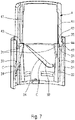
- the cam path C comprises three high points, three low points and three inclined segments. This helical path C can be compared to screw threads, but not projecting but recessed. At the level where the inner wall 33 defines high points, it is provided with inner bearing flanges 35 which project radially inwards. The top of these inner support flanges 35 is located at the same level as the profiled upper edge 34, as can be seen in the figure 7 and 8 .
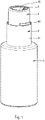
- the mobile cover 4 has a substantially cylindrical overall configuration. It is movable between a raised position, shown on the figure 1 , 3 , 4 , 5 , 6 and 7 and a withdrawn or lowered position, shown on the figure 2 and 8 . Initially, when the mobile cover 4 is in the raised position, it is blocked by a tear-off strip for first use 46 which blocks it with respect to the actuating ring 3, as can be seen in the figure 1 .
- the mobile cover 4 internally comprises one or more vertical rib(s) 41, which can extend over the entire height of the cover. At its lower end, each rib 41 forms a lower end edge 42 which forms an inner profile which engages the profiled upper edge 34 of the inner wall 33, as seen in the figure 6 , 7 and 8 .
- the cover 4 also forms a heel 43 engaged in the annular space 30 and defining an outer profile 44 which is engaged below the inner shoulder 32 of the outer wall 31.
- these heels 43 which can for example be three in number, are engaged in the helical path C.
- the inner profile 42 is arranged axially lower and on the inside with respect to the outer profile 32, in a completely corresponding manner with the arrangement of the profiled inner edge 34 with respect to the inner shoulder 32.
- the inner ribs 41 are engaged in the guide passages 265 formed by the pairs of studs 264 on the outer wall of the casing 26 of the pusher 2, as can be seen in the figure 5 .
- the movable cover 54 is thus locked in rotation with respect to the pusher 2, which itself is locked in rotation relative to the fixed mounting part 1, due to the engagement of the axial ribs 263 in the axial slots 16.
- the movable cover 4 is forced to follow the helical path C, due to of the engagement of its heels 43 between the inner 31 and outer 33 walls.
- the pusher 2 is blocked axially when the mobile cover 4 is not in its withdrawn position.
- the pusher 2 is blocked, given that the support edges 35 are then located below the lower edge 261 of the casing 26.
- the dispensing head of the invention provides additional functionalities, such as the axial blocking of the pusher and its angular indexing.
- the axial blocking is achieved, while the pusher 2 is entirely inscribed inside the mobile cover 4.
- the angular indexing of the pusher is done by means of the mounting part 1 which can be angularly indexed on the neck R1 of the R reservoir.
Landscapes
- Closures For Containers (AREA)
- Containers And Packaging Bodies Having A Special Means To Remove Contents (AREA)
Description
- La présente invention concerne une tête de distribution de produit fluide destinée à être associée à un organe de distribution tel qu'une pompe ou une valve pour constituer ensemble un distributeur de produit fluide. Les domaines privilégiés de l'invention sont ceux de la parfumerie, de la cosmétique et de la pharmacie.
- Dans l'art antérieur, on connait le document
US5004127 qui décrit une tête de distribution comprenant un cache mobile qui peut se déplacer axialement autour d'un poussoir muni d'un bec latéral saillant. Le cache mobile est déplaçable au moyen d'un mécanisme comprenant une pièce de montage fixe en prise avec un réservoir de produit fluide et une bague d'actionnement rotative. Le cache mobile est disposé entre la pièce de montage fixe et la bague d'actionnement. Le cache mobile est en prise filetée avec la pièce de montage fixe et est guidé axialement dans la bague d'actionnement. Ainsi, la rotation de la bague d'actionnement a pour effet d'entrainer le cache mobile, qui est contraint de se déplacer axialement du fait de sa prise filetée avec la pièce de montage fixe. En position étendue, le cache mobile vient se positionner juste en-dessous du bec latéral pour bloquer le poussoir. Toutefois, la mise en oeuvre d'un bec latéral n'est pas toujours possible ou souhaitable. - Dans l'art antérieur, on connait aussi le document
US6290103 qui décrit également une tête de distribution comprenant un cache mobile déplaçable au moyen d'une bague d'actionnement rotative. Le cache mobile entoure un poussoir équipé d'un gicleur latéral qui est masqué par le cache, lorsqu'il est en position étendue. Toutefois, il est possible d'actionner le poussoir, car rien ne le bloque en déplacement axial. De plus, le poussoir est libre de tourner sur lui-même, de sorte que l'on doit chercher le gicleur à chaque retrait du cache. - Dans l'art antérieur, on connaît aussi le document
JPH038160U - Un but de la présente invention est de bloquer le poussoir en déplacement axial, dès lors que le cache n'est pas en position retiré. Un autre but de l'invention est de fixer la position angulaire du gicleur. Encore un autre but est d'avoir un poussoir dont le gicleur latéral est masqué par le cache en position étendue.
- Pour atteindre ces buts, la présente invention propose que :
- le poussoir soit bloqué en rotation sur la pièce de montage fixe,
- le cache mobile soit bloqué en rotation sur le poussoir, et
- la bague d'actionnement soit montée rotative sur la pièce de montage fixe.
- Ainsi, le poussoir sert d'élément intermédiaire entre le cache et la pièce de montage fixe pour le guider axialement. Ce faisant, le poussoir est lui-même guidé axialement, c'est-à-dire bloqué en rotation. En d'autres termes, le poussoir participe au mécanisme de déplacement du cache mobile.
- Selon une caractéristique avantageuse, le poussoir est en butée axiale sur la bague d'actionnement rotative, lorsque le cache mobile n'est pas en position rétractée. Cela implique que le poussoir est débloqué dès lors que le cache mobile a quitté sa position rétractée. On évite ainsi toute distribution intempestive en-dehors des moments où l'on veut se servir du distributeur. Il est à noter que le cache mobile ne participe pas au blocage axial du poussoir, qui est assuré seul par la bague d'actionnement.
- Selon une autre caractéristique avantageuse, la bague d'actionnement peut comprendre deux parois concentriques définissant entre elles au moins un chemin hélicoïdal, le cache mobile étant en prise avec ce chemin hélicoïdal. Plus précisément, les deux parois concentriques peuvent comprendre une paroi extérieure, et une paroi intérieure qui s'étend à l'intérieur de la paroi extérieure, de manière à définir entre elles un espace annulaire, dans lequel est engagé le cache mobile. De préférence, le chemin hélicoïdal est formé entre un bord supérieur profilé de la paroi intérieure et un épaulement intérieur de la paroi extérieure qui est orienté vers le bas et profilé de manière correspondante au bord supérieur profilé. Avantageusement, le cache mobile peut comprendre un profil extérieur en prise avec l'épaulement intérieur et un profil intérieur en prise avec le bord supérieur profilé.
- Le cache est ainsi empêché de se déplacer librement vers le haut par l'épaulement intérieur et vers le bas par le bord supérieur profilé. Le chemin hélicoïdal est ainsi formé par une fente ou un interstice profilé(e) dont les bords sont respectivement formés par les deux parois concentriques de la bague d'actionnement. C'est cette conception à paroi double qui permet à la bague d'actionnement d'agir à la fois sur le cache avec le chemin hélicoïdal et sur le poussoir avec la paroi intérieure.
- Selon un mode de réalisation pratique, le cache mobile peut comprendre au moins une nervure axiale intérieure en prise avec un organe de guidage axial correspondant formé par le poussoir, afin de bloquer le cache mobile en rotation par rapport au poussoir. Avantageusement, le profil intérieur est formé par un bord d'extrémité inférieur de la nervure axiale intérieure.
- Selon un autre aspect pratique, la paroi intérieure peut former au moins un rebord d'appui intérieur, le poussoir formant un bord annulaire inférieur interrompu par autant d'échancrure que de rebord d'appui intérieur, le bord annulaire inférieur étant disposé axialement au-dessus du rebord d'appui intérieur, de manière à empêcher le déplacement axial du poussoir, hormis lorsque l'échancrure est disposée axialement au-dessus du rebord d'appui intérieur, correspondant à la position rétractée du cache mobile.
- Selon une autre caractéristique de l'invention, la pièce de montage fixe peut comprendre des moyens de montage sur le réservoir de produit fluide et des moyens de réception pour l'organe de distribution. Dans ce cas, la pièce de montage fixe remplit plusieurs fonctions, à savoir :
- Blocage en rotation ou guidage axial du poussoir,
- Montage rotatif de la bague d'actionnement,
- Fixation (étanche) sur le réservoir, et
- Réception (fixe et étanche) de l'organe de distribution.
- L'esprit de l'invention réside dans le fait d'enrichir les éléments constitutifs classiques d'une tête à cache mobile avec des fonctions supplémentaires pour assurer le blocage en rotation du poussoir et/ou son blocage en déplacement axial. Le rôle intercalaire du poussoir pour transmettre le blocage en rotation de la pièce de montage fixe au cache est une caractéristique de premier plan. Le rôle de la bague d'actionnement pour bloquer le poussoir en déplacement axial est une autre caractéristique de premier plan. La conception à double parois de la bague d'actionnement est encore une autre caractéristique de premier plan.
- L'invention sera maintenant plus amplement décrite en référence aux dessins joints, donnant à titre d'exemple non limitatif, un mode de réalisation de l'invention.
- Sur les figures :
- La
figure 1 est une vue en perspective d'un distributeur de l'invention avec le cache relevé, - La
figure 2 est une vue en perspective du distributeur de lafigure 1 avec le cache abaissé, - La
figure 3 est une vue en coupe transversale verticale à travers le distributeur de lafigure 1 , - La
figure 4 est une vue en coupe transversale verticale à travers la tête de distribution de lafigure 3 , avec le réservoir et l'organe de distribution retirés, - La
figure 5 est une vue en perspective de la tête de distribution des figures précédentes avec le cache relevé, mais représenté en transparence, - La
figure 6 est une vue similaire à celle de lafigure 5 selon un autre plan de coupe et sans la pièce de montage fixe, - La
figure 7 est une vue similaire à celle de lafigure 6 sans le poussoir, et - La
figure 8 est une vue similaire à celle de lafigure 6 avec le cache mobile abaissé. - On se référera tout d'abord aux
figures 1 à 3 pour décrire de manière globale les différents éléments constitutifs d'un distributeur de produit fluide selon une forme de réalisation de l'invention. - Le distributeur comprend un réservoir de produit fluide R qui comprend un col R1. Le réservoir R n'est pas un élément critique de la présente invention. Il peut être réalisé par toute technique avec des matériaux appropriés. Le réservoir peut être en verre, en plastique en métal, etc. Il est destiné à contenir un produit fluide qui peut être de toute nature, comme par exemple un parfum, un produit cosmétique, un produit moussant, un produit alimentaire, etc.
- Le distributeur comprend également un organe de distribution P, qui peut être une pompe ou une valve. L'organe de distribution P comprend une tige d'actionnement P1 qui est déplaçable axialement en va et vient à l'encontre d'un ressort de rappel (non représenté). L'organe de distribution P comprend également une bague de fixation P2 formant une collerette annulaire saillante P3. Il s'agit là d'un mode de réalisation non limitatif pour la bague de fixation P2.
- Le distributeur de l'invention comprend surtout une tête de distribution qui coopère à la fois avec le réservoir R et l'organe de distribution P. Cette tête de distribution comprend quatre éléments constitutifs, à savoir une pièce de montage fixe 1, un poussoir 2, une bague d'actionnement 3 et un cache mobile 4. Toutes ces pièces peuvent être réalisées par injection/moulage de matière plastique appropriée. Concernant le comportement dynamique de ces éléments constitutifs, la pièce de montage fixe 1 n'est pas déplaçable, le poussoir 2 est uniquement déplaçable axialement, la bague d'actionnement 3 est uniquement déplaçable en rotation et le cache mobile 4 est uniquement déplaçable axialement, mais indépendamment du poussoir 2.
- On se réfèrera maintenant indifféremment aux
figures 4 à 8 pour décrire en détail la structure et la coopération de ces quatre éléments constitutifs. - La pièce de montage fixe 1 comprend une jupe de fixation 11 qui forme intérieurement un ou plusieurs profil(s) de fixation 12 destiné(s) à coopérer avec le col R1 du réservoir R afin de fixer la pièce de montage 1 sur le réservoir R. Ces profils de fixation 12 peuvent être des profils d'encliquetage, de vissage, etc. Extérieurement, la jupe de fixation 11 comprend un ou plusieurs profil(s) saillant(s) 13 pour le montage rotatif de la bague d'actionnement 3, comme on le verra ci-après. La pièce de montage 1 comprend également une lèvre d'étanchéité 14 qui s'étend concentriquement à l'intérieur de la jupe de fixation 11. Cette lèvre d'étanchéité 14 est destinée à venir en contact étanche avec la paroi interne du col R1, comme on peut le voir sur la
figure 3 . De cette manière, la pièce de montage 1 est montée de manière fixe et étanche sur le col R1 au moyen des profils de fixation 12 et de la lèvre d'étanchéité 14. La pièce de montage 1 comprend également une couronne 15 qui s'étend vers le haut, sensiblement dans le prolongement de la jupe de fixation 11. Cette couronne 15 est interrompue par au moins une fente axiale 16 qui est ouverte vers le haut de la couronne. A sa base, la couronne 15 forme un logement de réception 17 pour la collerette saillante P3 de la bague de fixation P2, comme on peut le voir sur lafigure 3 . - Ainsi, la pièce de montage fixe 1 assure le montage fixe et étanche sur le col R1 du réservoir R, la réception fixe et étanche de l'organe de distribution P et le montage rotatif de la bague d'actionnement 3. Nous verrons ci-après que cette pièce de montage 1 assure également le guidage axial du poussoir 2 par l'intermédiaire de sa ou ses fente(s) axiale(s) 16.
- Le poussoir 2 présente une conception globale tout à fait classique, avec un manchon de raccordement 21 destiné à recevoir l'extrémité libre de la tige d'actionnement P1, comme on peut le voir sur la
figure 3 , un conduit d'alimentation 22 qui relie le manchon de raccordement 21 à un logement dans lequel est engagé un gicleur 23 formant un orifice de distribution 24. Le poussoir 2 comprend également une surface supérieure d'appui 25 sur laquelle l'utilisateur peut appuyer à l'aide d'un doigt, par exemple l'index, pour déplacer le poussoir 2 et la tige d'actionnement P1. Le poussoir 2 comprend également une enveloppe extérieure 26 sensiblement cylindrique qui s'étend vers le bas à partir de la périphérie externe de la surface supérieure d'appui 25. Le gicleur 23 débouche latéralement dans cette enveloppe extérieure 26. Elle définit un bord inférieur 261 de forme sensiblement annulaire, qui est cependant interrompu localement par une ou plusieurs échancrure(s) 262. L'enveloppe 26 comprend également une ou plusieurs nervure(s) axiale(s) 263, qui peuvent s'étendre de la surface supérieure d'appui 25 jusqu'à proximité du bord inférieure 261. Comme on peut le voir sur lafigure 5 , la paroi externe de l'enveloppe 26 comprend au moins une paire de plots 264 définissant entre eux un passage de guidage axiale 265. - La bague d'actionnement 3 est la pièce la plus complexe de la tête de distribution de l'invention. Cette bague 3 présente une conception à double paroi, à savoir une paroi extérieure 31 et une paroi intérieure 33, qui sont disposées de manière concentrique, en définissant entre elles un espace annulaire 30. Les deux parois 31 et 33 sont reliées l'une à l'autre par des entretoises (non représentées). Extérieurement, la paroi extérieure 31 est sensiblement régulière : elle peut toutefois comporter des stries de préhension. Intérieurement, la paroi extérieure 31 forme un épaulement 32 orienté vers le bas. Cet épaulement 32 présente un profil complexe avec des secteurs inclinés, comme on peut le voir sur les
figures 6 à 8 . La paroi intérieure 33 définit intérieurement au niveau de son extrémité inférieure des profils d'accrochage 36a et 36b qui coopèrent avec le profil de montage 13 de la pièce de montage fixe 1. L'assemblage de ces profils peut se faire par encliquetage sans frottement excessif, de manière à permettre la libre rotation de la bague d'actionnement 3 autour de la pièce de montage fixe 1. La paroi intérieure 33 comprend un bord supérieur profilé 34 qui suit la forme de l'épaulement intérieur 32 de la paroi extérieure 31, de manière à définir entre eux un chemin hélicoïdal C. Etant donné que les deux parois 31 et 33 sont concentriques, le bord supérieur profilé 34 est décalé radialement vers l'intérieur par rapport à l'épaulement intérieur 32. En outre, le bord supérieur profilé 34 est disposé axialement un peu plus bas que l'épaulement intérieur 32 de sorte que le chemin hélicoïdal C se présente sous la forme d'une fente orientée vers l'intérieur et vers le haut. Ce chemin hélicoïdal C comprend au moins un point haut et un point bas reliés entre eux par un segment incliné. Dans le mode de réalisation représenté sur les figures, le chemin de came C comprend trois points hauts, trois points bas et trois segments inclinés. Ce chemin hélicoïdal C peut être comparé à des filets de vis, mais non pas en saillie mais en creux. Au niveau où la paroi intérieure 33 définit des points hauts, elle est pourvue de rebords d'appui intérieurs 35 qui font saillie radialement vers l'intérieur. Le haut de ces rebords d'appui intérieur 35 est situé au même niveau que le bord supérieur profilé 34, comme on peut le voir sur lesfigures 7 et8 . - Le cache mobile 4 présente une configuration globale sensiblement cylindrique. Il est déplaçable entre une position relevée, représentée sur les
figures 1 ,3 ,4 ,5 ,6 et7 et une position retirée ou abaissée, représentée sur lesfigures 2 et8 . Initialement, lorsque le cache mobile 4 est en position relevée, il est bloqué par une bande arrachable de premier usage 46 qui le bloque par rapport à la bague d'actionnement 3, comme on peut le voir sur lafigure 1 . Le cache mobile 4 comprend intérieurement une ou plusieurs nervure(s) verticale(s) 41, qui peuvent s'étendre sur la totalité de la hauteur du cache. A son extrémité inférieure, chaque nervure 41 forme un bord d'extrémité inférieure 42 qui forme un profil intérieur qui vient en prise avec le bord supérieur profilé 34 de la paroi intérieure 33, comme on le voit sur lesfigures 6 ,7 et8 . Au niveau de chaque nervure axiale 41, le cache 4 forme également un talon 43 engagé dans l'espace annulaire 30 et définissant un profil extérieur 44 qui est engagé en dessous de l'épaulement intérieur 32 de la paroi extérieure 31. On peut également dire que ces talons 43, qui peuvent par exemple être au nombre de trois, sont en prise dans le chemin hélicoïdal C. On peut clairement voir sur lesfigures 6 ,7 et8 , que le profil intérieur 42 est disposé axialement plus bas et à l'intérieur par rapport au profil extérieur 32, de manière tout à fait correspondante avec la disposition du bord intérieur profilé 34 par rapport à l'épaulement intérieur 32. D'autre part, les nervures intérieures 41 sont engagées dans les passages de guidage 265 formés par les paires de plots 264 sur la paroi extérieure de l'enveloppe 26 du poussoir 2, comme on peut le voir sur lafigure 5 . Le cache mobile 54 est ainsi bloqué en rotation par rapport au poussoir 2, qui lui-même est bloqué en rotation par rapport à la pièce de montage fixe 1, du fait de l'engagement des nervures axiales 263 dans les fentes axiales 16. D'autre part, le cache mobile 4 est contraint de suivre le chemin hélicoïdal C, du fait de l'engagement de ses talons 43 entre les parois intérieur 31 et extérieur 33. - On comprend alors aisément que la rotation de la bague d'actionnement 2 engendre le déplacement axial du cache mobile 4 autour du poussoir 2, jusqu'à masquer son gicleur 23. On peut également remarquer que le cache mobile 4 se déplace à l'intérieur de l'espace annulaire 30 défini entre les deux parois 31 et 33. Lorsque le cache mobile 4 est en position relevée, comme représenté sur les
figures 6 et7 , on peut voir que le bord inférieur 261 de l'enveloppe 26 est situé au-dessus des rebords d'appui intérieurs 35, de sorte qu'il n'est pas possible de le déplacer axialement. En tournant la bague d'actionnement 3, les rebords d'appui 35 se déplacent sous le bord inférieur 261 jusqu'à venir en alignement axial avec les échancrures 262, comme représenté sur lafigure 8 . Le cache mobile 4 est alors dans sa position abaissée ou retirée. On peut donc noter que le poussoir 2 est bloqué axialement lorsque le cache mobile 4 n'est pas dans sa position retirée. Lorsque le cache mobile 4 se déplace de sa position retirée vers sa position relevée, le poussoir 2 est bloqué, étant donné que les rebords d'appui 35 sont alors situés en dessous du bord inférieur 261 de l'enveloppe 26. - La tête de distribution de l'invention présente donc les caractéristiques suivantes :
- guidage axial du poussoir 2 sur la pièce de montage 1,
- guidage axial du cache 4 sur le poussoir 2,
- rotation de la bague d'actionnement 3 sur la pièce de montage 1,
- blocage axial du poussoir 2 sur la bague d'actionnement 3,
- bague d'actionnement 3 à double paroi,
- formation d'un chemin hélicoïdal C entre les deux parois,
- engagement du cache 4 entre les deux parois de la bague d'actionnement 3,
- pièce de montage 1 fixée sur le col du réservoir R,
- pièce de montage 1 recevant la pompe ou la valve P.
- Par rapport à une tête de distribution classique mettant en œuvre un cache mobile, la tête de distribution de l'invention apporte des fonctionnalités supplémentaires, comme le blocage axial du poussoir et son indexation angulaire. Le blocage axial est réalisé, alors que le poussoir 2 est entièrement inscrit à l'intérieur du cache mobile 4. L'indexation angulaire du poussoir se fait par l'intermédiaire de la pièce de montage 1 qui peut être indexée angulairement sur le col R1 du réservoir R.
- On dispose ainsi d'une tête de distribution à cache mobile et gicleur orientés de sorte qu'il n'est pas nécessaire de chercher le gicleur, une fois le cache mobile retiré.
Claims (10)
- Tête de distribution de produit fluide destinée à être montée sur un réservoir de produit fluide (R) et à coopérer avec un organe de distribution (P), tel qu'une pompe, la tête de distribution de produit fluide comprenant :- une pièce de montage fixe (1) destinée à être montée sur le réservoir de produit fluide (R),- un poussoir (2) destiné à être monté sur l'organe de distribution (P),- une bague d'actionnement (3), et- un cache mobile (4) qui se déplace axialement autour du poussoir (2) entre une position étendue dans laquelle le cache mobile (4) masque le poussoir (2) et une position rétractée dans laquelle le poussoir (2) est dégagé, la rotation de la bague d'actionnement (3) entrainant le cache mobile (4) en déplacement axial, où:- le poussoir (2) est bloqué en rotation sur la pièce de montage fixe (1),- le cache mobile (4) est bloqué en rotation sur le poussoir (1), la tête de distribution étant caractérisée en ce que :- la bague d'actionnement (3) est montée rotative sur la pièce de montage fixe (1).
- Tête de distribution selon la revendication 1, dans laquelle le poussoir (2) est en butée axiale sur la bague d'actionnement rotative (3), lorsque le cache mobile (4) n'est pas en position rétractée.
- Tête de distribution selon la revendication 1 ou 2, dans laquelle la bague d'actionnement rotative (3) comprend deux parois concentriques (31, 33) définissant entre elles au moins un chemin hélicoïdal (C), le cache mobile (4) étant en prise avec ce chemin hélicoïdal (C).
- Tête de distribution selon la revendication 3, dans laquelle les deux parois concentriques comprennent une paroi extérieure (31), et une paroi intérieure (33) qui s'étend à l'intérieur de la paroi extérieure (31), de manière à définir entre elles un espace annulaire (30), le cache mobile (4) étant engagé dans cet espace annulaire (30).
- Tête de distribution selon la revendication 4, dans laquelle le chemin hélicoïdal (C) est formé entre un bord supérieur profilé (34) de la paroi intérieure (33) et un épaulement intérieur (32) de la paroi extérieure (31) qui est orienté vers le bas et profilé de manière correspondante au bord supérieur profilé (34).
- Tête de distribution selon la revendication 5, dans laquelle le cache mobile (4) comprend un profil extérieur (44) en prise avec l'épaulement intérieur (32) et un profil intérieur (42) en prise avec le bord supérieur profilé (34).
- Tête de distribution selon l'une quelconque des revendications précédentes, dans laquelle le cache mobile (4) comprend au moins une nervure axiale intérieure (41) en prise avec un organe de guidage axial (264) correspondant formé par le poussoir (2), afin de bloquer le cache mobile (4) en rotation par rapport au poussoir (2).
- Tête de distribution selon les revendications 6 et 7, dans laquelle le profil intérieur (42) est formé par un bord d'extrémité inférieur de la nervure axiale intérieure (41).
- Tête de distribution selon l'une quelconque des revendications 4 à 6, dans laquelle la paroi intérieure (32) forme au moins un rebord d'appui intérieur (35), le poussoir (2) formant un bord annulaire inférieur (261) interrompu par autant d'échancrure (262) que de rebord d'appui intérieur (35), le bord annulaire inférieur (261) étant disposé axialement au-dessus du rebord d'appui intérieur (35), de manière à empêcher le déplacement axial du poussoir (2), hormis lorsque l'échancrure (262) est disposée axialement au-dessus du rebord d'appui intérieur (35), correspondant à la position rétractée du cache mobile (4).
- Tête de distribution selon l'une quelconque des revendications précédentes, dans laquelle la pièce de montage fixe (1) comprend des moyens de montage (11) sur le réservoir de produit fluide (R) et des moyens de réception (17) pour l'organe de distribution (P).
Applications Claiming Priority (2)
| Application Number | Priority Date | Filing Date | Title |
|---|---|---|---|
| FR1852553A FR3079219B1 (fr) | 2018-03-23 | 2018-03-23 | Tete de distribution de produit fluide. |
| PCT/FR2019/050658 WO2019180392A1 (fr) | 2018-03-23 | 2019-03-22 | Tête de distribution de produit fluide |
Publications (2)
| Publication Number | Publication Date |
|---|---|
| EP3768436A1 EP3768436A1 (fr) | 2021-01-27 |
| EP3768436B1 true EP3768436B1 (fr) | 2022-05-04 |
Family
ID=62597696
Family Applications (1)
| Application Number | Title | Priority Date | Filing Date |
|---|---|---|---|
| EP19718791.7A Active EP3768436B1 (fr) | 2018-03-23 | 2019-03-22 | Tête de distribution de produit fluide |
Country Status (3)
| Country | Link |
|---|---|
| EP (1) | EP3768436B1 (fr) |
| FR (1) | FR3079219B1 (fr) |
| WO (1) | WO2019180392A1 (fr) |
Family Cites Families (6)
| Publication number | Priority date | Publication date | Assignee | Title |
|---|---|---|---|---|
| FR2644432B2 (fr) | 1988-05-11 | 1991-06-14 | Morel Simone | Capsule a enveloppe tournante pour flacons et recipients analogues |
| JPH0725331Y2 (ja) * | 1989-06-14 | 1995-06-07 | 釜屋化学工業株式会社 | 注出容器 |
| EP0987189B1 (fr) | 1998-09-15 | 2003-01-29 | Lir-Usa Manufacturing Co. Inc. | Dispositif bouchon escamotable pour la protection d'un actionneur de pompe et récipient comprenant ledit dispositif |
| JP4756496B2 (ja) * | 2004-12-22 | 2011-08-24 | ザ プロクター アンド ギャンブル カンパニー | ポンプ付き注出容器 |
| KR100916719B1 (ko) * | 2007-11-12 | 2009-09-14 | 주식회사 태성산업 | 화장품용기 |
| EP2859957B1 (fr) * | 2013-10-14 | 2019-12-18 | Yonwoo Co., Ltd. | Conteneur pour cosmétique du type à pompage et couvercle intégré |
-
2018
- 2018-03-23 FR FR1852553A patent/FR3079219B1/fr not_active Expired - Fee Related
-
2019
- 2019-03-22 EP EP19718791.7A patent/EP3768436B1/fr active Active
- 2019-03-22 WO PCT/FR2019/050658 patent/WO2019180392A1/fr not_active Ceased
Also Published As
| Publication number | Publication date |
|---|---|
| EP3768436A1 (fr) | 2021-01-27 |
| WO2019180392A1 (fr) | 2019-09-26 |
| FR3079219A1 (fr) | 2019-09-27 |
| FR3079219B1 (fr) | 2020-04-17 |
Similar Documents
| Publication | Publication Date | Title |
|---|---|---|
| EP2091836B1 (fr) | Distributeur de produit fluide | |
| EP2916964B1 (fr) | Distributeur de produit fluide | |
| EP2694388B1 (fr) | Distributeur compte-gouttes. | |
| EP2509716B1 (fr) | Tete de distribution de produit fluide | |
| EP0337867B1 (fr) | Distributeur rechargeable comportant un piston translatable | |
| FR2978742A1 (fr) | Distributeur de produit fluide. | |
| FR3065155A1 (fr) | Ensemble de conditionnement et de distribution d'un produit fluide avec reprise d'air | |
| EP3645172B1 (fr) | Distributeur duo | |
| EP2135682B2 (fr) | Flacon de distribution d'un produit fluide comprenant un manchon de maintien de la pompe de distribution déformable et dévissable | |
| CH659634A5 (fr) | Ensemble pour le conditionnement et l'application d'une substance de type vernis. | |
| EP2461716B1 (fr) | Dispositif de produit cosmetique presentant un orifice de distribution | |
| EP3895579A1 (fr) | Mécanisme pour un réceptacle d'application d'un produit cosmétique et réceptacle comportant un tel mécanisme | |
| FR3079219A1 (fr) | Tete de distribution de produit fluide. | |
| FR3079725A1 (fr) | Dispositif de fermeture pour récipient préssurisé contenant un produit, notamment un produit cosmétique | |
| EP1828021B1 (fr) | Dispositif de distribution d'un produit fluide ou pâteux | |
| FR2864044A1 (fr) | Distributeur de produit fluide. | |
| FR3095133A1 (fr) | Distributeur de produit fluide | |
| FR3098202A1 (fr) | Dispositif de fixation d’un dispositif de distribution | |
| EP2996815B1 (fr) | Ensemble de distribution de produit fluide | |
| FR2687568A1 (fr) | Panier d'instillation pour ensemble de conditionnement et de distribution de collyre, et ensemble de conditionnement et de distribution associe. | |
| FR2876557A1 (fr) | Stylo distributeur d'un produit cosmetique fluide | |
| EP4719934A1 (fr) | Distributeur de poudre rechargeable | |
| EP4399153B1 (fr) | Tete de remplissage d'un dispositif de distribution de produit fluide comportant une valve | |
| FR2811636A1 (fr) | Dispositif pour le conditionnement separe de deux ou trois composants a melanger extemporanement | |
| FR3069140A1 (fr) | Mecanisme de came, en particulier pour un applicateur de produit cosmetique |
Legal Events
| Date | Code | Title | Description |
|---|---|---|---|
| STAA | Information on the status of an ep patent application or granted ep patent |
Free format text: STATUS: UNKNOWN |
|
| STAA | Information on the status of an ep patent application or granted ep patent |
Free format text: STATUS: THE INTERNATIONAL PUBLICATION HAS BEEN MADE |
|
| PUAI | Public reference made under article 153(3) epc to a published international application that has entered the european phase |
Free format text: ORIGINAL CODE: 0009012 |
|
| STAA | Information on the status of an ep patent application or granted ep patent |
Free format text: STATUS: REQUEST FOR EXAMINATION WAS MADE |
|
| 17P | Request for examination filed |
Effective date: 20201020 |
|
| AK | Designated contracting states |
Kind code of ref document: A1 Designated state(s): AL AT BE BG CH CY CZ DE DK EE ES FI FR GB GR HR HU IE IS IT LI LT LU LV MC MK MT NL NO PL PT RO RS SE SI SK SM TR |
|
| AX | Request for extension of the european patent |
Extension state: BA ME |
|
| DAV | Request for validation of the european patent (deleted) | ||
| DAX | Request for extension of the european patent (deleted) | ||
| GRAP | Despatch of communication of intention to grant a patent |
Free format text: ORIGINAL CODE: EPIDOSNIGR1 |
|
| STAA | Information on the status of an ep patent application or granted ep patent |
Free format text: STATUS: GRANT OF PATENT IS INTENDED |
|
| INTG | Intention to grant announced |
Effective date: 20211203 |
|
| GRAS | Grant fee paid |
Free format text: ORIGINAL CODE: EPIDOSNIGR3 |
|
| GRAA | (expected) grant |
Free format text: ORIGINAL CODE: 0009210 |
|
| STAA | Information on the status of an ep patent application or granted ep patent |
Free format text: STATUS: THE PATENT HAS BEEN GRANTED |
|
| AK | Designated contracting states |
Kind code of ref document: B1 Designated state(s): AL AT BE BG CH CY CZ DE DK EE ES FI FR GB GR HR HU IE IS IT LI LT LU LV MC MK MT NL NO PL PT RO RS SE SI SK SM TR |
|
| REG | Reference to a national code |
Ref country code: GB Ref legal event code: FG4D Free format text: NOT ENGLISH |
|
| REG | Reference to a national code |
Ref country code: CH Ref legal event code: EP |
|
| REG | Reference to a national code |
Ref country code: AT Ref legal event code: REF Ref document number: 1488451 Country of ref document: AT Kind code of ref document: T Effective date: 20220515 |
|
| REG | Reference to a national code |
Ref country code: DE Ref legal event code: R096 Ref document number: 602019014540 Country of ref document: DE |
|
| REG | Reference to a national code |
Ref country code: IE Ref legal event code: FG4D Free format text: LANGUAGE OF EP DOCUMENT: FRENCH |
|
| REG | Reference to a national code |
Ref country code: LT Ref legal event code: MG9D |
|
| REG | Reference to a national code |
Ref country code: NL Ref legal event code: MP Effective date: 20220504 |
|
| REG | Reference to a national code |
Ref country code: AT Ref legal event code: MK05 Ref document number: 1488451 Country of ref document: AT Kind code of ref document: T Effective date: 20220504 |
|
| PG25 | Lapsed in a contracting state [announced via postgrant information from national office to epo] |
Ref country code: SE Free format text: LAPSE BECAUSE OF FAILURE TO SUBMIT A TRANSLATION OF THE DESCRIPTION OR TO PAY THE FEE WITHIN THE PRESCRIBED TIME-LIMIT Effective date: 20220504 Ref country code: PT Free format text: LAPSE BECAUSE OF FAILURE TO SUBMIT A TRANSLATION OF THE DESCRIPTION OR TO PAY THE FEE WITHIN THE PRESCRIBED TIME-LIMIT Effective date: 20220905 Ref country code: NO Free format text: LAPSE BECAUSE OF FAILURE TO SUBMIT A TRANSLATION OF THE DESCRIPTION OR TO PAY THE FEE WITHIN THE PRESCRIBED TIME-LIMIT Effective date: 20220804 Ref country code: NL Free format text: LAPSE BECAUSE OF FAILURE TO SUBMIT A TRANSLATION OF THE DESCRIPTION OR TO PAY THE FEE WITHIN THE PRESCRIBED TIME-LIMIT Effective date: 20220504 Ref country code: LT Free format text: LAPSE BECAUSE OF FAILURE TO SUBMIT A TRANSLATION OF THE DESCRIPTION OR TO PAY THE FEE WITHIN THE PRESCRIBED TIME-LIMIT Effective date: 20220504 Ref country code: HR Free format text: LAPSE BECAUSE OF FAILURE TO SUBMIT A TRANSLATION OF THE DESCRIPTION OR TO PAY THE FEE WITHIN THE PRESCRIBED TIME-LIMIT Effective date: 20220504 Ref country code: GR Free format text: LAPSE BECAUSE OF FAILURE TO SUBMIT A TRANSLATION OF THE DESCRIPTION OR TO PAY THE FEE WITHIN THE PRESCRIBED TIME-LIMIT Effective date: 20220805 Ref country code: FI Free format text: LAPSE BECAUSE OF FAILURE TO SUBMIT A TRANSLATION OF THE DESCRIPTION OR TO PAY THE FEE WITHIN THE PRESCRIBED TIME-LIMIT Effective date: 20220504 Ref country code: BG Free format text: LAPSE BECAUSE OF FAILURE TO SUBMIT A TRANSLATION OF THE DESCRIPTION OR TO PAY THE FEE WITHIN THE PRESCRIBED TIME-LIMIT Effective date: 20220804 Ref country code: AT Free format text: LAPSE BECAUSE OF FAILURE TO SUBMIT A TRANSLATION OF THE DESCRIPTION OR TO PAY THE FEE WITHIN THE PRESCRIBED TIME-LIMIT Effective date: 20220504 |
|
| PG25 | Lapsed in a contracting state [announced via postgrant information from national office to epo] |
Ref country code: RS Free format text: LAPSE BECAUSE OF FAILURE TO SUBMIT A TRANSLATION OF THE DESCRIPTION OR TO PAY THE FEE WITHIN THE PRESCRIBED TIME-LIMIT Effective date: 20220504 Ref country code: PL Free format text: LAPSE BECAUSE OF FAILURE TO SUBMIT A TRANSLATION OF THE DESCRIPTION OR TO PAY THE FEE WITHIN THE PRESCRIBED TIME-LIMIT Effective date: 20220504 Ref country code: LV Free format text: LAPSE BECAUSE OF FAILURE TO SUBMIT A TRANSLATION OF THE DESCRIPTION OR TO PAY THE FEE WITHIN THE PRESCRIBED TIME-LIMIT Effective date: 20220504 Ref country code: IS Free format text: LAPSE BECAUSE OF FAILURE TO SUBMIT A TRANSLATION OF THE DESCRIPTION OR TO PAY THE FEE WITHIN THE PRESCRIBED TIME-LIMIT Effective date: 20220904 |
|
| PG25 | Lapsed in a contracting state [announced via postgrant information from national office to epo] |
Ref country code: SM Free format text: LAPSE BECAUSE OF FAILURE TO SUBMIT A TRANSLATION OF THE DESCRIPTION OR TO PAY THE FEE WITHIN THE PRESCRIBED TIME-LIMIT Effective date: 20220504 Ref country code: SK Free format text: LAPSE BECAUSE OF FAILURE TO SUBMIT A TRANSLATION OF THE DESCRIPTION OR TO PAY THE FEE WITHIN THE PRESCRIBED TIME-LIMIT Effective date: 20220504 Ref country code: RO Free format text: LAPSE BECAUSE OF FAILURE TO SUBMIT A TRANSLATION OF THE DESCRIPTION OR TO PAY THE FEE WITHIN THE PRESCRIBED TIME-LIMIT Effective date: 20220504 Ref country code: ES Free format text: LAPSE BECAUSE OF FAILURE TO SUBMIT A TRANSLATION OF THE DESCRIPTION OR TO PAY THE FEE WITHIN THE PRESCRIBED TIME-LIMIT Effective date: 20220504 Ref country code: EE Free format text: LAPSE BECAUSE OF FAILURE TO SUBMIT A TRANSLATION OF THE DESCRIPTION OR TO PAY THE FEE WITHIN THE PRESCRIBED TIME-LIMIT Effective date: 20220504 Ref country code: DK Free format text: LAPSE BECAUSE OF FAILURE TO SUBMIT A TRANSLATION OF THE DESCRIPTION OR TO PAY THE FEE WITHIN THE PRESCRIBED TIME-LIMIT Effective date: 20220504 Ref country code: CZ Free format text: LAPSE BECAUSE OF FAILURE TO SUBMIT A TRANSLATION OF THE DESCRIPTION OR TO PAY THE FEE WITHIN THE PRESCRIBED TIME-LIMIT Effective date: 20220504 |
|
| REG | Reference to a national code |
Ref country code: DE Ref legal event code: R097 Ref document number: 602019014540 Country of ref document: DE |
|
| PLBE | No opposition filed within time limit |
Free format text: ORIGINAL CODE: 0009261 |
|
| STAA | Information on the status of an ep patent application or granted ep patent |
Free format text: STATUS: NO OPPOSITION FILED WITHIN TIME LIMIT |
|
| PG25 | Lapsed in a contracting state [announced via postgrant information from national office to epo] |
Ref country code: AL Free format text: LAPSE BECAUSE OF FAILURE TO SUBMIT A TRANSLATION OF THE DESCRIPTION OR TO PAY THE FEE WITHIN THE PRESCRIBED TIME-LIMIT Effective date: 20220504 |
|
| 26N | No opposition filed |
Effective date: 20230207 |
|
| PG25 | Lapsed in a contracting state [announced via postgrant information from national office to epo] |
Ref country code: SI Free format text: LAPSE BECAUSE OF FAILURE TO SUBMIT A TRANSLATION OF THE DESCRIPTION OR TO PAY THE FEE WITHIN THE PRESCRIBED TIME-LIMIT Effective date: 20220504 |
|
| P01 | Opt-out of the competence of the unified patent court (upc) registered |
Effective date: 20230525 |
|
| PG25 | Lapsed in a contracting state [announced via postgrant information from national office to epo] |
Ref country code: MC Free format text: LAPSE BECAUSE OF FAILURE TO SUBMIT A TRANSLATION OF THE DESCRIPTION OR TO PAY THE FEE WITHIN THE PRESCRIBED TIME-LIMIT Effective date: 20220504 |
|
| REG | Reference to a national code |
Ref country code: CH Ref legal event code: PL |
|
| REG | Reference to a national code |
Ref country code: BE Ref legal event code: MM Effective date: 20230331 |
|
| PG25 | Lapsed in a contracting state [announced via postgrant information from national office to epo] |
Ref country code: LU Free format text: LAPSE BECAUSE OF NON-PAYMENT OF DUE FEES Effective date: 20230322 |
|
| REG | Reference to a national code |
Ref country code: IE Ref legal event code: MM4A |
|
| PG25 | Lapsed in a contracting state [announced via postgrant information from national office to epo] |
Ref country code: LI Free format text: LAPSE BECAUSE OF NON-PAYMENT OF DUE FEES Effective date: 20230331 Ref country code: IE Free format text: LAPSE BECAUSE OF NON-PAYMENT OF DUE FEES Effective date: 20230322 Ref country code: CH Free format text: LAPSE BECAUSE OF NON-PAYMENT OF DUE FEES Effective date: 20230331 |
|
| PG25 | Lapsed in a contracting state [announced via postgrant information from national office to epo] |
Ref country code: BE Free format text: LAPSE BECAUSE OF NON-PAYMENT OF DUE FEES Effective date: 20230331 |
|
| PG25 | Lapsed in a contracting state [announced via postgrant information from national office to epo] |
Ref country code: BG Free format text: LAPSE BECAUSE OF FAILURE TO SUBMIT A TRANSLATION OF THE DESCRIPTION OR TO PAY THE FEE WITHIN THE PRESCRIBED TIME-LIMIT Effective date: 20220504 |
|
| PG25 | Lapsed in a contracting state [announced via postgrant information from national office to epo] |
Ref country code: BG Free format text: LAPSE BECAUSE OF FAILURE TO SUBMIT A TRANSLATION OF THE DESCRIPTION OR TO PAY THE FEE WITHIN THE PRESCRIBED TIME-LIMIT Effective date: 20220504 |
|
| PG25 | Lapsed in a contracting state [announced via postgrant information from national office to epo] |
Ref country code: CY Free format text: LAPSE BECAUSE OF FAILURE TO SUBMIT A TRANSLATION OF THE DESCRIPTION OR TO PAY THE FEE WITHIN THE PRESCRIBED TIME-LIMIT; INVALID AB INITIO Effective date: 20190322 |
|
| PG25 | Lapsed in a contracting state [announced via postgrant information from national office to epo] |
Ref country code: HU Free format text: LAPSE BECAUSE OF FAILURE TO SUBMIT A TRANSLATION OF THE DESCRIPTION OR TO PAY THE FEE WITHIN THE PRESCRIBED TIME-LIMIT; INVALID AB INITIO Effective date: 20190322 |
|
| PG25 | Lapsed in a contracting state [announced via postgrant information from national office to epo] |
Ref country code: TR Free format text: LAPSE BECAUSE OF FAILURE TO SUBMIT A TRANSLATION OF THE DESCRIPTION OR TO PAY THE FEE WITHIN THE PRESCRIBED TIME-LIMIT Effective date: 20220504 |
|
| PGFP | Annual fee paid to national office [announced via postgrant information from national office to epo] |
Ref country code: GB Payment date: 20260323 Year of fee payment: 8 |
|
| PGFP | Annual fee paid to national office [announced via postgrant information from national office to epo] |
Ref country code: DE Payment date: 20260313 Year of fee payment: 8 |
|
| PGFP | Annual fee paid to national office [announced via postgrant information from national office to epo] |
Ref country code: IT Payment date: 20260309 Year of fee payment: 8 |
|
| PGFP | Annual fee paid to national office [announced via postgrant information from national office to epo] |
Ref country code: FR Payment date: 20260330 Year of fee payment: 8 |