EP1828021B1 - Dispositif de distribution d'un produit fluide ou pâteux - Google Patents
Dispositif de distribution d'un produit fluide ou pâteux Download PDFInfo
- Publication number
- EP1828021B1 EP1828021B1 EP05826571A EP05826571A EP1828021B1 EP 1828021 B1 EP1828021 B1 EP 1828021B1 EP 05826571 A EP05826571 A EP 05826571A EP 05826571 A EP05826571 A EP 05826571A EP 1828021 B1 EP1828021 B1 EP 1828021B1
- Authority
- EP
- European Patent Office
- Prior art keywords
- dispensing
- ring
- fact
- dispensing device
- container
- Prior art date
- Legal status (The legal status is an assumption and is not a legal conclusion. Google has not performed a legal analysis and makes no representation as to the accuracy of the status listed.)
- Active
Links
- 239000012530 fluid Substances 0.000 title claims abstract description 9
- 235000011837 pasties Nutrition 0.000 title claims abstract description 9
- 230000000295 complement effect Effects 0.000 claims description 5
- 238000011144 upstream manufacturing Methods 0.000 claims description 2
- 238000009834 vaporization Methods 0.000 description 10
- 230000008016 vaporization Effects 0.000 description 7
- 239000006200 vaporizer Substances 0.000 description 6
- 238000007789 sealing Methods 0.000 description 5
- 230000000903 blocking effect Effects 0.000 description 4
- 239000007921 spray Substances 0.000 description 3
- 230000000694 effects Effects 0.000 description 2
- 239000002245 particle Substances 0.000 description 2
- 230000000284 resting effect Effects 0.000 description 2
- 240000009226 Corylus americana Species 0.000 description 1
- 235000001543 Corylus americana Nutrition 0.000 description 1
- 235000007466 Corylus avellana Nutrition 0.000 description 1
- 244000273618 Sphenoclea zeylanica Species 0.000 description 1
- 240000008042 Zea mays Species 0.000 description 1
- 230000009172 bursting Effects 0.000 description 1
- 239000002537 cosmetic Substances 0.000 description 1
- 239000006071 cream Substances 0.000 description 1
- 230000000994 depressogenic effect Effects 0.000 description 1
- 238000007599 discharging Methods 0.000 description 1
- 239000007788 liquid Substances 0.000 description 1
- 238000000465 moulding Methods 0.000 description 1
- 239000002304 perfume Substances 0.000 description 1
- 239000000825 pharmaceutical preparation Substances 0.000 description 1
- 229940127557 pharmaceutical product Drugs 0.000 description 1
- XLYOFNOQVPJJNP-UHFFFAOYSA-N water Substances O XLYOFNOQVPJJNP-UHFFFAOYSA-N 0.000 description 1
Images

Classifications
-
- B—PERFORMING OPERATIONS; TRANSPORTING
- B65—CONVEYING; PACKING; STORING; HANDLING THIN OR FILAMENTARY MATERIAL
- B65D—CONTAINERS FOR STORAGE OR TRANSPORT OF ARTICLES OR MATERIALS, e.g. BAGS, BARRELS, BOTTLES, BOXES, CANS, CARTONS, CRATES, DRUMS, JARS, TANKS, HOPPERS, FORWARDING CONTAINERS; ACCESSORIES, CLOSURES, OR FITTINGS THEREFOR; PACKAGING ELEMENTS; PACKAGES
- B65D83/00—Containers or packages with special means for dispensing contents
- B65D83/14—Containers or packages with special means for dispensing contents for delivery of liquid or semi-liquid contents by internal gaseous pressure, i.e. aerosol containers comprising propellant for a product delivered by a propellant
- B65D83/16—Containers or packages with special means for dispensing contents for delivery of liquid or semi-liquid contents by internal gaseous pressure, i.e. aerosol containers comprising propellant for a product delivered by a propellant characterised by the actuating means
- B65D83/20—Containers or packages with special means for dispensing contents for delivery of liquid or semi-liquid contents by internal gaseous pressure, i.e. aerosol containers comprising propellant for a product delivered by a propellant characterised by the actuating means operated by manual action, e.g. button-type actuator or actuator caps
- B65D83/205—Actuator caps, or peripheral actuator skirts, attachable to the aerosol container
-
- B—PERFORMING OPERATIONS; TRANSPORTING
- B05—SPRAYING OR ATOMISING IN GENERAL; APPLYING FLUENT MATERIALS TO SURFACES, IN GENERAL
- B05B—SPRAYING APPARATUS; ATOMISING APPARATUS; NOZZLES
- B05B11/00—Single-unit hand-held apparatus in which flow of contents is produced by the muscular force of the operator at the moment of use
- B05B11/0005—Components or details
- B05B11/0027—Means for neutralising the actuation of the sprayer ; Means for preventing access to the sprayer actuation means
- B05B11/0032—Manually actuated means located downstream the discharge nozzle for closing or covering it, e.g. shutters
-
- B—PERFORMING OPERATIONS; TRANSPORTING
- B05—SPRAYING OR ATOMISING IN GENERAL; APPLYING FLUENT MATERIALS TO SURFACES, IN GENERAL
- B05B—SPRAYING APPARATUS; ATOMISING APPARATUS; NOZZLES
- B05B11/00—Single-unit hand-held apparatus in which flow of contents is produced by the muscular force of the operator at the moment of use
- B05B11/01—Single-unit hand-held apparatus in which flow of contents is produced by the muscular force of the operator at the moment of use characterised by the means producing the flow
- B05B11/10—Pump arrangements for transferring the contents from the container to a pump chamber by a sucking effect and forcing the contents out through the dispensing nozzle
- B05B11/1042—Components or details
- B05B11/1059—Means for locking a pump or its actuation means in a fixed position
-
- B—PERFORMING OPERATIONS; TRANSPORTING
- B65—CONVEYING; PACKING; STORING; HANDLING THIN OR FILAMENTARY MATERIAL
- B65D—CONTAINERS FOR STORAGE OR TRANSPORT OF ARTICLES OR MATERIALS, e.g. BAGS, BARRELS, BOTTLES, BOXES, CANS, CARTONS, CRATES, DRUMS, JARS, TANKS, HOPPERS, FORWARDING CONTAINERS; ACCESSORIES, CLOSURES, OR FITTINGS THEREFOR; PACKAGING ELEMENTS; PACKAGES
- B65D83/00—Containers or packages with special means for dispensing contents
- B65D83/14—Containers or packages with special means for dispensing contents for delivery of liquid or semi-liquid contents by internal gaseous pressure, i.e. aerosol containers comprising propellant for a product delivered by a propellant
- B65D83/16—Containers or packages with special means for dispensing contents for delivery of liquid or semi-liquid contents by internal gaseous pressure, i.e. aerosol containers comprising propellant for a product delivered by a propellant characterised by the actuating means
- B65D83/22—Containers or packages with special means for dispensing contents for delivery of liquid or semi-liquid contents by internal gaseous pressure, i.e. aerosol containers comprising propellant for a product delivered by a propellant characterised by the actuating means with a mechanical means to disable actuation
-
- B—PERFORMING OPERATIONS; TRANSPORTING
- B65—CONVEYING; PACKING; STORING; HANDLING THIN OR FILAMENTARY MATERIAL
- B65D—CONTAINERS FOR STORAGE OR TRANSPORT OF ARTICLES OR MATERIALS, e.g. BAGS, BARRELS, BOTTLES, BOXES, CANS, CARTONS, CRATES, DRUMS, JARS, TANKS, HOPPERS, FORWARDING CONTAINERS; ACCESSORIES, CLOSURES, OR FITTINGS THEREFOR; PACKAGING ELEMENTS; PACKAGES
- B65D83/00—Containers or packages with special means for dispensing contents
- B65D83/14—Containers or packages with special means for dispensing contents for delivery of liquid or semi-liquid contents by internal gaseous pressure, i.e. aerosol containers comprising propellant for a product delivered by a propellant
- B65D83/56—Containers or packages with special means for dispensing contents for delivery of liquid or semi-liquid contents by internal gaseous pressure, i.e. aerosol containers comprising propellant for a product delivered by a propellant with means for preventing delivery, e.g. shut-off when inverted
Definitions
- the present invention relates to a device for dispensing a fluid or pasty product, comprising a security system.
- Dispensing devices are frequently used in the field of perfumery, cosmetics or even pharmacy to dispense fluid or pasty products by manual support with a finger on a pusher. For reasons of safety, it is desirable to be able to lock the dispenser member in the closed position, to prevent undesired actuation of the valve or the pump. In general, a removable cover protects the pusher when the dispenser is not in use, but such hoods are easily removed and therefore do not provide reliable protection for the vaporizer. It is therefore desirable for a user to have an effective and non-separable security of the distribution member, making it possible to block the device when it is not used, for example during a transport.
- a vaporization device comprising a document security system FR2803543 .
- the spray device described by this document also comprises a horizontal sliding slider surrounding the neck of the container and adapted to take two respectively distribution and locking positions, in which it comes to allow or prohibit the pushing movement of the pusher.
- the slider consists of a pull tab with two opposite horizontal tabs slidable in openings of an assembly surrounding the pump. Said slider is disposed between the container and the pusher.
- the cursor has two vertical walls cylindrical sector, able to come to the right of the pusher to prevent its translation.
- the lower part of the vertical wall of the pusher bears on the upper part of the walls of the slider, which prevents the translation of said pusher towards the container, thus the actuation of the pump.
- the walls of the slider are offset laterally relative to the wall of the pusher and thus allow its actuation.
- the pusher is provided with two thrust wings diametrically opposite to the tip. Between the pusher and the container, two diametrically opposed axial arms are arranged at the periphery of the container, so that the descent of the wings of the nozzle, so the actuation of the pump, is possible in a suitable position of said pusher and is prevented when the pusher is rotated 90 °.
- the present invention aims to provide a new dispensing device that avoids the aforementioned drawbacks, wherein the safety system for blocking the actuation of the pump is simpler and does not require the use of additional parts compared to a conventional dispensing device.
- the subject of the invention is a device for dispensing a fluid or pasty product
- a dispensing member fastened to a container with a sealing ring
- said dispensing member being surmounted by a pusher that can be depressed to manipulate said dispensing member
- said pusher having a dispensing orifice for ejecting product when said dispensing member is operated
- a cover integral with said pusher during a translation along the median axis of the dispensing device towards said container, characterized in that said cover and said container each comprise a ramp, said ramps being rotatable relative to each other between a dispensing position in which the dispensing member can be actuated and a locking position in which they prevent the actuation of said dispensing member.
- said ramps have a complementary shape.
- said ramps have a sinusoidal shape.
- said cover and said pusher are integral in translation.
- said cover comprises an inner projecting ring and said pusher comprises an annular groove, the inner radial edge of said ring being housed in said annular groove.
- said dispensing device comprises a guide ring, said guide ring being able to cooperate with said pusher to guide it, in cooperation with the sealing ring. during a translation, along the median axis of the dispensing device, said pusher.
- said guide ring is adapted to cooperate with said cover to guide it during a translation along the median axis of the dispensing device.
- said guide ring is adapted to cooperate with said cover to limit, in cooperation with said projecting ring, the translation movement of the cover towards the container.
- the lower edge of said guide ring has substantially the shape of the container ramp and the upper edge of said guide ring has a circular section orthogonal to the median axis of the dispensing device.
- the guide ring and the sealing ring are constituted by a single piece.
- the dispensing device according to the present invention may be, for example, a vaporizer.
- the dispensing device can be adapted to allow the distribution of a fluid or pasty product in any form, for example in the form of drop, jet or hazelnut product.
- said dispensing device in order to achieve a vaporization, comprises an outlet tube for connecting said dispensing member and said dispensing orifice, said outlet tube comprising at least three convergent channels. at a point of intersection, said intersection point being located upstream of said dispensing orifice.
- said dispensing device in order to deliver the product in the form of a drop, comprises an outlet tube for connecting said dispensing member and said dispensing orifice, said outlet tube comprising a single channel.
- a vaporization device is shown, conventionally comprising a bottle 1, a container 2, a pusher 3, a dispensing member 4 and a cap 5.
- the container 2 is intended to contain a fluid product, such as perfume, water or a pharmaceutical product.
- the container 2 has a substantially cylindrical shape.
- the container 2 comprises a neck 7.
- the lower edge of the neck 7 follows a ramp 8.
- the ramp 8 is such that the height of the neck 7 is not constant on its circumference.
- the width of the ramp 8 is substantially equal to the difference between the radius of the container 2 and the radius of the neck 7.
- the end 7b of the neck 7 has a ring 9 projecting radially outwardly. Said ring 9 being able to cooperate with a sealing ring 10 in a manner to be described in detail below.
- the end 7b has an opening 7c intended to insert the dispenser member 4 into the receptacle 2.
- the cover 5 has a substantially cylindrical shape.
- the lower end 5a of the cover 5 defines an orifice of diameter greater than the diameter of the neck 7, so that the cover 5 is adapted to fit on said neck 7.
- the cover 5a a diameter substantially equal to the diameter of the container 2.
- the cover 5 has on its lower edge a ramp 11.
- the cover 5 has a ring 12 projecting inside.
- the cover 5 has an opening 13 ( figure 4 ), for example of circular shape, said opening 13 being adapted to cooperate with the pusher 3 to allow the distribution of a fluid product, as will be described in detail below.
- the pusher 3 has a substantially cylindrical shape and conventionally comprises a dispensing orifice 14, for example of circular section.
- the radially outer surface 3a of the pusher 3 has an annular groove.
- Said groove 15 cooperates with the ring 12 so that the inner radial edge of the ring 12 is embedded in the groove 15.
- the connection between the groove 15 and the ring 12 is such that the cover 5 and the pusher 3 are integral in translation and that the cover 5 can rotate relative to the pusher 3 along the axis A, which is the median axis of the vaporization device.
- a rotation of the axis A of the cover 5 with respect to the pusher 3 causes a rotation of axis A in the same direction and at the same angle of the cover 5 with respect to the container 2.
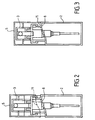
- Ramps 8 and 11 are able to come into contact over part of their length ( figure 1 ) when the cover 5 is in an angular position adapted relative to the container 2, the cover 5 being in the rest position, that is to say that it is not pressed towards the container 2, as will be described in detail later.
- Ramps 8 and 11 are able to define between them and over their entire length a sufficient space ( figure 2 ) to allow the actuation of the dispensing member 4, when the cover 5 is in an angular position adapted relative to the container 2, the cover 5 being in the rest position, as will be described in detail below.
- said ramp 11 has a shape complementary to the ramp 8 so that the two ramps 8 and 11 are able to come into contact along their entire length.
- a hollow stem 16 ( figure 4 ), which is arranged perpendicularly to the axis A, through the dispensing orifice 14.
- Said rod 16 has a diameter equal to the diameter of the orifice 14 and is fixed rigidly to the orifice 14.
- Said rod 16 has a length such that one of the ends 16a of the rod is in contact with the opening 13 and the other end 16b of the rod 16 is fixed to an outlet tube 17, which is arranged vertically in the center of the bottle 1.
- Said tube 17 has for example a diameter substantially equal to the diameter of the rod 16 and has an orifice 17a at the end 16b.
- the end 17b of the tube 17 is fixed rigidly to the pusher 3.
- the other end 17c of the tube 17 is inserted into the dispensing member 4.
- the tube 17 may for example comprise three channels converging at a point d 'intersection. The point of intersection is located in the tube 17, for example near the dispensing orifice 14. When a dose of product is ejected by the dispensing member 4 and it arrives through the three channels at the point of intersection there is a burst of particles that allows the product to vaporize.
- the dispensing member 4 which is here a pump or a valve, comprises a pump body 18 which is placed in the container 2.
- the pump 4 comprises a piston (not shown) which is able to slide in the pump body 18.
- the ring 10 ensures a good seal of the device.
- the ring 10 is further intended to maintain the dispensing member 4 and fix it in the opening of the container 2. This is a conventional fixing ring.
- the ring 10 is for example crimped on the neck 7. When the ring 10 is crimped, the ring 9 prevents a vertical translation upwardly of the ring 10 relative to the container 2.
- the ring 10 comprises a sleeve 22, the lower edge is disposed at the inner periphery of the ring of the ring 10.
- the sleeve 22 is frictionally engaged on the tube 17.
- the sleeve 22 further allows the guiding of the tube 17 during a translation of the tube 17 along the axis A.
- the height of the sleeve 22 is such that the upper edge of the sleeve 22 is substantially at the lower edge of the pusher 3 when the pusher 3 is in the rest position, that is to say when no pressure is exercised on him.
- the outside diameter of the sleeve 22 is such that the sleeve 22 is able to be inserted with friction into the skirt of the pusher 3.
- the sleeve 22 furthermore makes it possible to guide the pusher 3 during a vertical translation of the pusher 3 by relative to the container 2.
- the vaporizer comprises a guide ring 24.
- the ring 24 is able to guide the pusher 3, in cooperation with the ring 10, during a vertical translation.
- the ring 24 is able to guide the cover 5 during a vertical translation.
- the ring 24 is able to limit the vertical translation of the cover 5 towards the container 2 in cooperation with the ring 12.
- the ring 24 has the shape of a sleeve and is inserted on the fixing ring 10 and on the neck 7
- the ring 24 is integral with the ring 10 and the neck 7.
- the lower edge of the ring 24 follows the ramp 8.
- the upper edge of the ring is orthogonal to the axis A and is substantially at the height of the lower edge of the pusher 3, when the pusher 3 is in the rest position.
- the inside diameter of the ring 24 is not constant, so that the inner surface of the ring 24 is, on its lower part, resting on the neck 7, on its central part, resting on the ring 10 and on its upper part that there exists a space 25 between the ring 24 and the sleeve 22.
- the space 25 between the ring 24 and the sleeve 22 has the shape of a well, the width of which is such that the pusher 3 is able to slide between the ring 24 and the sleeve 22, for example during a dispensing operation.
- the outer diameter of the ring 24 is constant and such that the cover 5 can slide on the ring 24 with friction.
- the difference between the ramps 8 and 11 in the rest position of the cover 5, which also corresponds to the difference between ring 12 and the upper edge of the ring 24 in the rest position of the cover 5, may for example correspond to the stroke of the piston.
- This translation has the effect of driving the tube 17 into the body of the pump 18.
- the translation of the tube 17 actuates the pump 4, which has the effect of discharging a dose of product through the tube 17 to the dispensing orifice 14 then to the opening 13, in a conventional manner.
- the guide ring and the sealing ring are constituted by a single piece 124.
- the single piece 124 is for example obtained by molding.
- the ramps 8 and 11 may be of complementary and oval shape, the axis of the largest diameter of each ramp forming an angle ⁇ with the axis A and the angle ⁇ being different from 90 °.
- the ramps 8 and 11 may furthermore not be of complementary shape, the ramp 8 may for example have an oval shape and the ramp 11 may have a sinusoidal shape
- the ring 12 projecting and the groove 15 may be replaced by a fastening system located on the top of the pusher 3, said fastening system for rotating the cover 5 relative to said pusher 3.
- Said fastening system being adapted to ensure the rotation of the cover 5 relative to the pusher 3, the solidarity of the cover 5 and the pusher 3 during a translation of the cover 5 towards the container 2 and allowing the cover 5 to be removed from the device, for example for a filling operation of the container 2.
- the neck 7 may comprise a thread and the ring 10 may be adapted to be screwed onto the neck 7.
- the dispensing member and the outlet channel may be of any type and shape, so as to allow the distribution of the product in different forms.
- the invention is not limited to the embodiments described above. It applies to any type of liquid or pasty product dispenser, regardless of the particular form of the product jet delivered, since it comprises the actuating device by cooperation of ramps respectively integral with the cover and the container.
Description
- La présente invention a pour objet un dispositif de distribution d'un produit fluide ou pâteux, comportant un système de sécurité.
- Des dispositifs de distribution sont fréquemment utilisés dans le domaine de la parfumerie, de la cosmétique ou encore de la pharmacie pour distribuer des produits fluides ou pâteux par appui manuel à l'aide d'un doigt sur un poussoir. Pour des raisons de sécurité, il est souhaitable de pouvoir bloquer l'organe de distribution en position fermée, pour empêcher un actionnement non désiré de la valve ou de la pompe. En général, un capot amovible permet de protéger le poussoir lorsque le distributeur n'est pas en cours d'utilisation, mais de tels capots se retirent facilement et ne constituent donc pas une protection fiable pour le vaporisateur. Il est donc souhaitable qu'un utilisateur dispose d'une sécurité efficace et non séparable de l'organe de distribution, permettant de bloquer le dispositif lorsque celui-ci n'est pas utilisé, par exemple pendant un transport.
- On connaît un dispositif de vaporisation comportant un système de sécurité par le document
FR2803543 - On connaît une autre solution par le document
FR2589756 - Toutefois, les moyens prévus pour le blocage du poussoir dans les dispositifs de distribution décrits dans ces deux documents sont relativement complexes et nécessitent l'utilisation de pièces supplémentaires coûteuses et compliquées à réaliser d'un point de vue industriel.
- La présente invention a pour but de proposer un nouveau dispositif de distribution qui évite les inconvénients précités, dans lequel le système de sécurité permettant de bloquer l'actionnement de la pompe est plus simple et ne nécessite pas l'utilisation de pièces supplémentaires par rapport à un dispositif de distribution classique.
- A cet effet, l'invention a pour objet un dispositif de distribution d'un produit fluide ou pâteux comportant un organe de distribution fixé à un récipient avec une bague d'étanchéité, ledit organe de distribution étant surmonté par un poussoir susceptible d'être enfoncé pour manoeuvrer ledit organe de distribution, ledit poussoir comportant un orifice de distribution permettant l'éjection de produit lorsque ledit organe de distribution est manoeuvré, et un capot, solidaire dudit poussoir lors d'une translation selon l'axe médian du dispositif de distribution en direction dudit récipient, caractérisé en ce que, ledit capot et ledit récipient comportent chacun une rampe, lesdites rampes étant mobiles en rotation l'une par rapport à l'autre entre une position de distribution dans laquelle l'organe de distribution peut être actionné et une position de blocage dans laquelle elles empêchent l'actionnement dudit organe de distribution.
- Avantageusement, lesdites rampes ont une forme complémentaire.
- De préférence, lesdites rampes ont une forme sinusoïdale.
- Selon une caractéristique de l'invention, ledit capot et ledit poussoir sont solidaires en translation.
- Selon une autre caractéristique de l'invention, ledit capot comporte un anneau en saillie intérieure et que ledit poussoir comporte une rainure annulaire, le bord radial intérieur dudit anneau étant logé dans ladite rainure annulaire.
- Avantageusement, ledit dispositif de distribution comporte une bague de guidage, ladite bague de guidage étant apte à coopérer avec ledit poussoir pour le guider, en coopération avec la bague d'étanchéité lors d'une translation, selon l'axe médian du dispositif de distribution, dudit poussoir.
- Selon une autre caractéristique de l'invention, ladite bague de guidage est apte à coopérer avec ledit capot pour le guider lors d'une translation selon l'axe médian du dispositif de distribution.
- De préférence, ladite bague de guidage est apte à coopérer avec ledit capot pour limiter, en coopération avec ledit anneau en saillie, le mouvement de translation du capot vers le récipient.
- Avantageusement, le bord inférieur de ladite bague de guidage a sensiblement la forme de la rampe du récipient et le bord supérieur de ladite bague de guidage a une section circulaire orthogonale à l'axe médian du dispositif de distribution.
- Selon un mode de réalisation de l'invention, la bague de guidage et la bague d'étanchéité sont constituées par une pièce unique.
- Le dispositif de distribution selon la présente invention peut être, par exemple, un vaporisateur. Cependant, le dispositif de distribution peut être adapté pour permettre la distribution d'un produit fluide ou pâteux sous une forme quelconque, par exemple sous forme de goutte, de jet ou de noisette de produit.
- Selon un mode de réalisation particulier de l'invention, en vue de réaliser une vaporisation, ledit dispositif de distribution comporte un tube de sortie destiné à relier ledit organe de distribution et ledit orifice de distribution, ledit tube de sortie comportant au moins trois canaux convergents en un point d'intersection, ledit point d'intersection étant situé en amont dudit orifice de distribution.
- Selon un autre mode de réalisation de l'invention, en vue de délivrer le produit sous forme de goutte, ledit dispositif de distribution comporte un tube de sortie destiné à relier ledit organe de distribution et ledit orifice de distribution, ledit tube de sortie comportant un canal unique.
- L'invention sera mieux comprise, et d'autre buts, détails, caractéristiques et avantages de celle-ci apparaîtront plus clairement au cours de la description explicative détaillée qui va suivre, de plusieurs modes de réalisation de l'invention donnés à titre d'exemples purement illustratifs et non limitatifs, en référence aux dessins schématiques annexés.
Sur ces dessins : - la
figure 1 est une vue simplifiée frontale et en coupe du dispositif de vaporisation selon l'invention, le dispositif étant en position de blocage ; - la
figure 2 est une vue analogue à lafigure 1 , le dispositif étant en position de distribution ; - la
figure 3 est une vue analogue à lafigure 2 , le poussoir étant appuyé ; - la
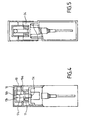
figure 4 est une vue simplifiée latérale et en coupe du dispositif de vaporisation, le dispositif étant en position de blocage ; et - la
figure 5 est une vue analogue à lafigure 1 mais montrant une variante de dispositif de vaporisation conforme à l'invention. - En se référant à la
figure 1 , on voit un dispositif de vaporisation, comportant de façon classique un flacon 1, un récipient 2, un poussoir 3, un organe de distribution 4 et un capot 5. - Le récipient 2 est destiné à contenir un produit fluide, tel que du parfum, de l'eau ou un produit pharmaceutique. Le récipient 2 a une forme sensiblement cylindrique. Le récipient 2 comporte un goulot 7. Le bord inférieur du goulot 7 suit une rampe 8.
- La rampe 8 est telle que la hauteur du goulot 7 n'est pas constante sur sa circonférence. La largeur de la rampe 8 est sensiblement égale à la différence entre le rayon du récipient 2 et le rayon du goulot 7.
- L'extrémité 7b du goulot 7 comporte un anneau 9 en saillie extérieure radiale. Ledit anneau 9 étant apte à coopérer avec une bague d'étanchéité 10 d'une manière qui sera décrite en détail plus loin. L'extrémité 7b comporte une ouverture 7c destinée à insérer l'organe de distribution 4 dans le récipient 2.
- Le capot 5 a une forme sensiblement cylindrique. L'extrémité inférieure 5 a du capot 5 définit un orifice de diamètre supérieur au diamètre du goulot 7, de manière que le capot 5 soit apte à s'emboîter sur ledit goulot 7. Dans l'exemple de réalisation représenté, le capot 5 a un diamètre sensiblement égal au diamètre du récipient 2. Le capot 5 présente sur son bord inférieur une rampe 11.
- Le capot 5 présente un anneau 12 en saillie intérieure. Le capot 5 comporte une ouverture 13 (
figure 4 ), par exemple de forme circulaire, ladite ouverture 13 étant apte à coopérer avec le poussoir 3 pour permettre la distribution d'un produit fluide, comme cela sera décrit en détail plus loin. - Le poussoir 3 a une forme sensiblement cylindrique et comporte de manière classique un orifice de distribution 14, par exemple de section circulaire. La surface 3a radialement extérieure du poussoir 3 présente une rainure 15 annulaire. Ladite rainure 15 coopère avec l'anneau 12 de manière que le bord radial intérieur de l'anneau 12 soit encastré dans la rainure 15. La liaison entre la rainure 15 et l'anneau 12 est telle que le capot 5 et le poussoir 3 sont solidaires en translation et que le capot 5 peut tourner par rapport au poussoir 3 selon l'axe A, qui est l'axe médian du dispositif de vaporisation. Une rotation d'axe A du capot 5 par rapport au poussoir 3 entraîne une rotation d'axe A, de même sens et de même angle du capot 5 par rapport au récipient 2.
- Les rampes 8 et 11 sont aptes à venir en contact sur une partie de leur longueur (
figure 1 ) lorsque le capot 5 est dans une position angulaire adaptée par rapport au récipient 2, le capot 5 étant en position de repos, c'est-à-dire qu'il n'est pas appuyé vers le récipient 2, comme cela sera décrit en détail plus loin. Les rampes 8 et 11 sont aptes à définir entre elles et sur toute leur longueur un espace suffisant (figure 2 ) pour permettre l'actionnement de l'organe de distribution 4, lorsque le capot 5 est dans une position angulaire adapté par rapport au récipient 2, le capot 5 étant en position de repos, comme cela sera décrit en détail plus loin. Par exemple, ladite rampe 11 a une forme complémentaire de la rampe 8 de manière que les deux rampes 8 et 11 soient aptes à venir en contact sur toute leur longueur. - Une tige creuse 16 (
figure 4 ), qui est disposée perpendiculairement à l'axe A, traverse l'orifice de distribution 14. Ladite tige 16 a un diamètre égal au diamètre de l'orifice 14 et est fixée rigidement à l'orifice 14. Ladite tige 16 a une longueur telle que l'une des extrémités 16a de la tige est en contact avec l'ouverture 13 et que l'autre extrémité 16b de la tige 16 est fixée à un tube de sortie 17, qui est disposé verticalement au centre du flacon 1. - Ledit tube 17 a par exemple un diamètre sensiblement égal au diamètre de la tige 16 et comporte un orifice 17a au niveau de l'extrémité 16b. L'extrémité 17b du tube 17 est fixée rigidement au poussoir 3. L'autre extrémité 17c du tube 17 est insérée dans l'organe de distribution 4. Le tube 17 peut par exemple comporter trois canaux qui convergent au niveau d'un point d'intersection. Le point d'intersection se situe dans le tube 17, par exemple à proximité de l'orifice de distribution 14. Lorsqu'une dose de produit est éjectée par l'organe de distribution 4 et qu'elle arrive par les trois canaux au niveau du point d'intersection, il se produit un éclatement des particules qui permet la vaporisation du produit.
- L'organe de distribution 4, qui est ici une pompe ou une valve, comprend un corps de pompe 18 qui est placé dans le récipient 2. De manière classique, la pompe 4 comprend un piston (non montré) qui est apte à coulisser dans le corps de pompe 18.
- La bague 10 permet d'assurer une bonne étanchéité du dispositif. La bague 10 a en outre pour but de maintenir l'organe de distribution 4 et de le fixer dans l'ouverture du récipient 2. Il s'agit d'une bague de fixation classique. La bague 10 est par exemple sertie sur le goulot 7. Lorsque la bague 10 est sertie, l'anneau 9 empêche une translation verticale vers le haut de la bague 10 par rapport au récipient 2. La bague 10 comporte un manchon 22, dont le bord inférieur est disposé au niveau de la périphérie intérieure de l'anneau de la bague 10. Le manchon 22 est engagé avec frottement sur le tube 17. Le manchon 22 permet en outre le guidage du tube 17 lors d'une translation du tube 17 selon l'axe A. La hauteur du manchon 22 est telle que le bord supérieur du manchon 22 est sensiblement au niveau du bord inférieur du poussoir 3 lorsque le poussoir 3 est en position de repos, c'est-à-dire lorsque aucune pression n'est exercée sur lui. Le diamètre extérieur du manchon 22 est tel que le manchon 22 est apte à être inséré avec frottement dans la jupe du poussoir 3. Le manchon 22 permet en outre d'assurer le guidage du poussoir 3 lors d'une translation verticale du poussoir 3 par rapport au récipient 2.
- Le vaporisateur comporte une bague de guidage 24. La bague 24 est apte à guider le poussoir 3, en coopération avec la bague 10, lors d'une translation verticale. La bague 24 est apte à guider le capot 5 lors d'une translation verticale. La bague 24 est apte à limiter la translation verticale du capot 5 en direction du récipient 2 en coopération avec l'anneau 12. La bague 24 a la forme d'un manchon et est insérée sur la bague de fixation 10 et sur le goulot 7. La bague 24 est solidaire de la bague 10 et du goulot 7. Le bord inférieur de la bague 24 suit la rampe 8. Le bord supérieur de la bague est orthogonal à l'axe A et se trouve sensiblement à la hauteur du bord inférieur du poussoir 3, lorsque le poussoir 3 est en position de repos. Le diamètre intérieur de la bague 24 n'est pas constant, de manière que la surface intérieure de la bague 24 soit, sur sa partie inférieure, en appui sur le goulot 7, sur sa partie centrale, en appui sur la bague 10 et sur sa partie supérieure qu'il existe un espace 25 entre la bague 24 et le manchon 22. L'espace 25 entre la bague 24 et le manchon 22 a la forme d'un puits, dont la largeur est telle que le poussoir 3 est apte à coulisser entre la bague 24 et le manchon 22, par exemple lors d'une opération de distribution. Le diamètre extérieur de la bague 24 est constant et tel que le capot 5 peut coulisser sur la bague 24 avec frottement.
- On va maintenant décrire le fonctionnement du vaporisateur selon l'invention, en partant d'un état de distribution dudit vaporisateur, qui est représenté sur la
figure 2 , et dans lequel les rampes 8 et 11 ne sont pas en contact l'une avec l'autre. - Dans cet état, lorsqu'un utilisateur appuie sur le capot 5 de manière que ledit capot 5 se translate verticalement vers le récipient 2, l'anneau 12 qui est inséré dans la rainure 15 entraîne le poussoir 3 qui effectue une translation de même direction. La translation maximum que peut effectuer le capot 5 par rapport au récipient 2 correspond à l'écart entre les rampes 8 et 11 en position de repos du capot 5. L'état correspondant aux deux rampes 8 et 11 en contact est représenté sur la
figure 3 . Cet état correspond à un état dans lequel l'anneau 12 est en appui sur le bord supérieur de la bague 24. L'écart entre les rampes 8 et 11 en position de repos du capot 5, qui correspond également à l'écart entre l'anneau 12 et le bord supérieur de la bague 24 en position de repos du capot 5, peut par exemple correspondre à la course du piston. Cette translation a pour effet d'enfoncer le tube 17 dans le corps de la pompe 18. La translation du tube 17 actionne la pompe 4, ce qui a pour effet de refouler une dose de produit à travers le tube 17 jusqu'à l'orifice de distribution 14 puis jusqu'à l'ouverture 13, d'une manière classique. - On va maintenant décrire une opération de blocage du dispositif de vaporisation selon l'invention.
- Lorsqu'en partant de l'état de distribution représenté sur la
figure 2 un utilisateur agit sur le capot 5 de manière que ledit capot 5 effectue une rotation d'axe A et de 180° par rapport audit récipient 2, les rampes 8 et 11 se disposent l'une par rapport à l'autre de telle manière qu'elles sont en contact sur une partie de leur longueur, en position de repos du capot 5. Le dispositif est en position de blocage. Cette position est représentée sur lafigure 1 et sur lafigure 4 . - Lorsque dans cette position un utilisateur essaye d'appuyer sur le capot 5, le contact entre les rampes 8 et 11 empêche la translation dudit capot 5 et donc dudit poussoir 3, la pompe 4 ne peut donc pas être actionnée. Lorsqu'en partant de l'état de blocage un utilisateur effectue la même opération, c'est-à-dire une rotation de 180° du capot 5 par rapport au récipient 2, les rampes 8 et 11 sont de nouveau mobiles en translation l'une par rapport à l'autre. Le système est en position de distribution.
- En se reportant à la
figure 5 , on voit une variante de réalisation du vaporisateur selon l'invention. La bague de guidage et la bague d'étanchéité sont constituées par une pièce unique 124. La pièce unique 124 est par exemple obtenue par moulage. - D'autres variantes du dispositif de vaporisation, non représentées, sont possibles.
- Par exemple, les rampes 8 et 11 peuvent être de forme complémentaire et ovale, l'axe du plus grand diamètre de chaque rampe faisant un angle α avec l'axe A et l'angle α étant différent de 90°.
- Les rampes 8 et 11 peuvent en outre ne pas être de forme complémentaire, la rampe 8 peut par exemple avoir une forme ovale et la rampe 11 une forme sinusoïdale
- En outre, l'anneau 12 en saillie et la rainure 15 peuvent être remplacés par un système de fixation situé sur le sommet du poussoir 3, ledit système de fixation permettant la rotation du capot 5 par rapport audit poussoir 3. Ledit système de fixation étant apte à assurer le guidage en rotation du capot 5 par rapport au poussoir 3, la solidarité du capot 5 et du poussoir 3 lors d'une translation du capot 5 en direction du récipient 2 et permettant au capot 5 d'être retiré du dispositif, par exemple pour une opération de remplissage du récipient 2.
- Par exemple, le goulot 7 peut comporter un filetage et la bague 10 peut être apte à être vissée sur le goulot 7.
- Pour distribuer un produit pâteux, tel qu'une crème, on peut par exemple remplacer les trois canaux convergents par un canal unique. Dans ce cas il n'y a pas d'éclatement des particules et le dispositif peut permettre de distribuer une noisette de produit. De manière générale, l'organe de distribution et le canal de sortie peuvent être de type et de forme quelconque, de manière à permettre la distribution du produit sous différentes formes.
- L'invention n'est pas limitée aux modes de réalisation ci-dessus décrits. Elle s'applique à tout type de distributeur de produit liquide ou pâteux, indépendamment de la forme particulière du jet de produit délivré, dès lors qu'il comporte le dispositif d'actionnement par coopération de rampes respectivement solidaires du capot et du récipient.
Claims (12)
- Dispositif de distribution d'un produit fluide ou pâteux comportant un organe de distribution (4) fixé à un récipient (2) avec une bague d'étanchéité (10), ledit récipient (2) comportant un goulot (7), ledit organe de distribution (4) étant surmonté par un poussoir (3) susceptible d'être enfoncé pour manoeuvrer ledit organe de distribution (4), ledit poussoir comportant un orifice de distribution (14) permettant l'éjection d'un produit lorsque ledit organe de distribution (4) est manoeuvré, et un capot (5), solidaire dudit poussoir (3) lors d'une translation selon l'axe médian du dispositif de distribution en direction dudit récipient (2), caractérisé en ce qu'un bord dudit goulot (7) comporte une rampe (8), un bord du capot (5) comportant une rampe (11), lesdites rampes (8 et 11) étant mobiles en rotation l'une par rapport à l'autre entre une position de distribution dans laquelle l'organe de distribution (4) peut être actionné et une position de blocage dans laquelle elles empêchent l'actionnement dudit organe de distribution (4).
- Dispositif de distribution selon la revendication 1, caractérisé en ce lesdites rampes (8 et 11) ont une forme complémentaire.
- Dispositif de distribution selon l'une quelconque des revendications 1 ou 2, caractérisé en ce que lesdites rampes (8 et 11) ont une forme sinusoïdale.
- Dispositif de distribution selon l'une quelconque des revendications 1 à 3, caractérisé en ce que ledit capot (5) et ledit poussoir (3) sont solidaires en translation.
- Dispositif de distribution selon l'une quelconque des revendication 1 à 4, caractérisé en ce que ledit capot (5) comporte un anneau (12) en saillie intérieure et que ledit poussoir (3) comporte une rainure (15) annulaire, le bord radial intérieur dudit anneau (12) étant logé dans ladite rainure (15) annulaire.
- Dispositif de distribution selon l'une quelconque des revendications 1 à 5, caractérisé en ce que ledit dispositif de distribution comporte une bague de guidage (24), ladite bague de guidage (24) étant apte à coopérer avec ledit poussoir (3) pour le guider, en coopération avec la bague d'étanchéité (10) lors d'une translation, selon l'axe médian (A) du dispositif de distribution, dudit poussoir (3).
- Dispositif de distribution selon la revendication 6, caractérisé en ce que ladite bague de guidage (24) est apte à coopérer avec ledit capot (5) pour le guider lors d'une translation selon l'axe médian (A) du dispositif de distribution.
- Dispositif de distribution selon la revendication 6, caractérisé en ce que ladite bague de guidage (24) est apte à coopérer avec ledit capot (5) pour limiter, en coopération avec ledit anneau (12) en saillie, le mouvement de translation du capot (5) vers le récipient (2).
- Dispositif de distribution selon la revendication 6, caractérisé en ce que le bord inférieur de ladite bague de guidage (24) a sensiblement la forme de la rampe (8) du récipient (2) et que le bord supérieur de ladite bague de guidage (24) a une section circulaire orthogonale à l'axe médian du dispositif de distribution.
- Dispositif de distribution selon la revendication 6, caractérisé en ce que la bague de guidage (24) et la bague d'étanchéité (10) sont constituées par une pièce unique.
- Dispositif de distribution selon l'une quelconque des revendication 1 à 10, caractérisé en ce que ledit dispositif de distribution comporte un tube de sortie (17) destiné à relier ledit organe de distribution (4) et ledit orifice de distribution (14), ledit tube de sortie (17) comportant au moins trois canaux convergents en un point d'intersection, ledit point d'intersection étant situé en amont dudit orifice de distribution (14).
- Dispositif de distribution selon l'une quelconque des revendications 1 à 10, caractérisé en ce que ledit dispositif de distribution comporte un tube de sortie (17) destiné à relier ledit organe de distribution (4) et ledit orifice de distribution (14), ledit tube de sortie (17) étant constitué par un canal unique.
Applications Claiming Priority (2)
| Application Number | Priority Date | Filing Date | Title |
|---|---|---|---|
| FR0413329A FR2879173B1 (fr) | 2004-12-15 | 2004-12-15 | Dispositif de distribution |
| PCT/FR2005/003134 WO2006064128A1 (fr) | 2004-12-15 | 2005-12-14 | Dispositif de distribution d’un produit fluide ou pâteux |
Publications (2)
| Publication Number | Publication Date |
|---|---|
| EP1828021A1 EP1828021A1 (fr) | 2007-09-05 |
| EP1828021B1 true EP1828021B1 (fr) | 2008-03-26 |
Family
ID=36090986
Family Applications (1)
| Application Number | Title | Priority Date | Filing Date |
|---|---|---|---|
| EP05826571A Active EP1828021B1 (fr) | 2004-12-15 | 2005-12-14 | Dispositif de distribution d'un produit fluide ou pâteux |
Country Status (12)
| Country | Link |
|---|---|
| US (1) | US7882984B2 (fr) |
| EP (1) | EP1828021B1 (fr) |
| JP (1) | JP4974008B2 (fr) |
| CN (1) | CN101094796B (fr) |
| AT (1) | ATE390370T1 (fr) |
| BR (1) | BRPI0519112A2 (fr) |
| CA (1) | CA2590677A1 (fr) |
| DE (1) | DE602005005719T2 (fr) |
| ES (1) | ES2304737T3 (fr) |
| FR (1) | FR2879173B1 (fr) |
| MX (1) | MX2007007166A (fr) |
| WO (1) | WO2006064128A1 (fr) |
Families Citing this family (4)
| Publication number | Priority date | Publication date | Assignee | Title |
|---|---|---|---|---|
| FR2908116B1 (fr) * | 2006-11-06 | 2012-07-13 | Valois Sas | Distributeur de produit fluide |
| US20110289890A1 (en) * | 2010-05-27 | 2011-12-01 | Brian Lee Floyd | Product Dispensing Device |
| US9144818B2 (en) * | 2013-03-13 | 2015-09-29 | Illinois Tool Works Inc. | Method and apparatus for dispensing a viscous material on a substrate |
| IT201800002991A1 (it) * | 2018-02-23 | 2019-08-23 | Guala Dispensing Spa | Dispositivo di erogazione per prodotti pastosi, quali paste dentifricie |
Family Cites Families (19)
| Publication number | Priority date | Publication date | Assignee | Title |
|---|---|---|---|---|
| US2752066A (en) * | 1953-11-09 | 1956-06-26 | Oil Equipment Lab Inc | Combined dispenser and valve operating mechanism |
| US3062411A (en) * | 1959-05-29 | 1962-11-06 | Colgate Pahnolive Company | Dispensing valve actuator |
| US3050219A (en) * | 1959-05-29 | 1962-08-21 | Valve Corp Of America Inc | Locking cap dispensers |
| US3474939A (en) * | 1967-03-15 | 1969-10-28 | Valve Corp Of America | Rotate-to-lock actuator cap for dispensers |
| FR1603803A (fr) * | 1968-07-08 | 1971-06-07 | ||
| US3632024A (en) * | 1970-03-04 | 1972-01-04 | Union Carbide Corp | Aerosol actuator assembly having an actuator button that is rotatable between dispensing and nondispensing positions |
| BE795375A (fr) * | 1972-02-14 | 1973-08-13 | Thiokol Chemical Corp | Atomiseur |
| US3844448A (en) * | 1972-04-27 | 1974-10-29 | J Sette | Valve actuating safety cap assembly for pressurized dispensers |
| US3915354A (en) * | 1974-09-06 | 1975-10-28 | Johnson & Son Inc S C | Automatic relocking device |
| JPH055974Y2 (fr) * | 1987-06-10 | 1993-02-16 | ||
| FR2644432B2 (fr) * | 1988-05-11 | 1991-06-14 | Morel Simone | Capsule a enveloppe tournante pour flacons et recipients analogues |
| GB2238088A (en) * | 1989-11-01 | 1991-05-22 | Hornbeam Ivy Ltd | Liquid dispenser with collar to prevent operation at certain orientations of delivery tube |
| US5070611A (en) * | 1990-11-27 | 1991-12-10 | Stephen Derin | Razor and dispenser |
| US5388730A (en) * | 1993-11-10 | 1995-02-14 | Enviro Pac International L.L.C. | Lockable actuator for a dispensing canister |
| US5957337A (en) * | 1997-08-15 | 1999-09-28 | Bettison, Jr.; William L. | Child resistant aerosol spray apparatus |
| FR2767799B1 (fr) * | 1997-08-27 | 2000-05-12 | Oreal | Ensemble de conditionnement d'un produit liquide ou semi-liquide |
| WO2000066459A1 (fr) * | 1999-04-30 | 2000-11-09 | Coty, Inc. | Capuchon d'atomiseur |
| DE19927381A1 (de) * | 1999-05-04 | 2000-11-16 | Thomas Gmbh | Sprühdose |
| FR2823845B1 (fr) * | 2001-04-20 | 2003-10-31 | Rexam Sofab | Dispositif pour le dosage de produits liquides ou en gel |
-
2004
- 2004-12-15 FR FR0413329A patent/FR2879173B1/fr not_active Expired - Fee Related
-
2005
- 2005-12-14 WO PCT/FR2005/003134 patent/WO2006064128A1/fr active IP Right Grant
- 2005-12-14 DE DE602005005719T patent/DE602005005719T2/de active Active
- 2005-12-14 MX MX2007007166A patent/MX2007007166A/es active IP Right Grant
- 2005-12-14 JP JP2007546114A patent/JP4974008B2/ja not_active Expired - Fee Related
- 2005-12-14 EP EP05826571A patent/EP1828021B1/fr active Active
- 2005-12-14 ES ES05826571T patent/ES2304737T3/es active Active
- 2005-12-14 US US11/721,514 patent/US7882984B2/en not_active Expired - Fee Related
- 2005-12-14 BR BRPI0519112-2A patent/BRPI0519112A2/pt not_active IP Right Cessation
- 2005-12-14 CN CN2005800431162A patent/CN101094796B/zh not_active Expired - Fee Related
- 2005-12-14 CA CA002590677A patent/CA2590677A1/fr not_active Abandoned
- 2005-12-14 AT AT05826571T patent/ATE390370T1/de not_active IP Right Cessation
Also Published As
| Publication number | Publication date |
|---|---|
| BRPI0519112A2 (pt) | 2008-12-23 |
| US20090188942A1 (en) | 2009-07-30 |
| DE602005005719D1 (de) | 2008-05-08 |
| ATE390370T1 (de) | 2008-04-15 |
| ES2304737T3 (es) | 2008-10-16 |
| MX2007007166A (es) | 2007-12-12 |
| DE602005005719T2 (de) | 2009-04-09 |
| WO2006064128A1 (fr) | 2006-06-22 |
| CA2590677A1 (fr) | 2006-06-22 |
| JP4974008B2 (ja) | 2012-07-11 |
| EP1828021A1 (fr) | 2007-09-05 |
| FR2879173A1 (fr) | 2006-06-16 |
| US7882984B2 (en) | 2011-02-08 |
| JP2008523864A (ja) | 2008-07-10 |
| CN101094796A (zh) | 2007-12-26 |
| FR2879173B1 (fr) | 2009-12-11 |
| CN101094796B (zh) | 2010-12-22 |
Similar Documents
| Publication | Publication Date | Title |
|---|---|---|
| EP0591365B1 (fr) | Dispositif pour projeter une dose predeterminee d'un produit fluide, et son procede de remplissage | |
| EP0694483B1 (fr) | Récipient permettant le stockage d'au moins deux produits, le mélange de ces produits et la distribution du mélange ainsi obtenu | |
| EP1044893B1 (fr) | Dispositif pour le mélange extemporané d'au moins deux produits dont un est notamment une poudre | |
| EP0509863B1 (fr) | Dispositif de pulvérisation ou de distribution de produit fluide, à sécurité d'actionnement améliorée | |
| EP0410858A2 (fr) | Ensemble de distribution d'au moins un produit fluide, notamment cosmétique ou pharmaceutique | |
| CH650212A5 (fr) | Dispositif distributeur doseur. | |
| FR2654078A1 (fr) | Obturateur du canal de sortie d'une tete de distribution pour produits pateux et tete de distribution avantageusement associee. | |
| WO1995025945A1 (fr) | Dispositif doseur destine a delivrer des doses unitaires constantes | |
| EP1100625A1 (fr) | Pulverisateur de liquide | |
| EP0335763B1 (fr) | Dispositif pour la distribution d'un mélange de substance pateuse et d'au moins un additif, notamment sous forme de cordon strié, et tête de distribution d'un tel dispositif | |
| EP0278828A1 (fr) | Récipient pour le conditionnement d'un produit et sa distribution controlée comportant un applicateur du type "brosse" | |
| EP1293439B1 (fr) | Dispositif de conditionnement et de distribution d'un produit liquid | |
| EP1828021B1 (fr) | Dispositif de distribution d'un produit fluide ou pâteux | |
| EP1472007B1 (fr) | Distributeur de produit liquide a pompe | |
| EP1379442B1 (fr) | Dispositif pour le dosage de produits liquides ou en gel | |
| EP1412093B1 (fr) | Distributeur de produit liquide ou en gel formant baton doseur | |
| FR2621897A1 (fr) | Distributeur automatique de produits pateux | |
| WO2020234543A1 (fr) | Dispositif de distribution de boisson | |
| FR2857343A1 (fr) | Tete de distribution de produit fluide | |
| FR2742138A1 (fr) | Distributeur de liquide | |
| FR2509980A1 (fr) | Dispositif distributeur doseur | |
| WO2019162597A1 (fr) | Distributeur de produit fluide | |
| FR2678906A1 (fr) | Dispositif pour projeter une dose predeterminee d'un produit fluide, et son procede de remplissage. | |
| FR2593142A1 (fr) | Dispositif distributeur doseur. | |
| FR2512787A1 (fr) | Recipient a piston distributeur et doseur pour produits pateux et/ou mousseux et/ou liquides et/ou poudreux |
Legal Events
| Date | Code | Title | Description |
|---|---|---|---|
| PUAI | Public reference made under article 153(3) epc to a published international application that has entered the european phase |
Free format text: ORIGINAL CODE: 0009012 |
|
| 17P | Request for examination filed |
Effective date: 20070612 |
|
| AK | Designated contracting states |
Kind code of ref document: A1 Designated state(s): AT BE BG CH CY CZ DE DK EE ES FI FR GB GR HU IE IS IT LI LT LU LV MC NL PL PT RO SE SI SK TR |
|
| AX | Request for extension of the european patent |
Extension state: AL BA HR MK YU |
|
| GRAP | Despatch of communication of intention to grant a patent |
Free format text: ORIGINAL CODE: EPIDOSNIGR1 |
|
| RIN1 | Information on inventor provided before grant (corrected) |
Inventor name: FONTAINE, LAURENT Inventor name: FRANCOIS, CEDRIC |
|
| RIN1 | Information on inventor provided before grant (corrected) |
Inventor name: FONTAINE, LAURENT Inventor name: FRANCOIS, CEDRIC |
|
| GRAS | Grant fee paid |
Free format text: ORIGINAL CODE: EPIDOSNIGR3 |
|
| GRAA | (expected) grant |
Free format text: ORIGINAL CODE: 0009210 |
|
| AK | Designated contracting states |
Kind code of ref document: B1 Designated state(s): AT BE BG CH CY CZ DE DK EE ES FI FR GB GR HU IE IS IT LI LT LU LV MC NL PL PT RO SE SI SK TR |
|
| AX | Request for extension of the european patent |
Extension state: AL BA HR MK YU |
|
| REG | Reference to a national code |
Ref country code: GB Ref legal event code: FG4D Free format text: NOT ENGLISH |
|
| REG | Reference to a national code |
Ref country code: IE Ref legal event code: FG4D Free format text: LANGUAGE OF EP DOCUMENT: FRENCH Ref country code: CH Ref legal event code: EP |
|
| REF | Corresponds to: |
Ref document number: 602005005719 Country of ref document: DE Date of ref document: 20080508 Kind code of ref document: P |
|
| RAP2 | Party data changed (patent owner data changed or rights of a patent transferred) |
Owner name: NOUVEL OEUVRE |
|
| PG25 | Lapsed in a contracting state [announced via postgrant information from national office to epo] |
Ref country code: FI Free format text: LAPSE BECAUSE OF FAILURE TO SUBMIT A TRANSLATION OF THE DESCRIPTION OR TO PAY THE FEE WITHIN THE PRESCRIBED TIME-LIMIT Effective date: 20080326 |
|
| PG25 | Lapsed in a contracting state [announced via postgrant information from national office to epo] |
Ref country code: AT Free format text: LAPSE BECAUSE OF FAILURE TO SUBMIT A TRANSLATION OF THE DESCRIPTION OR TO PAY THE FEE WITHIN THE PRESCRIBED TIME-LIMIT Effective date: 20080326 |
|
| NLV1 | Nl: lapsed or annulled due to failure to fulfill the requirements of art. 29p and 29m of the patents act | ||
| PG25 | Lapsed in a contracting state [announced via postgrant information from national office to epo] |
Ref country code: PL Free format text: LAPSE BECAUSE OF FAILURE TO SUBMIT A TRANSLATION OF THE DESCRIPTION OR TO PAY THE FEE WITHIN THE PRESCRIBED TIME-LIMIT Effective date: 20080326 Ref country code: LV Free format text: LAPSE BECAUSE OF FAILURE TO SUBMIT A TRANSLATION OF THE DESCRIPTION OR TO PAY THE FEE WITHIN THE PRESCRIBED TIME-LIMIT Effective date: 20080326 Ref country code: SI Free format text: LAPSE BECAUSE OF FAILURE TO SUBMIT A TRANSLATION OF THE DESCRIPTION OR TO PAY THE FEE WITHIN THE PRESCRIBED TIME-LIMIT Effective date: 20080326 |
|
| REG | Reference to a national code |
Ref country code: ES Ref legal event code: FG2A Ref document number: 2304737 Country of ref document: ES Kind code of ref document: T3 |
|
| REG | Reference to a national code |
Ref country code: IE Ref legal event code: FD4D |
|
| PG25 | Lapsed in a contracting state [announced via postgrant information from national office to epo] |
Ref country code: CZ Free format text: LAPSE BECAUSE OF FAILURE TO SUBMIT A TRANSLATION OF THE DESCRIPTION OR TO PAY THE FEE WITHIN THE PRESCRIBED TIME-LIMIT Effective date: 20080326 Ref country code: PT Free format text: LAPSE BECAUSE OF FAILURE TO SUBMIT A TRANSLATION OF THE DESCRIPTION OR TO PAY THE FEE WITHIN THE PRESCRIBED TIME-LIMIT Effective date: 20080901 Ref country code: SE Free format text: LAPSE BECAUSE OF FAILURE TO SUBMIT A TRANSLATION OF THE DESCRIPTION OR TO PAY THE FEE WITHIN THE PRESCRIBED TIME-LIMIT Effective date: 20080626 Ref country code: SK Free format text: LAPSE BECAUSE OF FAILURE TO SUBMIT A TRANSLATION OF THE DESCRIPTION OR TO PAY THE FEE WITHIN THE PRESCRIBED TIME-LIMIT Effective date: 20080326 |
|
| PG25 | Lapsed in a contracting state [announced via postgrant information from national office to epo] |
Ref country code: RO Free format text: LAPSE BECAUSE OF FAILURE TO SUBMIT A TRANSLATION OF THE DESCRIPTION OR TO PAY THE FEE WITHIN THE PRESCRIBED TIME-LIMIT Effective date: 20080326 Ref country code: NL Free format text: LAPSE BECAUSE OF FAILURE TO SUBMIT A TRANSLATION OF THE DESCRIPTION OR TO PAY THE FEE WITHIN THE PRESCRIBED TIME-LIMIT Effective date: 20080326 |
|
| PG25 | Lapsed in a contracting state [announced via postgrant information from national office to epo] |
Ref country code: IS Free format text: LAPSE BECAUSE OF FAILURE TO SUBMIT A TRANSLATION OF THE DESCRIPTION OR TO PAY THE FEE WITHIN THE PRESCRIBED TIME-LIMIT Effective date: 20080726 |
|
| PG25 | Lapsed in a contracting state [announced via postgrant information from national office to epo] |
Ref country code: LT Free format text: LAPSE BECAUSE OF FAILURE TO SUBMIT A TRANSLATION OF THE DESCRIPTION OR TO PAY THE FEE WITHIN THE PRESCRIBED TIME-LIMIT Effective date: 20080326 Ref country code: IE Free format text: LAPSE BECAUSE OF FAILURE TO SUBMIT A TRANSLATION OF THE DESCRIPTION OR TO PAY THE FEE WITHIN THE PRESCRIBED TIME-LIMIT Effective date: 20080326 Ref country code: DK Free format text: LAPSE BECAUSE OF FAILURE TO SUBMIT A TRANSLATION OF THE DESCRIPTION OR TO PAY THE FEE WITHIN THE PRESCRIBED TIME-LIMIT Effective date: 20080326 |
|
| PLBE | No opposition filed within time limit |
Free format text: ORIGINAL CODE: 0009261 |
|
| STAA | Information on the status of an ep patent application or granted ep patent |
Free format text: STATUS: NO OPPOSITION FILED WITHIN TIME LIMIT |
|
| 26N | No opposition filed |
Effective date: 20081230 |
|
| PG25 | Lapsed in a contracting state [announced via postgrant information from national office to epo] |
Ref country code: BG Free format text: LAPSE BECAUSE OF FAILURE TO SUBMIT A TRANSLATION OF THE DESCRIPTION OR TO PAY THE FEE WITHIN THE PRESCRIBED TIME-LIMIT Effective date: 20080626 Ref country code: EE Free format text: LAPSE BECAUSE OF FAILURE TO SUBMIT A TRANSLATION OF THE DESCRIPTION OR TO PAY THE FEE WITHIN THE PRESCRIBED TIME-LIMIT Effective date: 20080326 |
|
| BERE | Be: lapsed |
Owner name: NOUVEL OEUVRE Effective date: 20081231 |
|
| PG25 | Lapsed in a contracting state [announced via postgrant information from national office to epo] |
Ref country code: MC Free format text: LAPSE BECAUSE OF NON-PAYMENT OF DUE FEES Effective date: 20081231 |
|
| PG25 | Lapsed in a contracting state [announced via postgrant information from national office to epo] |
Ref country code: CY Free format text: LAPSE BECAUSE OF FAILURE TO SUBMIT A TRANSLATION OF THE DESCRIPTION OR TO PAY THE FEE WITHIN THE PRESCRIBED TIME-LIMIT Effective date: 20080326 Ref country code: BE Free format text: LAPSE BECAUSE OF NON-PAYMENT OF DUE FEES Effective date: 20081231 |
|
| PG25 | Lapsed in a contracting state [announced via postgrant information from national office to epo] |
Ref country code: HU Free format text: LAPSE BECAUSE OF FAILURE TO SUBMIT A TRANSLATION OF THE DESCRIPTION OR TO PAY THE FEE WITHIN THE PRESCRIBED TIME-LIMIT Effective date: 20080927 Ref country code: LU Free format text: LAPSE BECAUSE OF NON-PAYMENT OF DUE FEES Effective date: 20081214 |
|
| REG | Reference to a national code |
Ref country code: CH Ref legal event code: PL |
|
| PG25 | Lapsed in a contracting state [announced via postgrant information from national office to epo] |
Ref country code: TR Free format text: LAPSE BECAUSE OF FAILURE TO SUBMIT A TRANSLATION OF THE DESCRIPTION OR TO PAY THE FEE WITHIN THE PRESCRIBED TIME-LIMIT Effective date: 20080326 |
|
| REG | Reference to a national code |
Ref country code: CH Ref legal event code: NV Representative=s name: E. BLUM & CO. AG PATENT- UND MARKENANWAELTE VSP Ref country code: CH Ref legal event code: AEN Free format text: LE BREVET A ETE REACTIVE SELON LA DEMANDE DE POURSUITE DE LA PROCEDURE DU 27.09.2010. |
|
| PG25 | Lapsed in a contracting state [announced via postgrant information from national office to epo] |
Ref country code: GR Free format text: LAPSE BECAUSE OF FAILURE TO SUBMIT A TRANSLATION OF THE DESCRIPTION OR TO PAY THE FEE WITHIN THE PRESCRIBED TIME-LIMIT Effective date: 20080627 |
|
| PGFP | Annual fee paid to national office [announced via postgrant information from national office to epo] |
Ref country code: CH Payment date: 20131219 Year of fee payment: 9 Ref country code: GB Payment date: 20131227 Year of fee payment: 9 Ref country code: DE Payment date: 20131230 Year of fee payment: 9 |
|
| PGFP | Annual fee paid to national office [announced via postgrant information from national office to epo] |
Ref country code: ES Payment date: 20131226 Year of fee payment: 9 Ref country code: IT Payment date: 20131228 Year of fee payment: 9 |
|
| REG | Reference to a national code |
Ref country code: DE Ref legal event code: R119 Ref document number: 602005005719 Country of ref document: DE |
|
| REG | Reference to a national code |
Ref country code: CH Ref legal event code: PL |
|
| GBPC | Gb: european patent ceased through non-payment of renewal fee |
Effective date: 20141214 |
|
| PG25 | Lapsed in a contracting state [announced via postgrant information from national office to epo] |
Ref country code: GB Free format text: LAPSE BECAUSE OF NON-PAYMENT OF DUE FEES Effective date: 20141214 Ref country code: CH Free format text: LAPSE BECAUSE OF NON-PAYMENT OF DUE FEES Effective date: 20141231 Ref country code: LI Free format text: LAPSE BECAUSE OF NON-PAYMENT OF DUE FEES Effective date: 20141231 Ref country code: DE Free format text: LAPSE BECAUSE OF NON-PAYMENT OF DUE FEES Effective date: 20150701 |
|
| REG | Reference to a national code |
Ref country code: FR Ref legal event code: PLFP Year of fee payment: 11 |
|
| PG25 | Lapsed in a contracting state [announced via postgrant information from national office to epo] |
Ref country code: IT Free format text: LAPSE BECAUSE OF NON-PAYMENT OF DUE FEES Effective date: 20141214 |
|
| REG | Reference to a national code |
Ref country code: ES Ref legal event code: FD2A Effective date: 20160126 |
|
| PG25 | Lapsed in a contracting state [announced via postgrant information from national office to epo] |
Ref country code: ES Free format text: LAPSE BECAUSE OF NON-PAYMENT OF DUE FEES Effective date: 20141215 |
|
| REG | Reference to a national code |
Ref country code: FR Ref legal event code: PLFP Year of fee payment: 12 |
|
| REG | Reference to a national code |
Ref country code: FR Ref legal event code: PLFP Year of fee payment: 13 |
|
| PGFP | Annual fee paid to national office [announced via postgrant information from national office to epo] |
Ref country code: FR Payment date: 20211227 Year of fee payment: 17 |
|
| PG25 | Lapsed in a contracting state [announced via postgrant information from national office to epo] |
Ref country code: FR Free format text: LAPSE BECAUSE OF NON-PAYMENT OF DUE FEES Effective date: 20221231 |