EP3767185A1 - Filterelement für dunstabzugsvorrichtung und dunstabzugsvorrichtung - Google Patents
Filterelement für dunstabzugsvorrichtung und dunstabzugsvorrichtung Download PDFInfo
- Publication number
- EP3767185A1 EP3767185A1 EP20180830.0A EP20180830A EP3767185A1 EP 3767185 A1 EP3767185 A1 EP 3767185A1 EP 20180830 A EP20180830 A EP 20180830A EP 3767185 A1 EP3767185 A1 EP 3767185A1
- Authority
- EP
- European Patent Office
- Prior art keywords
- filter
- filter element
- cover layer
- reinforcement
- layer
- Prior art date
- Legal status (The legal status is an assumption and is not a legal conclusion. Google has not performed a legal analysis and makes no representation as to the accuracy of the status listed.)
- Granted
Links
Images


Classifications
-
- F—MECHANICAL ENGINEERING; LIGHTING; HEATING; WEAPONS; BLASTING
- F24—HEATING; RANGES; VENTILATING
- F24C—DOMESTIC STOVES OR RANGES ; DETAILS OF DOMESTIC STOVES OR RANGES, OF GENERAL APPLICATION
- F24C15/00—Details
- F24C15/20—Removing cooking fumes
- F24C15/2035—Arrangement or mounting of filters
-
- B—PERFORMING OPERATIONS; TRANSPORTING
- B01—PHYSICAL OR CHEMICAL PROCESSES OR APPARATUS IN GENERAL
- B01D—SEPARATION
- B01D46/00—Filters or filtering processes specially modified for separating dispersed particles from gases or vapours
- B01D46/0002—Casings; Housings; Frame constructions
- B01D46/0005—Mounting of filtering elements within casings, housings or frames
-
- B—PERFORMING OPERATIONS; TRANSPORTING
- B01—PHYSICAL OR CHEMICAL PROCESSES OR APPARATUS IN GENERAL
- B01D—SEPARATION
- B01D46/00—Filters or filtering processes specially modified for separating dispersed particles from gases or vapours
- B01D46/10—Particle separators, e.g. dust precipitators, using filter plates, sheets or pads having plane surfaces
- B01D46/12—Particle separators, e.g. dust precipitators, using filter plates, sheets or pads having plane surfaces in multiple arrangements
Definitions
- the present invention relates to a filter element for an extractor device and an extractor device.
- one or more filter elements are generally arranged in an intake opening in order to filter out the impurities from the incoming air.
- filter cassettes are used that consist of several filter layers made of expanded metal. These filter layers are enclosed in a support frame. These filter elements are also known as grease filters.
- a disadvantage of these filter elements is that, particularly at the transition between expanded metal and support frame, more and more contaminants can settle.
- the visual appearance of the known filter elements is impaired due to the visible transition between the filter layers and the support frame.
- the object of the present invention is therefore to create a filter element which at least reduces the disadvantages of the prior art and which can nonetheless be handled and manufactured easily.
- the invention relates to a filter element for an extractor device with at least two filter layers.
- the filter element is characterized in that the filter element has a cover layer consisting of filter material, which forms the inflow side of the filter element and covers the edges of the filter layers.
- the extractor device is preferably an extractor hood.
- a flat filter element is referred to as a filter element.
- the filter element can be arranged in or in front of the suction opening of the extractor device.
- the filter element has at least two filter layers.
- a layer is used as the filter layer
- Filter material denotes on which at least some of the impurities, in particular fat, can be filtered out of the contaminated air that flows into the filter element.
- the polluted air is also known as steam or vapor.
- the filter element has an inflow side and a clean air side.
- the side on which the contaminated air flows against the filter element in the position arranged in the extractor device is referred to as the upstream side.
- the clean air side is the side through which the cleaned air exits the filter element.
- the clean air side is opposite the inflow side and faces the inside of the extractor device when the filter element is inserted.
- the filter element has at least two filter layers. However, the number of filter layers can also be higher. For example, the filter element can have three or nine layers.
- the at least two filter layers are also referred to below as a stack of filter layers or simply as a stack.
- the invention is not limited to a specific number of filter layers.
- the filter layers can each consist of the same filter material. However, filter layers made of different filter materials can also be used in the filter element.
- at least one filter layer can represent an expanded metal layer and at least one further filter layer can represent a fleece, for example a metal fleece.
- the filter layers are arranged on top of one another in the filter element.
- the filter layer on the clean air side of the filter element is also referred to as the upper filter layer.
- the filter element has a cover layer, which can also be referred to as a cover.
- a layer or layer is called a top layer.
- the top layer forms the upstream side of the filter element, which can also be referred to as the underside.
- the part of the cover layer which forms the inflow side of the filter element is preferably at least partially in contact with the surface of the lower of the plurality of filter layers.
- This part of the top layer is also referred to below as the base area of the top layer.
- the base area of the cover layer is preferably parallel to the filter layers of the filter element.
- the top layer therefore covers the stack of filter layers from below.
- the top layer can consist of a single layer or ply. However, it is also within the scope of the invention that the cover layer consists of several layers or plies.
- the cover layer covers the edges of the filter layers of the filter element.
- the lateral ends of the filter layers are referred to as edges.
- the filter layers preferably have a rectangular shape.
- the cover layer preferably covers all the edges or edges of the filter layers lying on top of one another on the sides.
- the cover layer is preferably bent vertically upwards at the edges of the base area, that is to say bent over in the direction of the filter layers.
- the upwardly bent part of the cover layer forms the lateral outer sides of the filter element.
- the top layer thus surrounds the stack of filter layers from below and from the sides.
- the covering of the edges of the filter layers can be indirect or direct.
- a further element of the filter element can be arranged between the edges of the filter layers or the edges of the filter layers can bear directly on the cover layer.
- Directional information such as above or below relate - unless otherwise stated - to the filter element in the state in which it is arranged at the suction opening in an extractor device with a horizontal suction opening, which is flown against from below.
- the upstream side of the filter element is therefore also referred to as the underside of the filter element and the clean air side as the upper side.
- the top layer consists of filter material.
- both the base area and the part of the cover layer that covers the stack of filter layers on the sides are preferably made of filter material.
- the cover layer preferably consists entirely of filter material.
- cover layer made of filter material according to the invention which forms the inflow side of the filter element and covers the edges of the filter layers of the filter element, a number of advantages can be achieved.
- the upstream side of the filter element is formed by the continuous base area of the cover plate.
- the entire base of the cover plate can serve to deposit and hold impurities.
- a dripping of dirt from a frame, which forms part of the upstream side in the prior art can be prevented.
- the cleaning of the filter element is also simplified compared to the prior art due to the continuous inflow side.
- the optical appearance of the filter element according to the invention is improved compared to the prior art due to the continuous base area of the cover layer, which forms the inflow side.
- the filter element has a reinforcement in the edge area and the cover layer covers the reinforcement.
- Reinforcement is a means by which the stability of the filter element is increased.
- the reinforcement is provided in the edge area.
- the reinforcement is preferably provided along the edges of the filter layers and extends partially inward from the respective edge in the surface direction of the filter layer. Since the reinforcement is covered by the cover layer, the optical appearance can also be kept uniform with a reinforcement.
- the reinforcement can be covered by the cover layer on the sides, thus preventing the risk of injury to the user. Finally, when a reinforcement is provided by a separate element, this can be held by the cover layer and the reinforcement can be prevented from shifting.
- the reinforcement represents an embossing of at least some of the filter layers.
- the edges of the filter layers lying one above the other are connected to one another by embossing.
- a connection that is created by applying pressure is called embossing.
- the edges of the filter layers can be pressed together.
- at least one embossing is provided in the surface of the stack of filter layers; this can extend linearly in the width or depth direction of the stack. If a tool is used as the embossing tool, the surface of which has a contour, the embossed edge of the stack of filter layers can, for example, have a wave shape.
- the stability of the filter element can be increased by embossing at least some of the filter layers and in particular the edges of the filter layers. This reduces the requirements for the material of the cover plate and, for example, a cover layer with a smaller thickness can be used. In this embodiment, both the production and the handling are thus simplified and the optical appearance of the filter element is nevertheless retained due to the cover layer.
- the reinforcement can preferably comprise at least one reinforcement element.
- a reinforcement element is an element that is separate from the filter layers and the cover layer of the filter element and increases the stability of the filter element.
- the reinforcement element can be arranged at least in some areas on or under the stack of filter layers.
- the reinforcing element can also be arranged at least partially between two adjacent filter layers, that is to say lying one on top of the other.
- the reinforcement element can for example consist of metal or plastic.
- the reinforcing element can be made from a magnetizable metal, for example.
- the reinforcement element is preferably arranged in the filter element in such a way that it rests against the edges of the filter elements and / or in the edge region of the surfaces of the filter layers on the filter layers.
- the reinforcing element is at least partially arranged on the edge of the filter layer, which is in the filter element of the upstream side of the Filter element opposite.
- the reinforcing element lies on the edge of the upper filter layer.
- the reinforcing element preferably extends over the entire edge of the upper filter layer.
- the reinforcing element is preferably designed in one piece. This simplifies the manufacture of the filter element and increases the stability of the filter element. Since the reinforcement element is arranged on the upper filter layer, it can be applied to the stack after the stack has been produced and also, for example, after the filter layers of the stack have been embossed. This simplifies production.
- the reinforcement element by arranging the reinforcement element on the upper filter layer, the filter function of the filter layers below can be used over their entire surface, since these are not covered at the bottom by the reinforcement element.
- the reinforcement element is preferably covered at least on the sides by the cover layer.
- the reinforcement element can be held at least in the surface direction of the filter layers and prevented from slipping. A separate attachment of the reinforcement element to the filter layers can be omitted.
- the reinforcement element can represent a frame with a U-shaped, an L-shaped, T-shaped or a flat cross section.
- several reinforcing elements of different shapes can also be provided.
- the filter element can have a frame with a U-shaped cross section and a frame with a flat cross section.
- the reinforcing element represents a frame, this is covered by the cover layer at least on the sides.
- the frames that can be used as reinforcement elements can, for example, be a roll-forming or extrusion profile made of stainless steel or aluminum.
- the open sides of the U-profile face one another.
- At least one filter layer can be accommodated on the edge of the open sides of the U-profile.
- the U-profile comprises all the filter layers on their edges, that is to say the filter layers are received in the U-profile.
- the frame with the U-shaped cross section can also be placed on the upper filter layer.
- the open sides of the U-profile of the frame face each other; the edges of the filter layers are not held by the frame. Rather, in this embodiment, the filter layers and the reinforcing element are only held by the cover layer.
- one leg of the L-profile can be placed on the top of the upper filter layer.
- the second leg can either extend downward along the edges of at least one of the filter layers or extend upward away from the filter layers. It is also possible for the L-profile to be arranged in such a way that one leg is arranged between two adjacent filter layers and the second leg extends upwards or downwards along the edge of at least one further filter layer.
- the main leg of the T-profile can be placed on the upper filter layer.
- One leg extending from the main leg extends upwards and the other leg extending from the main leg extends downward along the edge of at least one filter layer.
- the frame with a T-shaped profile can also be arranged such that the main leg lies between two adjacent filter layers and the two legs extending from the main leg extend upwards and downwards along the edges of the filter layers.
- the reinforcing element is a frame with a flat cross-section
- this can be placed either on the stack of filter layers or under the stack of filter layers.
- the frame can also be arranged between adjacent filter layers.
- a reinforcing element in the form of a frame has is that production is simplified, since this can be installed as a part in the filter element.
- at least some of the filter layers can also be held by the frame.
- the frame will at least be the Sides covered by the top layer.
- the frame is preferably also covered at the top by the cover layer.
- the cover layer therefore has a bevel on the side opposite the inflow side of the filter element, which is directed inward.
- the side opposite the inflow side of the filter element can also be referred to as the clean air side or top of the filter element.
- the fold of the top layer extends inward. This means that the fold is directed towards the filter layers.
- the cover layer From the base of the cover layer, which forms the inflow side of the filter element, the cover layer extends upwards at the edges of the base and thereby forms side surfaces by which the filter layers and any reinforcements provided on the sides are covered.
- the bevel of the cover layer is provided at the upper end of the side surfaces.
- the top layer is an expanded metal layer.
- expanded metal is easy to manufacture and process.
- the required shape of the cover layer with which it forms the inflow side of the filter element and covers the edges of the filter layers and any reinforcements provided on the sides can be produced in a simple manner.
- expanded metal is easy to handle.
- expanded metal can be surface-treated, for example anodized or coated. This can improve the optical properties of the filter element and facilitate its cleaning.
- the filter element has a magnetizable element.
- the magnetizable element is preferably arranged in the upper region of the filter element.
- the magnetizable element can be placed on the upper filter layer and covered from the cover layer upwards by the fold.
- the magnetizable element can, for example, form the reinforcing element.
- the filter element can be releasably attached to the extractor device without the need for a handle Fastening pins extend from one side of the filter element, as is the case in the prior art. This further simplifies the manufacture and use of the filter element.
- the cover layer can also be made from a magnetizable material.
- a magnet is provided on the extractor device, via which the filter element is held.
- a magnet can be provided on the filter element and at least part of the extractor device on the suction opening can be made of a magnetizable material.
- the invention relates to an extractor device which is characterized in that the extractor device has at least one filter element according to the invention.
- the extractor hood device preferably has a suction opening which is inclined in the horizontal, the vertical or between the vertical and the horizontal.
- At least one filter element according to the invention is arranged at the suction opening in such a way that the cover layer and in particular the base area of the cover layer forms the inflow side of the filter element.
- the extractor device comprises at least one magnet on the suction opening.
- the at least one filter element can be held via the at least one magnet and this can be designed without a handle.
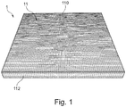
- FIG 1 an embodiment of a filter element 1 according to the invention is shown in a perspective view from below.
- the filter element 1 represents a rectangular filter element 1.
- This upstream side is formed by the base area 110 of a cover layer 11 of the filter element 1.
- the cover layer 11 is formed by an expanded metal layer.
- the cover layer 11 is facing upwards (in Figure 1 down). This forms side surfaces 111 of the cover layer 11 which, in the embodiment shown, extend perpendicular to the base surface 110.
- the filter element 1 has four filter layers 10 in the embodiment shown.
- the filter layers 10 are surrounded by the cover layer 11 at the bottom and to the sides.
- the lower filter layer 10 of the stack of filter layers 10 rests on the cover layer 11.
- This area forms the base area 110 of the cover layer 11.
- the cover layer 11 is bent upwards and forms side surfaces 112 of the cover layer 11.
- the side surfaces 112 cover the edges of the filter layers 10 on the sides.
- a reinforcement 12 in the form of a reinforcement element 120 is arranged on the upper filter layer 10.
- the reinforcement element 120 lies on the edge region of the upper filter layer 10.
- the reinforcement element 120 is in FIG first embodiment according to the Figures 1 to 4 a frame with a U-shaped cross section.
- the base of the U-profile lies on the outer edge of the upper filter layer 10 and the legs are directed inwards.
- the lower leg rests on the upper filter layer 10.
- the side surface 112 of the cover layer 11 has a height which corresponds to the height of the stack of filter layers 10 and the height of the reinforcement element 120.
- the cover layer 11 thus surrounds the filter layers 10 and the reinforcing element 120 on the sides, in particular on the outer edge.
- the cover layer 11 has a bevel 111 at the upper end of the side surface 112.
- the bevel 111 is thus on the upper side of the filter element 1, that is to say on the side facing away from the inflow side in which the base area 110 is located.
- the fold 111 rests on the upper side of the upper limb of the reinforcement element 120. At the free end of the fold 111 this is bent downwards and outwards.
- the cover layer 11 extends around the free end of the upper leg of the reinforcement element 120 and along the underside of the upper leg of the reinforcement element 120 to the outside.
- the end of the cover layer 11 lies inside the reinforcing element 120 and injury to the user when touching the filter element 1 can be prevented.
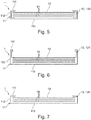
- a second embodiment of the filter element 1 is shown.
- This embodiment differs from the first embodiment only in that the reinforcement element 120 is placed in the form of a U-shaped frame on the base surface 110 of the cover layer 11 and the edges of the filter layers 10 are received in the U-shaped profile.
- the fold over of the free end of the fold 111 of the cover layer 11 is not shown. This envelope can also be provided in the second embodiment.
- a third embodiment of the filter element 1 is shown.
- This embodiment differs from the first embodiment only in that the reinforcement element 120 represents a frame with an L-shaped cross section.
- the lower leg of the frame rests on the upper filter layer 10 in the edge area and the second leg extends from the outermost edge of the upper filter layer 10 upwards.
- the upper end of the second leg is encompassed by the cover layer 11 by a fold 111 and a bend provided at the free end of the fold 111.
- FIG 7 a fourth embodiment of the filter element 1 is shown.
- This embodiment differs from the first embodiment only in that the reinforcing element 120 is a frame with a flat cross section.
- the frame rests on the upper filter layer 10 in the edge area and is covered by the cover layer 11 and in particular a fold 111 upwards.
- FIG 8 a fifth embodiment of the filter element 1 is shown. This embodiment differs from the fourth embodiment only in that the reinforcement element 120 is arranged in the form of the frame with a flat cross section between two filter layers 10.
- FIG. 9 a sixth embodiment of the filter element 1 is shown. This embodiment differs from the fifth embodiment only in that no reinforcing element 120 is provided.
- the reinforcement 12 is formed by an embossing 121.
- the edges of the filter layers 10 are pressed together. These embossed edges are surrounded by the side surfaces 112 of the cover layer 11 and are covered at the top by the bevel 111 of the cover layer 11.
- the present invention thus differs from the prior art.
- expanded metal filters which have a support frame located in the visible area.
- a filter element with frameless optics is produced.
- This preferably also has a reinforcing element. This can be made from different materials.
- the reinforcement element can also be produced in different geometries.
- a frame with a U-profile can be placed on the filter layers made of expanded metal. This creates the opacity on the underside of the filter element, which can also be referred to as the front.
- the frame is covered by the filter layers. Then the top layer is pulled over the frame so that it is not visible.
- expanded metal filter layers a wide variety of other materials, such as special PP mesh, foams, expanded metals or other metal meshes, can be used as the filter and top layer.
- the present invention has a number of advantages.
- a homogeneous filter surface can be achieved without interruption by the frame.
- the costs can be reduced.
- the filter element is easier to clean, since the handle cannot be soiled.
Landscapes
- Chemical & Material Sciences (AREA)
- Chemical Kinetics & Catalysis (AREA)
- Engineering & Computer Science (AREA)
- Combustion & Propulsion (AREA)
- Mechanical Engineering (AREA)
- General Engineering & Computer Science (AREA)
- Filtering Of Dispersed Particles In Gases (AREA)
Abstract
Description
- Die vorliegende Erfindung betrifft ein Filterelement für eine Dunstabzugsvorrichtung und eine Dunstabzugsvorrichtung.
- Bei Dunstabzugsvorrichtungen für die Verwendung in einer Küche, insbesondere Dunstabzugshauben, werden in der Regel ein oder mehrere Filterelemente in einer Ansaugöffnung angeordnet, um die Verunreinigungen aus der anströmenden Luft auszufiltern. Hierbei werden Filterkassetten verwendet, die aus mehreren Filterlagen aus Streckmetall bestehen. Diese Filterlagen sind in einem Trägerrahmen eingefasst. Diese Filterelemente werden auch als Fettfilter bezeichnet.
- Ein Nachteil dieser Filterelemente besteht darin, dass sich insbesondere am Übergang zwischen Streckmetall und Trägerrahmen Verunreinigungen vermehrt absetzen können. Zudem ist das optische Erscheinungsbild der bekannten Filterelemente aufgrund des sichtbaren Übergangs zwischen Filterlagen und Trägerrahmen beeinträchtigt.
- Aufgabe der vorliegenden Erfindung ist es somit ein Filterelement zu schaffen, das die Nachteile des Standes der Technik zumindest verringert und das dennoch einfach gehandhabt und hergestellt werden kann.
- Gemäß einem ersten Aspekt betrifft die Erfindung ein Filterelement für Dunstabzugsvorrichtung mit mindestens zwei Filterlagen. Das Filterelement ist dadurch gekennzeichnet, dass das Filterelement eine Decklage, die aus Filtermaterial besteht, aufweist, die die Anströmseite des Filterelementes bildet und die Ränder der Filterlagen abdeckt.
- Die Dunstabzugsvorrichtung stellt vorzugsweise eine Dunstabzugshaube dar. Als Filterelement wird ein flächiges Filterelement bezeichnet. Das Filterelement kann in der oder vor der Ansaugöffnung der Dunstabzugsvorrichtung angeordnet werden. Das Filterelement weist mindestens zwei Filterlagen auf. Als Filterlage wird eine Schicht aus Filtermaterial bezeichnet, an dem zumindest ein Teil der Verunreinigungen, insbesondere Fett, aus der verunreinigten Luft, die das Filterelement anströmt, ausgefiltert werden kann. Die verunreinigte Luft wird auch als Dünste oder Wrasen bezeichnet. Das Filterelement weist eine Anströmseite und eine Reinluftseite auf. Als Anströmseite wird die Seite bezeichnet, an der das Filterelement in der in der Dunstabzugsvorrichtung angeordneten Position von der verunreinigten Luft angeströmt wird. Als Reinluftseite wird die Seite bezeichnet, über die die gereinigte Luft aus dem Filterelement austritt. Die Reinluftseite liegt der Anströmseite gegenüber und ist im eingebrachten Zustand des Filterelementes der Innenseite der Dunstabzugsvorrichtung zugewandt. Das Filterelement weist mindestens zwei Filterlagen auf. Die Anzahl der Filterlagen kann allerdings auch höher sein. Beispielsweise kann das Filterelement drei oder neun Lagen aufweisen. Die mindestens zwei Filterlagen werden im Folgenden auch als Stapel von Filterlagen oder einfach als Stapel bezeichnet. Die Erfindung ist nicht auf eine bestimmte Anzahl von Filterlagen beschränkt. Die Filterlagen können jeweils aus dem gleichen Filtermaterial bestehen. Allerdings können in dem Filterelement auch Filterlagen aus unterschiedlichem Filtermaterial verwendet werden. Beispielsweise kann mindestens eine Filterlage eine Streckmetalllage darstellen und mindestens eine weitere Filterlage ein Vlies, beispielsweise ein Metallvlies, darstellen. Die Filterlagen sind aufeinander in dem Filterelement angeordnet. Hierbei wird die Filterlage, die an der Reinluftseite des Filterelementes liegt, auch als obere Filterlage bezeichnet.
- Erfindungsgemäß weist das Filterelement eine Decklage auf, die auch als Abdeckung bezeichnet werden kann. Als Decklage wird eine Lage oder Schicht bezeichnet. Die Decklage bildet Anströmseite des Filterelementes, die auch als Unterseite bezeichnet werden kann. Der Teil der Decklage, der die Anströmseite des Filterelementes bildet, liegt dabei vorzugsweise zumindest teilweise an der Fläche der unteren der mehreren Filterlagen an. Dieser Teil der Decklage wird im Folgenden auch als Grundfläche der Decklage bezeichnet. Vorzugsweise liegt die Grundfläche der Decklage der zu den Filterlagen des Filterelementes parallel. Die Decklage deckt daher den Stapel von Filterlagen nach unten ab. Die Decklage kann aus einer einzigen Schicht oder Lage bestehen. Es liegt allerdings auch im Rahmen der Erfindung, dass die Decklage aus mehreren Schichten oder Lagen besteht.
- Erfindungsgemäß deckt die Decklage die Ränder der Filterlagen des Filterelementes ab. Als Ränder werden die seitlichen Enden der Filterlagen bezeichnet. Die Filterlagen weisen vorzugsweise eine rechteckige Form auf. Die Decklage deckt vorzugsweise alle Ränder beziehungsweise Kanten der übereinander liegenden Filterlagen zu den Seiten ab. Zu diesem Zweck ist die Decklage vorzugsweise an den Rändern der Grundfläche senkrecht nach oben, das heißt in die Richtung der Filterlagen umgebogen. Der nach oben gebogene Teil der Decklage bildet dabei die seitlichen Außenseiten des Filterelementes. Die Decklage umgibt den Stapel von Filterlagen somit von unten und von den Seiten. Das Abdecken der Ränder der Filterlagen kann mittelbar oder unmittelbar sein. Insbesondere kann zwischen den Rändern der Filterlagen ein weiteres Element des Filterelementes angeordnet sein oder die Ränder der Filterlagen können unmittelbar an der Decklage anliegen.
- Richtungsangaben, wie oben oder unten beziehen sich - soweit nicht anders angegeben - auf das Filterelement in dem Zustand, in dem dieses in einer Dunstabzugsvorrichtung mit horizontaler Ansaugöffnung, die von unten angeströmt wird, an der Ansaugöffnung angeordnet ist. Die Anströmseite des Filterelementes wird daher auch als Unterseite des Filterelementes bezeichnet und die Reinluftseite als Oberseite.
- Die Decklage besteht aus Filtermaterial. Insbesondere besteht vorzugsweise sowohl die Grundfläche als auch der Teil der Decklage, der den Stapel von Filterlagen zu den Seiten abdeckt, aus Filtermaterial. Vorzugsweise besteht die Decklage vollständig aus Filtermaterial.
- Indem erfindungsgemäß eine Decklage aus Filtermaterial vorgesehen ist, die die Anströmseite des Filterelementes bildet und die Ränder der Filterlagen des Filterelementes abdeckt, kann eine Reihe von Vorteilen erzielt werden.
- Insbesondere wird die Anströmseite des Filterelementes durch die durchgehende Grundfläche der Deckplatte gebildet. Somit existiert an der Anströmseite des Filterelementes kein Übergang zwischen unterschiedlichen Teilen des Filterelementes, an denen sich Verunreinigungen vermehrt absetzen. Vielmehr kann die gesamte Grundfläche der Deckplatte zum Ablagern und Halten von Verunreinigungen dienen. Somit kann beispielsweise ein Herabtropfen von Verunreinigungen von einem Rahmen, der im Stand der Technik Teil der Anströmseite bildet, verhindert werden. Auch die Reinigung des Filterelementes ist aufgrund der durchgehenden Anströmseite im Vergleich zum Stand der Technik vereinfacht. Zudem ist das optische Erscheinungsbild des erfindungsgemäßen Filterelementes aufgrund der durchgehenden Grundfläche der Decklage, die die Anströmseite bildet gegenüber dem Stand der Technik verbessert. Dies ist insbesondere für Dunstabzugshauben von Vorteil, bei denen das Filterelement in einer aus der Horizontalen nach oben geneigten Richtung angebracht ist. Diese Dunstabzugshauben werden auch als Schräghauben bezeichnet. Bei diesen Dunstabzugshauben ist nämlich die Anströmseite des Filterelementes für den Benutzer sichtbar. Da die Decklage den Stapel von Filterlagen nach unten und zu den Seiten umgibt, sind die Ränder der Filterlagen für den Benutzer nicht zugänglich und ein Verletzungsrisiko kann daher verhindert werden, wodurch die Handhabung erleichtert wird. Zudem kann die Decklage nach der Herstellung des Stapels von Filterlagen auf einfache Weise um diese herum gelegt werden und die Herstellung des Filterelementes ist damit vereinfacht. Da die Decklage vorzugsweise vollständig aus Filtermaterial besteht, ist eine genaue Ausrichtung der Decklage mit den Filterlagen bei der Bildung der Grundfläche nicht erforderlich. Dies ist gegenüber einem Deckblech, in das nur in der Grundfläche Löcher eingebracht ist, vorteilhaft, da bei diesem Deckblech die genaue Ausrichtung der Filterlagen mit der Grundfläche bei der Herstellung des Filterelementes erforderlich ist.
- Gemäß einer bevorzugten Ausführungsform weist wobei das Filterelement im Randbereich eine Verstärkung auf und die Decklage deckt die Verstärkung ab. Als Verstärkung wird ein Mittel bezeichnet, durch das die Stabilität des Filterelementes erhöht wird. Die Verstärkung ist im Randbereich vorgesehen. Vorzugsweise ist die Verstärkung entlang der Ränder der Filterlagen vorgesehen und erstreckt sich von dem jeweiligen Rand teilweise in Flächenrichtung der Filterlage nach innen. Indem die Verstärkung von der Decklage abgedeckt ist, kann auch mit einer Verstärkung das optische Erscheinungsbild einheitlich gehalten werden. Zudem kann die Verstärkung durch die Decklage an den Seiten abgedeckt werden und somit ein Verletzungsrisiko für den Benutzer verhindert werden. Schließlich kann beim Vorsehen einer Verstärkung durch ein separates Element dieses durch die Decklage gehalten werden und ein Verschieben der Verstärkung verhindert werden.
- Gemäß einer Ausführungsform stellt die Verstärkung eine Prägung von zumindest einem Teil der Filterlagen dar. Insbesondere werden die Ränder der übereinander liegenden Filterlagen miteinander durch Prägen miteinander verbunden. Als Prägung wird eine Verbindung bezeichnet, die durch Druckaufbringung erzeugt wird. Hierbei können die Ränder der Filterlagen miteinander verpresst werden. Es liegt aber auch im Rahmen der Erfindung, dass in der Fläche des Stapels von Filterlagen eine mindestens eine Prägung vorgesehen wird, diese kann sich linienförmig in Breiten- oder Tiefenrichtung des Stapels erstrecken. Wird als Prägewerkzeug ein Werkzeug verwendet, dessen Oberfläche eine Kontur aufweist, kann der geprägte Rand des Stapels von Filterlagen beispielsweise eine Wellenform aufweisen. Durch das Prägen von zumindest einem Teil der Filterlagen und insbesondere der Ränder der Filterlagen, kann die Stabilität des Filterelementes gesteigert werden. Damit sind die Anforderungen an das Material der Deckplatte verringert und es kann beispielsweise eine Decklage mit geringerer Dicke verwendet werden. Somit ist bei dieser Ausführungsform sowohl die Herstellung als auch die Handhabung vereinfacht und das optische Erscheinungsbild des Filterelementes bleibt aufgrund der Decklage dennoch erhalten.
- Alternativ oder zusätzlich zu einer Prägung kann die Verstärkung vorzugsweise mindestens ein Verstärkungselement umfassen. Als Verstärkungselement wird ein Element bezeichnet, das zu den Filterlagen und der Decklage des Filterelementes separat ist und die Stabilität des Filterelementes erhöht. Das Verstärkungselement kann zumindest bereichsweise auf oder unter dem Stapel der Filterlagen angeordnet sein. Alternativ oder zusätzlich kann das das Verstärkungselement auch zumindest teilweise zwischen zwei benachbarten, das heißt aufeinander liegenden Filterlagen angeordnet sein. Indem ein separates Verstärkungselement verwendet wird, kann dessen Form, Material und Anordnung in dem Filterelement frei gewählt werden. Das Verstärkungselemente kann beispielsweise aus Metall oder Kunststoff bestehen. Insbesondere kann das Verstärkungselement beispielsweise aus einem magnetisierbaren Metall hergestellt werden. Das Verstärkungselement ist vorzugsweise so in dem Filterelement angeordnet, dass dieses an den Rändern der Filterelemente und/oder im Randbereich der Flächen der Filterlagen an den Filterlagen anliegt.
- Gemäß einer Ausführungsform ist das Verstärkungselement zumindest teilweise auf dem Rand der Filterlage angeordnet, die in dem Filterelement der Anströmseite des Filterelementes gegenüberliegt. Das Verstärkungselement liegt damit bei dieser Ausführungsform auf dem Rand der oberen Filterlage. Vorzugsweise erstreckt sich das Verstärkungselement dabei über den gesamten Rand der oberen Filterlage. Das Verstärkungselement ist vorzugsweise einteilig ausgestaltet. Hierdurch wird die Herstellung des Filterelementes vereinfacht und die Stabilität des Filterelementes gesteigert. Indem das Verstärkungselement auf der oberen Filterlage angeordnet ist, kann dieses nach der Herstellung des Stapels und auch beispielsweise nach einem Prägen der Filterlagen des Stapels auf den Stapel aufgebracht werden. Hierdurch ist die Herstellung vereinfacht. Zudem kann durch das Anordnen des Verstärkungselementes auf die obere Filterlage die Filterfunktion der darunter liegenden Filterlagen über deren gesamte Fläche genutzt werden, da diese durch das Verstärkungselement nicht nach unten abgedeckt sind. Vorzugsweise ist bei der Ausführungsform, bei der das Verstärkungselement auf dem Rand der oberen Filterlage angeordnet ist, das Verstärkungselement zumindest zu den Seiten von der Decklage abgedeckt. Hierbei kann das Verstärkungselement zumindest in Flächenrichtung der Filterlagen gehalten werden und an einem Verrutschen gehindert werden. Eine separate Befestigung des Verstärkungselementes an den Filterlagen kann dabei entfallen.
- Das Verstärkungselement kann einen Rahmen mit einem U-förmigen, einem L-förmigen, T-förmigen oder einem flachen Querschnitt darstellen. Erfindungsgemäß können auch mehrere Verstärkungselemente unterschiedlicher Form vorgesehen werden. Beispielsweise kann das Filterelement einen Rahmen mit U-förmigen Querschnitt und einen Rahmen mit flachem Querschnitt aufweisen. Auch bei der Ausführungsform, bei der das Verstärkungselement einen Rahmen darstellt, wird dieses von der Decklage zumindest zu den Seiten abgedeckt. Die Rahmen, die als Verstärkungselemente verwendet werden können, können beispielsweise ein Rollforming oder Extrusionsprofil aus Edelstahl beziehungsweise Aluminium darstellen.
- Bei einem Rahmen mit U-förmigem Querschnitt ist dieser vorzugsweise so ausgelegt, dass die offenen Seiten des U-Profils einander zugewandt sind. In den offenen Seiten des U-Profils kann zumindest eine Filterlage an deren Rand aufgenommen sein. Gemäß einer Ausführungsform umfasst das U-Profil alle Filterlagen an deren Rändern, das heißt die Filterlagen sind in dem U-Profil aufgenommen. Alternativ kann der Rahmen mit dem U-förmigen Querschnitt auch auf die obere Filterlage aufgelegt sein. Auch in dieser Ausführungsform sind die offenen Seiten des U-Profils des Rahmens einander zugewandt; die Ränder der Filterlagen werden aber nicht durch den Rahmen gehalten. Vielmehr sind bei dieser Ausführungsform die Filterlagen und das Verstärkungselement nur durch die Decklage gehalten.
- Bei der Ausführungsform, bei der das Verstärkungselement einen Rahmen mit L-förmigem Querschnitt darstellt, kann ein Schenkel des L-Profils auf die Oberseite der oberen Filterlage aufgelegt werden. Der zweite Schenkel kann sich entweder entlang der Ränder von zumindest einer der Filterlagen nach unten erstrecken oder nach oben weg von den Filterlagen erstrecken. Es ist auch möglich, dass das L-Profil so angeordnet wird, dass der eine Schenkel zwischen zwei benachbarten Filterlagen angeordnet wird und der zweite Schenkel sich entlang des Randes mindestens einer weiteren Filterlage nach oben oder nach unten erstreckt.
- Bei der Ausführungsform, bei der das Verstärkungselement einen Rahmen mit T-förmigem Querschnitt darstellt, kann der Hauptschenkel des T-Profils auf die obere Filterlage aufgelegt werden. Einer von dem Hauptschenkel abgehender Schenkel erstreckt nach oben weg und der andere von dem Hauptschenkel abgehende Schenkel erstreckt sich nach unten entlang des Randes mindestens einer Filterlage. Alternativ kann der der Rahmen mit T-förmigem Profil auch so angeordnet werden, dass der Hauptschenkel zwischen zwei benachbarten Filterlagen liegt und die beiden von dem Hauptschenkel abgehenden Schenkel sich nach oben und nach unten entlang der Ränder von Filterlagen erstrecken.
- Bei der Ausführungsform, bei der das Verstärkungselement einen Rahmen mit flachem Querschnitt darstellt, kann dieses entweder auf den Stapel von Filterlage oder unter den Stapel von Filterlagen gelegt werden. Alternativ oder zusätzlich kann der Rahmen auch zwischen benachbarten Filterlagen angeordnet werden.
- Ein Vorteil, den ein Verstärkungselement in Form eines Rahmens aufweist, ist, dass die Herstellung vereinfacht ist, da dieser als ein Teil in dem Filterelement verbaut werden kann. Zudem kann bei einem U-Profil, T-Profil oder L-Profil auch zumindest ein Teil der Filterlagen durch den Rahmen gehalten werden. Der Rahmen wird zumindest zu den Seiten von der Decklage abgedeckt. Vorzugsweise wird der Rahmen auch nach oben von der Decklage abgedeckt.
- Gemäß einer Ausführungsform weist die Decklage daher auf der Seite, die der Anströmseite des Filterelementes gegenüberliegt, eine Abkantung, die nach innen gerichtet ist, auf. Die Seite, die der Anströmseite des Filterelementes gegenüber liegt, kann auch als Reinluftseite oder Oberseite des Filterelementes bezeichnet werden. Die Abkantung der Decklage erstreckt sich nach innen. Dies bedeutet, dass die Abkantung zu den Filterlagen gerichtet ist. Von der Grundfläche der Decklage, die die Anströmseite des Filterelementes bildet, erstreckt sich die Decklage an den Rändern der Grundfläche nach oben und bildet hierdurch Seitenflächen, durch die die Filterlagen und gegebenenfalls vorgesehene Verstärkungen zu den Seiten abgedeckt werden. Am oberen Ende der Seitenflächen ist die Abkantung der Decklage vorgesehen. Durch das Vorsehen einer Abkantung können die Decklagen und gegebenenfalls Verstärkungen in dem Filterelement zuverlässig gehalten werden.
- Gemäß einer Ausführungsform stellt die Decklage eine Streckmetalllage dar. Ein Vorteil der Verwendung von Streckmetall als Decklage besteht zum einen darin, dass Streckmetall einfach herzustellen und zu bearbeiten ist. Insbesondere kann die erforderliche Form der Decklage, mit der diese die Anströmseite des Filterelementes bildet und die Ränder der Filterlagen sowie gegebenenfalls vorgesehene Verstärkungen zu den Seiten abdeckt, auf einfache Weise erzeugt werden. Zudem lässt sich Streckmetall auf einfache Weise behandeln. Insbesondere kann Streckmetall oberflächenbehandelt, beispielsweise eloxiert oder beschichtet werden. Hierdurch können die optischen Eigenschaften des Filterelementes verbessert und dessen Reinigung erleichtert werden.
- Gemäß einer Ausführungsform weist das Filterelement ein magnetisierbares Element auf. Das magnetisierbare Element ist vorzugsweise im oberen Bereich des Filterelementes angeordnet. Beispielsweise kann das magnetisierbare Element auf der oberen Filterlage aufgelegt sein und von der Decklage nach oben durch die Abkantung abgedeckt sein. Das magnetisierbare Element kann beispielsweise ein das Verstärkungselement bilden. Indem ein magnetisierbares Element vorgesehen ist, kann das Filterelement an der Dunstabzugsvorrichtung lösbar befestigt werden, ohne dass ein Griff erforderlich ist, der Befestigungsstifte aus einer Seite des Filterelementes ausfährt, wie dies im Stand der Technik der Fall ist. Hierdurch wird die Herstellung und Verwendung des Filterelementes weiter vereinfacht. Anstatt der Ausführung eines Verstärkungselementes als magnetisierbares Element kann auch die Decklage aus einem magnetisierbaren Material hergestellt werden. An der Dunstabzugsvorrichtung ist bei dieser Ausführungsform ein Magnet vorgesehen, über den das Filterelement gehalten wird. Alternativ kann an dem Filterelement ein Magnet vorgesehen sein und zumindest ein Teil der Dunstabzugsvorrichtung an der Ansaugöffnung aus einem magnetisierbaren Material bestehen.
- Gemäß einem weiteren Aspekt betrifft die Erfindung eine Dunstabzugsvorrichtung, die dadurch gekennzeichnet ist, dass die Dunstabzugsvorrichtung zumindest ein erfindungsgemäßes Filterelement aufweist.
- Vorteile und Merkmale, die bezüglich des erfindungsgemäßen Filterelementes beschrieben wurden, gelten - soweit anwendbar - entsprechend für die erfindungsgemäße Dunstabzugsvorrichtung und umgekehrt und werden daher gegebenenfalls nur einmalig beschrieben.
- Die Dunstabzugsvorrichtung weist vorzugsweise eine Ansaugöffnung auf, die in der Horizontalen, der Vertikalen oder zwischen der Vertikalen und Horizontalen geneigt liegt. An der Ansaugöffnung ist zumindest ein erfindungsgemäßes Filterelement so angeordnet, dass die Decklage und insbesondere die Grundfläche der Decklage die Anströmseite des Filterelementes bildet.
- Gemäß einer Ausführungsform umfasst die Dunstabzugsvorrichtung an der Ansaugöffnung mindestens einen Magneten. Über den mindestens einen Magneten kann das mindestens eine Filterelement gehalten werden und dieses grifflos ausgestaltet sein.
- Die Erfindung wird im Folgenden erneut unter Bezugnahme auf die beiliegenden Figuren genauer beschrieben. Es zeigen:
- Figur 1:
- eine schematische, perspektivische Unteransicht einer Ausführungsform des erfindungsgemäßen Filterelementes;
- Figur 2:
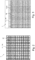
- eine schematische, perspektivische Draufsicht der Ausführungsform des erfindungsgemäßen Filterelementes nach
Figur 1 ; - Figur 3:
- eine schematische Detailansicht der Ausführungsform des erfindungsgemäßen Filterelementes nach
Figur 1 ; - Figur 4:
- eine schematische Schnittansicht der Ausführungsform des erfindungsgemäßen Filterelementes nach
Figur 1 ; und - Figuren 5 bis 9:
- schematische Schnittansichten weiterer Ausführungsformen des erfindungsgemäßen Filterelementes.
- In
Figur 1 ist eine Ausführungsform eines erfindungsgemäßen Filterelementes 1 in perspektivischer Unteransicht gezeigt. Das Filterelement 1 stellt ein rechteckiges Filterelement 1 dar. In der Unteransicht des Filterelementes 1 ist nur die Anströmfläche des Filterelementes 1 zu sehen. Diese Anströmseite wird durch die Grundfläche 110 einer Decklage 11 des Filterelementes 1 gebildet. In der dargestellten Ausführungsform wird die Decklage 11 durch eine Streckmetalllage gebildet. An den Rändern der Grundfläche 110 ist die Decklage 11 nach oben (inFigur 1 nach unten) gebogen. Dadurch werden Seitenflächen 111 der Decklage 11 gebildet, die sich in der gezeigten Ausführungsform senkrecht zu der Grundfläche 110 erstrecken. - Der genauere Aufbau des Filterelementes 1 ist in den
Figuren 2 bis 4 gezeigt. Wie sich ausFigur 4 , die einen Schnitt durch einen seitlichen Teil des Filterelementes 1 nachFigur 1 zeigt, ergibt, weist das Filterelement 1 in der gezeigten Ausführungsform vier Filterlagen 10 auf. Die Filterlagen 10 sind nach unten und zu den Seiten von der Decklage 11 umgeben. Insbesondere liegt die untere Filterlage 10 des Stapels von Filterlagen 10 auf der Decklage 11 auf. Dieser Bereich bildet die Grundfläche 110 der Decklage 11. An den Rändern der Grundfläche 110 ist die Decklage 11 nach oben gebogen und bildet Seitenflächen 112 der Decklage 11. Die Seitenflächen 112 decken die Ränder der Filterlagen 10 zu den Seiten ab. Auf der oberen Filterlage 10 ist eine Verstärkung 12 in Form eines Verstärkungselementes 120 angeordnet. Das Verstärkungselement 120 liegt auf dem Randbereich der oberen Filterlage 10. Das Verstärkungselement 120 ist in der ersten Ausführungsform nach denFiguren 1 bis 4 ein Rahmen mit einem U-förmigen Querschnitt. Die Basis des U-Profils liegt dabei auf dem äußeren Rand der oberen Filterlage 10 und die Schenkel sind nach innen gerichtet. Der untere Schenkel liegt auf der oberen Filterlage 10 auf. Die Seitenfläche 112 der Decklage 11 weist eine Höhe auf, die der Höhe des Stapels der Filterlagen 10 und der Höhe des Verstärkungselementes 120 entspricht. Somit umgibt die Decklage 11 die Filterlagen 10 und das Verstärkungselement 120 zu den Seiten, insbesondere am äußeren Rand. In der gezeigten Ausführungsform weist die Decklage 11 an dem oberen Ende der Seitenfläche 112 eine Abkantung 111 auf. Die Abkantung 111 liegt damit an der Oberseite des Filterelementes 1, das heißt an der der Anströmseite, in der die Grundfläche 110 liegt, abgewandten Seite. Die Abkantung 111 liegt auf der oberen Seite des oberen Schenkels des Verstärkungselementes 120 auf. An dem freien Ende der Abkantung 111 ist diese nach unten und nach außen umgebogen. Hierdurch erstreckt sich die Decklage 11 um das freie Ende des oberen Schenkels des Verstärkungselementes 120 und entlang der Unterseite des oberen Schenkels des Verstärkungselementes 120 nach außen. Somit liegt das Ende der Decklage 11 im Inneren des Verstärkungselementes 120 und eine Verletzung des Benutzers beim Berühren des Filterelementes 1 kann verhindert werden. - In
Figur 5 ist eine zweite Ausführungsform des Filterelementes 1 gezeigt. Diese Ausführungsform unterscheidet sich von der ersten Ausführungsform nur dadurch, dass das Verstärkungselement 120 in Form eines U-förmigen Rahmens auf der Grundfläche 110 der Decklage 11 aufgelegt ist und die Ränder der Filterlagen 10 in dem U-förmigen Profil aufgenommen sind. Zudem ist bei der zweiten Ausführungsform der Umschlag des freien Endes der Abkantung 111 der Decklage 11 nicht gezeigt. Dieser Umschlag kann aber auch bei der zweiten Ausführungsform vorgesehen sein. - In
Figur 6 ist eine dritte Ausführungsform des Filterelementes 1 gezeigt. Diese Ausführungsform unterscheidet sich von der ersten Ausführungsform nur dadurch, dass das Verstärkungselement 120 einen Rahmen mit einem L-förmigen Querschnitt darstellt. Der untere Schenkel des Rahmens liegt auf der oberen Filterlage 10 im Randbereich auf und der zweite Schenkel erstreckt sich vom äußersten Rand der oberen Filterlage 10 nach oben. Das obere Ende des zweiten Schenkels wird von der Decklage 11 durch eine Abkantung 111 und einen an dem freien Ende der Abkantung 111 vorgesehen Abbug umfasst. - In
Figur 7 ist eine vierte Ausführungsform des Filterelementes 1 gezeigt. Diese Ausführungsform unterscheidet sich von der ersten Ausführungsform nur dadurch, dass das Verstärkungselement 120 einen Rahmen mit einem flachen Querschnitt darstellt. Der Rahmen liegt auf der oberen Filterlage 10 im Randbereich auf und wird von der Decklage 11 und insbesondere eine Abkantung 111 nach oben abgedeckt. - In
Figur 8 ist eine fünfte Ausführungsform des Filterelementes 1 gezeigt. Diese Ausführungsform unterscheidet sich von der vierten Ausführungsform nur dadurch, dass das Verstärkungselement 120 in Form des Rahmen mit einem flachen Querschnitt zwischen zwei Filterlagen 10 angeordnet ist. - In
Figur 9 ist eine sechste Ausführungsform des Filterelementes 1 gezeigt. Diese Ausführungsform unterscheidet sich von der fünften Ausführungsform nur dadurch, dass kein Verstärkungselement 120 vorgesehen ist. In der sechsten Ausführungsform wird die Verstärkung 12 durch eine Prägung 121 gebildet. Insbesondere sind die Ränder der Filterlagen 10 miteinander verpresst. Diese geprägten Ränder sind von den Seitenflächen 112 der Deckschicht 11 umgeben und werden nach oben durch die Abkantung 111 der Deckschicht 11 abgedeckt. - Die vorliegende Erfindung unterscheidet sich somit vom Stand der Technik. Im Stand der Technik werden beispielsweise Streckmetallfilter verwendet, die einen im Sichtbereich liegenden Tragrahmen aufweisen. Mit der vorliegenden Erfindung wird hingegen ein Filterelement mit rahmenloser Optik erzeugen. Vorzugsweise weist dieser weiterhin ein Verstärkungselement auf. Dieses kann aus verschiedenen Materialien hergestellt werden. Ebenso kann das Verstärkungselement in verschiedene Geometrien hergestellt werden.
- Zur Herstellung einer Ausführungsform des erfindungsgemäßen Filterelementes kann beispielsweise ein Rahmen mit U-Profil auf die Filterlagen aus Streckmetall gestellt werden. Dadurch wird die Blickdichte auf der Unterseite des Filterelementes, die auch als Vorderseite bezeichnet werden kann, erzeugt. Insbesondere wird der Rahmen durch die Filterlagen verdeckt. Anschließend wird die Decklage über den Rahmen gezogen, so dass dieser nicht sichtbar ist. Alternativ zu den Streckmetall-Filterlagen können verschiedenste andere Materialien, wie zum Beispiel im speziellen PP-Mesh, Schäume, Streckmetalle oder andere Metallgewebe als Filter- und Decklage verwendet werden.
- Die vorliegende Erfindung weist eine Reihe von Vorteilen auf. Insbesondere kann eine homogene Filterfläche ohne Unterbrechung durch den Rahmen erzielt werden. Zudem treten keine Schlieren auf einem sichtbaren Rahmen auf. Bei einer grifflosen Variante können die Kosten verringert werden. Zudem weist bei dieser grifflosen Variante das Filterelement eine bessere Reinigbarkeit auf, da keine Griffverschmutzung auftreten kann.
-
- 1
- Filterelement
- 10
- Filterlage
- 11
- Decklage
- 110
- Grundfläche
- 111
- Abkantung
- 112
- Seitenfläche
- 12
- Verstärkung
- 120
- Verstärkungselement
- 121
- Prägung
Claims (10)
- Filterelement für Dunstabzugsvorrichtung mit mindestens zwei Filterlagen (10), dadurch gekennzeichnet, dass das Filterelement (1) eine Decklage (11), die aus Filtermaterial besteht, aufweist, die die Anströmseite des Filterelementes (1) bildet und die Kanten der Filterlagen (10) abdeckt.
- Filterelement nach Anspruch 1, wobei das Filterelement (1) im Randbereich eine Verstärkung (12) aufweist und die Decklage (11) die Verstärkung (12) abdeckt.
- Filterelement nach Anspruch 2, wobei die Verstärkung (12) eine Prägung (121) von zumindest einem Teil der Filterlagen (10) darstellt.
- Filterelement nach einem der Ansprüche 2 oder 3, wobei die Verstärkung (12) mindestens ein Verstärkungselement (120) umfasst.
- Filterelement nach Anspruch 4, wobei das Verstärkungselement (120) zumindest teilweise auf dem Rand der Filterlage (10) angeordnet ist, die in dem Filterelement (10) der Anströmseite des Filterelementes (1) gegenüberliegt, und zumindest zu den Seiten von der Decklage (11) abgedeckt ist.
- Filterelement nach einem der Ansprüche 4 oder 5, wobei das Verstärkungselement (120) einen Rahmen mit einem U-förmigen, einem L-förmigen, T-förmigen oder einem flachen Querschnitt darstellt.
- Filterelement nach einem der Ansprüche 1 bis 6, wobei die Decklage (11) auf der Seite, die der Anströmseite des Filterelementes (10) gegenüberliegt, eine Abkantung (111), die nach innen gerichtet ist, aufweist.
- Filterelement nach einem der Ansprüche 1 bis 7, wobei die Decklage (11) eine Streckmetalllage darstellt.
- Filterelement nach einem der Ansprüche 4 bis 8, wobei das Filterelement (1) ein magnetisierbares Element aufweist und das magnetisierbare Element das Verstärkungselement (120) bildet.
- Dunstabzugsvorrichtung, dadurch gekennzeichnet, dass die Dunstabzugsvorrichtung zumindest ein Filterelement (1) nach einem der Ansprüche 1 bis 9 aufweist.
Applications Claiming Priority (1)
| Application Number | Priority Date | Filing Date | Title |
|---|---|---|---|
| DE102019210483.5A DE102019210483A1 (de) | 2019-07-16 | 2019-07-16 | Filterelement für Dunstabzugsvorrichtung und Dunstabzugsvorrichtung |
Publications (2)
| Publication Number | Publication Date |
|---|---|
| EP3767185A1 true EP3767185A1 (de) | 2021-01-20 |
| EP3767185B1 EP3767185B1 (de) | 2024-01-24 |
Family
ID=71108502
Family Applications (1)
| Application Number | Title | Priority Date | Filing Date |
|---|---|---|---|
| EP20180830.0A Active EP3767185B1 (de) | 2019-07-16 | 2020-06-18 | Dunstabzugsvorrichtung mit filterelement |
Country Status (2)
| Country | Link |
|---|---|
| EP (1) | EP3767185B1 (de) |
| DE (1) | DE102019210483A1 (de) |
Citations (3)
| Publication number | Priority date | Publication date | Assignee | Title |
|---|---|---|---|---|
| US4689058A (en) * | 1986-02-07 | 1987-08-25 | Kimberly-Clark Corporation | Disposable stove hood filter |
| WO2011047944A1 (de) * | 2009-10-19 | 2011-04-28 | BSH Bosch und Siemens Hausgeräte GmbH | Filterelement für einen ofen |
| DE202011109799U1 (de) * | 2011-09-02 | 2012-04-13 | BSH Bosch und Siemens Hausgeräte GmbH | Filterelement für Dunstabzugshaube |
Family Cites Families (1)
| Publication number | Priority date | Publication date | Assignee | Title |
|---|---|---|---|---|
| US8277530B2 (en) * | 2008-09-24 | 2012-10-02 | Ellis Fibre Usa | Grease removal apparatus, systems and methods |
-
2019
- 2019-07-16 DE DE102019210483.5A patent/DE102019210483A1/de not_active Withdrawn
-
2020
- 2020-06-18 EP EP20180830.0A patent/EP3767185B1/de active Active
Patent Citations (3)
| Publication number | Priority date | Publication date | Assignee | Title |
|---|---|---|---|---|
| US4689058A (en) * | 1986-02-07 | 1987-08-25 | Kimberly-Clark Corporation | Disposable stove hood filter |
| WO2011047944A1 (de) * | 2009-10-19 | 2011-04-28 | BSH Bosch und Siemens Hausgeräte GmbH | Filterelement für einen ofen |
| DE202011109799U1 (de) * | 2011-09-02 | 2012-04-13 | BSH Bosch und Siemens Hausgeräte GmbH | Filterelement für Dunstabzugshaube |
Also Published As
| Publication number | Publication date |
|---|---|
| EP3767185B1 (de) | 2024-01-24 |
| DE102019210483A1 (de) | 2021-01-21 |
Similar Documents
| Publication | Publication Date | Title |
|---|---|---|
| EP1890789B1 (de) | Filteranordnung für dunstabzugshaube | |
| EP2506953A1 (de) | Filterelement für dunstabzugshaube und dunstabzugshaube | |
| EP3789680A1 (de) | Filtereinheit und dunstabzugsvorrichtung mit filtereinheit | |
| EP2772695B1 (de) | Dunstabzugshaube | |
| DE102010039411A1 (de) | Filtereinheit für eine Dunstabzugshaube sowie Dunstabzugshaube | |
| EP3287701A1 (de) | Filtereinheit für eine dunstabzugsvorrichtung und kombinationsgerät mit dunstabzugsvorrichtung und filtereinheit | |
| EP3767185B1 (de) | Dunstabzugsvorrichtung mit filterelement | |
| EP2861910A1 (de) | Filteranordnung für eine dunstabzugshaube | |
| DE102014209955B4 (de) | Rahmenelement für ein Kochfeld | |
| DE102008022536A1 (de) | Gaskochfeld sowie Topfträger für ein solches Gaskochfeld | |
| EP3192578A2 (de) | Filtereinheit für dunstabzugshaube | |
| EP2613096A1 (de) | Haushalts-Dunstabzug mit parallelen Filterplatten | |
| DE10214158A1 (de) | Bodenwanne für eine Sicherheitswerkbank | |
| EP3101349A1 (de) | Dunstabzugshaube | |
| EP2803913B1 (de) | Filterelement für Dunstabzugshaube und Dunstabzugshaube | |
| DE4018881C2 (de) | ||
| DE102013204143A1 (de) | Filtereinheit für Dunstabzugshaube und Dunstabzugshaube | |
| DE69309657T2 (de) | Aus metalldraht hergestellte schublade | |
| EP0459135A1 (de) | Bodenplatte für Doppelböden in belüfteten Räumen, insbesondere Reinräumen | |
| DE102017213678A1 (de) | Dunstabzugsvorrichtung mit Filtereinheit | |
| DE202011109799U1 (de) | Filterelement für Dunstabzugshaube | |
| EP3835663B1 (de) | Kombinationsgerät umfassend ein kochfeld und eine dunstabzugsvorrichtung | |
| DE29811000U1 (de) | Fettfangfilter | |
| EP3926242A1 (de) | Filtereinheit und dunstabzugsvorrichtung | |
| DE9014979U1 (de) | Spritzschutz |
Legal Events
| Date | Code | Title | Description |
|---|---|---|---|
| PUAI | Public reference made under article 153(3) epc to a published international application that has entered the european phase |
Free format text: ORIGINAL CODE: 0009012 |
|
| STAA | Information on the status of an ep patent application or granted ep patent |
Free format text: STATUS: THE APPLICATION HAS BEEN PUBLISHED |
|
| AK | Designated contracting states |
Kind code of ref document: A1 Designated state(s): AL AT BE BG CH CY CZ DE DK EE ES FI FR GB GR HR HU IE IS IT LI LT LU LV MC MK MT NL NO PL PT RO RS SE SI SK SM TR |
|
| AX | Request for extension of the european patent |
Extension state: BA ME |
|
| STAA | Information on the status of an ep patent application or granted ep patent |
Free format text: STATUS: REQUEST FOR EXAMINATION WAS MADE |
|
| 17P | Request for examination filed |
Effective date: 20210720 |
|
| RBV | Designated contracting states (corrected) |
Designated state(s): AL AT BE BG CH CY CZ DE DK EE ES FI FR GB GR HR HU IE IS IT LI LT LU LV MC MK MT NL NO PL PT RO RS SE SI SK SM TR |
|
| STAA | Information on the status of an ep patent application or granted ep patent |
Free format text: STATUS: EXAMINATION IS IN PROGRESS |
|
| 17Q | First examination report despatched |
Effective date: 20230406 |
|
| GRAP | Despatch of communication of intention to grant a patent |
Free format text: ORIGINAL CODE: EPIDOSNIGR1 |
|
| STAA | Information on the status of an ep patent application or granted ep patent |
Free format text: STATUS: GRANT OF PATENT IS INTENDED |
|
| RIC1 | Information provided on ipc code assigned before grant |
Ipc: B01D 46/12 20060101ALI20230830BHEP Ipc: B01D 46/00 20060101ALI20230830BHEP Ipc: F24C 15/20 20060101AFI20230830BHEP |
|
| INTG | Intention to grant announced |
Effective date: 20230913 |
|
| GRAS | Grant fee paid |
Free format text: ORIGINAL CODE: EPIDOSNIGR3 |
|
| GRAA | (expected) grant |
Free format text: ORIGINAL CODE: 0009210 |
|
| STAA | Information on the status of an ep patent application or granted ep patent |
Free format text: STATUS: THE PATENT HAS BEEN GRANTED |
|
| AK | Designated contracting states |
Kind code of ref document: B1 Designated state(s): AL AT BE BG CH CY CZ DE DK EE ES FI FR GB GR HR HU IE IS IT LI LT LU LV MC MK MT NL NO PL PT RO RS SE SI SK SM TR |
|
| REG | Reference to a national code |
Ref country code: GB Ref legal event code: FG4D Free format text: NOT ENGLISH |
|
| REG | Reference to a national code |
Ref country code: CH Ref legal event code: EP |
|
| REG | Reference to a national code |
Ref country code: DE Ref legal event code: R096 Ref document number: 502020006803 Country of ref document: DE |
|
| REG | Reference to a national code |
Ref country code: IE Ref legal event code: FG4D Free format text: LANGUAGE OF EP DOCUMENT: GERMAN |
|
| REG | Reference to a national code |
Ref country code: LT Ref legal event code: MG9D |
|
| REG | Reference to a national code |
Ref country code: NL Ref legal event code: MP Effective date: 20240124 |
|
| PG25 | Lapsed in a contracting state [announced via postgrant information from national office to epo] |
Ref country code: NL Free format text: LAPSE BECAUSE OF FAILURE TO SUBMIT A TRANSLATION OF THE DESCRIPTION OR TO PAY THE FEE WITHIN THE PRESCRIBED TIME-LIMIT Effective date: 20240124 |
|
| PG25 | Lapsed in a contracting state [announced via postgrant information from national office to epo] |
Ref country code: NL Free format text: LAPSE BECAUSE OF FAILURE TO SUBMIT A TRANSLATION OF THE DESCRIPTION OR TO PAY THE FEE WITHIN THE PRESCRIBED TIME-LIMIT Effective date: 20240124 |
|
| PG25 | Lapsed in a contracting state [announced via postgrant information from national office to epo] |
Ref country code: IS Free format text: LAPSE BECAUSE OF FAILURE TO SUBMIT A TRANSLATION OF THE DESCRIPTION OR TO PAY THE FEE WITHIN THE PRESCRIBED TIME-LIMIT Effective date: 20240524 |
|
| PG25 | Lapsed in a contracting state [announced via postgrant information from national office to epo] |
Ref country code: LT Free format text: LAPSE BECAUSE OF FAILURE TO SUBMIT A TRANSLATION OF THE DESCRIPTION OR TO PAY THE FEE WITHIN THE PRESCRIBED TIME-LIMIT Effective date: 20240124 |
|
| PG25 | Lapsed in a contracting state [announced via postgrant information from national office to epo] |
Ref country code: GR Free format text: LAPSE BECAUSE OF FAILURE TO SUBMIT A TRANSLATION OF THE DESCRIPTION OR TO PAY THE FEE WITHIN THE PRESCRIBED TIME-LIMIT Effective date: 20240425 |
|
| PG25 | Lapsed in a contracting state [announced via postgrant information from national office to epo] |
Ref country code: HR Free format text: LAPSE BECAUSE OF FAILURE TO SUBMIT A TRANSLATION OF THE DESCRIPTION OR TO PAY THE FEE WITHIN THE PRESCRIBED TIME-LIMIT Effective date: 20240124 Ref country code: RS Free format text: LAPSE BECAUSE OF FAILURE TO SUBMIT A TRANSLATION OF THE DESCRIPTION OR TO PAY THE FEE WITHIN THE PRESCRIBED TIME-LIMIT Effective date: 20240424 |
|
| PG25 | Lapsed in a contracting state [announced via postgrant information from national office to epo] |
Ref country code: ES Free format text: LAPSE BECAUSE OF FAILURE TO SUBMIT A TRANSLATION OF THE DESCRIPTION OR TO PAY THE FEE WITHIN THE PRESCRIBED TIME-LIMIT Effective date: 20240124 |
|
| PG25 | Lapsed in a contracting state [announced via postgrant information from national office to epo] |
Ref country code: RS Free format text: LAPSE BECAUSE OF FAILURE TO SUBMIT A TRANSLATION OF THE DESCRIPTION OR TO PAY THE FEE WITHIN THE PRESCRIBED TIME-LIMIT Effective date: 20240424 Ref country code: NO Free format text: LAPSE BECAUSE OF FAILURE TO SUBMIT A TRANSLATION OF THE DESCRIPTION OR TO PAY THE FEE WITHIN THE PRESCRIBED TIME-LIMIT Effective date: 20240424 Ref country code: LT Free format text: LAPSE BECAUSE OF FAILURE TO SUBMIT A TRANSLATION OF THE DESCRIPTION OR TO PAY THE FEE WITHIN THE PRESCRIBED TIME-LIMIT Effective date: 20240124 Ref country code: IS Free format text: LAPSE BECAUSE OF FAILURE TO SUBMIT A TRANSLATION OF THE DESCRIPTION OR TO PAY THE FEE WITHIN THE PRESCRIBED TIME-LIMIT Effective date: 20240524 Ref country code: HR Free format text: LAPSE BECAUSE OF FAILURE TO SUBMIT A TRANSLATION OF THE DESCRIPTION OR TO PAY THE FEE WITHIN THE PRESCRIBED TIME-LIMIT Effective date: 20240124 Ref country code: GR Free format text: LAPSE BECAUSE OF FAILURE TO SUBMIT A TRANSLATION OF THE DESCRIPTION OR TO PAY THE FEE WITHIN THE PRESCRIBED TIME-LIMIT Effective date: 20240425 Ref country code: FI Free format text: LAPSE BECAUSE OF FAILURE TO SUBMIT A TRANSLATION OF THE DESCRIPTION OR TO PAY THE FEE WITHIN THE PRESCRIBED TIME-LIMIT Effective date: 20240124 Ref country code: ES Free format text: LAPSE BECAUSE OF FAILURE TO SUBMIT A TRANSLATION OF THE DESCRIPTION OR TO PAY THE FEE WITHIN THE PRESCRIBED TIME-LIMIT Effective date: 20240124 Ref country code: BG Free format text: LAPSE BECAUSE OF FAILURE TO SUBMIT A TRANSLATION OF THE DESCRIPTION OR TO PAY THE FEE WITHIN THE PRESCRIBED TIME-LIMIT Effective date: 20240124 |
|
| PG25 | Lapsed in a contracting state [announced via postgrant information from national office to epo] |
Ref country code: PT Free format text: LAPSE BECAUSE OF FAILURE TO SUBMIT A TRANSLATION OF THE DESCRIPTION OR TO PAY THE FEE WITHIN THE PRESCRIBED TIME-LIMIT Effective date: 20240524 Ref country code: PL Free format text: LAPSE BECAUSE OF FAILURE TO SUBMIT A TRANSLATION OF THE DESCRIPTION OR TO PAY THE FEE WITHIN THE PRESCRIBED TIME-LIMIT Effective date: 20240124 |
|
| PG25 | Lapsed in a contracting state [announced via postgrant information from national office to epo] |
Ref country code: SE Free format text: LAPSE BECAUSE OF FAILURE TO SUBMIT A TRANSLATION OF THE DESCRIPTION OR TO PAY THE FEE WITHIN THE PRESCRIBED TIME-LIMIT Effective date: 20240124 Ref country code: PT Free format text: LAPSE BECAUSE OF FAILURE TO SUBMIT A TRANSLATION OF THE DESCRIPTION OR TO PAY THE FEE WITHIN THE PRESCRIBED TIME-LIMIT Effective date: 20240524 Ref country code: PL Free format text: LAPSE BECAUSE OF FAILURE TO SUBMIT A TRANSLATION OF THE DESCRIPTION OR TO PAY THE FEE WITHIN THE PRESCRIBED TIME-LIMIT Effective date: 20240124 Ref country code: LV Free format text: LAPSE BECAUSE OF FAILURE TO SUBMIT A TRANSLATION OF THE DESCRIPTION OR TO PAY THE FEE WITHIN THE PRESCRIBED TIME-LIMIT Effective date: 20240124 |
|
| PG25 | Lapsed in a contracting state [announced via postgrant information from national office to epo] |
Ref country code: DK Free format text: LAPSE BECAUSE OF FAILURE TO SUBMIT A TRANSLATION OF THE DESCRIPTION OR TO PAY THE FEE WITHIN THE PRESCRIBED TIME-LIMIT Effective date: 20240124 |
|
| PG25 | Lapsed in a contracting state [announced via postgrant information from national office to epo] |
Ref country code: SM Free format text: LAPSE BECAUSE OF FAILURE TO SUBMIT A TRANSLATION OF THE DESCRIPTION OR TO PAY THE FEE WITHIN THE PRESCRIBED TIME-LIMIT Effective date: 20240124 |
|
| PG25 | Lapsed in a contracting state [announced via postgrant information from national office to epo] |
Ref country code: EE Free format text: LAPSE BECAUSE OF FAILURE TO SUBMIT A TRANSLATION OF THE DESCRIPTION OR TO PAY THE FEE WITHIN THE PRESCRIBED TIME-LIMIT Effective date: 20240124 Ref country code: CZ Free format text: LAPSE BECAUSE OF FAILURE TO SUBMIT A TRANSLATION OF THE DESCRIPTION OR TO PAY THE FEE WITHIN THE PRESCRIBED TIME-LIMIT Effective date: 20240124 |
|
| REG | Reference to a national code |
Ref country code: DE Ref legal event code: R097 Ref document number: 502020006803 Country of ref document: DE |
|
| PG25 | Lapsed in a contracting state [announced via postgrant information from national office to epo] |
Ref country code: SK Free format text: LAPSE BECAUSE OF FAILURE TO SUBMIT A TRANSLATION OF THE DESCRIPTION OR TO PAY THE FEE WITHIN THE PRESCRIBED TIME-LIMIT Effective date: 20240124 |
|
| PG25 | Lapsed in a contracting state [announced via postgrant information from national office to epo] |
Ref country code: SM Free format text: LAPSE BECAUSE OF FAILURE TO SUBMIT A TRANSLATION OF THE DESCRIPTION OR TO PAY THE FEE WITHIN THE PRESCRIBED TIME-LIMIT Effective date: 20240124 Ref country code: SK Free format text: LAPSE BECAUSE OF FAILURE TO SUBMIT A TRANSLATION OF THE DESCRIPTION OR TO PAY THE FEE WITHIN THE PRESCRIBED TIME-LIMIT Effective date: 20240124 Ref country code: EE Free format text: LAPSE BECAUSE OF FAILURE TO SUBMIT A TRANSLATION OF THE DESCRIPTION OR TO PAY THE FEE WITHIN THE PRESCRIBED TIME-LIMIT Effective date: 20240124 Ref country code: DK Free format text: LAPSE BECAUSE OF FAILURE TO SUBMIT A TRANSLATION OF THE DESCRIPTION OR TO PAY THE FEE WITHIN THE PRESCRIBED TIME-LIMIT Effective date: 20240124 Ref country code: CZ Free format text: LAPSE BECAUSE OF FAILURE TO SUBMIT A TRANSLATION OF THE DESCRIPTION OR TO PAY THE FEE WITHIN THE PRESCRIBED TIME-LIMIT Effective date: 20240124 |
|
| PLBE | No opposition filed within time limit |
Free format text: ORIGINAL CODE: 0009261 |
|
| STAA | Information on the status of an ep patent application or granted ep patent |
Free format text: STATUS: NO OPPOSITION FILED WITHIN TIME LIMIT |
|
| 26N | No opposition filed |
Effective date: 20241025 |
|
| PG25 | Lapsed in a contracting state [announced via postgrant information from national office to epo] |
Ref country code: MC Free format text: LAPSE BECAUSE OF FAILURE TO SUBMIT A TRANSLATION OF THE DESCRIPTION OR TO PAY THE FEE WITHIN THE PRESCRIBED TIME-LIMIT Effective date: 20240124 |
|
| REG | Reference to a national code |
Ref country code: CH Ref legal event code: PL |
|
| PG25 | Lapsed in a contracting state [announced via postgrant information from national office to epo] |
Ref country code: LU Free format text: LAPSE BECAUSE OF NON-PAYMENT OF DUE FEES Effective date: 20240618 |
|
| GBPC | Gb: european patent ceased through non-payment of renewal fee |
Effective date: 20240618 |
|
| PG25 | Lapsed in a contracting state [announced via postgrant information from national office to epo] |
Ref country code: IE Free format text: LAPSE BECAUSE OF NON-PAYMENT OF DUE FEES Effective date: 20240618 |
|
| PG25 | Lapsed in a contracting state [announced via postgrant information from national office to epo] |
Ref country code: CH Free format text: LAPSE BECAUSE OF NON-PAYMENT OF DUE FEES Effective date: 20240630 Ref country code: SI Free format text: LAPSE BECAUSE OF FAILURE TO SUBMIT A TRANSLATION OF THE DESCRIPTION OR TO PAY THE FEE WITHIN THE PRESCRIBED TIME-LIMIT Effective date: 20240124 Ref country code: BE Free format text: LAPSE BECAUSE OF NON-PAYMENT OF DUE FEES Effective date: 20240630 |
|
| PG25 | Lapsed in a contracting state [announced via postgrant information from national office to epo] |
Ref country code: FR Free format text: LAPSE BECAUSE OF NON-PAYMENT OF DUE FEES Effective date: 20240630 |
|
| PG25 | Lapsed in a contracting state [announced via postgrant information from national office to epo] |
Ref country code: GB Free format text: LAPSE BECAUSE OF NON-PAYMENT OF DUE FEES Effective date: 20240618 |
|
| REG | Reference to a national code |
Ref country code: BE Ref legal event code: MM Effective date: 20240630 |
|
| PGFP | Annual fee paid to national office [announced via postgrant information from national office to epo] |
Ref country code: DE Payment date: 20250630 Year of fee payment: 6 |
|
| PGFP | Annual fee paid to national office [announced via postgrant information from national office to epo] |
Ref country code: AT Payment date: 20250721 Year of fee payment: 5 |
|
| PGFP | Annual fee paid to national office [announced via postgrant information from national office to epo] |
Ref country code: IT Payment date: 20250630 Year of fee payment: 6 |
|
| PG25 | Lapsed in a contracting state [announced via postgrant information from national office to epo] |
Ref country code: RO Free format text: LAPSE BECAUSE OF FAILURE TO SUBMIT A TRANSLATION OF THE DESCRIPTION OR TO PAY THE FEE WITHIN THE PRESCRIBED TIME-LIMIT Effective date: 20240124 |
|
| PG25 | Lapsed in a contracting state [announced via postgrant information from national office to epo] |
Ref country code: CY Free format text: LAPSE BECAUSE OF FAILURE TO SUBMIT A TRANSLATION OF THE DESCRIPTION OR TO PAY THE FEE WITHIN THE PRESCRIBED TIME-LIMIT; INVALID AB INITIO Effective date: 20200618 |
|
| PG25 | Lapsed in a contracting state [announced via postgrant information from national office to epo] |
Ref country code: HU Free format text: LAPSE BECAUSE OF FAILURE TO SUBMIT A TRANSLATION OF THE DESCRIPTION OR TO PAY THE FEE WITHIN THE PRESCRIBED TIME-LIMIT; INVALID AB INITIO Effective date: 20200618 |