EP3766770A1 - Zugdurchführung für ein fahrrad - Google Patents
Zugdurchführung für ein fahrrad Download PDFInfo
- Publication number
- EP3766770A1 EP3766770A1 EP20153428.6A EP20153428A EP3766770A1 EP 3766770 A1 EP3766770 A1 EP 3766770A1 EP 20153428 A EP20153428 A EP 20153428A EP 3766770 A1 EP3766770 A1 EP 3766770A1
- Authority
- EP
- European Patent Office
- Prior art keywords
- cable
- train
- opening
- cable bushing
- bushing according
- Prior art date
- Legal status (The legal status is an assumption and is not a legal conclusion. Google has not performed a legal analysis and makes no representation as to the accuracy of the status listed.)
- Granted
Links
Images


Classifications
-
- B—PERFORMING OPERATIONS; TRANSPORTING
- B62—LAND VEHICLES FOR TRAVELLING OTHERWISE THAN ON RAILS
- B62J—CYCLE SADDLES OR SEATS; AUXILIARY DEVICES OR ACCESSORIES SPECIALLY ADAPTED TO CYCLES AND NOT OTHERWISE PROVIDED FOR, e.g. ARTICLE CARRIERS OR CYCLE PROTECTORS
- B62J11/00—Supporting arrangements specially adapted for fastening specific devices to cycles, e.g. supports for attaching maps
- B62J11/10—Supporting arrangements specially adapted for fastening specific devices to cycles, e.g. supports for attaching maps for mechanical cables, hoses, pipes or electric wires, e.g. cable guides
-
- B—PERFORMING OPERATIONS; TRANSPORTING
- B62—LAND VEHICLES FOR TRAVELLING OTHERWISE THAN ON RAILS
- B62J—CYCLE SADDLES OR SEATS; AUXILIARY DEVICES OR ACCESSORIES SPECIALLY ADAPTED TO CYCLES AND NOT OTHERWISE PROVIDED FOR, e.g. ARTICLE CARRIERS OR CYCLE PROTECTORS
- B62J11/00—Supporting arrangements specially adapted for fastening specific devices to cycles, e.g. supports for attaching maps
- B62J11/10—Supporting arrangements specially adapted for fastening specific devices to cycles, e.g. supports for attaching maps for mechanical cables, hoses, pipes or electric wires, e.g. cable guides
- B62J11/13—Supporting arrangements specially adapted for fastening specific devices to cycles, e.g. supports for attaching maps for mechanical cables, hoses, pipes or electric wires, e.g. cable guides specially adapted for mechanical cables
-
- F—MECHANICAL ENGINEERING; LIGHTING; HEATING; WEAPONS; BLASTING
- F16—ENGINEERING ELEMENTS AND UNITS; GENERAL MEASURES FOR PRODUCING AND MAINTAINING EFFECTIVE FUNCTIONING OF MACHINES OR INSTALLATIONS; THERMAL INSULATION IN GENERAL
- F16C—SHAFTS; FLEXIBLE SHAFTS; ELEMENTS OR CRANKSHAFT MECHANISMS; ROTARY BODIES OTHER THAN GEARING ELEMENTS; BEARINGS
- F16C1/00—Flexible shafts; Mechanical means for transmitting movement in a flexible sheathing
- F16C1/10—Means for transmitting linear movement in a flexible sheathing, e.g. "Bowden-mechanisms"
-
- F—MECHANICAL ENGINEERING; LIGHTING; HEATING; WEAPONS; BLASTING
- F16—ENGINEERING ELEMENTS AND UNITS; GENERAL MEASURES FOR PRODUCING AND MAINTAINING EFFECTIVE FUNCTIONING OF MACHINES OR INSTALLATIONS; THERMAL INSULATION IN GENERAL
- F16C—SHAFTS; FLEXIBLE SHAFTS; ELEMENTS OR CRANKSHAFT MECHANISMS; ROTARY BODIES OTHER THAN GEARING ELEMENTS; BEARINGS
- F16C2326/00—Articles relating to transporting
- F16C2326/20—Land vehicles
- F16C2326/26—Bicycle steering or suspension
Definitions
- the invention relates to a cable bushing for a bicycle, that is to say an insertable bushing through which trains or cables can be introduced into the frame or fork of a bicycle.
- So-called cable bushings are known for the internal routing of cables for gearshifts and brakes or cables.
- Such cable ducts are used for bicycles, which also include e-bikes, pedelecs and cargo bikes (also with three or four wheels).
- the invention is based on the object of making the assembly of a train bushing even simpler.
- the threading of the cable feedthrough in the opening is to be made easier and / or the seating of the cable feedthrough in the opening is to be improved.
- the invention relates to a cable duct for a bicycle.
- the invention relates to a cable bushing which is inserted into the opening of the tube of a frame or a fork of the bicycle.
- the cable bushing comprises an upper part and a lower part, the upper part and the lower part being able to be fixed by pulling them together in an opening of a frame or a fork.
- the fixing is preferably carried out in a form-fitting manner, with one edge of the upper part or lower part resting on each side of the opening.
- At least one channel extends through the upper part and the lower part.
- the train duct can also be used to lay trains in the narrower sense, as well as electrical or hydraulic lines.
- the upper part and / or the lower part comprises a lateral slot for threading a train or a cable into the at least one channel.
- the at least one channel is therefore accessible from the side via the slot.
- the slot can be bent open and the train or cable inserted into the duct.
- the width of the slot in one embodiment of the invention is less than 3 mm, preferably less than 1 and particularly preferably less than 0.5 mm.
- only the upper part comprises a lateral slot.
- the channel of the lower part is laterally opened to such an extent that at least in the unassembled state the pull or the cable can be inserted from the side without widening the channel.
- the side wall of the upper part and / or lower part comprises, adjacent to the slot, a bevel which merges into the slot.
- the edge of the slot adjacent to the side wall is therefore beveled in such a way that when a pull or a pull is pushed in Cable the slot is widened.
- the bevel preferably has a width of at least 0.5 mm.
- the bevel and the slot preferably run parallel to the at least one channel.
- the chamfer, slot and channel are transverse but not perpendicular to the top of the upper part.
- the cable feedthrough comprises at least two channels which merge into one another.
- the channels overlap in such a way that at the same time a guide for the respective train or the respective cable in the form of separate channel-shaped guides is retained.
- the channels are each spaced apart from one another by more than half of their respective diameter (based on the lateral distance to the edge which is formed by the intersection).
- the cable feedthrough is designed such that the at least one channel has an offset between the upper part and the lower part in the assembled state.
- the offset causes a narrowing of the free cross-section of the channel and thus clamps the train or the cable during assembly.
- such a narrowing can be formed in particular by the fact that the upper part and the lower part are moved towards one another during assembly.
- the upper part and the lower part can still be spaced from one another to such an extent that the train or the cable can be pulled through the duct without exerting force. Only with the assembly and the associated train of moving the upper part and the lower part towards each other is the train or the cable clamped.
- the offset is preferably dimensioned in such a way that the train or the cable is clamped, but can still be pulled through the cable bushing with the application of force. Subsequent pulling out or pushing in of a section of the pull or cable is also possible.
- the pull or the cable can be pulled out with a force of more than 5 N and / or less than 50 N.
- the maximum offset is preferably less than 3 mm and more than 0.5 mm.
- the lower part comprises a contact surface on two opposite sides for the underside of the frame or the fork adjoining the opening of the lower part.
- the contact surfaces of the lower part are located in particular on the narrow sides of the lower part.
- the other opposite sides of the lower part preferably do not include any contact surface for the underside of the frame or the fork.
- the lower part can be threaded in in a simple manner in that it is first pushed so far to one side behind the opening that the opposite side of the lower part fits through. The lower part can then be pulled forward again in such a way that the contact surfaces adjoin the opening on the underside of the frame or the fork.
- a remaining central part protruding beyond the contact surfaces is preferably seated in the opening and thus centers the lower part in the opening in a form-fitting manner.
- the upper part preferably comprises a circumferential contact surface for the upper side of the frame or fork adjoining the opening.
- the upper part does not have to be threaded through the opening, it preferably comprises a collar which forms a circumferential contact surface for the upper side.
- the upper part is preferably designed in such a way that it has such a large width everywhere that it cannot be threaded into the opening of the frame or the fork.
- the upper part is preferably centered independently over a remaining central part which projects beyond the collar that forms the contact surface.
- the above-defined remaining middle part of the upper or lower part can be polygonal, in particular square.
- the remaining one tapers Middle part in one threading direction.
- the corresponding opening in the frame or in the fork is also polygonal, in particular square.
- the remaining central part and opening are trapezoidal.
- the overall width of the cable feedthrough preferably tapers. This particularly facilitates the threading of the lower part.
- the cable feedthrough is designed as a square in plan view.
- the cable feedthrough can be essentially trapezoidal.
- the at least one channel preferably runs obliquely, but not perpendicularly, to the top of the cable feedthrough.
- the at least one channel runs at an angle of 30 ° to 70 ° to the top of the cable duct. This particularly facilitates the alignment of the cables or cables in the direction of the handlebar, where cables or cables are usually attached.
- the upper part and the lower part can preferably be drawn together by means of at least one screw.
- a cable feedthrough are provided, which can be used flexibly for different wall thicknesses.
- the screws are preferably arranged diagonally opposite one another, the at least one channel being positioned between the screws.
- the at least one screw is preferably designed as a thread-forming screw.
- the upper part and the lower part are preferably pre-assembled and, in the pre-assembled state, can be inserted into the opening of the frame or the fork.
- a pre-assembly of this type is particularly easy to implement via a thread-forming screw, since it jams when it is screwed in, in particular in a through hole provided for this purpose.
- the two screws are already screwed into the lower part and thus hold the upper part and lower part together.
- the upper part and the lower part can, however, still be spaced apart from one another in such a way that the lower part can be threaded into the opening of the frame or the fork.
- the lower part is then threaded into the opening in the frame or fork.
- the upper part is now already centered in the opening with a positive fit due to a protruding middle part.
- the screws can now be tightened in order to fix the cable feedthrough positively in the opening.
- the train or cable will be pinched due to the offset of the duct.
- FIGS. 7 and 8 an alternative embodiment of a train feedthrough is to be explained.
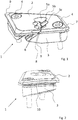
- Fig. 1 shows a perspective view of an exemplary embodiment of a cable feedthrough 1 according to the invention.
- the cable bushing 1 comprises an upper part 2 and a lower part 3.
- the cable feedthrough 1 comprises the channels 5a-5c, which extend obliquely but not perpendicularly through the upper part 2 and lower part 3.
- the channels 5a-5c overlap so that trains or cables can be pressed over the outermost channel 5c to the inside into the channel 5a.
- channels 5a-5c can each have a different diameter adapted to the respective train or cable.
- the side wall 7 merges into the top of the upper part 2 via a bevel 9.
- the heads of the screws 4 are preferably completely countersunk in the upper part 3.
- the upper part 2 comprises a lateral slot 6.
- the slot 6 runs parallel to the channels 5a-5c, that is, transversely, but not perpendicularly to the top.
- the edges formed by the slot 6 are each provided with a bevel 8.
- the bevels 8 widen the upper part 2 when a pull or a cable is pushed in along the slot 6, so that the pull or the cable can be threaded into the channels 5a-5c from the side.
- Fig. 2 is a view of the narrow side of the cable feedthrough 1. In this view it can be seen in particular that the upper part 2 and lower part 3 can be adapted to the curvature of the frame.
- a slot 10 is located between the upper part 2 and the lower part 3, within which the wall of the frame (not shown) adjoining the opening is enclosed in the assembled state.
- Fig. 3 is a sectional view of the pull-through 1 along its main direction of extent.
- the slot 10 which is formed by a collar 11 of the upper part 2 and the lower part 3 protruding under the collar, can be seen particularly well in this view.
- the slot is through the contact surface 12 of the upper part 2 and the Contact surface 15a or 15b of the lower part (see Fig. 5 ) educated.
- the channel 5b has an offset in the assembled state.
- the section of the channel 5 b leading through the upper part 2 therefore merges via a step into the section located in the lower part 3.
- the channel 5b runs obliquely but not vertically, preferably at an angle of 30 to 70 ° to the top, the offset only occurs when the upper part 2 and lower part 3 are moved towards one another by tightening the screws 4.
- the free cross section of the channel 5b narrows in the area of the offset and the train or cable is pinched.
- the lower part 3 On the underside, the lower part 3 is provided with a bevel 13 in the region of the channels 5a to 5c. As a result, the lower part 3 is laterally narrower and the train or the cable can be guided better inside along the tube of the frame.
- FIG. 3 is a view of the underside of the pull-through 1.
- the circumferential contact surface 12 of the upper part 2 can be seen, which protrudes beyond the lower part 3 on the long sides.
- the lower part itself engages with its own contact surface (15a, 15b, see FIG Fig. 5 ) under the wall of the frame adjacent to the opening so that the The contact surface 12 is covered by the lower part 3 on the narrow sides.
- the lower part 3 can comprise a central recess 14, which primarily serves to save weight.
- Fig. 5 is a perspective view of the lower part 3.
- the lower part 3 comprises the channels 5a-5c lying next to one another and merging into one another.
- a train or cable can be fed into the following channels 5a and 5b via channel 5c.
- the lower part comprises the two opposing contact surfaces 15a and 15b, which in this exemplary embodiment are arranged on the narrow side.
- the lower part tapers in the direction of the contact surface 15b.
- the lower part 3 does not include any contact surface on the long sides.
- the lower part 3 can thus be threaded into the opening, preferably with the contact surface 15b on the narrower side first, is then pushed back again so that both contact surfaces 15a, 15b grip under the wall of the frame adjacent to the opening.
- the lower part 3 Due to the protruding middle part 17 remaining between the contact surfaces, the lower part 3 is centered.
- the lower part 3 Adjacent to the contact surfaces 15a, 15b, the lower part 3 can be understood to have a bevel 16, which facilitates threading.
- Fig. 6 shows the upper part 2 from the bottom.
- the upper part 2 comprises a circumferential contact surface 12 which is formed by a collar 11 protruding laterally.
- the upper part 3 is centered over the remaining middle part 18.
- the side slot 6 for threading trains and cables can also be seen.
- the cable bushing 1 shown here is preferably used in the pre-assembled state.
- the traction bushing 1 is essentially trapezoidal.
- the upper part 2 and the lower part 3 can still be spaced from one another.
- Trains and cables can initially be introduced in a simple manner by widening the upper part 2 through the slot 6.
- the lower part 2 can then be threaded into the frame.
- the upper part 2 is centered over the remaining central part 18.
- the remaining middle part 17 of the lower part is moved into the opening and the cable feedthrough is then secured in the opening with a positive fit. A frictional connection by jamming is not necessary.
- the cable feedthrough 1 can be used flexibly for different wall thicknesses, provided that the screws are correspondingly long, e.g. for aluminum or carbon frames.
- FIGS. 7 and 8 are perspective views of a further embodiment of a train bushing 1 according to the invention.
- the cable duct shown in FIGS. 7 and 8 shown duct 1 two instead of three channels 5a, 5b.
- the cable feedthrough 1 is designed in accordance with the cable feedthrough described above and includes in particular a lateral slot 6 in the upper part 2, via which a cable or a cable can be threaded into the channels 5a, 5b.
- the invention made it possible to provide a cable duct which is easier to assemble.
Landscapes
- Engineering & Computer Science (AREA)
- Mechanical Engineering (AREA)
- Installation Of Indoor Wiring (AREA)
Abstract
Description
- Die Erfindung betrifft eine Zugdurchführung für ein Fahrrad, also eine einsetzbare Durchführung, über die Züge oder Kabel in den Rahmen oder die Gabel eines Fahrrads einführbar sind.
- Für die innenliegende Verlegung von Zügen für Schaltung und Bremse oder Kabel sind sogenannte Zugdurchführungen bekannt. Derartige Zugdurchführungen werden für Fahrräder verwendet, zu denen z.B. auch E-Bikes, Pedelecs und Lastenräder (auch mit drei oder vier Rädern) zählen.
- So zeigt die Offenlegungsschrift
EP 3 034 386 A1 eine zweiteilig ausgebildete Zugdurchführung, welche sich formschlüssig in die Öffnung eines Rahmens einsetzen lässt. - Dadurch, dass sich die Zugdurchführung einfädeln lässt, ist eine einfache Montage gewährleistet.
- Nachteilig ist allerdings, dass der Zug bzw. das Kabel durch die Öffnung, die durch die Zugdurchführung gebildet wird, durchgezogen werden muss.
- Der Erfindung liegt demgegenüber die Aufgabe zugrunde, die Montage einer Zugdurchführung noch einfacher auszugestalten.
- Weiter soll das Einfädeln der Zugdurchführung in der Öffnung erleichtert und/oder der Sitz der Zugdurchführung in der Öffnung verbessert werden.
- Die Aufgabe der Erfindung wird bereits durch eine Zugdurchführung für ein Fahrrad nach Anspruch 1 gelöst.
- Bevorzugte Ausführungsformen und Weiterbildungen der Erfindung sind dem Gegenstand der abhängigen Ansprüche, der Beschreibung sowie den Zeichnungen zu entnehmen.
- Die Erfindung betrifft eine Zugdurchführung für ein Fahrrad. Insbesondere betrifft die Erfindung eine Zugdurchführung, welche in die Öffnung des Rohres eines Rahmens oder einer Gabel des Fahrrad eingesetzt wird.
- Die Zugdurchführung umfasst ein Oberteil und ein Unterteil, wobei Oberteil und Unterteil durch Zusammenziehen in einer Öffnung eines Rahmens bzw. einer Gabel festlegbar sind.
- Vorzugsweise erfolgt das Festlegen formschlüssig, wobei eine Kante des Oberteils oder Unterteils an jeder Seite der Öffnung anliegt.
- Als Durchführung für einen Zug oder ein Kabel erstreckt sich zumindest ein Kanal durch Oberteil und Unterteil.
- Die Zugdurchführung kann auch sowohl dem Verlegen von Zügen im engeren Sinne, als auch von elektrischen oder hydraulischen Leitungen dienen.
- Gemäß der Erfindung umfasst das Oberteil und/oder das Unterteil einen seitlichen Schlitz zum Einfädeln eines Zugs oder eines Kabels in den zumindest einen Kanal.
- Der zumindest eine Kanal ist also seitlich über den Schlitz zugänglich.
- Zur Montage kann der Schlitz aufgebogen und der Zug oder das Kabel in den Kanal eingeführt werden.
- Es versteht sich, dass in nicht aufgeweitetem Zustand der Schlitz schmäler ist als der Zug oder das Kabel, welches durch den Schlitz geführt werden soll. So wird der Zug oder das Kabel nach dem Aufweiten und Einsetzen in Position gehalten.
- Insbesondere beträgt die Breite des Schlitzes bei einer Ausführungsform der Erfindung weniger als 3 mm, bevorzugt weniger als 1 und besonders bevorzugt weniger als 0,5 mm.
- Gemäß einer bevorzugten Ausführungsform der Erfindung umfasst nur das Oberteil einen seitlichen Schlitz. So braucht zum Einfädeln des Zugs oder des Kabels in den Kanal nur das Oberteil auseinandergespreizt bzw. aufgeweitet zu werden.
- Der Kanal des Unterteils ist dagegen seitlich derart weit geöffnet, dass zumindest im nichtmontierten Zustand der Zug oder das Kabel seitlich eingeführt werden kann, ohne den Kanal aufzuweiten.
- Gemäß einer bevorzugten Ausführungsform der Erfindung umfasst die Seitenwand des Oberteils und/oder Unterteils angrenzend an den Schlitz eine Fase, welche in den Schlitz übergeht.
- Die Kante des Schlitzes angrenzend zur Seitenwand ist also derart gefast, dass beim Eindrücken eines Zugs oder eines Kabels der Schlitz aufgeweitet wird. Die Fase hat vorzugsweise eine Breite von mindestens 0,5 mm.
- So wird das Einfädeln des Zugs oder des Kabels in den Kanal weiter erleichtert.
- Die Fase und der Schlitz verlaufen vorzugsweise parallel zu dem zumindest einen Kanal. Insbesondere stehen Fase, Schlitz und Kanal quer aber nicht senkrecht zur Oberseite des Oberteils.
- Gemäß einer Weiterbildung der Erfindung umfasst die Zugdurchführung zumindest zwei Kanäle, welche ineinander übergehen.
- In vielen Anwendungsfällen sind mehrere Züge bzw. Kabel durchzuführen. Über Kanäle, die sich überschneiden, also ineinander übergehen, können von einer Seite mehrere Züge bzw. Kabel eingefädelt werden.
- Die Kanäle überschneiden sich dabei derart, dass gleichzeitig weiterhin eine Führung für den jeweiligen Zug bzw. das jeweilige Kabel in Form von getrennten kanalförmigen Führungen erhalten bleibt. Insbesondere sind die Kanäle jeweils um mehr als die Hälfte ihres jeweiligen Durchmessers voneinander beabstandet (bezogen auf den seitlichen Abstand zur Kante, die durch die Überschneidung gebildet wird).
- Gemäß einer Weiterbildung der Erfindung ist die Zugdurchführung derart ausgebildet, dass der zumindest eine Kanal im montierten Zustand einen Versatz zwischen Oberteil und Unterteil aufweist.
- Der Versatz bedingt eine Verengung des freien Querschnitts des Kanals und klemmt somit beim Montieren den Zug oder das Kabel fest.
- Bei einem schräg zur Oberseite der Zugdurchführung verlaufenden Kanal kann eine derartige Verengung insbesondere dadurch gebildet werden, dass Oberteil und Unterteil beim Montieren aufeinander zubewegt werden. So können im nichtmontierten Zustand Oberteil und Unterteil noch derart weit voneinander beabstandet sein, dass der Zug bzw. das Kabel ohne Kraftanstrengung durch den Kanal gezogen werden kann. Erst mit dem Montieren und dem damit verbundenen Zug Aufeinanderzubewegen von Oberteil und Unterteil wird der Zug oder das Kabel festgeklemmt.
- Vorzugsweise ist der Versatz aber derart dimensioniert, dass der Zug bzw. das Kabel zwar festgeklemmt wird, sich aber weiterhin noch mit Kraftaufwand durch die Zugdurchführung durchziehen lässt. So ist auch noch ein nachträgliches Herausziehen oder Hineindrücken eines Abschnitts des Zugs oder des Kabels möglich. Insbesondere lässt sich der Zug oder das Kabel mit einer Kraft von mehr als 5 N und/oder weniger als 50 N herausziehen.
- Im montierten Zustand beträgt der maximale Versatz vorzugsweise weniger als 3 mm und mehr als 0,5 mm.
- Gemäß einer bevorzugten Ausführungsform der Erfindung umfasst das Unterteil auf zwei sich gegenüberliegenden Seiten jeweils eine Anlagefläche für die an die Öffnung des Unterteils angrenzende Unterseite des Rahmens bzw. der Gabel.
- Die Anlageflächen des Unterteils befinden sich insbesondere an den Schmalseiten des Unterteils.
- Die anderen gegenüberliegenden Seiten des Unterteils umfassen dagegen vorzugsweise keine Anlagefläche für die Unterseite des Rahmens bzw. der Gabel.
- So kann zum Montieren das Unterteil auf einfache Weise eingefädelt werden, indem dieses zunächst derart weit auf eine Seite hinter die Öffnung geschoben wird, dass die gegenüberliegende Seite des Unterteils durch passt. Sodann kann das Unterteil wieder vorgezogen werden derart, dass die Anlageflächen angrenzend an die Öffnung an der Unterseite des Rahmens bzw. der Gabel anliegen.
- Ein die Anlageflächen überragendes verbleibendes Mittelteil sitzt dabei vorzugsweise in der Öffnung und zentriert so formschlüssig das Unterteil in der Öffnung.
- Das Oberteil umfasst vorzugsweise eine umlaufende Anlagefläche für die an die Öffnung angrenzende Oberseite des Rahmens bzw. der Gabel.
- Da das Oberteil nicht durch die Öffnung eingefädelt werden muss, umfasst dieses vorzugsweise einen Kragen, welcher eine umlaufende Anlagefläche für die Oberseite bildet.
- Das Oberteil ist vorzugsweise derart ausgebildet, dass überall eine derart große Breite hat, dass es nicht in die Öffnung des Rahmens bzw. der Gabel eingefädelt werden kann.
- Das Oberteil zentriert sich vorzugsweise selbstständig über ein verbleibendes Mittelteil, welches den Kragen, der die Anlagefläche bildet, überragt.
- Das vorstehend definierte verbleibende Mittelteil des Ober- oder Unterteils kann polygonal, insbesondere viereckig ausgebildet sein. Vorzugsweise verjüngt sich das verbleibende Mittelteil in einer Einfädelrichtung. Dem entsprechende ist auch die korrespondierende Öffnung im Rahmen bzw. in der Gabel polygonal, insbesondere viereckig, ausgebildet.
- Insbesondere sind verbleibendes Mittelteil und Öffnung trapezförmig ausgebildet.
- Die Zugdurchführung verjüngt sich vorzugsweise insgesamt in ihrer Breite. Dies erleichtert insbesondere das Einfädeln des Unterteils.
- Gemäß einer bevorzugten Ausführungsform der Erfindung ist die Zugdurchführung in der Draufsicht als Viereck ausgebildet.
- Insbesondere kann die Zugdurchführung im Wesentlichen trapezförmig ausgebildet sein.
- Der zumindest eine Kanal verläuft vorzugsweise schräg, aber nicht senkrecht zur Oberseite der Zugdurchführung.
- Insbesondere verläuft der zumindest eine Kanal in einem Winkel von 30° bis 70° zur Oberseite der Zugdurchführung. Dies erleichtert insbesondere das Ausrichten der Züge bzw. Kabel in Richtung des Lenkers, wo Züge bzw. Kabel in der Regel angebracht werden.
- Oberteil und Unterteil sind vorzugsweise mittels zumindest einer Schraube zusammenziehbar.
- Insbesondere ist vorgesehen, dass Oberteil und Unterteil mittels zwei Schrauben zusammengezogen werden.
- So kann, insbesondere wenn Unterteil und/oder Oberteil formschlüssig in die Öffnung greifen, eine Zugdurchführung bereit gestellt werden, welche flexibel für unterschiedliche Wandstärken verwendbar ist.
- Die Schrauben sind vorzugsweise diagonal gegenüber angeordnet, wobei zwischen den Schrauben der zumindest eine Kanal positioniert ist.
- Die zumindest eine Schraube ist vorzugsweise als gewindeformende Schraube ausgebildet.
- Vorzugsweise sind Oberteil und Unterteil vormontiert und im vormontierten Zustand in die Öffnung des Rahmens bzw. der Gabel einsetzbar.
- Über eine gewindeformende Schraube ist eine derartige Vormontage besonders einfach zu realisieren, da sich diese beim Eindrehen, insbesondere in ein dafür vorgesehenes Durchgangsloch, verklemmt.
- Es ist insbesondere vorgesehen, dass die beiden Schrauben bereits in das Unterteil eingedreht sind und so Oberteil und Unterteil zusammenhalten.
- Oberteil und Unterteil können in diesem vormontierten Zustand aber noch derart voneinander beabstandet sein, dass das Unterteil in die Öffnung des Rahmens bzw. der Gabel eingefädelt werden kann.
- Zur Montage wird zunächst der Zug bzw. das Kabel seitlich durch den Schlitz in die Zugdurchführung eingefädelt.
- Sodann wird das Unterteil in die Öffnung des Rahmens bzw. der Gabel eingefädelt. Das Oberteil ist aufgrund eines hervorstehenden Mittelteils nunmehr bereits formschlüssig in der Öffnung zentriert.
- Die Schrauben können nunmehr angezogen werden, um die Zugdurchführung formschlüssig in der Öffnung festzusetzen. Dabei wird der Zug oder das Kabel aufgrund des Versatzes des Kanals eingeklemmt.
- Nach dem Befestigen können aber immer noch Anpassungen der herausgeführten Länge durch Herein- oder Herausschieben des Zugs oder des Kabels vorgenommen werden.
- Der Gegenstand der Erfindung soll im Folgenden bezugnehmend auf die Zeichnungen
Fig. 1 bis Fig. 8 anhand eines Ausführungsbeispiels der Erfindung näher erläutert werden. -
Fig. 1 ist eine perspektivische Ansicht einer erfindungsgemäßen Zugdurchführung. -
Fig. 2 ist eine Seitenansicht der Zugdurchführung auf die Schmalseite. -
Fig. 3 ist eine Schnittansicht der Zugdurchführung im montierten Zustand entlang ihrer Haupterstreckungsrichtung. -
Fig. 4 zeigt die Zugdurchführung von der Unterseite. -
Fig. 5 ist eine perspektivische Ansicht des Unterteils der Zugdurchführung. -
Fig. 6 ist eine perspektivische Ansicht des Oberteils der Zugdurchführung. - Bezugnehmend auf die perspektivischen Ansichten gemäß
Fig. 7 und Fig. 8 soll ein alternatives Ausführungsbeispiel einer Zugdurchführung erläutert werden. -
Fig. 1 zeigt in einer perspektivischen Ansicht ein Ausführungsbeispiel einer erfindungsgemäßen Zugdurchführung 1. - Die Zugdurchführung 1 umfasst ein Oberteil 2 sowie ein Unterteil 3.
- Oberteil 2 und Unterteil 3 sind mittels den diagonal gegenüberliegenden Schrauben 4 miteinander verbunden.
- Die Zugdurchführung 1 umfasst in diesem Ausführungsbeispiel die Kanäle 5a-5c, welche sich schräg, aber nicht senkrecht durch Oberteil 2 und Unterteil 3 erstrecken.
- Die Kanäle 5a-5c überschneiden sich, so dass Züge oder Kabel über den äußersten Kanal 5c bis nach innen in den Kanal 5a gedrückt werden können.
- Es versteht sich, dass die Kanäle 5a-5c jeweils einen unterschiedlichen an den jeweiligen Zug oder das Kabel angepassten Durchmesser aufweisen können.
- Die Seitenwand 7 geht über eine Abschrägung 9 in die Oberseite des Oberteils 2 über.
- Die Köpfe der Schrauben 4 sind vorzugsweise vollständig im Oberteil 3 versenkt.
- Um einen Zug oder ein Kabel in die Zugdurchführung 1 einfädeln zu können, umfasst das Oberteil 2 einen seitlichen Schlitz 6.
- Der Schlitz 6 verläuft parallel zu den Kanälen 5a-5c, also quer, aber nicht senkrecht zur Oberseite.
- Angrenzend zur Seitenwand 7 des Oberteils 2 sind die durch den Schlitz 6 gebildeten Kanten jeweils mit einer Fase 8 versehen. Durch die Fasen 8 wird das Oberteil 2 beim Eindrücken eines Zugs oder einen Kabels entlang des Schlitzes 6 aufgeweitet, so dass der Zug bzw. das Kabel von der Seite in die Kanäle 5a-5c eingefädelt werden kann.
- Nach dem Einfädeln federt das Oberteil 2 in seine Ausgangsposition zurück und der Zug bzw. dass Kabel ist im jeweiligen Kanal 5a-5c gesichert.
- Die Kanäle 5a-5c gegen jeweils ineinander über und bilden so Führungen für die Züge bzw. Kabel.
-
Fig. 2 ist eine Ansicht auf die Schmalseite der Zugdurchführung 1. In dieser Ansicht ist insbesondere zu erkennen, dass Oberteil 2 und Unterteil 3 der Krümmung des Rahmens angepasst sein können. - Zwischen Oberteil 2 und Unterteil 3 befindet sich in dem hier dargestellten montierten Zustand ein Schlitz 10, innerhalb dessen im montierten Zustand die an die Öffnung angrenzende Wand des Rahmens (nicht dargestellt) eingeschlossen ist.
-
Fig. 3 ist eine Schnittansicht der Zugdurchführung 1 entlang ihrer Haupterstreckungsrichtung. - Besonders gut in dieser Ansicht zu erkennen ist der Schlitz 10, der durch einen Kragen 11 des Oberteils 2 sowie das unter dem Kragen hervorragende Unterteil 3 gebildet wird. Der Schlitz wird durch die Anlagefläche 12 des Oberteils 2 und die Anlagefläche 15a bzw. 15b des Unterteils (siehe
Fig. 5 ) gebildet. - Weiter ist zu erkennen, dass der Kanal 5b im montierten Zustand einen Versatz aufweist.
- Der durch das Oberteil 2 führende Abschnitt des Kanals 5b geht also über eine Stufe in den im Unterteil 3 liegenden Abschnitt über.
- Dadurch, dass der Kanal 5b schräg, aber nicht senkrecht, vorzugsweise in einem Winkel von 30 bis 70° zur Oberseite verläuft, entsteht der Versatz erst, wenn Oberteil 2 und Unterteil 3 durch Anziehen der Schrauben 4 aufeinander zubewegt werden.
- Hierdurch verschmälert sich im Bereich des Versatzes der freie Querschnitt des Kanals 5b und der Zug bzw. das Kabel wird eingeklemmt.
- Auf der Unterseite ist das Unterteil 3 im Bereich der Kanäle 5a bis 5c mit einer Abschrägung 13 versehen. Hierdurch ist das Unterteil 3 seitlich schmäler ausgebildet und der Zug bzw. das Kabel lässt sich besser innenliegend entlang des Rohres des Rahmens führen.
-
Fig. 4 ist eine Ansicht der Unterseite der Zugdurchführung 1. - Zu erkennen ist die umlaufende Anlagefläche 12 des Oberteils 2, welche an den Langseiten über das Unterteil 3 hinausragt.
- An den Schmalseiten greift dagegen das Unterteil selbst mit einer eigenen Anlagefläche (15a, 15b, siehe
Fig. 5 ) unter die an die Öffnung angrenzende Wand des Rahmens, so dass auf den Schmalseiten die Anlagefläche 12 vom Unterteil 3 überdeckt ist. - Das Unterteil 3 kann eine zentrale Ausnehmung 14 umfassen, welche vor allem der Gewichtsersparnis dient.
-
Fig. 5 ist eine perspektivische Ansicht des Unterteils 3. - Das Unterteil 3 umfasst die nebeneinander liegenden und ineinander übergehenden Kanäle 5a-5c.
- Über den Kanal 5c kann ein Zug bzw. Kabel in die nachfolgenden Kanäle 5a und 5b geführt werden.
- Das Unterteil umfasst die zwei sich gegenüberliegenden Anlageflächen 15a und 15b, welche in diesem Ausführungsbeispiel auf der Schmalseite angeordnet sind.
- Das Unterteil verjüngt sich in Richtung der Anlagefläche 15b. An den Langseiten umfasst das Unterteil 3 dagegen keine Anlagefläche.
- Das Unterteil 3 kann so, vorzugsweise mit der Anlagefläche 15b der schmäleren Seite voran, in die Öffnung eingefädelt werden, wird sodann wieder zurückgeschoben, so dass beide Anlageflächen 15a, 15b angrenzend zur Öffnung unter die Wand des Rahmens greifen.
- Aufgrund des zwischen den Anlageflächen verbleibenden hervorstehenden Mittelteils 17 wird das Unterteil 3 zentriert.
- Angrenzend an die Anlageflächen 15a, 15b kann das Unterteil 3 mit einer Fase 16 verstehen sein, welche das Einfädeln erleichtert.
-
Fig. 6 zeigt das Oberteil 2 von der Unterseite. - Das Oberteil 2 umfasst eine umlaufende Anlagefläche 12, welche durch einen seitlich herausragenden Kragen 11 gebildet wird.
- Über das verbleibende Mittelteil 18 wird das Oberteil 3 zentriert.
- Zu erkennen ist ferner der seitliche Schlitz 6 zum Einfädeln von Zügen und Kabeln.
- Die hier dargestellte Zugdurchführung 1 wird vorzugsweise im bereits vormontierten Zustand verwendet.
- Die Zugdurchführung 1 ist in diesem Ausführungsbeispiel im Wesentlichen trapezförmig ausgebildet.
- Im vormontierten Zustand können Oberteil 2 und Unterteil 3 noch voneinander beabstandet sein.
- Züge und Kabel können zunächst auf einfache Weise durch Aufweiten des Oberteils 2 durch den Schlitz 6 eingeführt werden.
- Aufgrund der Kanäle 5a-5c sind Züge bzw. Kabel nunmehr schon parallel zueinander geführt.
- Sodann kann das Unterteil 2 in den Rahmen eingefädelt werden.
- Das Oberteil 2 wird dabei über das verbleibende Mittelteil 18 zentriert.
- Die Schrauben können nunmehr angezogen werden, wodurch sich das Unterteil 3 auf das Oberteil 2 zubewegt.
- Das verbleibende Mittelteil 17 des Unterteils wird in die Öffnung bewegt und die Zugdurchführung ist sodann formschlüssig in der Öffnung gesichert. Ein Kraftschluss durch Verklemmen ist nicht notwendig.
- Aufgrund dieser Ausgestaltung, insbesondere aufgrund der Mittelteile 17, 18, die einen Formschluss in der Öffnung bilden, kann die Zugdurchführung 1, entsprechend lange Schrauben vorausgesetzt, flexibel für unterschiedliche Wandstärken, z.B. bei Aluminium- oder Karbonrahmen verwendet werden.
-
Fig. 7 und Fig. 8 sind perspektivische Ansichten einer weiteren Ausführungsform einer erfindungsgemäßen Zugdurchführung 1. - Im Unterschied zu der bezugnehmend auf
Fig. 1 bis Fig. 6 dargestellten Zugdurchführung umfasst die inFig. 7 und Fig. 8 dargestellte Zugdurchführung 1 zwei statt drei Kanäle 5a, 5b. - Ansonsten ist die Zugdurchführung 1 entsprechend der zuvor beschriebenen Zugdurchführung ausgebildet und umfasst insbesondere einen seitlichen Schlitz 6 im Oberteil 2, über den ein Zug bzw. ein Kabel in die Kanäle 5a, 5b eingefädelt werden kann.
- Durch die Erfindung konnte eine Zugdurchführung bereitgestellt werden, welche sich leichter montieren lässt.
-
- 1
- Zugdurchführung
- 2
- Oberteil
- 3
- Unterteil
- 4
- Schraube
- 5a - 5c
- Kanal
- 6
- Schlitz
- 7
- Seitenwand
- 8
- Fase
- 9
- Abschrägung
- 10
- Schlitz
- 11
- Kragen
- 12
- Anlagefläche
- 13
- Abschrägung
- 14
- Ausnehmung
- 15a, 15b
- Anlagefläche
- 16
- Fase
- 17
- verbleibendes Mittelteil
- 18
- verbleibendes Mittelteil
Claims (15)
- Zugdurchführung für ein Fahrrad, umfassend ein Oberteil und ein Unterteil, wobei Oberteil und Unterteil durch Zusammenziehen in einer Öffnung eines Rahmens festlegbar sind und wobei sich zumindest ein Kanal für einen Zug oder ein Kabel durch Oberteil und Unterteil erstreckt, dadurch gekennzeichnet, dass das Oberteil und/oder das Unterteil einen seitlichen Schlitz zum Einfädeln eines Zugs oder eines Kabels in den zumindest einen Kanal aufweist.
- Zugdurchführung nach dem vorstehenden Anspruch, dadurch gekennzeichnet, dass nur das Oberteil einen seitlichen Schlitz aufweist.
- Zugdurchführung nach einem der vorstehenden Ansprüche, dadurch gekennzeichnet, dass die Seitenwand des Oberteils und/oder Unterteils angrenzend an den Schlitz eine Fase aufweist, welche in den Schlitz übergeht.
- Zugdurchführung nach einem der vorstehenden Ansprüche, dadurch gekennzeichnet, dass die Zugdurchführung zumindest zwei Kanäle aufweist, welche ineinander übergehen.
- Zugdurchführung nach einem der vorstehenden Ansprüche, dadurch gekennzeichnet, dass der zumindest eine Kanal im montierten Zustand einen Versatz zwischen Oberteil und Unterteil aufweist.
- Zugdurchführung nach einem der vorstehenden Ansprüche, dadurch gekennzeichnet, dass das Unterteil auf zwei sich gegenüberliegenden Seiten jeweils eine Anlagefläche für die an die Öffnung des Unterteils angrenzenden Unterseite des Rahmens aufweist.
- Zugdurchführung nach dem vorstehenden Anspruch, dadurch gekennzeichnet, dass das Oberteil eine umlaufende Anlagefläche für die an die Öffnung angrenzende Oberseite des Rahmens aufweist.
- Zugdurchführung nach einem der vorstehenden Ansprüche, dadurch gekennzeichnet, dass sich die Zugdurchführung in ihrer Breite verjüngt.
- Zugdurchführung nach einem der vorstehenden Ansprüche, dadurch gekennzeichnet, dass die Zugdurchführung in der Draufsicht als Viereck ausgebildet ist.
- Zugdurchführung nach einem der vorstehenden Ansprüche, dadurch gekennzeichnet, dass die Zugdurchführung in der Draufsicht im Wesentlichen trapezförmig ausgebildet ist.
- Zugdurchführung nach einem der vorstehenden Ansprüche, dadurch gekennzeichnet, dass der zumindest eine Kanal in einem Winkel von 30° bis 70° zur Oberseite der Zugdurchführung verläuft.
- Zugdurchführung nach einem der vorstehenden Ansprüche, dadurch gekennzeichnet, dass Oberteil und Unterteil mittels zumindest einer Schraube zusammenziehbar sind, insbesondere mittels zwei diagonal gegenüberliegender Schrauben.
- Zugdurchführung nach dem vorstehenden Anspruch, dadurch gekennzeichnet, dass die zumindest eine Schraube als gewindeformende Schraube ausgebildet ist.
- Zugdurchführung nach einem der vorstehenden Ansprüche, dadurch gekennzeichnet, dass Oberteil und Unterteil vormontiert sind und im vormontierten Zustand in die Öffnung des Rahmens einsetzbar sind.
- Fahrrad, umfassend eine Zugdurchführung nach einem der vorstehenden Ansprüche.
Applications Claiming Priority (1)
| Application Number | Priority Date | Filing Date | Title |
|---|---|---|---|
| DE202019103990.6U DE202019103990U1 (de) | 2019-07-19 | 2019-07-19 | Zugdurchführung für ein Fahrrad |
Publications (2)
| Publication Number | Publication Date |
|---|---|
| EP3766770A1 true EP3766770A1 (de) | 2021-01-20 |
| EP3766770B1 EP3766770B1 (de) | 2025-11-19 |
Family
ID=67623043
Family Applications (1)
| Application Number | Title | Priority Date | Filing Date |
|---|---|---|---|
| EP20153428.6A Active EP3766770B1 (de) | 2019-07-19 | 2020-01-23 | Zugdurchführung für ein fahrrad |
Country Status (3)
| Country | Link |
|---|---|
| EP (1) | EP3766770B1 (de) |
| DE (1) | DE202019103990U1 (de) |
| ES (1) | ES3058532T3 (de) |
Citations (6)
| Publication number | Priority date | Publication date | Assignee | Title |
|---|---|---|---|---|
| EP2159140A2 (de) * | 2008-08-29 | 2010-03-03 | Shimano, Inc. | Fahrradkabelhalteanordnung |
| EP2397737A1 (de) * | 2010-06-21 | 2011-12-21 | Silu Verwaltung AG | Dichtmanschette sowie System aus der Dichtmanschette und einer Leitung |
| EP2474463A1 (de) * | 2011-01-11 | 2012-07-11 | Look Cycle International | Abnehmbare Vorrichtung zur Kabeldurchführung in einem Zweiradrahmen |
| EP2546132A2 (de) * | 2011-07-12 | 2013-01-16 | CUBE-Bikes Pending System GmbH & Co. Vertriebs KG | Zugverlegung für ein Zweirad sowie Rahmen und Schaltauge für die Verwendung einer Zugverlegung |
| EP2842852A1 (de) * | 2013-08-28 | 2015-03-04 | Winora-Staiger GmbH | Einsatz zum Sichern von Kabeln, Seilzügen und Leitungen an Fahrradrahmen |
| EP3034386A1 (de) | 2014-12-18 | 2016-06-22 | Pending System GmbH & Co. KG | Einsatz für eine öffnung an einem rohr eines zweirad-rahmens |
Family Cites Families (4)
| Publication number | Priority date | Publication date | Assignee | Title |
|---|---|---|---|---|
| US2517693A (en) * | 1945-11-03 | 1950-08-08 | Lockheed Aircraft Corp | Cable seal |
| US3506999A (en) * | 1968-08-05 | 1970-04-21 | Mc Donnell Douglas Corp | Fair-lead grommet |
| US7294789B1 (en) * | 2006-04-05 | 2007-11-13 | Yazaki North America, Inc. | Retainer with band clip and cable holder |
| JP6592244B2 (ja) * | 2015-01-06 | 2019-10-16 | Ntn株式会社 | 動力ケーブル保持構造 |
-
2019
- 2019-07-19 DE DE202019103990.6U patent/DE202019103990U1/de active Active
-
2020
- 2020-01-23 EP EP20153428.6A patent/EP3766770B1/de active Active
- 2020-01-23 ES ES20153428T patent/ES3058532T3/es active Active
Patent Citations (6)
| Publication number | Priority date | Publication date | Assignee | Title |
|---|---|---|---|---|
| EP2159140A2 (de) * | 2008-08-29 | 2010-03-03 | Shimano, Inc. | Fahrradkabelhalteanordnung |
| EP2397737A1 (de) * | 2010-06-21 | 2011-12-21 | Silu Verwaltung AG | Dichtmanschette sowie System aus der Dichtmanschette und einer Leitung |
| EP2474463A1 (de) * | 2011-01-11 | 2012-07-11 | Look Cycle International | Abnehmbare Vorrichtung zur Kabeldurchführung in einem Zweiradrahmen |
| EP2546132A2 (de) * | 2011-07-12 | 2013-01-16 | CUBE-Bikes Pending System GmbH & Co. Vertriebs KG | Zugverlegung für ein Zweirad sowie Rahmen und Schaltauge für die Verwendung einer Zugverlegung |
| EP2842852A1 (de) * | 2013-08-28 | 2015-03-04 | Winora-Staiger GmbH | Einsatz zum Sichern von Kabeln, Seilzügen und Leitungen an Fahrradrahmen |
| EP3034386A1 (de) | 2014-12-18 | 2016-06-22 | Pending System GmbH & Co. KG | Einsatz für eine öffnung an einem rohr eines zweirad-rahmens |
Also Published As
| Publication number | Publication date |
|---|---|
| EP3766770B1 (de) | 2025-11-19 |
| DE202019103990U1 (de) | 2019-07-26 |
| ES3058532T3 (en) | 2026-03-11 |
Similar Documents
| Publication | Publication Date | Title |
|---|---|---|
| DE10239272A1 (de) | Aufgehängtes Equipment | |
| DE102020101188A1 (de) | Rahmenschalungselement | |
| EP1097496A1 (de) | Dichtungskörper für kabelgarnituren | |
| DE7414321U (de) | Kabelklemme | |
| DE102015212446A1 (de) | Leitungs-Fixierelement für in Fahrradrahmenrohren angeordnete Leitungen, Fahrradrahmenrohr sowie Verfahren zur Anordnung und Fixierung einer Leitung in einem Fahrradrahmenrohr | |
| EP2444562A2 (de) | Sicherheitsraum | |
| CH616733A5 (de) | ||
| DE3828012A1 (de) | Einrichtung zur pressung der in einem rahmen befindlichen packstuecke zur herstellung von kabeldurchfuehrungen | |
| EP3766770B1 (de) | Zugdurchführung für ein fahrrad | |
| WO2014023499A1 (de) | Spannlitzentrennvorrichtung | |
| DE4338719A1 (de) | Flanschverbindung | |
| DE202007013320U1 (de) | Laufschiene für Fahrwagen | |
| EP0677664A1 (de) | Befestigungselement zum Einbringen in eine Bohrung | |
| EP2169796A2 (de) | kabelbahn | |
| DE202008012005U1 (de) | Arbeitsplattenverbinder | |
| DE202008015966U1 (de) | Befestigungsvorrichtung zur Befestigung bzw. Sicherung von Tragmitteln | |
| DE102014012101B4 (de) | Verbindungssystem für Luftkanalmodule | |
| DE102012220437B4 (de) | Seilklemmeinrichtung | |
| EP3664237A1 (de) | Vorrichtung zum verbinden von kabelbahnabschnitten und kabelbahn | |
| DE102020123879B4 (de) | Halteclip für ein Glasfaserröhrchen, Befestigungsvorrichtung mit einem Halteclip, Baukasten mit einem Halteclip und Kabelverteilerschrank | |
| EP1061273A2 (de) | Steckdübelsystem | |
| EP3649371B1 (de) | System aus statisch belastbaren komponenten in einem bauwerk | |
| DE68910797T2 (de) | Kabelklemmenmutter. | |
| EP1637749B1 (de) | Verbindungsvorrichtung mit einer Schraube | |
| EP2216452B1 (de) | Beschlagelement |
Legal Events
| Date | Code | Title | Description |
|---|---|---|---|
| PUAI | Public reference made under article 153(3) epc to a published international application that has entered the european phase |
Free format text: ORIGINAL CODE: 0009012 |
|
| STAA | Information on the status of an ep patent application or granted ep patent |
Free format text: STATUS: THE APPLICATION HAS BEEN PUBLISHED |
|
| AK | Designated contracting states |
Kind code of ref document: A1 Designated state(s): AL AT BE BG CH CY CZ DE DK EE ES FI FR GB GR HR HU IE IS IT LI LT LU LV MC MK MT NL NO PL PT RO RS SE SI SK SM TR |
|
| AX | Request for extension of the european patent |
Extension state: BA ME |
|
| STAA | Information on the status of an ep patent application or granted ep patent |
Free format text: STATUS: REQUEST FOR EXAMINATION WAS MADE |
|
| 17P | Request for examination filed |
Effective date: 20210209 |
|
| RBV | Designated contracting states (corrected) |
Designated state(s): AL AT BE BG CH CY CZ DE DK EE ES FI FR GB GR HR HU IE IS IT LI LT LU LV MC MK MT NL NO PL PT RO RS SE SI SK SM TR |
|
| STAA | Information on the status of an ep patent application or granted ep patent |
Free format text: STATUS: EXAMINATION IS IN PROGRESS |
|
| 17Q | First examination report despatched |
Effective date: 20220331 |
|
| P01 | Opt-out of the competence of the unified patent court (upc) registered |
Effective date: 20230524 |
|
| REG | Reference to a national code |
Ref country code: DE Free format text: PREVIOUS MAIN CLASS: B62J0011100000 Ipc: B62J0011130000 Ref country code: DE Ref legal event code: R079 Ref document number: 502020012235 Country of ref document: DE Free format text: PREVIOUS MAIN CLASS: B62J0011100000 Ipc: B62J0011130000 |
|
| RIC1 | Information provided on ipc code assigned before grant |
Ipc: B62J 11/10 20200101ALI20240216BHEP Ipc: F16C 1/10 20060101ALI20240216BHEP Ipc: B62J 11/13 20200101AFI20240216BHEP |
|
| REG | Reference to a national code |
Ref country code: DE Free format text: PREVIOUS MAIN CLASS: B62J0011130000 Ipc: B62J0011100000 Ref country code: DE Ref legal event code: R079 Ref document number: 502020012235 Country of ref document: DE Free format text: PREVIOUS MAIN CLASS: B62J0011130000 Ipc: B62J0011100000 |
|
| RIC1 | Information provided on ipc code assigned before grant |
Ipc: B62J 11/10 20200101AFI20250724BHEP Ipc: B62J 11/13 20200101ALI20250724BHEP Ipc: F16C 1/10 20060101ALI20250724BHEP |
|
| GRAP | Despatch of communication of intention to grant a patent |
Free format text: ORIGINAL CODE: EPIDOSNIGR1 |
|
| STAA | Information on the status of an ep patent application or granted ep patent |
Free format text: STATUS: GRANT OF PATENT IS INTENDED |
|
| GRAS | Grant fee paid |
Free format text: ORIGINAL CODE: EPIDOSNIGR3 |
|
| INTG | Intention to grant announced |
Effective date: 20250911 |
|
| GRAA | (expected) grant |
Free format text: ORIGINAL CODE: 0009210 |
|
| STAA | Information on the status of an ep patent application or granted ep patent |
Free format text: STATUS: THE PATENT HAS BEEN GRANTED |
|
| AK | Designated contracting states |
Kind code of ref document: B1 Designated state(s): AL AT BE BG CH CY CZ DE DK EE ES FI FR GB GR HR HU IE IS IT LI LT LU LV MC MK MT NL NO PL PT RO RS SE SI SK SM TR |
|
| REG | Reference to a national code |
Ref country code: CH Ref legal event code: F10 Free format text: ST27 STATUS EVENT CODE: U-0-0-F10-F00 (AS PROVIDED BY THE NATIONAL OFFICE) Effective date: 20251119 Ref country code: GB Ref legal event code: FG4D Free format text: NOT ENGLISH |
|
| REG | Reference to a national code |
Ref country code: DE Ref legal event code: R096 Ref document number: 502020012235 Country of ref document: DE |
|
| REG | Reference to a national code |
Ref country code: IE Ref legal event code: FG4D Free format text: LANGUAGE OF EP DOCUMENT: GERMAN |
|
| REG | Reference to a national code |
Ref country code: CH Ref legal event code: R17 Free format text: ST27 STATUS EVENT CODE: U-0-0-R10-R17 (AS PROVIDED BY THE NATIONAL OFFICE) Effective date: 20251218 |
|
| REG | Reference to a national code |
Ref country code: NL Ref legal event code: FP |
|
| REG | Reference to a national code |
Ref country code: CH Ref legal event code: U11 Free format text: ST27 STATUS EVENT CODE: U-0-0-U10-U11 (AS PROVIDED BY THE NATIONAL OFFICE) Effective date: 20260203 |
|
| PGFP | Annual fee paid to national office [announced via postgrant information from national office to epo] |
Ref country code: NL Payment date: 20260121 Year of fee payment: 7 |
|
| REG | Reference to a national code |
Ref country code: ES Ref legal event code: FG2A Ref document number: 3058532 Country of ref document: ES Kind code of ref document: T3 Effective date: 20260311 |
|
| PGFP | Annual fee paid to national office [announced via postgrant information from national office to epo] |
Ref country code: GB Payment date: 20260122 Year of fee payment: 7 |
|
| PGFP | Annual fee paid to national office [announced via postgrant information from national office to epo] |
Ref country code: ES Payment date: 20260217 Year of fee payment: 7 |
|
| REG | Reference to a national code |
Ref country code: LT Ref legal event code: MG9D |
|
| PG25 | Lapsed in a contracting state [announced via postgrant information from national office to epo] |
Ref country code: NO Free format text: LAPSE BECAUSE OF FAILURE TO SUBMIT A TRANSLATION OF THE DESCRIPTION OR TO PAY THE FEE WITHIN THE PRESCRIBED TIME-LIMIT Effective date: 20260219 |
|
| PGFP | Annual fee paid to national office [announced via postgrant information from national office to epo] |
Ref country code: DE Payment date: 20260120 Year of fee payment: 7 |
|
| PG25 | Lapsed in a contracting state [announced via postgrant information from national office to epo] |
Ref country code: HR Free format text: LAPSE BECAUSE OF FAILURE TO SUBMIT A TRANSLATION OF THE DESCRIPTION OR TO PAY THE FEE WITHIN THE PRESCRIBED TIME-LIMIT Effective date: 20251119 Ref country code: FI Free format text: LAPSE BECAUSE OF FAILURE TO SUBMIT A TRANSLATION OF THE DESCRIPTION OR TO PAY THE FEE WITHIN THE PRESCRIBED TIME-LIMIT Effective date: 20251119 |
|
| PGFP | Annual fee paid to national office [announced via postgrant information from national office to epo] |
Ref country code: AT Payment date: 20260204 Year of fee payment: 7 |
|
| PG25 | Lapsed in a contracting state [announced via postgrant information from national office to epo] |
Ref country code: RS Free format text: LAPSE BECAUSE OF FAILURE TO SUBMIT A TRANSLATION OF THE DESCRIPTION OR TO PAY THE FEE WITHIN THE PRESCRIBED TIME-LIMIT Effective date: 20260219 |
|
| PG25 | Lapsed in a contracting state [announced via postgrant information from national office to epo] |
Ref country code: IS Free format text: LAPSE BECAUSE OF FAILURE TO SUBMIT A TRANSLATION OF THE DESCRIPTION OR TO PAY THE FEE WITHIN THE PRESCRIBED TIME-LIMIT Effective date: 20260319 |
|
| PGFP | Annual fee paid to national office [announced via postgrant information from national office to epo] |
Ref country code: FR Payment date: 20260128 Year of fee payment: 7 |
|
| PG25 | Lapsed in a contracting state [announced via postgrant information from national office to epo] |
Ref country code: PT Free format text: LAPSE BECAUSE OF FAILURE TO SUBMIT A TRANSLATION OF THE DESCRIPTION OR TO PAY THE FEE WITHIN THE PRESCRIBED TIME-LIMIT Effective date: 20260319 |
|
| PGFP | Annual fee paid to national office [announced via postgrant information from national office to epo] |
Ref country code: CH Payment date: 20260203 Year of fee payment: 7 |
|
| PG25 | Lapsed in a contracting state [announced via postgrant information from national office to epo] |
Ref country code: PL Free format text: LAPSE BECAUSE OF FAILURE TO SUBMIT A TRANSLATION OF THE DESCRIPTION OR TO PAY THE FEE WITHIN THE PRESCRIBED TIME-LIMIT Effective date: 20251119 |
|
| PG25 | Lapsed in a contracting state [announced via postgrant information from national office to epo] |
Ref country code: LV Free format text: LAPSE BECAUSE OF FAILURE TO SUBMIT A TRANSLATION OF THE DESCRIPTION OR TO PAY THE FEE WITHIN THE PRESCRIBED TIME-LIMIT Effective date: 20251119 |
|
| PG25 | Lapsed in a contracting state [announced via postgrant information from national office to epo] |
Ref country code: BG Free format text: LAPSE BECAUSE OF FAILURE TO SUBMIT A TRANSLATION OF THE DESCRIPTION OR TO PAY THE FEE WITHIN THE PRESCRIBED TIME-LIMIT Effective date: 20251119 |
|
| PG25 | Lapsed in a contracting state [announced via postgrant information from national office to epo] |
Ref country code: LT Free format text: LAPSE BECAUSE OF FAILURE TO SUBMIT A TRANSLATION OF THE DESCRIPTION OR TO PAY THE FEE WITHIN THE PRESCRIBED TIME-LIMIT Effective date: 20251119 |
|
| PG25 | Lapsed in a contracting state [announced via postgrant information from national office to epo] |
Ref country code: SM Free format text: LAPSE BECAUSE OF FAILURE TO SUBMIT A TRANSLATION OF THE DESCRIPTION OR TO PAY THE FEE WITHIN THE PRESCRIBED TIME-LIMIT Effective date: 20251119 |
|
| PG25 | Lapsed in a contracting state [announced via postgrant information from national office to epo] |
Ref country code: DK Free format text: LAPSE BECAUSE OF FAILURE TO SUBMIT A TRANSLATION OF THE DESCRIPTION OR TO PAY THE FEE WITHIN THE PRESCRIBED TIME-LIMIT Effective date: 20251119 |
|
| PG25 | Lapsed in a contracting state [announced via postgrant information from national office to epo] |
Ref country code: IT Free format text: LAPSE BECAUSE OF FAILURE TO SUBMIT A TRANSLATION OF THE DESCRIPTION OR TO PAY THE FEE WITHIN THE PRESCRIBED TIME-LIMIT Effective date: 20251119 |
|
| PG25 | Lapsed in a contracting state [announced via postgrant information from national office to epo] |
Ref country code: EE Free format text: LAPSE BECAUSE OF FAILURE TO SUBMIT A TRANSLATION OF THE DESCRIPTION OR TO PAY THE FEE WITHIN THE PRESCRIBED TIME-LIMIT Effective date: 20251119 |
|
| PG25 | Lapsed in a contracting state [announced via postgrant information from national office to epo] |
Ref country code: CZ Free format text: LAPSE BECAUSE OF FAILURE TO SUBMIT A TRANSLATION OF THE DESCRIPTION OR TO PAY THE FEE WITHIN THE PRESCRIBED TIME-LIMIT Effective date: 20251119 |
|
| PG25 | Lapsed in a contracting state [announced via postgrant information from national office to epo] |
Ref country code: SK Free format text: LAPSE BECAUSE OF FAILURE TO SUBMIT A TRANSLATION OF THE DESCRIPTION OR TO PAY THE FEE WITHIN THE PRESCRIBED TIME-LIMIT Effective date: 20251119 |
|
| PG25 | Lapsed in a contracting state [announced via postgrant information from national office to epo] |
Ref country code: SE Free format text: LAPSE BECAUSE OF FAILURE TO SUBMIT A TRANSLATION OF THE DESCRIPTION OR TO PAY THE FEE WITHIN THE PRESCRIBED TIME-LIMIT Effective date: 20251119 |