EP3766681A1 - Method for operating a hot isostatic pressing plant and hot isostatic pressure plant - Google Patents
Method for operating a hot isostatic pressing plant and hot isostatic pressure plant Download PDFInfo
- Publication number
- EP3766681A1 EP3766681A1 EP19020432.1A EP19020432A EP3766681A1 EP 3766681 A1 EP3766681 A1 EP 3766681A1 EP 19020432 A EP19020432 A EP 19020432A EP 3766681 A1 EP3766681 A1 EP 3766681A1
- Authority
- EP
- European Patent Office
- Prior art keywords
- gas
- high pressure
- hot isostatic
- constant pressure
- isostatic pressing
- Prior art date
- Legal status (The legal status is an assumption and is not a legal conclusion. Google has not performed a legal analysis and makes no representation as to the accuracy of the status listed.)
- Withdrawn
Links
- 238000001513 hot isostatic pressing Methods 0.000 title claims abstract description 30
- 238000000034 method Methods 0.000 title claims abstract description 15
- 239000007789 gas Substances 0.000 claims abstract description 65
- XKRFYHLGVUSROY-UHFFFAOYSA-N Argon Chemical compound [Ar] XKRFYHLGVUSROY-UHFFFAOYSA-N 0.000 claims abstract description 18
- IJGRMHOSHXDMSA-UHFFFAOYSA-N Atomic nitrogen Chemical compound N#N IJGRMHOSHXDMSA-UHFFFAOYSA-N 0.000 claims abstract description 12
- 229910052786 argon Inorganic materials 0.000 claims abstract description 9
- 229910052757 nitrogen Inorganic materials 0.000 claims abstract description 6
- 238000003860 storage Methods 0.000 description 21
- 239000000872 buffer Substances 0.000 description 10
- 238000010438 heat treatment Methods 0.000 description 4
- 239000006200 vaporizer Substances 0.000 description 4
- 230000007423 decrease Effects 0.000 description 3
- 239000012530 fluid Substances 0.000 description 3
- 239000002184 metal Substances 0.000 description 3
- 239000000919 ceramic Substances 0.000 description 2
- 239000002131 composite material Substances 0.000 description 2
- 230000003247 decreasing effect Effects 0.000 description 2
- 230000014759 maintenance of location Effects 0.000 description 2
- 239000000843 powder Substances 0.000 description 2
- 238000005056 compaction Methods 0.000 description 1
- 238000000280 densification Methods 0.000 description 1
- 238000005086 pumping Methods 0.000 description 1
Images
Classifications
-
- B—PERFORMING OPERATIONS; TRANSPORTING
- B30—PRESSES
- B30B—PRESSES IN GENERAL
- B30B11/00—Presses specially adapted for forming shaped articles from material in particulate or plastic state, e.g. briquetting presses, tabletting presses
- B30B11/001—Presses specially adapted for forming shaped articles from material in particulate or plastic state, e.g. briquetting presses, tabletting presses using a flexible element, e.g. diaphragm, urged by fluid pressure; Isostatic presses
-
- B—PERFORMING OPERATIONS; TRANSPORTING
- B22—CASTING; POWDER METALLURGY
- B22F—WORKING METALLIC POWDER; MANUFACTURE OF ARTICLES FROM METALLIC POWDER; MAKING METALLIC POWDER; APPARATUS OR DEVICES SPECIALLY ADAPTED FOR METALLIC POWDER
- B22F3/00—Manufacture of workpieces or articles from metallic powder characterised by the manner of compacting or sintering; Apparatus specially adapted therefor ; Presses and furnaces
- B22F3/12—Both compacting and sintering
- B22F3/14—Both compacting and sintering simultaneously
- B22F3/15—Hot isostatic pressing
-
- B—PERFORMING OPERATIONS; TRANSPORTING
- B22—CASTING; POWDER METALLURGY
- B22F—WORKING METALLIC POWDER; MANUFACTURE OF ARTICLES FROM METALLIC POWDER; MAKING METALLIC POWDER; APPARATUS OR DEVICES SPECIALLY ADAPTED FOR METALLIC POWDER
- B22F3/00—Manufacture of workpieces or articles from metallic powder characterised by the manner of compacting or sintering; Apparatus specially adapted therefor ; Presses and furnaces
- B22F3/12—Both compacting and sintering
- B22F3/14—Both compacting and sintering simultaneously
- B22F3/15—Hot isostatic pressing
- B22F2003/153—Hot isostatic pressing apparatus specific to HIP
Definitions
- the invention relates to a method for operating a hot isostatic pressing plant, a hot isostatic pressing plant and a constant pressure accumulator arranged for providing gas to a high pressure vessel of a hot isostatic pressing plant.
- Hot isostatic pressing is a forming and densification process using heated gas, most commonly argon or nitrogen, under very high pressure. Unlike mechanical force which compresses a workpiece from one or two sides, isostatic pressure is applied uniformly on all sides of an object eliminating internal porosity.
- the process can be used to treat preformed metal, ceramic or composite parts, and for compaction of containerized powder shapes.
- Operating pressures are typically specified from 200 to 2000 bar or more. Temperatures can range up to 2000°C. Higher pressures and temperatures might be provided for special applications.
- a high pressure vessel is filled with the gas, and the gas, after being filled into the high pressure vessel, is heated in order to generate high pressure acting onto an object placed in the high pressure vessel.
- the pressure of the gas is increased since its volume will not change.
- the gas is filled into the high pressure vessel with a pressure of about 200 to 400 bar, afterwards - or already during filling - the pressure is increased by heating.
- pumps and/or compressors can be used.
- large (fresh) gas buffers can be used, which can be filled by means of cryogenic pumps or compressors (after using a vaporizer) in advance.
- cryogenic pumps or compressors after using a vaporizer
- the object of the present invention is to improve the operation of a hot isostatic pressing plant.
- This object is achieved by providing a method of operating a hot isostatic pressing plant, a hot isostatic pressing plant and a constant pressure accumulator according to the independent claims.
- a method according to the invention serves for operating a hot isostatic pressing plant, wherein a high pressure vessel is filled with gas, preferably argon or nitrogen, and wherein the gas, after being filled into the high pressure vessel, is heated in order to generate high pressure acting onto an object placed in the high pressure vessel. Further, the gas is filled into the high pressure vessel by means of a constant pressure accumulator.
- gas preferably argon or nitrogen
- a constant pressure accumulator is a gas storage that can provide the gas at a constant pressure, while for usual gas storages like gas buffers the pressure of the gas to be provided decreases with gas being taken from the gas storage. While usual gas storages have a constant volume for storing the gas, the constant pressure accumulator has a storage volume for gas that can be changed in its volume. When filling gas into the storage volume of the constant pressure accumulator, the volume of the storage volume is increased, and when taking gas out of the storage volume of the constant pressure accumulator, the volume of the storage volume is decreased. This is achieved by using a further volume, an operating volume, which is changed vice versa.
- a preferred kind of a constant pressure accumulator is a so-called hydraulically operated constant pressure accumulator.
- Such hydraulically operated constant pressure accumulator is arranged such that a hydraulic fluid can be provided to the operating volume in order to decrease the storage volume (by increasing the operating volume) while maintaining constant pressure in the storage volume for the gas being provided by the constant pressure accumulator.
- constant pressure accumulators can be used in parallel to provide gas to a high pressure vessel.
- the constant pressure accumulators can be made smaller and/or the high pressure vessel can be made larger.
- a major advantage of such constant pressure accumulator over a (fresh) gas buffer is that there is (much) less pressure equalization between the constant pressure accumulator and the high pressure volume than between the gas buffer and the high pressure volume since the (storage) volume of the constant pressure accumulator is decreased.
- the constant pressure accumulator is preferably operated at a pressure of at least 100 bar, more preferably of at least 300 bar, and even more preferably of at least 500 bar, which can even increase gas provision efficiency.
- the invention also refers to a hot isostatic pressing plant comprising a high pressure vessel, the vessel being arranged to be filled with gas like argon, and being adapted such that the gas, after being filled into the high pressure vessel, can be heated in order to generate high pressure acting onto an object placed in the high pressure vessel.
- the hot isostatic pressing plant further comprises a constant pressure accumulator, preferably a hydraulically operated constant pressure accumulator, arranged to fill the gas into the high pressure vessel.
- the constant pressure accumulator is arranged to be operated at a pressure of at least 100 bar, preferably of at least 300 bar, more preferably of at least 500 bar.
- the hot isostatic pressing plant can include a pump and/or a compressor arranged to provide the gas to the constant pressure accumulator, for example, for initial filling and/or re-filling of the constant pressure accumulator.
- the invention also refers to a constant pressure accumulator arranged for providing gas, preferably argon, to a high pressure vessel of a hot isostatic pressing plant, at a pressure of at least 100 bar, preferably of at least 300 bar, more preferably of at least 500 bar.
- the constant pressure accumulator is formed as hydraulically operated constant pressure accumulator.
- a hot isostatic pressing plant 100 according to the invention in a preferred embodiment is schematically shown. Such plant can be used and be adapted for carrying out a method for operating a hot isostatic pressing plant according to the present invention.
- a (liquefied) gas storage 110 gas, preferably argon (or nitrogen), can be stored.
- the (liquefied) gas denoted by reference numeral a, can be pumped by means of a (cryogenic) pump 120 to a vaporizer 130 (which also can be used as a buffer storage) in order to gasify the (liquefied) gas. Further, the gas is proceeded to a constant pressure accumulator 140 via bypass line 136 bypassing a compressor 135.
- compressor 135 can be used. Also, a compressor feed buffer 137 can be used between the vaporizer 130 and the compressor 135, if required.
- the constant pressure accumulator 140 is formed as a hydraulically operated constant pressure accumulator in the form of a piston accumulator.
- the constant pressure accumulator 140 comprises a storage volume 141 into which the gas provided by the compressor 135 is fed.
- the constant pressure accumulator 140 comprises an operating volume 142 which is coupled to a hydraulic circuit including a hydraulic pump 145 such that hydraulic fluid, denoted by reference numeral b, can be pumped into and taken from the operating volume 142.
- the constant pressure accumulator 140 further comprises a movable (indicated by a double arrow) piston 143 dividing the storage volume 141 from the operating volume 142. Increasing the operating volume by means of pumping hydraulic fluid into it decreases the storage volume 141.
- the pressure of gas stored in the storage volume 141 can be maintained constant when gas is taken out from the storage volume 141.
- a pressure of the gas of up to 600 bar and more can be provided.
- constant pressure accumulator 140 is shown and described only schematically. Typically, different kind of inlets, outlets and valves and the like are provided and used for ordinary operation. Further, from the constant pressure accumulator 140, in particular from the storage volume 141, the gas is provided to a high pressure vessel 150.
- an object 160 is provided that is to be compacted or densified by means of hot isostatic pressing.
- object 160 is only shown exemplarily and can comprise, e.g., preformed metal, ceramic or composite parts, or (metal) powder, e.g., provided in a container.
- the gas in the high pressure vessel is heated, e.g., by means of a heating apparatus 155, in order to generate high pressure of, e.g., up to 2000 bar, acting onto the object 160.
- the object 160 is compacted and/or densified.
- a bypass line 149 can be used to feed gas from the vaporizer 130 and/or the compressor 135 to the high pressure vessel 150, bypassing the constant pressure accumulator 140, if required, e.g., in the case of a failure.
Landscapes
- Engineering & Computer Science (AREA)
- Mechanical Engineering (AREA)
- Physics & Mathematics (AREA)
- Fluid Mechanics (AREA)
- Manufacturing & Machinery (AREA)
- Press Drives And Press Lines (AREA)
- Powder Metallurgy (AREA)
Abstract
The invention relates to a method for operating a hot isostatic pressing plant (100), wherein a high pressure vessel (150) is filled with gas (a), such as argon or nitrogen, and wherein the gas (a), after being filled into the high pressure vessel (150), is heated in order to generate high pressure acting onto an object (160) placed in the high pressure vessel (150), wherein the gas (a) is filled into the high pressure vessel (150) by means of a constant pressure accumulator (140). The invention also relates to a hot isostatic pressing plant (100) comprising a constant pressure accumulator (140) and to the accumulator (140) itself, which is preferably a hydraulically operated piston accumulator.
Description
- The invention relates to a method for operating a hot isostatic pressing plant, a hot isostatic pressing plant and a constant pressure accumulator arranged for providing gas to a high pressure vessel of a hot isostatic pressing plant.
- Hot isostatic pressing is a forming and densification process using heated gas, most commonly argon or nitrogen, under very high pressure. Unlike mechanical force which compresses a workpiece from one or two sides, isostatic pressure is applied uniformly on all sides of an object eliminating internal porosity.
- The process can be used to treat preformed metal, ceramic or composite parts, and for compaction of containerized powder shapes. Operating pressures are typically specified from 200 to 2000 bar or more. Temperatures can range up to 2000°C. Higher pressures and temperatures might be provided for special applications.
- A high pressure vessel is filled with the gas, and the gas, after being filled into the high pressure vessel, is heated in order to generate high pressure acting onto an object placed in the high pressure vessel. By heating, the pressure of the gas is increased since its volume will not change. Typically, the gas is filled into the high pressure vessel with a pressure of about 200 to 400 bar, afterwards - or already during filling - the pressure is increased by heating.
- In order to fill the gas into the high pressure vessel, pumps and/or compressors can be used. For large hot isostatic pressing plants, i.e., for large high pressure vessels of high volume of, e.g., up to 8 m3, large (fresh) gas buffers can be used, which can be filled by means of cryogenic pumps or compressors (after using a vaporizer) in advance. Such large gas buffers are, however, very expensive and need large storing capacities.
- In view of this background, the object of the present invention is to improve the operation of a hot isostatic pressing plant.
- This object is achieved by providing a method of operating a hot isostatic pressing plant, a hot isostatic pressing plant and a constant pressure accumulator according to the independent claims.
- A method according to the invention serves for operating a hot isostatic pressing plant, wherein a high pressure vessel is filled with gas, preferably argon or nitrogen, and wherein the gas, after being filled into the high pressure vessel, is heated in order to generate high pressure acting onto an object placed in the high pressure vessel. Further, the gas is filled into the high pressure vessel by means of a constant pressure accumulator.
- A constant pressure accumulator is a gas storage that can provide the gas at a constant pressure, while for usual gas storages like gas buffers the pressure of the gas to be provided decreases with gas being taken from the gas storage. While usual gas storages have a constant volume for storing the gas, the constant pressure accumulator has a storage volume for gas that can be changed in its volume. When filling gas into the storage volume of the constant pressure accumulator, the volume of the storage volume is increased, and when taking gas out of the storage volume of the constant pressure accumulator, the volume of the storage volume is decreased. This is achieved by using a further volume, an operating volume, which is changed vice versa.
- A preferred kind of a constant pressure accumulator is a so-called hydraulically operated constant pressure accumulator. Such hydraulically operated constant pressure accumulator is arranged such that a hydraulic fluid can be provided to the operating volume in order to decrease the storage volume (by increasing the operating volume) while maintaining constant pressure in the storage volume for the gas being provided by the constant pressure accumulator.
- It is to be noted that also two or more of those constant pressure accumulators can be used in parallel to provide gas to a high pressure vessel. By that, the constant pressure accumulators can be made smaller and/or the high pressure vessel can be made larger.
- A major advantage of such constant pressure accumulator over a (fresh) gas buffer is that there is (much) less pressure equalization between the constant pressure accumulator and the high pressure volume than between the gas buffer and the high pressure volume since the (storage) volume of the constant pressure accumulator is decreased. Thus, even if a constant pressure accumulator and a gas buffer can (initially) provide gas at the same pressure, the final pressure to be achieved in the high pressure vessel is higher for the constant pressure accumulator. However, the constant pressure accumulator is preferably operated at a pressure of at least 100 bar, more preferably of at least 300 bar, and even more preferably of at least 500 bar, which can even increase gas provision efficiency.
- This allows the overall process of establishing a desired high pressure of, e.g., 2000 bar in the high pressure vessel, to be expedited. Taking into account refilling of the constant pressure accumulator, the availability of such hot isostatic pressing plant can be increased by more than 10% (in terms of time). In addition, (cryogenic) pumps and/or compressors, preferably used for providing gas to (or filling) the constant pressure accumulator can be smaller or of less power compared to those used for filling (fresh) gas buffers.
- The invention also refers to a hot isostatic pressing plant comprising a high pressure vessel, the vessel being arranged to be filled with gas like argon, and being adapted such that the gas, after being filled into the high pressure vessel, can be heated in order to generate high pressure acting onto an object placed in the high pressure vessel. The hot isostatic pressing plant further comprises a constant pressure accumulator, preferably a hydraulically operated constant pressure accumulator, arranged to fill the gas into the high pressure vessel. In particular, the constant pressure accumulator is arranged to be operated at a pressure of at least 100 bar, preferably of at least 300 bar, more preferably of at least 500 bar.
- Further, the hot isostatic pressing plant can include a pump and/or a compressor arranged to provide the gas to the constant pressure accumulator, for example, for initial filling and/or re-filling of the constant pressure accumulator.
- The invention also refers to a constant pressure accumulator arranged for providing gas, preferably argon, to a high pressure vessel of a hot isostatic pressing plant, at a pressure of at least 100 bar, preferably of at least 300 bar, more preferably of at least 500 bar. In particular, the constant pressure accumulator is formed as hydraulically operated constant pressure accumulator.
- With respect to the advantages and further preferred embodiments of the hot isostatic pressing plant and of the constant pressure accumulator, it is referred to the above remarks to the method in order to avoid repetition.
- The invention will now be further described with reference to the accompanying drawings, which show a preferred embodiment.
-
- Fig. 1
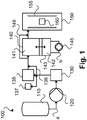
- schematically shows a hot isostatic pressing plant according to the invention in a preferred embodiment.
- In
Fig. 1 , a hot isostaticpressing plant 100 according to the invention in a preferred embodiment is schematically shown. Such plant can be used and be adapted for carrying out a method for operating a hot isostatic pressing plant according to the present invention. - In a (liquefied)
gas storage 110 gas, preferably argon (or nitrogen), can be stored. The (liquefied) gas, denoted by reference numeral a, can be pumped by means of a (cryogenic)pump 120 to a vaporizer 130 (which also can be used as a buffer storage) in order to gasify the (liquefied) gas. Further, the gas is proceeded to aconstant pressure accumulator 140 viabypass line 136 bypassing acompressor 135. - If needed, e.g., if additional pressure has to be applied in order to compensate losses,
compressor 135 can be used. Also, acompressor feed buffer 137 can be used between thevaporizer 130 and thecompressor 135, if required. - The
constant pressure accumulator 140 is formed as a hydraulically operated constant pressure accumulator in the form of a piston accumulator. Theconstant pressure accumulator 140 comprises astorage volume 141 into which the gas provided by thecompressor 135 is fed. - Further, the
constant pressure accumulator 140 comprises anoperating volume 142 which is coupled to a hydraulic circuit including ahydraulic pump 145 such that hydraulic fluid, denoted by reference numeral b, can be pumped into and taken from theoperating volume 142. - The
constant pressure accumulator 140 further comprises a movable (indicated by a double arrow)piston 143 dividing thestorage volume 141 from theoperating volume 142. Increasing the operating volume by means of pumping hydraulic fluid into it decreases thestorage volume 141. - By that, the pressure of gas stored in the
storage volume 141 can be maintained constant when gas is taken out from thestorage volume 141. In thestorage volume 141 of the constant pressure accumulator 140 a pressure of the gas of up to 600 bar and more can be provided. - It is to be noted that the
constant pressure accumulator 140 is shown and described only schematically. Typically, different kind of inlets, outlets and valves and the like are provided and used for ordinary operation. Further, from theconstant pressure accumulator 140, in particular from thestorage volume 141, the gas is provided to ahigh pressure vessel 150. - In the
high pressure vessel 150 anobject 160 is provided that is to be compacted or densified by means of hot isostatic pressing.Such object 160 is only shown exemplarily and can comprise, e.g., preformed metal, ceramic or composite parts, or (metal) powder, e.g., provided in a container. - After being filled into the
high pressure vessel 150 with a certain pressure of, e.g., 600 bar, the gas in the high pressure vessel is heated, e.g., by means of aheating apparatus 155, in order to generate high pressure of, e.g., up to 2000 bar, acting onto theobject 160. By that, theobject 160 is compacted and/or densified. - It is to be noted that the
high pressure vessel 150 and theheating apparatus 155 are shown and described only schematically since the specific details and operations are not particular relevant for the present invention. - In particular due to the constant and relatively high pressure provided by the
constant pressure accumulator 140, a high availability of the hot isostaticpressing plant 100 can be achieved, in particular, compared to usual (fresh) gas buffers used instead of theconstant pressure accumulator 140. - Further, a
bypass line 149 can be used to feed gas from thevaporizer 130 and/or thecompressor 135 to thehigh pressure vessel 150, bypassing theconstant pressure accumulator 140, if required, e.g., in the case of a failure.
Claims (12)
- Method for operating a hot isostatic pressing plant (100), wherein a high pressure vessel (150) is filled with gas (a), and wherein the gas (a), after being filled into the high pressure vessel (150), is heated in order to generate high pressure acting onto an object (160) placed in the high pressure vessel (150), characterized in that the gas (a) is filled into the high pressure vessel (150) by means of a constant pressure accumulator (140).
- Method according to claim 1, wherein the constant pressure accumulator (140) is operated at a pressure of at least 100 bar, preferably of at least 300 bar, more preferably of at least 500 bar.
- Method according to claim 1 or 2, wherein the gas (a) is provided to the constant pressure accumulator (140) by means of a pump (120) and/or compressor (135).
- Method according to any of the preceding claims, wherein a hydraulically operated constant pressure accumulator is used as the constant pressure accumulator (140).
- Method according to any of the preceding claims, wherein argon or nitrogen is used as the gas (a) to be filled into the high pressure vessel (150).
- Hot isostatic pressing plant (100) comprising a high pressure vessel (150), being arranged to be filled with gas (a), and being adapted such that the gas (a), after being filled into the high pressure vessel (150), can be heated in order to generate high pressure acting onto an object (160) placed in the high pressure vessel (150), and a constant pressure accumulator (140) arranged to fill the gas (a) into the high pressure vessel (150).
- Hot isostatic pressing plant (100) according to claim 6, wherein the constant pressure (140) accumulator is arranged to be operated at a pressure of at least 100 bar, preferably of at least 300 bar, more preferably of at least 500 bar.
- Hot isostatic pressing plant (100) according to claim 6 or 7, further including a pump (120) and/or a compressor (135) arranged to provide the gas (a) to the constant pressure accumulator (140).
- Hot isostatic pressing plant (100) according to any of claims 6 to 8, wherein the constant pressure accumulator (140) is formed as a hydraulically operated constant pressure accumulator.
- Hot isostatic pressing plant (100) according to any of claims 6 to 9, arranged to be used with argon or nitrogen as the gas (a).
- Constant pressure accumulator (140) arranged for providing gas (a), preferably argon, to a high pressure vessel (150) of a hot isostatic pressing plant (100), at a pressure of at least 100 bar, preferably of at least 300 bar, more preferably of at least 500 bar.
- Constant pressure accumulator (140) according to claim 11, formed as hydraulically operated constant pressure accumulator.
Priority Applications (2)
| Application Number | Priority Date | Filing Date | Title |
|---|---|---|---|
| EP19020432.1A EP3766681A1 (en) | 2019-07-18 | 2019-07-18 | Method for operating a hot isostatic pressing plant and hot isostatic pressure plant |
| PCT/EP2020/025329 WO2021008731A1 (en) | 2019-07-18 | 2020-07-13 | Method for operating a hot isostatic pressing plant and hot isostatic pressing plant |
Applications Claiming Priority (1)
| Application Number | Priority Date | Filing Date | Title |
|---|---|---|---|
| EP19020432.1A EP3766681A1 (en) | 2019-07-18 | 2019-07-18 | Method for operating a hot isostatic pressing plant and hot isostatic pressure plant |
Publications (1)
| Publication Number | Publication Date |
|---|---|
| EP3766681A1 true EP3766681A1 (en) | 2021-01-20 |
Family
ID=67438277
Family Applications (1)
| Application Number | Title | Priority Date | Filing Date |
|---|---|---|---|
| EP19020432.1A Withdrawn EP3766681A1 (en) | 2019-07-18 | 2019-07-18 | Method for operating a hot isostatic pressing plant and hot isostatic pressure plant |
Country Status (2)
| Country | Link |
|---|---|
| EP (1) | EP3766681A1 (en) |
| WO (1) | WO2021008731A1 (en) |
Citations (5)
| Publication number | Priority date | Publication date | Assignee | Title |
|---|---|---|---|---|
| AT314212B (en) * | 1972-04-04 | 1974-03-25 | Plansee Metallwerk | Process for sintering alloys with liquid phase |
| JPH0221191A (en) * | 1988-07-07 | 1990-01-24 | Kobe Steel Ltd | Hot hydrostatic pressurizing device |
| JPH0221193A (en) * | 1988-07-07 | 1990-01-24 | Kobe Steel Ltd | Hot hydrostatic pressurizing device |
| DE102016004118A1 (en) * | 2016-04-05 | 2017-10-05 | Linde Aktiengesellschaft | Separating piston for constant pressure accumulator |
| WO2018219445A1 (en) * | 2017-05-31 | 2018-12-06 | Quintus Technologies Ab | Pressing arrangement |
-
2019
- 2019-07-18 EP EP19020432.1A patent/EP3766681A1/en not_active Withdrawn
-
2020
- 2020-07-13 WO PCT/EP2020/025329 patent/WO2021008731A1/en not_active Ceased
Patent Citations (5)
| Publication number | Priority date | Publication date | Assignee | Title |
|---|---|---|---|---|
| AT314212B (en) * | 1972-04-04 | 1974-03-25 | Plansee Metallwerk | Process for sintering alloys with liquid phase |
| JPH0221191A (en) * | 1988-07-07 | 1990-01-24 | Kobe Steel Ltd | Hot hydrostatic pressurizing device |
| JPH0221193A (en) * | 1988-07-07 | 1990-01-24 | Kobe Steel Ltd | Hot hydrostatic pressurizing device |
| DE102016004118A1 (en) * | 2016-04-05 | 2017-10-05 | Linde Aktiengesellschaft | Separating piston for constant pressure accumulator |
| WO2018219445A1 (en) * | 2017-05-31 | 2018-12-06 | Quintus Technologies Ab | Pressing arrangement |
Also Published As
| Publication number | Publication date |
|---|---|
| WO2021008731A1 (en) | 2021-01-21 |
Similar Documents
| Publication | Publication Date | Title |
|---|---|---|
| EP2396589B1 (en) | A plant for storing and supplying compressed gas | |
| EP1839975B1 (en) | Hydrogen compressor system | |
| US6202707B1 (en) | Method for displacing pressurized liquefied gas from containers | |
| KR20210070293A (en) | Methods and equipment for storing and distributing liquid hydrogen | |
| US5816090A (en) | Method for pneumatic isostatic processing of a workpiece | |
| AU2009302974B2 (en) | Method for production of an acid proof, seemless pressure vessel | |
| WO2021008731A1 (en) | Method for operating a hot isostatic pressing plant and hot isostatic pressing plant | |
| JP5130235B2 (en) | Hydrogen fuel supply method | |
| HK1247262A1 (en) | Ultra-high isostatic pressure booster or intensifier in a multi-wall multi-chamber | |
| JP2013170580A (en) | Method for compressing cryogenic medium | |
| KR102709580B1 (en) | Cryogenic reciprocating pump for generating high pressure liquid using tension, and operating method thereof | |
| JP4859711B2 (en) | Hydrogen supply station | |
| CA2949892A1 (en) | Treatment method and device using a supercritical fluid and a discharge storage volume | |
| JPH1172198A (en) | Low temperature gas recovering method of ce equipment | |
| CN106567816A (en) | Metal hydride hydrogen-pressurizing device with full-automatic multi-stage compression function | |
| US11780192B2 (en) | Pressing arrangement | |
| HK40095584A (en) | Plant for producing mechanical energy from a carrier fluid under cryogenic conditions | |
| CN119827140B (en) | A combined voltage stabilizing system suitable for valve reliability test | |
| HK40096576A (en) | Plant for producing mechanical energy from a carrier fluid under cryogenic conditions | |
| JP2007107663A (en) | Method and apparatus for transferring natural gas hydrate | |
| CN120303508A (en) | Method for regasification and distribution of natural gas | |
| JP6672544B2 (en) | Fuel gas supply system and fuel gas supply method | |
| RU2418654C1 (en) | Method of controlling gasostatic extruder gas drive and device to this end | |
| JP4738767B2 (en) | Large cryogenic liquefied gas storage system | |
| CN119123298A (en) | A mixed gas filling system and method |
Legal Events
| Date | Code | Title | Description |
|---|---|---|---|
| PUAI | Public reference made under article 153(3) epc to a published international application that has entered the european phase |
Free format text: ORIGINAL CODE: 0009012 |
|
| STAA | Information on the status of an ep patent application or granted ep patent |
Free format text: STATUS: THE APPLICATION HAS BEEN PUBLISHED |
|
| AK | Designated contracting states |
Kind code of ref document: A1 Designated state(s): AL AT BE BG CH CY CZ DE DK EE ES FI FR GB GR HR HU IE IS IT LI LT LU LV MC MK MT NL NO PL PT RO RS SE SI SK SM TR |
|
| AX | Request for extension of the european patent |
Extension state: BA ME |
|
| STAA | Information on the status of an ep patent application or granted ep patent |
Free format text: STATUS: THE APPLICATION IS DEEMED TO BE WITHDRAWN |
|
| 18D | Application deemed to be withdrawn |
Effective date: 20210721 |