EP3766660B1 - Plastic element, manufacturing device and method for manufacturing the plastic element - Google Patents
Plastic element, manufacturing device and method for manufacturing the plastic element Download PDFInfo
- Publication number
- EP3766660B1 EP3766660B1 EP20195886.5A EP20195886A EP3766660B1 EP 3766660 B1 EP3766660 B1 EP 3766660B1 EP 20195886 A EP20195886 A EP 20195886A EP 3766660 B1 EP3766660 B1 EP 3766660B1
- Authority
- EP
- European Patent Office
- Prior art keywords
- plastics material
- extruded part
- particles
- coated
- material element
- Prior art date
- Legal status (The legal status is an assumption and is not a legal conclusion. Google has not performed a legal analysis and makes no representation as to the accuracy of the status listed.)
- Active
Links
- 229920003023 plastic Polymers 0.000 title claims description 234
- 239000004033 plastic Substances 0.000 title claims description 234
- 238000004519 manufacturing process Methods 0.000 title claims description 19
- 238000000034 method Methods 0.000 title claims description 16
- 239000000463 material Substances 0.000 claims description 110
- 238000001125 extrusion Methods 0.000 claims description 88
- 239000002245 particle Substances 0.000 claims description 65
- 239000004922 lacquer Substances 0.000 claims description 41
- 239000011248 coating agent Substances 0.000 claims description 20
- 238000000576 coating method Methods 0.000 claims description 20
- 239000011888 foil Substances 0.000 claims description 16
- 239000007921 spray Substances 0.000 claims description 13
- 239000012530 fluid Substances 0.000 claims description 11
- 229910052751 metal Inorganic materials 0.000 claims description 11
- 239000002184 metal Substances 0.000 claims description 11
- 229920002635 polyurethane Polymers 0.000 claims description 10
- 239000004814 polyurethane Substances 0.000 claims description 10
- 239000000126 substance Substances 0.000 claims description 10
- 239000004800 polyvinyl chloride Substances 0.000 claims description 8
- 229910000838 Al alloy Inorganic materials 0.000 claims description 6
- 229920000915 polyvinyl chloride Polymers 0.000 claims description 6
- 239000011521 glass Substances 0.000 claims description 5
- 239000000203 mixture Substances 0.000 claims description 5
- 229910052782 aluminium Inorganic materials 0.000 claims description 4
- XAGFODPZIPBFFR-UHFFFAOYSA-N aluminium Chemical compound [Al] XAGFODPZIPBFFR-UHFFFAOYSA-N 0.000 claims description 4
- 229910052500 inorganic mineral Inorganic materials 0.000 claims description 4
- 239000011707 mineral Substances 0.000 claims description 4
- 239000000454 talc Substances 0.000 claims description 4
- 229910052623 talc Inorganic materials 0.000 claims description 4
- 229910000831 Steel Inorganic materials 0.000 claims description 3
- 239000004411 aluminium Substances 0.000 claims description 3
- 239000000919 ceramic Substances 0.000 claims description 3
- 239000010959 steel Substances 0.000 claims description 3
- 230000003362 replicative effect Effects 0.000 claims 2
- 239000005871 repellent Substances 0.000 claims 1
- 239000003973 paint Substances 0.000 description 124
- 239000011241 protective layer Substances 0.000 description 17
- 239000010410 layer Substances 0.000 description 16
- 238000007493 shaping process Methods 0.000 description 9
- 230000000694 effects Effects 0.000 description 8
- 238000002844 melting Methods 0.000 description 8
- 230000008018 melting Effects 0.000 description 8
- 238000002347 injection Methods 0.000 description 7
- 239000007924 injection Substances 0.000 description 7
- 239000000155 melt Substances 0.000 description 7
- 238000001816 cooling Methods 0.000 description 5
- 238000000465 moulding Methods 0.000 description 5
- 230000007704 transition Effects 0.000 description 5
- 238000004049 embossing Methods 0.000 description 4
- XLYOFNOQVPJJNP-UHFFFAOYSA-N water Substances O XLYOFNOQVPJJNP-UHFFFAOYSA-N 0.000 description 4
- 238000011161 development Methods 0.000 description 3
- 230000018109 developmental process Effects 0.000 description 3
- 229920001971 elastomer Polymers 0.000 description 3
- -1 etc. Substances 0.000 description 3
- 229920001187 thermosetting polymer Polymers 0.000 description 3
- 239000004952 Polyamide Substances 0.000 description 2
- 239000000654 additive Substances 0.000 description 2
- 230000000996 additive effect Effects 0.000 description 2
- 238000005452 bending Methods 0.000 description 2
- 239000003822 epoxy resin Substances 0.000 description 2
- 238000001746 injection moulding Methods 0.000 description 2
- 238000007591 painting process Methods 0.000 description 2
- 229920002647 polyamide Polymers 0.000 description 2
- 229920000647 polyepoxide Polymers 0.000 description 2
- 229920003002 synthetic resin Polymers 0.000 description 2
- 239000000057 synthetic resin Substances 0.000 description 2
- 239000002023 wood Substances 0.000 description 2
- BQCADISMDOOEFD-UHFFFAOYSA-N Silver Chemical compound [Ag] BQCADISMDOOEFD-UHFFFAOYSA-N 0.000 description 1
- 239000011149 active material Substances 0.000 description 1
- 238000007792 addition Methods 0.000 description 1
- 239000011324 bead Substances 0.000 description 1
- 230000015572 biosynthetic process Effects 0.000 description 1
- 238000005422 blasting Methods 0.000 description 1
- 229910010293 ceramic material Inorganic materials 0.000 description 1
- 238000013016 damping Methods 0.000 description 1
- 230000006735 deficit Effects 0.000 description 1
- 230000001419 dependent effect Effects 0.000 description 1
- 239000013013 elastic material Substances 0.000 description 1
- 238000003384 imaging method Methods 0.000 description 1
- 230000001678 irradiating effect Effects 0.000 description 1
- 239000007788 liquid Substances 0.000 description 1
- 238000010297 mechanical methods and process Methods 0.000 description 1
- 230000005226 mechanical processes and functions Effects 0.000 description 1
- 238000010137 moulding (plastic) Methods 0.000 description 1
- 230000003287 optical effect Effects 0.000 description 1
- 238000010422 painting Methods 0.000 description 1
- 229920003229 poly(methyl methacrylate) Polymers 0.000 description 1
- 239000004926 polymethyl methacrylate Substances 0.000 description 1
- 229910052709 silver Inorganic materials 0.000 description 1
- 239000004332 silver Substances 0.000 description 1
- 239000000758 substrate Substances 0.000 description 1
Images


Classifications
-
- B—PERFORMING OPERATIONS; TRANSPORTING
- B29—WORKING OF PLASTICS; WORKING OF SUBSTANCES IN A PLASTIC STATE IN GENERAL
- B29C—SHAPING OR JOINING OF PLASTICS; SHAPING OF MATERIAL IN A PLASTIC STATE, NOT OTHERWISE PROVIDED FOR; AFTER-TREATMENT OF THE SHAPED PRODUCTS, e.g. REPAIRING
- B29C48/00—Extrusion moulding, i.e. expressing the moulding material through a die or nozzle which imparts the desired form; Apparatus therefor
- B29C48/001—Combinations of extrusion moulding with other shaping operations
- B29C48/0021—Combinations of extrusion moulding with other shaping operations combined with joining, lining or laminating
-
- B—PERFORMING OPERATIONS; TRANSPORTING
- B29—WORKING OF PLASTICS; WORKING OF SUBSTANCES IN A PLASTIC STATE IN GENERAL
- B29C—SHAPING OR JOINING OF PLASTICS; SHAPING OF MATERIAL IN A PLASTIC STATE, NOT OTHERWISE PROVIDED FOR; AFTER-TREATMENT OF THE SHAPED PRODUCTS, e.g. REPAIRING
- B29C48/00—Extrusion moulding, i.e. expressing the moulding material through a die or nozzle which imparts the desired form; Apparatus therefor
- B29C48/03—Extrusion moulding, i.e. expressing the moulding material through a die or nozzle which imparts the desired form; Apparatus therefor characterised by the shape of the extruded material at extrusion
-
- B—PERFORMING OPERATIONS; TRANSPORTING
- B29—WORKING OF PLASTICS; WORKING OF SUBSTANCES IN A PLASTIC STATE IN GENERAL
- B29C—SHAPING OR JOINING OF PLASTICS; SHAPING OF MATERIAL IN A PLASTIC STATE, NOT OTHERWISE PROVIDED FOR; AFTER-TREATMENT OF THE SHAPED PRODUCTS, e.g. REPAIRING
- B29C48/00—Extrusion moulding, i.e. expressing the moulding material through a die or nozzle which imparts the desired form; Apparatus therefor
- B29C48/15—Extrusion moulding, i.e. expressing the moulding material through a die or nozzle which imparts the desired form; Apparatus therefor incorporating preformed parts or layers, e.g. extrusion moulding around inserts
- B29C48/154—Coating solid articles, i.e. non-hollow articles
-
- B—PERFORMING OPERATIONS; TRANSPORTING
- B29—WORKING OF PLASTICS; WORKING OF SUBSTANCES IN A PLASTIC STATE IN GENERAL
- B29C—SHAPING OR JOINING OF PLASTICS; SHAPING OF MATERIAL IN A PLASTIC STATE, NOT OTHERWISE PROVIDED FOR; AFTER-TREATMENT OF THE SHAPED PRODUCTS, e.g. REPAIRING
- B29C48/00—Extrusion moulding, i.e. expressing the moulding material through a die or nozzle which imparts the desired form; Apparatus therefor
- B29C48/25—Component parts, details or accessories; Auxiliary operations
- B29C48/285—Feeding the extrusion material to the extruder
- B29C48/288—Feeding the extrusion material to the extruder in solid form, e.g. powder or granules
- B29C48/2883—Feeding the extrusion material to the extruder in solid form, e.g. powder or granules of preformed parts, e.g. inserts fed and transported generally uninfluenced through the extruder or inserts fed directly to the die
-
- B—PERFORMING OPERATIONS; TRANSPORTING
- B29—WORKING OF PLASTICS; WORKING OF SUBSTANCES IN A PLASTIC STATE IN GENERAL
- B29K—INDEXING SCHEME ASSOCIATED WITH SUBCLASSES B29B, B29C OR B29D, RELATING TO MOULDING MATERIALS OR TO MATERIALS FOR MOULDS, REINFORCEMENTS, FILLERS OR PREFORMED PARTS, e.g. INSERTS
- B29K2075/00—Use of PU, i.e. polyureas or polyurethanes or derivatives thereof, as moulding material
-
- B—PERFORMING OPERATIONS; TRANSPORTING
- B29—WORKING OF PLASTICS; WORKING OF SUBSTANCES IN A PLASTIC STATE IN GENERAL
- B29K—INDEXING SCHEME ASSOCIATED WITH SUBCLASSES B29B, B29C OR B29D, RELATING TO MOULDING MATERIALS OR TO MATERIALS FOR MOULDS, REINFORCEMENTS, FILLERS OR PREFORMED PARTS, e.g. INSERTS
- B29K2427/00—Use of polyvinylhalogenides or derivatives thereof as filler
- B29K2427/06—PVC, i.e. polyvinylchloride
-
- B—PERFORMING OPERATIONS; TRANSPORTING
- B29—WORKING OF PLASTICS; WORKING OF SUBSTANCES IN A PLASTIC STATE IN GENERAL
- B29K—INDEXING SCHEME ASSOCIATED WITH SUBCLASSES B29B, B29C OR B29D, RELATING TO MOULDING MATERIALS OR TO MATERIALS FOR MOULDS, REINFORCEMENTS, FILLERS OR PREFORMED PARTS, e.g. INSERTS
- B29K2509/00—Use of inorganic materials not provided for in groups B29K2503/00 - B29K2507/00, as filler
-
- B—PERFORMING OPERATIONS; TRANSPORTING
- B29—WORKING OF PLASTICS; WORKING OF SUBSTANCES IN A PLASTIC STATE IN GENERAL
- B29L—INDEXING SCHEME ASSOCIATED WITH SUBCLASS B29C, RELATING TO PARTICULAR ARTICLES
- B29L2031/00—Other particular articles
- B29L2031/30—Vehicles, e.g. ships or aircraft, or body parts thereof
- B29L2031/3005—Body finishings
Definitions
- the present invention relates to a plastic element, in particular for a vehicle, as well as a manufacturing device and a method for manufacturing the plastic element.
- the IMD molded part is a plastic injection molded part that has two differently designed decorative areas.
- a glossy silver lacquer layer is applied, while in the second decorative area the plastic material of the plastic carrier is exposed on the visible side.
- a separating groove is made in the plastic material of the plastic carrier, with which the two decorative areas are optically separated from one another.
- the plastic material of the plastic carrier can, for example, be a high-gloss black substrate in which the material, such as ABS-PC or PMMA, is colored accordingly.
- such a decorative strip coated with a foil has the disadvantage that its surface can only be designed as a smooth and homogeneous surface and is correspondingly sensitive to scratches and dirt, etc., since these are immediately visible. Furthermore, the smooth and homogeneous surface of the decorative strip forms a visible and disruptive transition to a painted body part and is therefore only suitable to a limited extent as an add-on part on a vehicle, namely where a smooth and homogeneous surface is desired, e.g. with a chrome-like decorative strip.
- a decorative material in which colored synthetic resin particles are embedded in a transparent synthetic resin film and show through in color to the outside.
- the detector-active material can also be coated with a foamable PVC layer to provide damping properties.
- the GB 2 074 092 A a method and a device for equipping profiles made of elastic materials, such as rubber, with a pad of velor tapes in one operation.
- the object of the present invention is to provide a plastic element with a structured surface.
- this object is achieved by a plastic element having the features of patent claim 1 and by a method having the features of patent claim 8 and/or by a method having the features of patent claim 9 .
- a plastic element for a vehicle having the features of claim 1.
- a production device for producing a plastic element having an extrusion device with a shaping nozzle for producing the plastic element as an extruded part or as an extruded part with a base and a coating device for coating at least a section of the extruded part with a paint film, the paint film being in particular part of a paint transfer film is.
- the manufacturing device is not claimed.
- the method has the advantage that structuring can be produced on the surface of the plastic element simply by admixing the particles, with this structuring being able to be reproduced by the paint film that is subsequently applied.
- the method has the advantage that structuring can be produced by mechanical processing or structuring of the surface of the plastic element coated with the paint film, for example by means of at least one grain roller, a sprinkling device and/or a spray nozzle device.
- particles can also be added to the plastic material of the plastic element or can be omitted entirely.
- the finding/idea on which the present invention is based is to provide a plastic element with a structured surface by adding non-melting particles or particles that melt as little as possible to the extruded part, which provide the extruded part with a surface structure that is applied paint film can then be imaged and/or by structuring the surface of the extruded part provided with the paint film by a mechanical process, by sprinkling with a fluid or gas and/or by irradiating the surface of the paint film with a fluid or gas the surface of the Paint film of the extrusion part is structured.
- the plastic element having the paint film can be provided with a structured surface in each case.
- the at least one section of the extruded part coated with the paint film is structured by at least one structuring device, the structuring device being at least one grain roller.
- a grain roller has the advantage that it can provide the paint film with a defined structure.
- the at least one section of the extruded part coated with the paint film is structured by at least one structuring device, the structuring device being at least one sprinkling and/or spray nozzle device.
- a medium in particular a fluid and/or a gas, can be sprinkled and/or blasted onto the section and thereby the section or the surface of the lacquer film be structured.
- the extruded part coated with the paint film can also be provided with a surface structure very easily, with the surface structure being able to be specifically influenced by parameters such as the pressure, the distance from the paint film and/or the diameter of a liquid jet or air jet.
- the size and/or the material of the particles is/are the same or different. As a result, different effects can be achieved in the surface structuring of the coated extruded part.
- the particles are made of a non-melting plastic, for example a non-melting polyvinyl chloride, in particular a crosslinked polyvinyl chloride or a polyvinyl chloride having a high molecular weight, a non-melting combination of plastics, a mineral material, a ceramic material, talc, chalk and/or or glass made.
- a non-melting plastic for example a non-melting polyvinyl chloride, in particular a crosslinked polyvinyl chloride or a polyvinyl chloride having a high molecular weight, a non-melting combination of plastics, a mineral material, a ceramic material, talc, chalk and/or or glass made.
- the plastic or plastics that do not melt are plastics that do not melt with the plastic material of the plastic element, in particular in an extruder device, e.g. a screw extruder or piston extruder, in particular completely melt.
- the particles can form an extruded part with the plastic material with a structured surface, which can be reproduced by a paint film applied to it.
- the invention is not limited to a non-melting polyvinyl chloride as an example of a non-melting or melting plastic. Any plastic can be used which is suitable for an extrusion process and does not melt or melt or only melts or melts as little as possible during the extrusion process.
- the content of particles in the plastic material of the extruded part is preferably in a range from 20% to 30%.
- the surface of the extruded part can be formed with a sufficient structure by means of the particles, which is suitable, when the extruded part is coated with a paint film, to provide a structure similar to a painted surface or an orange peel structure.
- the particles have a diameter in a range from 40 ⁇ m to 60 ⁇ m and preferably from 45 ⁇ m to 55 ⁇ m and particularly preferably from 50 ⁇ m +/-4 ⁇ m.
- Such particles are particularly suitable for producing a surface structure of the extruded part coated with a lacquer film, which has a structure similar to a lacquered surface or an orange peel structure.
- the plastic material consists of at least one plastic.
- Polyurethane and in particular a partially crosslinked polyurethane can be used as the plastic.
- the plastic element is a vehicle panel, a vehicle molding, e.g., a roof molding or water deflector molding, a window frame or a shaft molding.
- the invention is not limited to the examples given for plastic elements as add-on parts for a vehicle.
- the add-on parts mentioned and other add-on parts for a vehicle can be made black or colored by the paint film, for example in a corresponding vehicle paint color including a white vehicle paint color.
- the paint film can be either glossy, in particular high-gloss, or matt, including matt monochromatic or matt metallic.
- the plastic element has at least one additional component, the additional component also being designed as a coated plastic element or as a coated plastic part.
- the coated plastic part can be designed as an injection molded part with at least one section having a structured surface, this section being coated with a lacquer film.
- such an additional component can be, for example, a flap element for opening and closing an opening in the roof rail. In the closed state, the flap element can form an optical transition with the rest of the roof rail and have a structured surface like the rest of the roof rail.
- a plastic element, such as a roof rail can also be designed without such an additional component or with another additional component. In the case of a roof rail, this can accordingly have another additional component or, for example, no additional component at all in addition to or as an alternative to the flap element.
- the extrusion is applied as a coating to at least a portion of the base.
- coated plastic elements which are not completely in the form of an extruded part but are only partially in the form of an extruded part or have one.
- the base is a profile made of metal and in particular of aluminium, an aluminum alloy or steel.
- a base made of aluminum or an aluminum alloy has the advantage that the finished, coated plastic element can be bent later if necessary, depending on the desired final shape.
- the particles are made of a material that does not melt, or melts as little as possible, with or in the plastic material. Due to the fact that the particles in the plastic material do not melt during production of the extruded part by extrusion in the extrusion device, or only melt slightly to a suitable degree, so that the particles can still form the surface of the extruded part with a structure that can be reproduced by a lacquer film, can have a surface texture or structuring of the extruded part coated with the paint film. This surface structuring can have, for example, an orange peel structure or a structuring that is as similar as possible to a paint finish on a body part.
- the extrusion device is a screw extruder, for example a single-screw extruder or a twin-screw extruder, or a ram extruder.
- Piston extruders can be used, for example, when there are frequent product changes or when processing particles that could lead to impairment or damage to a screw.
- a running speed of the extrusion or of the extrusion with the base from the shaping die of the extrusion device is in a range between 10 m/min to 15 m/min. This area is particularly advantageous from an economic point of view.
- the invention is not limited to this running speed range.
- the running speed can be less than 10°m/min and greater than 15°m/min, depending on the function and purpose.
- the speed of the single-screw extruder is in a range from 5 rpm to 25 rpm.
- the speed of the extruder is related to the running speed of the profile to be produced. The higher the speed, the higher the material output and the more profiles can be produced per unit of time.
- the production device has a structuring device which structures the at least one section of the extruded part coated with the lacquer film and provides or structures this, for example, with a structure that is as similar as possible to a lacquered surface. In this way, unsightly transitions between the coated plastic element later installed as an add-on part on the vehicle and an adjacent painted body part can be prevented in a targeted manner.
- the structuring device is at least one grain roller and/or at least one sprinkling and/or spray nozzle device.
- a grain roller has the advantage that it is provided with a defined or predetermined surface structure that can be easily transferred to a paint film and a constant result can be provided.
- a sprinkling device has the advantage that the paint film on the extruded part can be structured very easily and inexpensively by sprinkling it with a fluid such as water or steam.
- a spray nozzle device in turn has the advantage that a targeted structuring of the coated with the paint film extrusion part can be generated, by adjusting or varying at least one parameter such as the distance of the fluid or Gas jet, in particular air jet, to the paint film, diameter of the fluid or gas jet and / or pressure of the fluid or gas jet, the result of the structuring of the paint film can be specifically influenced and varied.
- the manufacturing device comprises a base feeding device for feeding the base to the extrusion device for coating the base with the plastic material or the mixture of the plastic material and the particles to form the plastic element as an extrusion with a base.
- the production device has a feeding device for feeding a paint transfer film, which has a paint film on a carrier layer.
- the feeding device removes the backing layer from the paint film before the paint film is fed to the extrusion device for coating the extruded part produced by means of the extrusion device by a coating device.
- the method includes the provision of at least one sprinkling and/or spray nozzle device and the sprinkling and/or jet blasting of the at least one section of the extruded part coated with the paint film by the sprinkling and/or spray nozzle device in order to structure the coated section.
- the extruded part can be made from just a plastic material or, alternatively, from a mixture of a plastic material and particles, with the particles being made from a material that has little or no contact with the plastic material during production, for example in an extrusion device , melts.
- an extruded part can be additionally structured, which already has a structuring due to the admixture of the particles in the plastic material.
- an extruded add-on part can be produced in high-gloss black or in the respective body color using a paint transfer film.
- the parts no longer have to be painted in an additional work step, as was previously the case.
- the paint-like surface can be created using a paint transfer film.
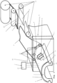
- a coated plastic element 1 is produced, which is coated with a paint film 2 of a paint transfer film 3 and has a structured surface, the structured surface for example having a structure that is as similar as possible to a painted surface or an orange peel structure.
- the plastic element 1 is produced entirely as an extruded part 23 from a plastic material 14 by means of an extrusion process.
- the plastic element can also be produced only partially as an extrusion or as an extrusion with an additional base, as in the following 3 is shown.
- a base for example a metal profile, is provided with the extruded part in at least one section, for example on its outside or visible side.
- the base is coated with the plastic material 14 by the extrusion method in the at least one section.
- the plastic material 14 consists of a plastic or a combination of at least two plastics.
- Polyurethane for example, and in particular a partially crosslinked polyurethane or a polyurethane that is not thermally deformable or that is thermally deformable as little as possible can be used as the plastic.
- the invention is not limited to polyurethane as the plastic. Any other plastic or combination of plastics can be used which is/are suitable for producing a plastic element 1 as an extruded part and in particular as an add-on part of a vehicle, which is coated with a paint film 2 of a paint transfer film 3 .
- the plastic element 1 can be designed as an add-on part for a vehicle, for example as a panel or strip, roof strip or water deflector, shaft strip, vehicle window frame, etc.
- the plastic material 14 is melted from at least one plastic, for example continuously melted, and discharged through a shaping nozzle 4 of an extrusion device 5, as in 1 greatly simplified and not drawn to scale.
- a shaping nozzle 4 as an add-on part for a vehicle in 1
- a strip 6 or screen formed as a plastic element 1.
- the plastic element 1 can also, for example, only be made partially of plastic material 14 .
- the plastic element may have a base, eg a metal profile of aluminium, an aluminum alloy or steel etc., which is coated in at least one section with the plastic material 14 by extrusion to form the plastic element as an extrusion with a base. Then the section of the plastic element coated with the plastic material by extrusion is coated on its outside with a paint film of a paint transfer film to form the finished coated plastic element.
- the paint film can be applied to the extruded part by the structuring device, such as a grain roller, a sprinkling and/or spray nozzle device, immediately or at a later point in time after leaving the extrusion device and structured by the structuring device.
- the lacquer film can also be applied to the extruded part after a subsequent cooling bath and structured by the structuring device.
- the lacquer film can be structured immediately after it has been applied or laminated onto the extruded part or in a subsequent work step.
- the aforementioned particles are mixed with the plastic material 14 of the plastic element 1 according to one embodiment of the invention.
- the particles introduced into the plastic element 1 are in 1 not shown for reasons of clarity.
- the particles consist of a material or a combination of materials which does not melt or melts as little as possible in the plastic material. Therefore, the particles form, as in subsequent 2 is shown, with the plastic material a structured surface which, when additionally coated with the lacquer film 2, forms an orange peel or a structure which is as similar as possible to a lacquered surface.
- cross-linked particles and therefore non-melting particles made of polyvinyl chloride can be used as particles, or cross-linked rubber particles, wood particles, particles made of at least one thermoset or thermoset, such as epoxy resin, polyurethane, etc., particles made of a mineral material, talc, chalk, Glass, in particular glass beads, ceramics, polyamide, metal, etc.
- the plastic material can have a proportion in a range of 20% to 30% of particles.
- the invention is not limited to this proportion in a range of 20% to 30% of particles. Depending on the function and intended use, the proportion can also be less than 20%.
- the particles can be made from the same material or at least two different materials, and can be mixed with the plastic material in the same size or diameter or in at least two different sizes or diameters.
- the particles In order to form the extruded part 23 or plastic element 1 with a structure that is as similar as possible to an orange skin or a painted surface, the particles have a diameter in a range from 40 ⁇ m to 60 ⁇ m and preferably from 45 ⁇ m to 55 ⁇ m and particularly preferably from 50 ⁇ m +/-4 ⁇ m on. Basically the size or diameter of the particles can be selected as desired, depending on the desired embossing or structure of the surface of the extruded part 23 or plastic element 1. The thicker the paint film of the paint transfer film, the weaker and softer the structure or embossing of the surface of the extruded part 23 or plastic element 1 is reproduced.
- the characteristics e.g. The larger the diameter or the size of the particles selected, the coarser the surface of the extrusion 23 or plastic element 1 provided with the paint film 2, and the smaller the diameter or size of the particles selected, the smoother the surface with the paint film 2 provided surface of the extruded part 23 or plastic element 1.
- An extrusion device 5 is used in the production of the extruded part 23 or plastic element 1 by extrusion.
- a screw extruder for example a single-screw extruder or a twin-screw extruder, or a ram extruder can be used as the extrusion device 5 .
- the pressure is generated by means of a piston. Piston extruders are mainly used when the material to be processed cannot be processed using screw extruders or when the product is to be changed frequently. However, the invention is not limited to the examples given for extrusion devices.
- the running speed of the extruded part 23 or plastic element 1 from the shaping nozzle 4 of the extrusion device 5 is in a range of preferably 10 m/min to 15 m/min. If a single-screw extruder is used as the extrusion device 5, the speed of the extrusion screw of the single-screw extruder 5 is in a range of preferably 5 rpm to 25 rpm.
- the paint transfer film 3 has an optional carrier layer 11 and an optional additional protective layer 24 in addition to the paint film 2 .
- the carrier layer 11 is arranged on the underside of the paint film 2 and the protective layer 24 on the top of the paint film 2 .
- the carrier layer 11 is pulled off the lacquer film 2 before the subsequent extrusion part is coated in front of the extrusion device 5 .
- the paint film 2 and, if present, the additional protective layer 24 of the paint transfer film 3 are preferably applied to the extrusion part 23 or the plastic element 1 by the coating device, for example immediately after leaving the shaping nozzle 4, while the extrusion part 23 or the plastic element is still warm and then the extrusion part 23 or plastic element 1 coated with the lacquer film 2 and, if present, an additional protective layer 24 is cooled.
- the extrusion part 23 or plastic element 1 coated with the paint film 2 and, if present, the additional protective layer 24 of the paint transfer film 3 can cool at room temperature or be cooled by means of an additional cooling device, not shown.
- the lacquer film 2 and, if present, the additional protective layer 24 can also be applied later to the extrusion 23 or plastic element 1, for example before, during and instead of being applied to the extruded part 23 or plastic element 1 immediately after leaving the shaping nozzle 4 /or after cooling of the extruded part 23 or plastic element 1. While the paint film 2 remains on the extruded part 23 to provide the finished plastic element 1, the protective layer 24, if present, is removed from the paint film 2 again or peeled off.
- the protective layer 24 can also be pulled off the paint film 2 at any other suitable point in time. This can be done before the extrusion die or after leaving the extrusion die, for example immediately after leaving the extrusion die, before or after structuring the paint film by the structuring device, before or after cooling the extrusion part, etc..
- the invention is not limited to the examples mentioned limited.
- the carrier layer (11) and the protective layer (24) can be made of the same material or different materials, depending on the function and intended use.
- the coating device 15 can, for example, have rollers or doctor blades, not shown, as in 1 is indicated with arrows P, by means of which the paint film 2 of the paint transfer film 3 can be applied to the extruded part 23 or plastic element 1.
- any other coating device 15 which is suitable for applying or applying the paint film 2 to at least one section of the extrusion part 23 can also be provided.
- At least one grain roller 8 is provided, which provides the surface of the extruded part 23 or plastic element 1 coated with the lacquer film 2 with, for example, an orange peel or a structure that is as similar as possible to a lacquered surface.
- the grain roller 8 has a correspondingly profiled or structured surface 9, as shown in 1 is shown in a highly simplified manner.
- a sprinkling and/or spray nozzle device 10 can be provided as the structuring device 7, as also in 1 is shown in a highly simplified manner.
- the sprinkling and/or spray nozzle device 10 is designed in such a way that the surface of the extrusion 23 or plastic element 1 coated with the lacquer film 2 of the lacquer transfer film 3 is sprinkled with a fluid or steam, e.g. water or steam, and/or with at least one or more fluids nozzles, not shown, directing a jet, in particular a fluid jet or gas jet, onto the surface coated with the paint film 2 in order to structure the surface.
- the surface structured in this way preferably has an orange skin structure or a structure which is as similar as possible to a painted surface.
- the paint transfer film 3 has the paint film 2, a protective layer 24 and a carrier layer 11, as in 1 is shown as an example.
- the paint film 2 of the paint transfer film 3 can have one layer or multiple layers, for example to achieve a specific gloss effect, in particular a high gloss effect, a metal effect, matt effect, color effect, imaging effect of the structure or embossing of the surface of the extruded part 23 or plastic element, etc . to achieve.
- the paint transfer film can also be provided with the aforementioned additional protective layer 24, which is provided on the upper side of the paint film 2 of the paint transfer film 3 in order to protect the paint film.
- this protective layer 24 can be removed again before or after the lacquer film 2 is applied to the plastic element.
- the carrier layer 11 for the paint film of the paint transfer film 3 is removed before the paint film is applied to the plastic element.
- This paint transfer film 3 is fed to the extrusion device 5 by a film feed device 12 and the carrier layer 11 is removed or pulled off the paint film 2 by the film feed device 12 before the paint film 2 is applied to the extrusion part 23 or plastic element 1 by the coating device .
- the paint film 2 of the paint transfer film 3 is in 1 indicated with a dotted line. Examples of paint transfer films, as they can be used in the invention, are, for example, from the company. Wörwag and the Manufactured by Akzo.
- the protective layer 24 is in the example in 1 indicated by a dashed line and is removed from the paint film 2, for example after leaving the extrusion device 5, for example before the paint film 2 is structured by the structuring device.
- the paint film 2 can have both at least one layer colored black and at least one layer colored in a predetermined paint color, corresponding to the paint color of a painted body part to which the plastic element 1 is subsequently attached, for example.
- both a black and a colored, including white, coated plastic element 1 can be produced as an add-on part for a vehicle.
- the paint film can be glossy, in particular high-gloss, matt and/or metallic in order to produce a correspondingly coated plastic element 1 .
- FIG. 12 is a greatly simplified, purely schematic and not to scale sectional view through the plastic element 1 coated with the paint film 2 of a paint transfer film according to FIG 1 shown.
- the plastic element 1 in this embodiment according to the invention is designed entirely as an extruded part 23 and is additionally coated with the lacquer film 2 .
- the plastic material 14 of the extruded part 23 or plastic element 1 particles 13 are admixed.
- the particles 13 consist of a material or a combination of materials which does not melt with the plastic material 14 in the extrusion device or melts only slightly with it in the extrusion device, so that a structured surface and no smooth surface is produced.
- the particles 13, as in 2 is shown, produce a structured surface with the extrusion part 23 or plastic element 1, instead of a completely smooth surface.
- the paint film 2 of the paint transfer film applied to the structured surface of the extruded part 23 or plastic element 1 forms the structured surface of the extruded part 23 or plastic element 1, so that a plastic element 1 can be produced with a surface coated with the paint film 2 which, for example has an orange skin structure or a structure that is as similar as possible to a painted surface.
- the paint film 2 of the paint transfer film is in 2 also indicated with a dotted line.
- FIG 3 shows a highly simplified, purely schematic and not to scale sectional view through a plastic element 1 coated with a paint film 2 of a paint transfer film according to a further exemplary embodiment of the invention.
- the plastic element 1 according to 3 differs from the plastic element in the 1 and 2 characterized in that the plastic element 1 is not completely made as an extrusion but only partially as an extrusion 23 from a plastic material 14 made of at least one plastic.
- the plastic element 1 in the embodiment in 3 has a base 16, e.g.
- the invention is not limited to a base 16 made of metal.
- the base 16 can also be made from any other material or combination of materials which is suitable for being coated by extrusion with a plastic material made from at least one plastic to form a plastic element 1 as an extruded part 23 with a base.
- base 16 is extruded as previously exemplified with reference to FIG 1 and 2 was described, coated with the plastic material 14 to form the extruded part 23, wherein the plastic material 14 for the later formation of a structured surface optionally additionally particles 13 can be admixed, as previously also exemplary with reference to 1 and 2 was described.
- the plastic material 14 for the later formation of a structured surface optionally additionally particles 13 can be admixed, as previously also exemplary with reference to 1 and 2 was described.
- the visible side or top of the base 16 is coated from an aluminum alloy by extrusion with the plastic material 14 made of at least one plastic.
- the plastic material 14 is additionally admixed with particles 13, for example.
- particles 13 are produced, for example in the form of small balls, with a diameter suitable or predetermined for generating a structured surface, made of a material or a combination of materials which does not melt or melts as little as possible in the plastic material.
- the particles 13 in the form of spheres can, as previously with reference to FIG 1 and 2 was described, for example, from polyvinyl chloride (PVC), cross-linked rubber, wood, from at least one duromer or thermoset, such as epoxy resin, polyurethane, etc., from a mineral material, talc, chalk, glass, ceramics, polyamide, metal, etc. .. made be.
- PVC polyvinyl chloride
- the invention is not limited to the materials mentioned for the particles.
- any other material or combination of materials can also be used which is suitable for being admixed to the plastic material for the extrusion part 23 of the plastic element in order to produce a desired surface structure.
- a paint film 2 of a paint transfer film is then applied to the outside of the surface of the base 16 of the plastic element 1 coated with the plastic material 14, as previously exemplified with reference to FIG 1 and 2 was described.
- the paint film 2 is also indicated with a dotted line.
- it can be coated with the lacquer film 23
- Extrusion part 23 of the plastic element 1 can also be structured by means of a structuring device, eg a grain roller, etc., as previously described with reference to FIG 1 and 2 was described.
- coated plastic elements 1 shown can be provided on a vehicle, for example, as a cover or strip, eg roof strip, etc.
- a coated plastic element 1 with a base 16, in particular made of an aluminum alloy, has the advantage that it can later be bent if necessary, for example to run as a roof rail along the roof and at least along one of the vehicle pillars.
- Such a cover or strip, in particular a roof strip in a vehicle can have one or more additional components as a coated plastic element 1, each as a coated plastic part or plastic element according to the 1 , 2 , or 3 are formed and preferably do not differ optically or as little as possible from the roof rail as a coated plastic element 1.
- this additional component can be, for example, a flap element for opening and closing an opening in the roof rail. The flap element can be folded into the open position, for example outwards, in order to release an opening in the roof rail, for mounting elements such as roof racks, etc. on the vehicle.
- the additional component can be like the roof rail as a coated plastic element 1, as before with reference to the Figures 1 to 3 is described, are formed.
- the additional component can be designed as a coated plastic part 17, as in 4 is indicated purely schematically and greatly simplified.
- FIG. 4 shows a sectional view of an injection mold 18 for producing a coated plastic part 17 as an additional component.
- the injection mold has two mold halves 19 , 20 . in the in 4
- the embodiment shown is a section of the inside of one of the mold halves 19 provided with a structure 21 to produce a structured surface on the plastic part 17.
- a paint film 2, which in 4 is indicated with a dotted line, inserted into the injection mold 18 and back-injected with at least one plastic 22.
- the paint film 2 is pressed against the structured inside of the mold half 19 in order to provide the plastic part 17 to be produced with a structured surface.
- the finished plastic part 17 coated with the paint film 2 can be provided with a surface structure which has a structure that is as similar as possible to an orange peel or a painted surface.
- the paint film 2 can have at least one or more layers.
- the coated plastic part 17 can be produced by a one-component injection molding process or by a multi-component injection molding process.
- add-on parts for a vehicle such as panels or strips, eg roof strips, vehicle window surrounds, etc.
- a vehicle such as panels or strips, eg roof strips, vehicle window surrounds, etc.
- the plastic element 1 can be produced as the plastic element 1 .
- the plastic element 1 and its cross section is purely exemplary and the invention is not limited thereto. Any shape and any cross-section can be produced, which can be produced in particular by an extrusion device.
- the invention is not limited to the 3 limited shown specific embodiment of the plastic element from extrusion and base.
- the base can have any profile, depending on the function and intended use.
- the extrusion can be shaped in any way or the base can be coated with it, depending on the function and intended use.
Description
Die vorliegende Erfindung betrifft ein Kunststoffelement, insbesondere für ein Fahrzeug, sowie eine Herstellvorrichtung und ein Verfahren zum Herstellen des Kunststoffelements.The present invention relates to a plastic element, in particular for a vehicle, as well as a manufacturing device and a method for manufacturing the plastic element.
Bisher werden Karosserieteile, sowie Anbauteil an einem Fahrzeug meistens lackiert. Hierbei zeigen die Oberflächen solcher Karosserielacke sowie die lackierten Oberflächen von aus Kunststoff hergestellten Anbauteilen in Abhängigkeit von dem Lackierverfahren auf der Oberfläche eine ausgeprägte Struktur, welche allgemein als sog. Orangenhaut bezeichnet wird.So far, body parts and add-on parts on a vehicle have mostly been painted. The surfaces of such body paints and the painted surfaces of add-on parts made of plastic show a pronounced structure on the surface, depending on the painting process, which is generally referred to as so-called orange peel skin.
Des Weiteren ist aus der
Eine solche mit einer Folie beschichtete Zierleiste hat jedoch den Nachteil, dass ihre Oberfläche nur als glatte und homogene Oberfläche ausgebildet werden kann und dem entsprechend empfindlich ist gegen Kratzer und Verschmutzungen usw., da diese sofort sichtbar werden. Des Weiteren bildet die glatte und homogene Oberfläche der Zierleiste einen sichtbaren und störenden Übergang zu einem lackierten Karosserieteil und eignet sich daher nur bedingt als Anbauteil bei einem Fahrzeug, nämlich da wo eine glatte und homogene Oberfläche, z.B. bei einer chromartigen Zierleiste, erwünscht ist.However, such a decorative strip coated with a foil has the disadvantage that its surface can only be designed as a smooth and homogeneous surface and is correspondingly sensitive to scratches and dirt, etc., since these are immediately visible. Furthermore, the smooth and homogeneous surface of the decorative strip forms a visible and disruptive transition to a painted body part and is therefore only suitable to a limited extent as an add-on part on a vehicle, namely where a smooth and homogeneous surface is desired, e.g. with a chrome-like decorative strip.
Aus der
Des Weiteren offenbart die
Vor diesem Hintergrund liegt der vorliegenden Erfindung die Aufgabe zugrunde, ein Kunststoffelement mit einer strukturierten Oberfläche bereitzustellen.Against this background, the object of the present invention is to provide a plastic element with a structured surface.
Erfindungsgemäß wird diese Aufgabe durch ein Kunststoffelement mit den Merkmalen des Patentanspruchs 1, und durch ein Verfahren mit den Merkmalen des Patentanspruches 8 und/oder durch ein Verfahren mit den Merkmalen des Patentanspruches 9 gelöst.According to the invention, this object is achieved by a plastic element having the features of
Ein Kunststoffelement für ein Fahrzeugmit den Merkmalen des Anspruchs 1.A plastic element for a vehicle having the features of
Das Kunststoffelement hat den Vorteil, dass es mit einer definierten Oberflächenstruktur ausgebildet werden kann. Hierdurch kann das Kunststoffelement beispielsweise an ein mit dem Kunststoffelement verbundenes Bauteil, wie z.B. ein lackiertes Karosserieteil, gezielt angepasst werden. Des Weiteren kann das Kunststoffelement vollständig als Extrusionsteil oder teilweise als Extrusionsteil ausgebildet sein. In letzterem Fall bildet das Kunststoffelement beispielsweise ein Extrusionsteil mit einer Basis.The plastic element has the advantage that it can be formed with a defined surface structure. In this way, the plastic element can be specifically adapted, for example, to a component connected to the plastic element, such as a painted body part. Furthermore, the plastic element can be designed entirely as an extrusion or partially as an extrusion. In the latter case, the plastic element forms, for example, an extrusion with a base.
Eine Herstellvorrichtung zur Herstellung eines Kunststoffelements, wobei die Herstellvorrichtung eine Extrusionsvorrichtung mit einer formgebenden Düse zum Herstellen des Kunststoffelements als Extrusionsteil oder als Extrusionsteil mit einer Basis und eine Beschichtungsvorrichtung aufweist zum Beschichten zumindest eines Abschnitts des Extrusionsteils mit einer Lackfolie, wobei die Lackfolie insbesondere Teil einer Lacktransferfolie ist. Die Herstellvorrichtung ist nicht beansprucht.A production device for producing a plastic element, the production device having an extrusion device with a shaping nozzle for producing the plastic element as an extruded part or as an extruded part with a base and a coating device for coating at least a section of the extruded part with a paint film, the paint film being in particular part of a paint transfer film is. The manufacturing device is not claimed.
Ein Verfahren zur Herstellung eines Kunststoffelements mit den Merkmalen des Anspruchs 8.A method for producing a plastic element with the features of
Das Verfahren hat den Vorteil, dass eine Strukturierung an der Oberfläche des Kunststoffelements lediglich durch Beimischen der Partikel erzeugt werden kann, wobei diese Strukturierung durch die anschließend aufgebrachte Lackfolie abgebildet werden kann.The method has the advantage that structuring can be produced on the surface of the plastic element simply by admixing the particles, with this structuring being able to be reproduced by the paint film that is subsequently applied.
Ein Verfahren zur Herstellung eines Kunststoffelements mit den Merkmalen des Anspruchs 8.A method for producing a plastic element with the features of
Das Verfahren hat den Vorteil, dass eine Strukturierung durch mechanisches Bearbeiten oder Strukturieren der Oberfläche des mit der Lackfolie beschichteten Kunststoffelements erzeugt werden kann, beispielsweise mittels wenigstens eines Narbrollers, einer Besprenkelungseinrichtung und/oder einer Spritzdüseneinrichtung. In diesem Fall kann ein Beimischen von Partikeln in das Kunststoffmaterial des Kunststoffelements zusätzlich erfolgen oder auch ganz entfallen.The method has the advantage that structuring can be produced by mechanical processing or structuring of the surface of the plastic element coated with the paint film, for example by means of at least one grain roller, a sprinkling device and/or a spray nozzle device. In this case, particles can also be added to the plastic material of the plastic element or can be omitted entirely.
Die der vorliegenden Erfindung zugrunde liegende Erkenntnis/Idee besteht darin, ein Kunststoffelement mit einer strukturierten Oberfläche zu versehen, indem dem Extrusionsteil nicht schmelzende oder so wenig wie möglich aufschmelzende Partikel beigemischt werden, die das Extrusionsteil mit einer Oberflächenstruktur versehen, die durch eine auf das Extrusionsteil aufgebrachte Lackfolie anschließend abgebildet werden kann und/oder indem die Oberfläche des mit der Lackfolie versehenen Extrusionsteils durch ein mechanisches Verfahren strukturiert wird, indem durch Besprenkeln mit einem Fluid oder Gas und/oder durch Bestrahlen der Oberfläche der Lackfolie mit einem Fluid oder Gas die Oberfläche der Lackfolie des Extrusionsteils strukturiert wird. Auf diese Weise kann dass die Lackfolie aufweisende Kunststoffelement jeweils mit einer strukturierten Oberfläche versehen werden.The finding/idea on which the present invention is based is to provide a plastic element with a structured surface by adding non-melting particles or particles that melt as little as possible to the extruded part, which provide the extruded part with a surface structure that is applied paint film can then be imaged and/or by structuring the surface of the extruded part provided with the paint film by a mechanical process, by sprinkling with a fluid or gas and/or by irradiating the surface of the paint film with a fluid or gas the surface of the Paint film of the extrusion part is structured. In this way, the plastic element having the paint film can be provided with a structured surface in each case.
Vorteilhafte Ausgestaltungen und Weiterbildungen ergeben sich aus den weiteren Unteransprüchen sowie aus der Beschreibung unter Bezugnahme auf die Figuren der Zeichnung.Advantageous refinements and developments result from the further dependent claims and from the description with reference to the figures of the drawing.
In einer erfindungsgemäßen Ausführungsform ist der wenigstens ein mit der Lackfolie beschichteter Abschnitt des Extrusionsteils durch wenigstens eine Strukturierungsvorrichtung strukturiert, wobei die Strukturierungsvorrichtung wenigstens ein Narbroller ist. Ein solcher Narbroller hat den Vorteil, dass er die Lackfolie mit einer definierten Strukturierung versehen kann.In one embodiment according to the invention, the at least one section of the extruded part coated with the paint film is structured by at least one structuring device, the structuring device being at least one grain roller. Such a grain roller has the advantage that it can provide the paint film with a defined structure.
In einer anderen erfindungsgemäßen Ausführungsform ist der wenigstens eine mit der Lackfolie beschichteten Abschnitt des Extrusionsteils durch wenigstens eine Strukturierungsvorrichtung strukturiert, wobei die Strukturierungsvorrichtung wenigstens eine Besprenkelungs- und/oder Spritzdüseneinrichtung ist. Zum Strukturieren des mit der Lackfolie beschichteten Abschnitts des Extrusionsteils kann ein Medium, insbesondere ein Fluid und/oder ein Gas, auf den Abschnitt gesprenkelt und/oder gestrahlt werden und dadurch der Abschnitt bzw. die Oberfläche der Lackfolie strukturiert werden. Auf diese Weise kann das mit der Lackfolie beschichtete Extrusionsteil ebenfalls sehr einfach mit einer Oberflächenstruktur versehen werden, wobei durch Parameter wie den Druck, den Abstand von der Lackfolie und/oder den Durchmesser eines Flüssigkeitsstrahls oder Luftstrahls die Oberflächenstruktur gezielt beeinflusst werden kann.In another embodiment according to the invention, the at least one section of the extruded part coated with the paint film is structured by at least one structuring device, the structuring device being at least one sprinkling and/or spray nozzle device. To structure the section of the extrusion coated with the lacquer film, a medium, in particular a fluid and/or a gas, can be sprinkled and/or blasted onto the section and thereby the section or the surface of the lacquer film be structured. In this way, the extruded part coated with the paint film can also be provided with a surface structure very easily, with the surface structure being able to be specifically influenced by parameters such as the pressure, the distance from the paint film and/or the diameter of a liquid jet or air jet.
Gemäß einer erfindungsgemäßen Ausführungsform ist bzw. sind die Größe und/oder das Material der Partikel gleich oder unterschiedlich. Dadurch können unterschiedliche Effekte bei der Oberflächenstrukturierung des beschichteten Extrusionsteils erzielt werden.According to an embodiment of the invention, the size and/or the material of the particles is/are the same or different. As a result, different effects can be achieved in the surface structuring of the coated extruded part.
In einer erfindungsgemäßen Ausführungsform sind die Partikel aus einem nicht aufschmelzenden Kunststoff, beispielsweise einem nicht schmelzenden Polyvinylchlorid, insbesondere einem vernetzten oder einem ein hohes Molekulargewicht aufweisenden Polyvinylchlorid, einer nicht aufschmelzenden Kombination aus Kunststoffen, einem mineralischen Werkstoff, einem keramischen Werkstoff, Talkum, Kreide und/oder Glas hergestellt. Der oder die nicht aufschmelzenden Kunststoffe sind dabei solche Kunststoffe die insbesondere in einer Extrudervorrichtung, z.B. einem Schneckenextruder oder Kolbenextruder nicht mit dem Kunststoffmaterial des Kunststoffelements mit aufschmelzen insbesondere vollständig aufschmelzen. Dadurch können die Partikel mit dem Kunststoffmaterial ein Extrusionsteil mit einer strukturierten Oberfläche bilden, welche von einer darauf applizierten Lackfolie abgebildet werden kann. Die Erfindung ist dabei nicht auf ein nicht schmelzendes Polyvinylchlorid als Beispiel für einen nicht schmelzenden oder aufschmelzenden Kunststoff beschränkt. Es kann jeder Kunststoff eingesetzt werden, welcher für ein Extrusionsverfahren geeignet ist und nicht schmilzt oder aufschmilzt oder während des Extrusionsverfahrens lediglich möglichst geringfügig schmilzt oder aufschmilzt.In one embodiment of the invention, the particles are made of a non-melting plastic, for example a non-melting polyvinyl chloride, in particular a crosslinked polyvinyl chloride or a polyvinyl chloride having a high molecular weight, a non-melting combination of plastics, a mineral material, a ceramic material, talc, chalk and/or or glass made. The plastic or plastics that do not melt are plastics that do not melt with the plastic material of the plastic element, in particular in an extruder device, e.g. a screw extruder or piston extruder, in particular completely melt. As a result, the particles can form an extruded part with the plastic material with a structured surface, which can be reproduced by a paint film applied to it. The invention is not limited to a non-melting polyvinyl chloride as an example of a non-melting or melting plastic. Any plastic can be used which is suitable for an extrusion process and does not melt or melt or only melts or melts as little as possible during the extrusion process.
In einer weiteren erfindungsgemäßen Ausführungsform ist der Gehalt an Partikeln in dem Kunststoffmaterial des Extrusionsteils vorzugsweise in einem Bereich von 20% bis 30%. Dadurch kann mittels der Partikel die Oberfläche des Extrusionsteils mit einer ausreichenden Strukturierung ausgebildet werden, die geeignet ist, wenn das Extrusionsteil mit einer Lackfolie beschichtet wird, eine einer lackierten Oberfläche ähnliche Struktur oder Orangenhautstruktur bereitzustellen.In a further embodiment according to the invention, the content of particles in the plastic material of the extruded part is preferably in a range from 20% to 30%. As a result, the surface of the extruded part can be formed with a sufficient structure by means of the particles, which is suitable, when the extruded part is coated with a paint film, to provide a structure similar to a painted surface or an orange peel structure.
In einer anderen erfindungsgemäßen Ausführungsform weisen die Partikel einen Durchmesser in einem Bereich von 40µm bis 60µm und vorzugsweise von 45µm bis 55µm und besonders bevorzugt von 50µm +/-4µm auf. Solche Partikel eigenen sich besonders zur Erzeugung einer Oberflächenstruktur des mit einer Lackfolie beschichteten Extrusionsteils, welches eine einer lackierten Oberfläche ähnliche Struktur oder Orangenhautstruktur aufweist.In another embodiment of the invention, the particles have a diameter in a range from 40 μm to 60 μm and preferably from 45 μm to 55 μm and particularly preferably from 50 μm +/-4 μm. Such particles are particularly suitable for producing a surface structure of the extruded part coated with a lacquer film, which has a structure similar to a lacquered surface or an orange peel structure.
In einer weiteren erfindungsgemäßen Ausführungsform besteht das Kunststoffmaterial aus wenigstens einem Kunststoff. Als Kunststoff kann Polyurethan und insbesondere ein teilvernetztes Polyurethan eingesetzt werden.In a further embodiment according to the invention, the plastic material consists of at least one plastic. Polyurethane and in particular a partially crosslinked polyurethane can be used as the plastic.
In einer anderen erfindungsgemäßen Ausführungsform ist das Kunststoffelement eine Fahrzeugblende, eine Fahrzeugleiste, z.B. eine Dachleiste oder Wasserabweiserleiste, eine Fenstereinfassung oder eine Schachtleiste. Die Erfindung ist auf die genannten Beispiele für Kunststoffelemente als Anbauteile für ein Fahrzeug nicht beschränkt. Die genannten Anbauteile sowie weitere Anbauteile für ein Fahrzeug können durch die Lackfolie sowohl in schwarz als auch farbig, beispielsweise in einer entsprechenden Fahrzeuglackierungsfarbe einschließlich einer weißen Fahrzeuglackierungsfarbe, ausgebildet werden. Die Lackfolie kann sowohl glänzend, insbesondere hochglänzend, als auch matt, einschließlich matt-einfarbig oder matt-metallic, ausgebildet sein.In another embodiment of the invention, the plastic element is a vehicle panel, a vehicle molding, e.g., a roof molding or water deflector molding, a window frame or a shaft molding. The invention is not limited to the examples given for plastic elements as add-on parts for a vehicle. The add-on parts mentioned and other add-on parts for a vehicle can be made black or colored by the paint film, for example in a corresponding vehicle paint color including a white vehicle paint color. The paint film can be either glossy, in particular high-gloss, or matt, including matt monochromatic or matt metallic.
Gemäß einer Ausführungsform der Erfindung weist das Kunststoffelement wenigstens ein Zusatzbauteil auf, wobei das Zusatzbauteil ebenfalls als beschichtetes Kunststoffelement oder als beschichtetes Kunststoffteil ausgebildet ist. Das beschichtete Kunststoffteil kann hierbei als Spritzgussteil mit wenigstens einem Abschnitt mit einer strukturierten Oberfläche ausgebildet sein, wobei dieser Abschnitt mit einer Lackfolie beschichtet ist. Ein solches Zusatzbauteil kann bei einer Dachleiste als beschichtetem Kunststoffelement beispielsweise ein Klappenelement zum Öffnen und Verschließen einer Öffnung in der Dachleiste sein. In geschlossenem Zustand kann das Klappenelement dabei einen optischen Übergang mit der übrigen Dachleiste bilden und eine strukturierte Oberfläche wie die übrige Dachleiste aufweisen. Ebenso kann ein Kunststoffelement, wie z.B. eine Dachleiste, auch ohne ein solches Zusatzbauteil ausgebildet sein oder mit einem anderen Zusatzbauteil. Im Falle einer Dachleiste kann diese dem entsprechend zusätzlich oder alternativ zu dem Klappenelement ein anderes Zusatzbauteil oder z.B. überhaupt kein Zusatzbauteil aufweisen.According to one embodiment of the invention, the plastic element has at least one additional component, the additional component also being designed as a coated plastic element or as a coated plastic part. The coated plastic part can be designed as an injection molded part with at least one section having a structured surface, this section being coated with a lacquer film. In the case of a roof rail as a coated plastic element, such an additional component can be, for example, a flap element for opening and closing an opening in the roof rail. In the closed state, the flap element can form an optical transition with the rest of the roof rail and have a structured surface like the rest of the roof rail. A plastic element, such as a roof rail, can also be designed without such an additional component or with another additional component. In the case of a roof rail, this can accordingly have another additional component or, for example, no additional component at all in addition to or as an alternative to the flap element.
In einer weiteren Ausführungsform der Erfindung ist das Extrusionsteil als eine Beschichtung auf zumindest einem Abschnitt der Basis aufgebracht. Dadurch können auch beschichtete Kunststoffelemente hergestellt werden, die nicht vollständig als ein Extrusionsteil ausgebildet sind sondern lediglich teilweise als ein Extrusionsteil ausgebildet sind oder dieses aufweisen.In another embodiment of the invention, the extrusion is applied as a coating to at least a portion of the base. As a result, it is also possible to produce coated plastic elements which are not completely in the form of an extruded part but are only partially in the form of an extruded part or have one.
In einer Ausführungsform der Erfindung ist die Basis ein Profil aus Metall und insbesondere aus Aluminium, einer Aluminiumlegierung oder Stahl ist. Eine Basis aus Aluminium oder einer Aluminiumlegierung hat den Vorteil, dass das fertige beschichtete Kunststoffelement später je nach gewünschter Endform bei Bedarf zurechtgebogen werden kann.In one embodiment of the invention, the base is a profile made of metal and in particular of aluminium, an aluminum alloy or steel. A base made of aluminum or an aluminum alloy has the advantage that the finished, coated plastic element can be bent later if necessary, depending on the desired final shape.
Gemäß einer erfindungsgemäßen Ausführungsform sind die Partikel aus einem Material hergestellt, welches nicht oder so wenig wie möglich mit oder in dem Kunststoffmaterial aufschmilzt. Dadurch, dass die Partikel in dem Kunststoffmaterial bei der Herstellung des Extrusionsteils durch Extrusion in der Extrusionsvorrichtung nicht aufschmelzen oder nur geeignet geringfügig aufschmelzen, so dass die Partikel die Oberfläche des Extrusionsteils immer noch mit einer Struktur ausbilden können, die von einer Lackfolie abgebildet werden kann, kann eine Oberflächenstruktur oder -strukturierung des mit der Lackfolie beschichteten Extrusionsteils erzeugt werden. Diese Oberflächenstrukturierung kann beispielweise eine Orangenhautstruktur oder eine einer Lackierung eines Karosserieteils möglichst ähnliche Strukturierung aufweist.According to one embodiment of the invention, the particles are made of a material that does not melt, or melts as little as possible, with or in the plastic material. Due to the fact that the particles in the plastic material do not melt during production of the extruded part by extrusion in the extrusion device, or only melt slightly to a suitable degree, so that the particles can still form the surface of the extruded part with a structure that can be reproduced by a lacquer film, can have a surface texture or structuring of the extruded part coated with the paint film. This surface structuring can have, for example, an orange peel structure or a structuring that is as similar as possible to a paint finish on a body part.
In einer erfindungsgemäßen Ausführungsform ist die Extrusionsvorrichtung ein Schneckenextruder, beispielsweise ein Einschneckenextruder oder ein Doppelschneckenextruder, oder ein Kolbenextruder. Kolbenextruder können beispielsweise eingesetzt werden, wenn ein häufiger Produktwechsel erfolgt oder Partikel verarbeitet werden, die zu einer Beeinträchtigung oder Beschädigung einer Schnecke führen könnten.In one embodiment of the invention, the extrusion device is a screw extruder, for example a single-screw extruder or a twin-screw extruder, or a ram extruder. Piston extruders can be used, for example, when there are frequent product changes or when processing particles that could lead to impairment or damage to a screw.
In einer anderen erfindungsgemäßen Ausführungsform liegt eine Laufgeschwindigkeit des Extrusionsteils oder des Extrusionsteils mit der Basis aus der formgebenden Düse der Extrusionsvorrichtung in einem Bereich zwischen 10°m/min bis 15°m/min. Dieser Bereich ist besonders in wirtschaftlicher Hinsicht von Vorteil. Die Erfindung ist jedoch nicht auf diesen Bereich für die Laufgeschwindigkeit beschränkt. So kann die Laufgeschwindigkeit auf kleiner als 10°m/min und größer als 15°m/min sein, je nach Funktion und Einsatzzweck.In another embodiment of the invention, a running speed of the extrusion or of the extrusion with the base from the shaping die of the extrusion device is in a range between 10 m/min to 15 m/min. This area is particularly advantageous from an economic point of view. However, the invention is not limited to this running speed range. The running speed can be less than 10°m/min and greater than 15°m/min, depending on the function and purpose.
In einer weiteren erfindungsgemäßen Ausführungsform liegt eine Drehzahl des Einschneckenextrudes in einem Bereich von 5°U/min bis 25°U/min liegt. Bei einem Extruder hängt die Drehzahl des Extruders mit der Laufgeschwindigkeit des herzustellenden Profils zusammen. Je höher die Drehzahl umso höher ist der Materialausstoß und umso mehr Profile können pro Zeiteinheit hergestellt werden.In a further embodiment according to the invention, the speed of the single-screw extruder is in a range from 5 rpm to 25 rpm. With an extruder, the speed of the extruder is related to the running speed of the profile to be produced. The higher the speed, the higher the material output and the more profiles can be produced per unit of time.
Gemäß einer Ausführungsform weist die Herstellvorrichtung eine Strukturierungsvorrichtung auf, welche den wenigstens einen mit der Lackfolie beschichteten Abschnitt des Extrusionsteils strukturiert und diesen beispielsweise mit einer einer lackierten Oberfläche möglichst ähnlichen Struktur versieht oder strukturiert. Auf diese Weise können gezielt unschöne Übergänge zwischen dem später als Anbauteil am Fahrzeug eingebauten beschichteten Kunststoffelement und einem daran angrenzenden lackierten Karosserieteil verhindert werden.According to one embodiment, the production device has a structuring device which structures the at least one section of the extruded part coated with the lacquer film and provides or structures this, for example, with a structure that is as similar as possible to a lacquered surface. In this way, unsightly transitions between the coated plastic element later installed as an add-on part on the vehicle and an adjacent painted body part can be prevented in a targeted manner.
In einer weiteren Ausführungsform ist die Strukturierungsvorrichtung wenigstens ein Narbroller und/oder wenigstens eine Besprenkelungs- und/oder Spritzdüseneinrichtung. Ein Narbroller hat den Vorteil, dass er mit einer definierten oder vorbestimmten Oberflächenstruktur versehen ist die problemlos auf eine Lackfolie übertragen und ein konstantes Ergebnis bereitgestellt werden kann. Eine Besprenkelungseinrichtung hat den Vorteil, dass die Lackfolie auf dem Extrusionsteil sehr einfach und kostengünstig durch besprenkeln mit einem Fluid wie Wasser oder Dampf strukturiert werden kann. Eine Spritzdüseneinrichtung hat wiederum den Vorteil, dass ebenfalls eine gezielte Strukturieren des mit der Lackfolie beschichteten Extrusionsteils erzeugt werden kann, wobei durch Einstellen oder Variieren von wenigstens einem Parameter wie dem Abstand des Fluid- oder Gasstrahls, insbesondere Luftstrahls, zu der Lackfolie, Durchmesser des Fluid- oder Gasstrahls und/oder Druck des Fluid- oder Gasstrahls das Ergebnis der Strukturierung der Lackfolie gezielt beeinflusst und variiert werden kann.In a further embodiment, the structuring device is at least one grain roller and/or at least one sprinkling and/or spray nozzle device. A grain roller has the advantage that it is provided with a defined or predetermined surface structure that can be easily transferred to a paint film and a constant result can be provided. A sprinkling device has the advantage that the paint film on the extruded part can be structured very easily and inexpensively by sprinkling it with a fluid such as water or steam. A spray nozzle device in turn has the advantage that a targeted structuring of the coated with the paint film extrusion part can be generated, by adjusting or varying at least one parameter such as the distance of the fluid or Gas jet, in particular air jet, to the paint film, diameter of the fluid or gas jet and / or pressure of the fluid or gas jet, the result of the structuring of the paint film can be specifically influenced and varied.
In einer Ausführungsform weist die Herstellvorrichtung eine Basis-Zuführungsvorrichtung auf zum Zuführen der Basis zu der Extrusionsvorrichtung zum Beschichten der Basis mit dem Kunststoffmaterial oder dem Gemisch aus dem Kunststoffmaterial und den Partikeln zum Ausbilden des Kunststoffelements als Extrusionsteil mit Basis.In one embodiment, the manufacturing device comprises a base feeding device for feeding the base to the extrusion device for coating the base with the plastic material or the mixture of the plastic material and the particles to form the plastic element as an extrusion with a base.
In einer anderen Ausführungsform weist die Herstellvorrichtung eine Zuführungsvorrichtung auf zum Zuführen einer Lacktransferfolie, welche eine Lackfolie auf einer Trägerschicht aufweist. Die Zuführungsvorrichtung entfernt die Trägerschicht von der Lackfolie bevor die Lackfolie der Extrusionsvorrichtung zuführt wird zum Beschichten des mittels der Extrusionsvorrichtung hergestellten Extrusionsteils durch eine Beschichtungsvorrichtung.In another embodiment, the production device has a feeding device for feeding a paint transfer film, which has a paint film on a carrier layer. The feeding device removes the backing layer from the paint film before the paint film is fed to the extrusion device for coating the extruded part produced by means of the extrusion device by a coating device.
Gemäß einer erfindungsgemäßen Ausführungsform weist das Verfahren das Bereitstellen wenigstens einer Besprenkelungs- und/oder Spritzdüseneinrichtung sowie das Besprenkeln und/oder Düsenstrahlen des wenigstens einen mit der Lackfolie beschichteten Abschnitts des Extrusionsteils durch die Besprenkelungs- und/oder Spritzdüseneinrichtung auf, zum Strukturieren des beschichteten Abschnitts. Das Extrusionsteil kann dabei sowohl nur aus einem Kunststoffmaterial oder auch alternativ aus einem Gemisch aus einem Kunststoffmaterial und Partikeln hergestellt sein, wobei die Partikel aus einem Material hergestellt sind, welches nicht oder so wenig wie möglich mit dem Kunststoffmaterial während der Herstellung, beispielsweise in einer Extrusionsvorrichtung, aufschmilzt. Dadurch kann beispielsweise ein Extrusionsteil zusätzlich strukturiert werden, welches bereits eine Strukturierung durch die Beimischung der Partikel in das Kunststoffmaterial aufweist.According to one embodiment of the invention, the method includes the provision of at least one sprinkling and/or spray nozzle device and the sprinkling and/or jet blasting of the at least one section of the extruded part coated with the paint film by the sprinkling and/or spray nozzle device in order to structure the coated section. The extruded part can be made from just a plastic material or, alternatively, from a mixture of a plastic material and particles, with the particles being made from a material that has little or no contact with the plastic material during production, for example in an extrusion device , melts. As a result, for example, an extruded part can be additionally structured, which already has a structuring due to the admixture of the particles in the plastic material.
Die obigen Ausgestaltungen und Weiterbildungen lassen sich, sofern sinnvoll, beliebig miteinander kombinieren. Weitere mögliche Ausgestaltungen, Weiterbildungen und Implementierungen der Erfindung umfassen auch nicht explizit genannte Kombinationen von zuvor oder im Folgenden bezüglich der Ausführungsbeispiele beschriebenen Merkmale der Erfindung. Insbesondere wird dabei der Fachmann auch Einzelaspekte als Verbesserungen oder Ergänzungen zu der jeweiligen Grundform der vorliegenden Erfindung hinzufügen.The above configurations and developments can be combined with one another as desired, insofar as this makes sense. Further possible configurations, developments and implementations of the invention also include combinations of features of the invention described above or below with regard to the exemplary embodiments that are not explicitly mentioned. In particular, the person skilled in the art will also add individual aspects as improvements or additions to the respective basic form of the present invention.
Die vorliegende Erfindung wird nachfolgend anhand der in den schematischen Figuren der Zeichnungen angegebenen Ausführungsbeispiele näher erläutert. Es zeigen dabei:
- Fig. 1
- eine Perspektivansicht eines Ablaufs der Herstellung eines beschichteten Kunststoffelements gemäß einer Ausführungsform der Erfindung;
- Fig. 2
- eine Schnittansicht des beschichteten Kunststoffelements gemäß
Fig. 1 ; - Fig. 3
- eine Schnittansicht eines beschichteten Kunststoffelements gemäß einer weiteren Ausführungsform der Erfindung; und
- Fig. 4
- eine Schnittansicht einer Spritzgussform und eines Zusatzbauteils.
- 1
- a perspective view of a process of manufacturing a coated plastic element according to an embodiment of the invention;
- 2
- a sectional view of the coated plastic element according to FIG
1 ; - 3
- a sectional view of a coated plastic element according to a further embodiment of the invention; and
- 4
- a sectional view of an injection mold and an additional component.
Die beiliegenden Zeichnungen sollen ein weiteres Verständnis der Ausführungsformen der Erfindung vermitteln. Sie veranschaulichen Ausführungsformen und dienen im Zusammenhang mit der Beschreibung der Erklärung von Prinzipien und Konzepten der Erfindung. Andere Ausführungsformen und viele der genannten Vorteile ergeben sich im Hinblick auf die Zeichnungen. Die Elemente der Zeichnungen sind nicht notwendigerweise maßstabsgetreu zueinander gezeigt.The accompanying drawings are provided to provide a further understanding of embodiments of the invention. They illustrate embodiments and, together with the description, serve to explain principles and concepts of the invention. Other embodiments and many of the foregoing advantages will become apparent by reference to the drawings. The elements of the drawings are not necessarily shown to scale with respect to one another.
In den Figuren der Zeichnung sind gleiche, funktionsgleiche und gleich wirkende Elemente, Merkmale und Komponenten - sofern nichts Anderes ausführt ist -jeweils mit denselben Bezugszeichen versehen.In the figures of the drawing, elements, features and components that are the same in function and have the same effect are provided with the same reference symbols unless otherwise stated.
In
Wir zuvor beschrieben werden Karosserieteile, sowie Anbauteil an einem Fahrzeug bisher in der Regel lackiert. Die Oberflächen solcher Karosserielacke bei einem Fahrzeug sowie die lackierten Oberflächen von aus Kunststoff hergestellten Anbauteilen zeigen in Abhängigkeit von dem Lackierverfahren auf der Oberfläche eine ausgeprägte Struktur. Im allgemeinen Sprachgebrauch wird diese Struktur in Fachkreisen als sog. Orangenhaut bezeichnet.As described above, body parts and add-on parts on a vehicle have usually been painted up to now. The surfaces of such bodywork paints on a vehicle and the painted surfaces of add-on parts made of plastic show a pronounced structure on the surface depending on the painting process. In general usage, this structure is referred to in specialist circles as the so-called orange peel.
Statt des Lackierens beispielsweise von Anbauteilen, wie Blenden oder Leisten, Dachträgern usw., kann ein extrudiertes Anbauteil in hochglanzschwarz oder auch in dem jeweiligen Karosseriefarbton mittels einer Lacktransferfolie hergestellt werden. In diesem Fall müssen die Teile nicht mehr in einem zusätzlichen Arbeitsgang wie bisher lackiert werden. Stattdessen kann die lackartige Oberfläche durch eine Lacktransferfolie erzeugt werden.Instead of painting add-on parts, such as covers or strips, roof racks, etc., an extruded add-on part can be produced in high-gloss black or in the respective body color using a paint transfer film. In this case, the parts no longer have to be painted in an additional work step, as was previously the case. Instead, the paint-like surface can be created using a paint transfer film.
Bedingt durch das Herstellungsverfahren bei welchem die jeweilige Lackfolie der Lacktransferfolien mittels Walzen oder einem Rakel aufgebracht werden, weisen diese Lackfolien jedoch eine glatte und sehr homogene Oberfläche auf. Wird daher ein Anbauteil mit einer solchen Lackfolie versehen und an einem Fahrzeug verbaut, so fällt das mit der Lackfolie versehene Anbauteil gegenüber der übrigen lackierten Umgebung des Fahrzeugs aufgrund seiner glatten Oberfläche auf. Dadurch entsteht ein ungleichmäßiges Erscheinungsbild des Fahrzeugs mit unerwünschten Übergängen zwischen dem jeweiligen mit einer Lackfolie beschichteten Anbauteil und einem jeweils lackierten Karosserieteil.However, due to the manufacturing process in which the respective paint film of the paint transfer films is applied by means of rollers or a doctor blade, these paint films have a smooth and very homogeneous surface. Therefore, if an add-on part is provided with such a paint film and installed on a vehicle, the add-on part provided with the paint film stands out from the rest of the painted surroundings of the vehicle because of its smooth surface. This results in an uneven appearance of the vehicle with undesirable transitions between the respective add-on part coated with a paint film and a painted body part.
Daher wird gemäß der Erfindung ein beschichtetes Kunststoffelement 1 hergestellt, welches mit einer Lackfolie 2 einer Lacktransferfolie 3 beschichtet ist und eine strukturierte Oberfläche aufweist, wobei die strukturierte Oberfläche beispielsweise eine einer lackierten Oberfläche möglichst ähnliche Struktur oder Orangenhautstruktur aufweist.Therefore, according to the invention, a coated
Wie in der erfindungsgemäßen Ausführungsform in
Das Kunststoffmaterial 14 besteht dabei aus einem Kunststoff oder einer Kombination aus wenigstens zwei Kunststoffen. Als Kunststoff kann dabei beispielsweise Polyurethan und insbesondere ein teilvernetztes Polyurethan oder ein nicht thermisch oder möglichst geringfügig thermisch verformbares Polyurethan verwendet werden. Die Erfindung ist jedoch nicht auf Polyurethan als Kunststoff beschränkt. Es kann jeder andere Kunststoff oder Kombination aus Kunststoffen verwendet werden, der bzw. die geeignet sind zur Herstellung eines Kunststoffelements 1 als Extrusionsteil und insbesondere Anbauteils eines Fahrzeugs, welches mit einer Lackfolie 2 einer Lacktransferfolie 3 beschichtet wird.The
Das Kunststoffelement 1 kann dabei als Anbauteil für ein Fahrzeug, beispielsweise als Blende oder Leiste, Dachleiste oder Wasserabweiser, Schachtleiste, Fahrzeugscheibeneinfassung usw., ausgebildet sein.The
Bei der Extrusion wird das Kunststoffmaterial 14 aus wenigstens einem Kunststoff aufgeschmolzen, z.B. kontinuierlich aufgeschmolzen, und durch eine formgebende Düse 4 einer Extrusionsvorrichtung 5 ausgetragen, wie in
In einer alternativen Ausführungsform, wie sie in nachfolgender
Um das Kunststoffelement 1 auf seiner mit einer Lackfolie zu beschichtenden Außenseite mit einer einer lackierten Oberfläche möglichst ähnlichen Struktur oder Orangenhautstruktur zu versehen, werden gemäß einer Ausführungsform der Erfindung dem Kunststoffmaterial 14 des Kunststoffelements 1 die zuvor genannten Partikel zugemischt. Die in das Kunststoffelement 1 eingebrachten Partikel sind in
Die Partikel bestehen aus einem Material oder einer Materialkombination welche nicht oder so wenig wie möglich in dem Kunststoffmaterial schmilzt oder aufschmilzt. Daher bilden die Partikel, wie in nachfolgender
Bei dieser Ausführungsform zur Erzeugung einer Orangenhautstruktur oder einer einer lackierten Oberfläche möglichst ähnlichen Struktur auf dem Extrudat bzw. Kunststoffelement 1 wird der Kunststoff oder das Kunststoffmaterial 14 unterhalb der Lackfolie 2 durch wenigstens ein geeignetes Additiv in Form von nicht oder nur geringfügig aufschmelzenden Partikeln modifiziert. Dieser Partikelzusatz erzeugt im Kunststoff eine Oberflächenstruktur, welche sich derart auf die Lackfolie 2 der Lacktransferfolie 3 nach dem Beschichten des Kunststoffelements 1 mit dieser Folie 2 überträgt oder abbildet, wie in nachfolgender
Als Partikel können beispielsweise vernetzte Partikel und damit nicht aufschmelzende Partikel aus Polyvinylchlorid (PVC) verwendet werden oder vernetzte Gummipartikel, Holzpartikel, Partikel aus wenigstens einem Duromer oder Duroplast, wie z.B. Epoxidharz, Polyurethan usw., Partikel aus einem mineralischen Werkstoff, Talkum, Kreide, Glas, insbesondere Glaskugeln, Keramik, Polyamid, Metall usw.. Beispielsweise kann das Kunststoffmaterial einen Anteil in einem Bereich von 20% bis 30% an Partikeln aufweisen. Die Erfindung ist jedoch auf diesen Anteil in einem Bereich von 20% bis 30% an Partikeln nicht beschränkt. Je nach Funktion und Einsatzzweck kann der Anteil auch kleiner als 20% sein. Die Partikel können dabei aus demselben Material oder wenigstens zwei unterschiedlichen Materialien hergestellt sein, sowie dieselbe Größe oder Durchmesser oder in wenigstens zwei unterschiedlichen Größen oder Durchmessern dem Kunststoffmaterial beigemischt werden.For example, cross-linked particles and therefore non-melting particles made of polyvinyl chloride (PVC) can be used as particles, or cross-linked rubber particles, wood particles, particles made of at least one thermoset or thermoset, such as epoxy resin, polyurethane, etc., particles made of a mineral material, talc, chalk, Glass, in particular glass beads, ceramics, polyamide, metal, etc. For example, the plastic material can have a proportion in a range of 20% to 30% of particles. However, the invention is not limited to this proportion in a range of 20% to 30% of particles. Depending on the function and intended use, the proportion can also be less than 20%. The particles can be made from the same material or at least two different materials, and can be mixed with the plastic material in the same size or diameter or in at least two different sizes or diameters.
Um das Extrusionsteil 23 bzw. Kunststoffelement 1 mit einer einer Orangenhaut oder einer einer lackierten Oberfläche möglichst ähnliche Struktur auszubilden, weisen die Partikel beispielsweise einen Durchmesser in einem Bereich von 40µm bis 60µm und vorzugsweise von 45µm bis 55µm und besonders bevorzugt von 50µm +/-4µm auf. Grundsätzlich ist die Größe oder der Durchmesser der Partikel beliebig wählbar, je nach gewünschter herzustellender Prägung oder Struktur der Oberfläche des Extrusionsteils 23 bzw. Kunststoffelements 1. Je dicker die Lackfolie der Lacktransferfolie umso schwächer und weicher wird die Struktur oder Prägung der Oberfläche des Extrusionsteils 23 bzw. Kunststoffelements 1 abgebildet. Umso dünner die Lacktransferfolie umso stärker und schärfer wird die Struktur oder Prägung der Oberfläche des Extrusionsteils 23 bzw. Kunststoffelements 1 wiederum abgebildet. Dem entsprechend kann durch die Wahl der Größe oder des Durchmessers der Partikel und der Dicke der Lackfolie, die Struktur der mit der Lackfolie versehenen Oberfläche des Extrusionsteils 23 bzw. Kunststoffelements gezielt eingestellt werden.In order to form the
Die Ausprägung z.B. der Orangenhaut oder der einer lackierten Oberfläche möglichst ähnlichen Struktur kann durch die Wahl des Durchmessers oder der Größe der Partikel gezielt beeinflusst oder eingestellt werden. Je größer der Durchmesser oder die Größe der Partikel gewählt ist, umso gröber ist die mit der Lackfolie 2 versehene Oberfläche des Extrusionsteils 23 bzw. Kunststoffelements 1 und je kleiner der Durchmesser oder die Größe der Partikel gewählt ist, umso glatter ist die mit der Lackfolie 2 versehene Oberfläche des Extrusionsteils 23 bzw. Kunststoffelements 1.The characteristics, e.g. The larger the diameter or the size of the particles selected, the coarser the surface of the
Bei der Herstellung des Extrusionsteils 23 bzw. Kunststoffelements 1 durch Extrusion wird eine Extrusionsvorrichtung 5 verwendet. Als Extrusionsvorrichtung 5 kann dabei ein Schneckenextruder, beispielsweise ein Einschneckenextruder oder ein Doppelschneckenextruder, oder ein Kolbenextruder verwendet werden. Bei dem Kolbenextruder wird der Druck mittels eines Kolbens erzeugt. Kolbenextruder werden vor allem eingesetzt, wenn sich das zu verarbeitende Material nicht mittels Schneckenextrudern verarbeiten lässt oder ein häufiger Produktwechsel durchgeführt werden soll. Die Erfindung ist jedoch auf die genannten Beispiele für Extrusionsvorrichtungen nicht beschränkt.An
Die Laufgeschwindigkeit des Extrusionsteils 23 bzw. Kunststoffelements 1 aus der formgebenden Düse 4 der Extrusionsvorrichtung 5 liegt in einem Bereich von vorzugsweise 10°m/min bis 15°m/min. Sofern ein Einschneckenextruder als Extrusionsvorrichtung 5 verwendet wird, liegt die Drehzahl der Extrusionsschnecke des Einschneckenextrudes 5 in einem Bereich von vorzugsweise 5°U/min bis 25°U/min.The running speed of the
In dem in
Wie in
Die Beschichtungsvorrichtung 15 kann beispielsweise nicht dargestellte Rollen oder Rakel aufweisen, wie in
In einer weiteren Ausführungsform der Erfindung kann zusätzlich oder alternativ zu dem Einbringen von Partikeln in das Kunststoffmaterial, das Extrusionsteil 23 bzw. Kunststoffelement 1 mit einer Orangenhaut oder mit einer einer lackierten Oberfläche möglichst ähnliche Struktur versehen werden, indem die mit der Lackfolie 2 versehene Oberfläche des Extrusionsteil 23 bzw. Kunststoffelements 1 durch eine zuvor genannte Strukturierungsvorrichtung 7 strukturiert wird.In a further embodiment of the invention, in addition or as an alternative to the introduction of particles into the plastic material, the
Als Strukturierungsvorrichtung 7 kann dabei, wie in
Des Weiteren kann als Strukturierungsvorrichtung 7 eine Besprenkelungs- und/oder Spritzdüseneinrichtung 10 vorgesehen werden, wie ebenfalls in
Die Lacktransferfolie 3 weist, wie zuvor beschrieben die Lackfolie 2, eine Schutzschicht 24 und eine Trägerschicht 11 auf, wie in
Diese Lacktransferfolie 3 wird der Extrusionsvorrichtung 5 durch eine Folien-Zuführungsvorrichtung 12 zugeführt und dabei die Trägerschicht 11 von der Lackfolie 2 durch die Folien-Zuführungsvorrichtung 12 entfernt oder abgezogen, bevor die Lackfolie 2 auf das Extrusionsteil 23 bzw. Kunststoffelement 1 durch die Beschichtungsvorrichtung aufgebracht wird. Die Lackfolie 2 der Lacktransferfolie 3 ist in
Die Lackfolie 2 kann sowohl wenigstens eine schwarz eingefärbt Schicht als auch wenigstens in einer vorbestimmten Lackfarbe eingefärbte Schicht aufweisen, entsprechend der Lackfarbe eines lackierten Karosserieteils, an welchem das Kunststoffelement 1 beispielsweise anschließend befestigt wird. Dadurch kann z.B. sowohl ein schwarzes wie auch ein farbiges, einschließlich weißes, beschichtetes Kunststoffelement 1 als Anbauteil für ein Fahrzeug hergestellt werden. Wie zuvor beschrieben kann die Lackfolie sowohl glänzend, insbesondere hochglänzend, matt und/oder metallisch ausgebildet sein, um ein entsprechend beschichtetes Kunststoffelement 1 herzustellen.The
In
Wie zuvor mit Bezug auf
Die auf der strukturierten Oberfläche des Extrusionsteils 23 bzw. Kunststoffelements 1 aufgebrachte Lackfolie 2 der Lacktransferfolie bildet dabei die strukturierte Oberfläche des Extrusionsteils 23 bzw. Kunststoffelements 1 ab, so dass ein Kunststoffelement 1 mit einer mit der Lackfolie 2 beschichtete Oberfläche erzeugt werden kann, die beispielsweise eine Orangehautstruktur oder eine einer lackierten Oberfläche möglichst ähnliche Struktur aufweist.The
Die Lackfolie 2 der Lacktransferfolie ist in
In
Das Kunststoffelement 1 gemäß
Zumindest ein Abschnitt der Basis 16 wird durch Extrusion, wie zuvor beispielhaft mit Bezug auf die
Bei dem in
Anschließend wird außen auf die mit dem Kunststoffmaterial 14 beschichtete Oberfläche der Basis 16 des Kunststoffelements 1, eine Lackfolie 2 einer Lacktransferfolie aufgebracht, wie zuvor beispielhaft mit Bezug auf die
Die in
Eine solche Blende oder Leiste, insbesondere Dachleiste bei einem Fahrzeug, kann als beschichtetes Kunststoffelement 1 ein oder mehrere Zusatzbauteile aufweisen, die jeweils als ein beschichtetes Kunststoffteil oder Kunststoffelement gemäß der
In einer alternativen Ausführungsform kann das Zusatzbauteil als beschichtetes Kunststoffteil 17 ausgebildet werden, wie in
Wie zuvor mit Bezug auf die
Wie zuvor beschrieben, können als Kunststoffelement 1 Anbauteile für ein Fahrzeug, wie Blenden oder Leisten, z.B. Dachleisten, Fahrzeugscheibeneinfassungen usw. erzeugt werden. Die in
Obwohl die vorliegende Erfindung anhand bevorzugter Ausführungsbeispiele vorstehend vollständig beschrieben wurde, ist sie darauf nicht beschränkt, sondern auf vielfältige Art und Weise modifizierbar. Die zuvor beschriebenen Ausführungsformen sind miteinander kombinierbar insbesondere einzelne Merkmale davon.Although the present invention has been fully described above on the basis of preferred exemplary embodiments, it is not restricted to them, but rather can be modified in a variety of ways. The embodiments described above can be combined with one another, in particular individual features thereof.
- 11
- Kunststoffelementplastic element
- 22
- Lackfoliepaint film
- 33
- Lacktransferfoliepaint transfer film
- 44
- Formgebende DüseShaping nozzle
- 55
- Extrusionsvorrichtungextrusion device
- 66
- Leistestrip
- 77
- Strukturierungsvorrichtungstructuring device
- 88th
- Narbrollerscarroller
- 99
- Profilierte OberflächeProfiled surface
- 1010
- Besprenkelungs- und/oder SpritzdüseneinrichtungSprinkler and/or spray nozzle device
- 1111
- Trägerschichtbacking layer
- 1212
- Folien-ZuführungsvorrichtungFoil feeding device
- 1313
- Partikelparticles
- 1414
- Kunststoffmaterialplastic material
- 1515
- Beschichtungsvorrichtungcoating device
- 1616
- BasisBase
- 1717
- beschichtetes Kunststoffteilcoated plastic part
- 1818
- Spritzgussforminjection mold
- 1919
- Formhälftemold half
- 2020
- Formhälftemold half
- 2121
- Strukturierungstructuring
- 2222
- Kunststoffplastic
- 2323
- Extrusionsteilextrusion part
- 2424
- Schutzschichtprotective layer
Claims (10)
- Plastics material element (1) for a vehicle, the plastics material element (1) being formed as an extruded part (23) or as an extruded part (23) comprising a base (16), at least a portion of the outside of the extruded part (23) being coated with a lacquer foil (2) so as to form the plastics material element (1) with a structured surface, the structured surface preferably having a structure as similar as possible to a lacquered surface, characterised in that the extruded part (23) is produced from a mixture of a plastics material substance (14) and particles (13), the particles (13) being produced from a substance which does not fuse together with the plastics material substance or does so as little as possible so as to form a structured surface of the extruded part (23), the lacquer foil (2) replicating the surface, structured by admixed particles (13), of the extruded part (23) so as to form the structured surface of the plastics material element (1).
- Plastics material element according to claim 1,
characterised
in that the surface of the lacquer foil (2) is structured by at least one structuring device (7) so as to form the structured surface of the plastics material element (1). - Plastics material element according to claim 2,
characterisedin that the lacquer foil (2) is structured mechanically by at least one pitted roller (8) as a structuring device (7); and/orin that the lacquer foil (2) is structured mechanically by at least one sprinkler and/or spray nozzle device (10) as a structuring device (7), the lacquer foil (2) being sprinkled and/or nozzle-jetted with a medium, in particular a fluid and/or a gas, so as to structure the surface of the plastics material element (1). - Plastics material element according to any of the preceding claims,
characterisedin that the sizes and/or substances of the particles (13) are the same or different; and/orin that the particles (13) are produced from polyvinylchloride, a non-fusing plastics material or combination of plastics materials, a mineral material, a ceramics material, talc, chalk and/or glass; and/orin that the proportion of particles (13) in the plastics material substance (14) of the extruded part (23) is in a range of 20% to 30%; and/orin that the particles (13) have a diameter in a range of 40 um to 60 um and preferably of 45 um to 55 um and particularly preferably of 50 um ± 4 µm. - Plastics material element according to any of the preceding claims,
characterised
in that the plastics material substance (14) consists of at least one plastics material, the plastics material being polyurethane and in particular a partially cross-linked polyurethane. - Plastics material element according to any of the preceding claims,
characterised
in that the plastics material element (1) is a vehicle cover, vehicle trim (6), in particular roof trim or water-repellent trim, a vehicle window gasket or a weather strip; in particular the plastics material element (1) having at least one additional component, the additional component likewise being formed as a coated plastics material element (1) or coated plastics material part (17), the coated plastics material part (17) being formed as an injection-moulded part having at least one portion having a structured surface, said portion being coated with a lacquer foil (2). - Plastics material element according to any of the preceding claims,
characterisedin that the extruded part (23) is applied as a coating to at least a portion of the base (16); and/orin that the base (16) is a profile made of metal and in particular of aluminium, an aluminium alloy or steel. - Method for producing a plastics material element according to any of claims 1 to 7,
characterised byproviding an extrusion device (5);providing a coating device (15);producing a plastics material element (1) as an extruded part (23) or as an extruded part (23) comprising a base (16) made from a mixture of a plastics material substance (14) and particles (13) using the extrusion device (5), the particles (13) being produced from a material which does not fuse together with the plastics material substance (14) in the extrusion device (5) or does so as little as possible;coating at least a portion of the outside of the extruded part (23) with a lacquer foil (2) using the coating device (15), the lacquer foil (2) replicating the surface, structured by admixed particles (13), of the extruded part (23) so as to form the structured surface of the plastics material element (1). - Method for producing a plastics material element according to any of claims 1 to 7,
characterised byproviding an extrusion device (5);providing a coating device (15);providing a structuring device (7);producing a plastics material element (1) as an extruded part (23) or as an extruded part (23) comprising a base (16) made from a mixture of a plastics material substance (14) and particles (13) using the extrusion device (5); coating at least a portion of the outside of the extruded part (23) with a lacquer foil (2) using the coating device (15) ; andstructuring the lacquer foil (2), of the at least one portion of the extruded part (23) which is coated with the lacquer foil (2), using the structuring device (7) so as to create the plastics material element (1) with a structured surface. - Method according to either claim 8 or claim 9,
characterised byproviding at least one sprinkler and/or spray nozzle device (10) ;sprinkling and/or nozzle-jetting the lacquer foil (2), of the at least one portion of the extruded part (23) which is coated with the lacquer foil (2), using the sprinkler and/or spray nozzle device (10) so as to structure the coated portion and form the plastics material element (1) with a structured surface.
Applications Claiming Priority (3)
| Application Number | Priority Date | Filing Date | Title |
|---|---|---|---|
| DE102015211086.9A DE102015211086B4 (en) | 2015-06-17 | 2015-06-17 | Plastic element, manufacturing device and method for producing the plastic element |
| PCT/EP2016/063725 WO2016202845A2 (en) | 2015-06-17 | 2016-06-15 | Plastic element, production device and method for producing the plastic element |
| EP16731550.6A EP3310548A2 (en) | 2015-06-17 | 2016-06-15 | Plastic element, production device and method for producing the plastic element |
Related Parent Applications (1)
| Application Number | Title | Priority Date | Filing Date |
|---|---|---|---|
| EP16731550.6A Division EP3310548A2 (en) | 2015-06-17 | 2016-06-15 | Plastic element, production device and method for producing the plastic element |
Publications (2)
| Publication Number | Publication Date |
|---|---|
| EP3766660A1 EP3766660A1 (en) | 2021-01-20 |
| EP3766660B1 true EP3766660B1 (en) | 2023-08-09 |
Family
ID=56194454
Family Applications (2)
| Application Number | Title | Priority Date | Filing Date |
|---|---|---|---|
| EP16731550.6A Pending EP3310548A2 (en) | 2015-06-17 | 2016-06-15 | Plastic element, production device and method for producing the plastic element |
| EP20195886.5A Active EP3766660B1 (en) | 2015-06-17 | 2016-06-15 | Plastic element, manufacturing device and method for manufacturing the plastic element |
Family Applications Before (1)
| Application Number | Title | Priority Date | Filing Date |
|---|---|---|---|
| EP16731550.6A Pending EP3310548A2 (en) | 2015-06-17 | 2016-06-15 | Plastic element, production device and method for producing the plastic element |
Country Status (5)
| Country | Link |
|---|---|
| EP (2) | EP3310548A2 (en) |
| CN (1) | CN107921689B (en) |
| DE (1) | DE102015211086B4 (en) |
| MX (1) | MX2017016193A (en) |
| WO (1) | WO2016202845A2 (en) |
Families Citing this family (2)
| Publication number | Priority date | Publication date | Assignee | Title |
|---|---|---|---|---|
| DE102017209457A1 (en) * | 2017-06-02 | 2018-12-06 | Faurecia Innenraum Systeme Gmbh | Method and tool for producing a vehicle interior trim part and vehicle interior trim part |
| EP3542989A1 (en) * | 2018-03-20 | 2019-09-25 | Motherson Innovations Company Limited | Plastic component and method for manufacturing the same |
Family Cites Families (7)
| Publication number | Priority date | Publication date | Assignee | Title |
|---|---|---|---|---|
| JPS53145866A (en) * | 1977-05-26 | 1978-12-19 | Aron Kasei Kk | Decorative material production method |
| DE2908487A1 (en) | 1979-03-05 | 1980-09-11 | Roehm Gmbh | EXTRUDED HOLLOW PROFILE ROD MADE OF THERMOPLASTIC PLASTIC WITH SURFACE STRUCTURE |
| CH642911A5 (en) * | 1980-03-26 | 1984-05-15 | Schlegel Corp | METHOD AND DEVICE FOR APPLYING VELOUR BANDS TO PROFILES OF ELASTIC MEASURES. |
| US7067188B1 (en) | 1999-01-21 | 2006-06-27 | Arkema | Polymeric articles having a textured surface and frosted appearance |
| DE10329938A1 (en) * | 2003-07-02 | 2005-03-17 | Röhm GmbH & Co. KG | Plastic body with a microstructured surface |
| DE102012023066A1 (en) | 2012-11-26 | 2014-05-28 | Volkswagen Aktiengesellschaft | Film-decorated plastic mold i.e. in-mold decoration mold for motor car, has first decorated portion adjoined with second decorative portion and decorative areas that are separated by partition groove in plastic material of molded portion |
| PL220970B1 (en) | 2013-03-22 | 2016-02-29 | Polska Ekstruzja Spółka Z Ograniczoną Odpowiedzialnością | Method for applying external cladding for PVC profiles and device for applying external cladding for PVC profiles |
-
2015
- 2015-06-17 DE DE102015211086.9A patent/DE102015211086B4/en active Active
-
2016
- 2016-06-15 EP EP16731550.6A patent/EP3310548A2/en active Pending
- 2016-06-15 EP EP20195886.5A patent/EP3766660B1/en active Active
- 2016-06-15 MX MX2017016193A patent/MX2017016193A/en unknown
- 2016-06-15 WO PCT/EP2016/063725 patent/WO2016202845A2/en active Application Filing
- 2016-06-15 CN CN201680048137.1A patent/CN107921689B/en active Active
Also Published As
| Publication number | Publication date |
|---|---|
| DE102015211086B4 (en) | 2023-11-02 |
| MX2017016193A (en) | 2018-06-27 |
| WO2016202845A3 (en) | 2017-02-09 |
| WO2016202845A2 (en) | 2016-12-22 |
| CN107921689B (en) | 2021-04-06 |
| CN107921689A (en) | 2018-04-17 |
| DE102015211086A1 (en) | 2016-12-22 |
| EP3766660A1 (en) | 2021-01-20 |
| EP3310548A2 (en) | 2018-04-25 |
Similar Documents
| Publication | Publication Date | Title |
|---|---|---|
| EP0630763B1 (en) | Process for preparing painted parts | |
| EP3409472A1 (en) | Vehicle cladding part and method and tool for manufacturing a vehicle cladding part | |
| DE4032160A1 (en) | Co-extruded decorative plastics trim strip - features a variable thickness of decorative layer, leading to variation of colour intensity | |
| EP3044021B1 (en) | Profiled section, especially for a motor vehicle, and method for the production thereof | |
| DE102011016757B4 (en) | Method for producing a plastic composite component | |
| DE3922224A1 (en) | PROFILE STRIP | |
| DE102007058714B4 (en) | Method for producing a component and component for a motor vehicle | |
| EP1743756A1 (en) | Method for manufacturing a composite member | |
| EP3766660B1 (en) | Plastic element, manufacturing device and method for manufacturing the plastic element | |
| EP0759351B1 (en) | Method and apparatus for manufacturing two- or more coloured dashboard foils or dashboards made therefrom | |
| DE102005028355A1 (en) | Part of interior cover of vehicle and method for its production, comprise use of specific UV-resistant synthetic materials | |
| DE102004060810A1 (en) | Plastic molding and method for its production | |
| DE102008022224A1 (en) | Method for the production of plastic mold parts with a lacquer coating, comprises areawisely connecting a hardened non-thermofoamable transfer varnish carrier with a plastic form mass on side of the adhesive layer in firmly bonded manner | |
| DE10121518B4 (en) | Process for producing a two- or multi-colored foam film | |
| EP2519390A1 (en) | Moulded skin and method for producing a moulded skin | |
| DE10322994A1 (en) | Method for producing a composite component, in particular a vehicle part, and body attachment part | |
| EP1700714A2 (en) | Method and apparatus for manufacturing profile members including a flexible decorating element | |
| DE102012203412A1 (en) | Plastic decorative part | |
| EP0726840A1 (en) | Process and device for manufacturing multilayerd products by extrusion or pultrusion and the use of the melt co-extruded with the aid of the said device | |
| DE202010003268U1 (en) | Plastic moldings made of EPP | |
| DE102004012937A1 (en) | Compound material for lining vehicle interiors, with a wood grain effect, is produced in a mold containing a film where a mass is injected or foamed behind it to force the film against a structured mold surface | |
| EP3542989A1 (en) | Plastic component and method for manufacturing the same | |
| EP2576173B1 (en) | Method for producing a moulded skin having a decoration, method for producing a vehicle interior lining part | |
| DE1948442C3 (en) | Method and device for extruding a composite film made of thermoplastics | |
| DE102020202535A1 (en) | MOTOR VEHICLE DOOR SEAL ELEMENT AND METHOD OF MANUFACTURING THE SAME |
Legal Events
| Date | Code | Title | Description |
|---|---|---|---|
| PUAI | Public reference made under article 153(3) epc to a published international application that has entered the european phase |
Free format text: ORIGINAL CODE: 0009012 |
|
| STAA | Information on the status of an ep patent application or granted ep patent |
Free format text: STATUS: REQUEST FOR EXAMINATION WAS MADE |
|
| 17P | Request for examination filed |
Effective date: 20200914 |
|
| AC | Divisional application: reference to earlier application |
Ref document number: 3310548 Country of ref document: EP Kind code of ref document: P |
|
| AK | Designated contracting states |
Kind code of ref document: A1 Designated state(s): AL AT BE BG CH CY CZ DE DK EE ES FI FR GB GR HR HU IE IS IT LI LT LU LV MC MK MT NL NO PL PT RO RS SE SI SK SM TR |
|
| GRAP | Despatch of communication of intention to grant a patent |
Free format text: ORIGINAL CODE: EPIDOSNIGR1 |
|
| STAA | Information on the status of an ep patent application or granted ep patent |
Free format text: STATUS: GRANT OF PATENT IS INTENDED |
|
| INTG | Intention to grant announced |
Effective date: 20230306 |
|
| GRAS | Grant fee paid |
Free format text: ORIGINAL CODE: EPIDOSNIGR3 |
|
| GRAA | (expected) grant |
Free format text: ORIGINAL CODE: 0009210 |
|
| STAA | Information on the status of an ep patent application or granted ep patent |
Free format text: STATUS: THE PATENT HAS BEEN GRANTED |
|
| P01 | Opt-out of the competence of the unified patent court (upc) registered |
Effective date: 20230620 |
|
| AC | Divisional application: reference to earlier application |
Ref document number: 3310548 Country of ref document: EP Kind code of ref document: P |
|
| AK | Designated contracting states |
Kind code of ref document: B1 Designated state(s): AL AT BE BG CH CY CZ DE DK EE ES FI FR GB GR HR HU IE IS IT LI LT LU LV MC MK MT NL NO PL PT RO RS SE SI SK SM TR |
|
| REG | Reference to a national code |
Ref country code: GB Ref legal event code: FG4D Free format text: NOT ENGLISH |
|
| REG | Reference to a national code |
Ref country code: CH Ref legal event code: EP |
|
| REG | Reference to a national code |
Ref country code: DE Ref legal event code: R096 Ref document number: 502016016013 Country of ref document: DE |
|
| REG | Reference to a national code |
Ref country code: IE Ref legal event code: FG4D Free format text: LANGUAGE OF EP DOCUMENT: GERMAN |
|
| REG | Reference to a national code |
Ref country code: LT Ref legal event code: MG9D |
|
| REG | Reference to a national code |
Ref country code: NL Ref legal event code: MP Effective date: 20230809 |
|
| PG25 | Lapsed in a contracting state [announced via postgrant information from national office to epo] |
Ref country code: GR Free format text: LAPSE BECAUSE OF FAILURE TO SUBMIT A TRANSLATION OF THE DESCRIPTION OR TO PAY THE FEE WITHIN THE PRESCRIBED TIME-LIMIT Effective date: 20231110 |
|
| PG25 | Lapsed in a contracting state [announced via postgrant information from national office to epo] |
Ref country code: IS Free format text: LAPSE BECAUSE OF FAILURE TO SUBMIT A TRANSLATION OF THE DESCRIPTION OR TO PAY THE FEE WITHIN THE PRESCRIBED TIME-LIMIT Effective date: 20231209 |
|
| PG25 | Lapsed in a contracting state [announced via postgrant information from national office to epo] |
Ref country code: SE Free format text: LAPSE BECAUSE OF FAILURE TO SUBMIT A TRANSLATION OF THE DESCRIPTION OR TO PAY THE FEE WITHIN THE PRESCRIBED TIME-LIMIT Effective date: 20230809 Ref country code: RS Free format text: LAPSE BECAUSE OF FAILURE TO SUBMIT A TRANSLATION OF THE DESCRIPTION OR TO PAY THE FEE WITHIN THE PRESCRIBED TIME-LIMIT Effective date: 20230809 Ref country code: PT Free format text: LAPSE BECAUSE OF FAILURE TO SUBMIT A TRANSLATION OF THE DESCRIPTION OR TO PAY THE FEE WITHIN THE PRESCRIBED TIME-LIMIT Effective date: 20231211 Ref country code: NO Free format text: LAPSE BECAUSE OF FAILURE TO SUBMIT A TRANSLATION OF THE DESCRIPTION OR TO PAY THE FEE WITHIN THE PRESCRIBED TIME-LIMIT Effective date: 20231109 Ref country code: NL Free format text: LAPSE BECAUSE OF FAILURE TO SUBMIT A TRANSLATION OF THE DESCRIPTION OR TO PAY THE FEE WITHIN THE PRESCRIBED TIME-LIMIT Effective date: 20230809 Ref country code: LV Free format text: LAPSE BECAUSE OF FAILURE TO SUBMIT A TRANSLATION OF THE DESCRIPTION OR TO PAY THE FEE WITHIN THE PRESCRIBED TIME-LIMIT Effective date: 20230809 Ref country code: LT Free format text: LAPSE BECAUSE OF FAILURE TO SUBMIT A TRANSLATION OF THE DESCRIPTION OR TO PAY THE FEE WITHIN THE PRESCRIBED TIME-LIMIT Effective date: 20230809 Ref country code: IS Free format text: LAPSE BECAUSE OF FAILURE TO SUBMIT A TRANSLATION OF THE DESCRIPTION OR TO PAY THE FEE WITHIN THE PRESCRIBED TIME-LIMIT Effective date: 20231209 Ref country code: HR Free format text: LAPSE BECAUSE OF FAILURE TO SUBMIT A TRANSLATION OF THE DESCRIPTION OR TO PAY THE FEE WITHIN THE PRESCRIBED TIME-LIMIT Effective date: 20230809 Ref country code: GR Free format text: LAPSE BECAUSE OF FAILURE TO SUBMIT A TRANSLATION OF THE DESCRIPTION OR TO PAY THE FEE WITHIN THE PRESCRIBED TIME-LIMIT Effective date: 20231110 Ref country code: FI Free format text: LAPSE BECAUSE OF FAILURE TO SUBMIT A TRANSLATION OF THE DESCRIPTION OR TO PAY THE FEE WITHIN THE PRESCRIBED TIME-LIMIT Effective date: 20230809 |
|
| PG25 | Lapsed in a contracting state [announced via postgrant information from national office to epo] |
Ref country code: PL Free format text: LAPSE BECAUSE OF FAILURE TO SUBMIT A TRANSLATION OF THE DESCRIPTION OR TO PAY THE FEE WITHIN THE PRESCRIBED TIME-LIMIT Effective date: 20230809 |