EP3409472A1 - Vehicle cladding part and method and tool for manufacturing a vehicle cladding part - Google Patents
Vehicle cladding part and method and tool for manufacturing a vehicle cladding part Download PDFInfo
- Publication number
- EP3409472A1 EP3409472A1 EP18175285.8A EP18175285A EP3409472A1 EP 3409472 A1 EP3409472 A1 EP 3409472A1 EP 18175285 A EP18175285 A EP 18175285A EP 3409472 A1 EP3409472 A1 EP 3409472A1
- Authority
- EP
- European Patent Office
- Prior art keywords
- plastic
- carrier part
- tool
- liquid curable
- vehicle interior
- Prior art date
- Legal status (The legal status is an assumption and is not a legal conclusion. Google has not performed a legal analysis and makes no representation as to the accuracy of the status listed.)
- Pending
Links
Images


Classifications
-
- B—PERFORMING OPERATIONS; TRANSPORTING
- B60—VEHICLES IN GENERAL
- B60R—VEHICLES, VEHICLE FITTINGS, OR VEHICLE PARTS, NOT OTHERWISE PROVIDED FOR
- B60R13/00—Elements for body-finishing, identifying, or decorating; Arrangements or adaptations for advertising purposes
- B60R13/02—Internal Trim mouldings ; Internal Ledges; Wall liners for passenger compartments; Roof liners
-
- B—PERFORMING OPERATIONS; TRANSPORTING
- B29—WORKING OF PLASTICS; WORKING OF SUBSTANCES IN A PLASTIC STATE IN GENERAL
- B29C—SHAPING OR JOINING OF PLASTICS; SHAPING OF MATERIAL IN A PLASTIC STATE, NOT OTHERWISE PROVIDED FOR; AFTER-TREATMENT OF THE SHAPED PRODUCTS, e.g. REPAIRING
- B29C64/00—Additive manufacturing, i.e. manufacturing of three-dimensional [3D] objects by additive deposition, additive agglomeration or additive layering, e.g. by 3D printing, stereolithography or selective laser sintering
- B29C64/10—Processes of additive manufacturing
- B29C64/106—Processes of additive manufacturing using only liquids or viscous materials, e.g. depositing a continuous bead of viscous material
- B29C64/118—Processes of additive manufacturing using only liquids or viscous materials, e.g. depositing a continuous bead of viscous material using filamentary material being melted, e.g. fused deposition modelling [FDM]
-
- B—PERFORMING OPERATIONS; TRANSPORTING
- B29—WORKING OF PLASTICS; WORKING OF SUBSTANCES IN A PLASTIC STATE IN GENERAL
- B29C—SHAPING OR JOINING OF PLASTICS; SHAPING OF MATERIAL IN A PLASTIC STATE, NOT OTHERWISE PROVIDED FOR; AFTER-TREATMENT OF THE SHAPED PRODUCTS, e.g. REPAIRING
- B29C70/00—Shaping composites, i.e. plastics material comprising reinforcements, fillers or preformed parts, e.g. inserts
- B29C70/68—Shaping composites, i.e. plastics material comprising reinforcements, fillers or preformed parts, e.g. inserts by incorporating or moulding on preformed parts, e.g. inserts or layers, e.g. foam blocks
- B29C70/78—Moulding material on one side only of the preformed part
-
- B—PERFORMING OPERATIONS; TRANSPORTING
- B29—WORKING OF PLASTICS; WORKING OF SUBSTANCES IN A PLASTIC STATE IN GENERAL
- B29C—SHAPING OR JOINING OF PLASTICS; SHAPING OF MATERIAL IN A PLASTIC STATE, NOT OTHERWISE PROVIDED FOR; AFTER-TREATMENT OF THE SHAPED PRODUCTS, e.g. REPAIRING
- B29C45/00—Injection moulding, i.e. forcing the required volume of moulding material through a nozzle into a closed mould; Apparatus therefor
- B29C45/14—Injection moulding, i.e. forcing the required volume of moulding material through a nozzle into a closed mould; Apparatus therefor incorporating preformed parts or layers, e.g. injection moulding around inserts or for coating articles
- B29C45/14778—Injection moulding, i.e. forcing the required volume of moulding material through a nozzle into a closed mould; Apparatus therefor incorporating preformed parts or layers, e.g. injection moulding around inserts or for coating articles the article consisting of a material with particular properties, e.g. porous, brittle
- B29C45/14811—Multilayered articles
-
- B—PERFORMING OPERATIONS; TRANSPORTING
- B29—WORKING OF PLASTICS; WORKING OF SUBSTANCES IN A PLASTIC STATE IN GENERAL
- B29C—SHAPING OR JOINING OF PLASTICS; SHAPING OF MATERIAL IN A PLASTIC STATE, NOT OTHERWISE PROVIDED FOR; AFTER-TREATMENT OF THE SHAPED PRODUCTS, e.g. REPAIRING
- B29C63/00—Lining or sheathing, i.e. applying preformed layers or sheathings of plastics; Apparatus therefor
-
- B—PERFORMING OPERATIONS; TRANSPORTING
- B29—WORKING OF PLASTICS; WORKING OF SUBSTANCES IN A PLASTIC STATE IN GENERAL
- B29C—SHAPING OR JOINING OF PLASTICS; SHAPING OF MATERIAL IN A PLASTIC STATE, NOT OTHERWISE PROVIDED FOR; AFTER-TREATMENT OF THE SHAPED PRODUCTS, e.g. REPAIRING
- B29C64/00—Additive manufacturing, i.e. manufacturing of three-dimensional [3D] objects by additive deposition, additive agglomeration or additive layering, e.g. by 3D printing, stereolithography or selective laser sintering
- B29C64/10—Processes of additive manufacturing
- B29C64/106—Processes of additive manufacturing using only liquids or viscous materials, e.g. depositing a continuous bead of viscous material
-
- B—PERFORMING OPERATIONS; TRANSPORTING
- B33—ADDITIVE MANUFACTURING TECHNOLOGY
- B33Y—ADDITIVE MANUFACTURING, i.e. MANUFACTURING OF THREE-DIMENSIONAL [3-D] OBJECTS BY ADDITIVE DEPOSITION, ADDITIVE AGGLOMERATION OR ADDITIVE LAYERING, e.g. BY 3-D PRINTING, STEREOLITHOGRAPHY OR SELECTIVE LASER SINTERING
- B33Y10/00—Processes of additive manufacturing
-
- B—PERFORMING OPERATIONS; TRANSPORTING
- B33—ADDITIVE MANUFACTURING TECHNOLOGY
- B33Y—ADDITIVE MANUFACTURING, i.e. MANUFACTURING OF THREE-DIMENSIONAL [3-D] OBJECTS BY ADDITIVE DEPOSITION, ADDITIVE AGGLOMERATION OR ADDITIVE LAYERING, e.g. BY 3-D PRINTING, STEREOLITHOGRAPHY OR SELECTIVE LASER SINTERING
- B33Y80/00—Products made by additive manufacturing
-
- B—PERFORMING OPERATIONS; TRANSPORTING
- B60—VEHICLES IN GENERAL
- B60R—VEHICLES, VEHICLE FITTINGS, OR VEHICLE PARTS, NOT OTHERWISE PROVIDED FOR
- B60R13/00—Elements for body-finishing, identifying, or decorating; Arrangements or adaptations for advertising purposes
- B60R13/02—Internal Trim mouldings ; Internal Ledges; Wall liners for passenger compartments; Roof liners
- B60R13/0206—Arrangements of fasteners and clips specially adapted for attaching inner vehicle liners or mouldings
-
- B—PERFORMING OPERATIONS; TRANSPORTING
- B29—WORKING OF PLASTICS; WORKING OF SUBSTANCES IN A PLASTIC STATE IN GENERAL
- B29L—INDEXING SCHEME ASSOCIATED WITH SUBCLASS B29C, RELATING TO PARTICULAR ARTICLES
- B29L2031/00—Other particular articles
- B29L2031/30—Vehicles, e.g. ships or aircraft, or body parts thereof
- B29L2031/3005—Body finishings
- B29L2031/302—Trim strips
-
- B—PERFORMING OPERATIONS; TRANSPORTING
- B29—WORKING OF PLASTICS; WORKING OF SUBSTANCES IN A PLASTIC STATE IN GENERAL
- B29L—INDEXING SCHEME ASSOCIATED WITH SUBCLASS B29C, RELATING TO PARTICULAR ARTICLES
- B29L2031/00—Other particular articles
- B29L2031/30—Vehicles, e.g. ships or aircraft, or body parts thereof
- B29L2031/3005—Body finishings
- B29L2031/3041—Trim panels
-
- B—PERFORMING OPERATIONS; TRANSPORTING
- B32—LAYERED PRODUCTS
- B32B—LAYERED PRODUCTS, i.e. PRODUCTS BUILT-UP OF STRATA OF FLAT OR NON-FLAT, e.g. CELLULAR OR HONEYCOMB, FORM
- B32B2605/00—Vehicles
- B32B2605/003—Interior finishings
Definitions
- the present application relates to a method for producing a vehicle interior trim part with at least one functional and / or decorative element. Moreover, the present application relates to a tool for producing the vehicle interior trim part and the vehicle interior trim part.
- the functional and / or decorative element preferably comprises a thermoplastic material.
- Vehicle interior trim parts with thermoplastic functional or decorative elements are typically manufactured by injection molding.
- this has the disadvantage of costly mold construction of complex injection molds.
- 3D printing processes enable the production of almost any type of component using CAD models.
- the publication DE 10 2014 011 230 A1 shows, for example, a device for a three-dimensional additive printing operation, in particular for large-volume Components printed by FDM (Fused Deposition Modeling).
- FDM Field Deposition Modeling
- the known 3D printing methods have the disadvantage of very long cycle times.
- the production of large components by means of 3D printing processes implies long process times, which, for example, can not meet the requirements of the automotive supply industry, in which large quantities are produced each year.
- a further object of the invention is to propose a method which makes it possible to manufacture components more simply and / or cost-effectively. Furthermore, it is an object of the invention to propose a method which reduces cycle times for producing a vehicle interior trim part with at least one functional and / or decorative element. Moreover, it is an object of the present application to propose a correspondingly advantageous vehicle interior trim part and a correspondingly advantageous tool for producing a vehicle interior trim part.
- a tool is first of all provided.
- the tool comprises at least one application unit for applying a liquid curable plastic and a receiving device having a receiving surface for receiving a support member.
- the support member is preferably fabricated in advance by a method that allows for the production of relatively large parts in large quantities and at low cost. These processes include, for example, injection molding.
- the receiving surface preferably comprises metal, more preferably steel.
- the application unit and the receiving device are movable relative to each other.
- the application unit and / or the recording device may / may be movable along at least two, preferably at least three axes, and / or be rotatable about at least one, preferably at least two axes.
- the receiving device is static and the application unit can be moved over several axes, preferably by five axes, relative to the receiving device, for example by means of an industrial robot. It is also possible that the receiving device is movable via one or more axes. In this case, a translational and / or a rotational movement can be understood as being movable.
- the carrier part has a front and a back.
- the carrier part can be bent.
- the carrier part can be flexible.
- the front side and / or the rear side may also be arched and / or curved.
- the carrier part may comprise or consist of materials such as plastic, in particular PP or ABS, and / or comprise natural materials such as wood or metals such as aluminum.
- the carrier part may comprise or consist of glass, stone, a woven fabric or a fibrous material.
- the backing member may comprise composites, for example polypropylene with natural fibers (NFPP) or a nonwoven composite.
- the carrier part is placed on the receiving surface in such a way that the front side of the carrier part rests on the receiving surface at least in regions.
- the inserted carrier part can be held or supported by the receiving surface.
- the receiving surface has a recess into which the carrier part is inserted, so that it is secured against slipping.
- the carrier part can also be oriented, positioned and / or held by bulges or other forms of the receiving surface and / or by negative pressure on the receiving surface.
- the shape of the receiving surface preferably corresponds at least in regions to the shape of the front side of the carrier part.
- the receiving surface is typically curved. Under curved is understood to mean a surface that is not exclusively planar, but may have depressions and elevations. These depressions and elevations preferably correspond at least in regions to a surface shape of the carrier part. Is this support member bent and / or the support member has a curved surface On, it can be predefined positioned and / or oriented on the receiving surface.
- the receiving surface can be structured at least partially.
- the liquid curable plastic can then be applied at least in regions to an outer edge of the carrier part and at least partially onto the structured receiving surface for forming the plastic part connected to the carrier part such that the plastic element has a structured surface which corresponds to the structured receiving surface.
- the structured surface of the plastic element represents a negative form of the structured receiving surface
- the liquid plastic thus typically shapes the structured receiving surface.
- the structured surface is preferably formed as a negative of a document surface, so that an impression of the structured surface again corresponds to the document surface.
- the surface has depressions in the form of depressions, grooves and / or grooves which typically have depths of at least 10 ⁇ m, preferably at least 50 ⁇ m and / or at most 500 ⁇ m, preferably at most 100 ⁇ m.
- the plastic penetrates into the depressions, grooves and / or furrows of the structured surface.
- the plastic forms a solidified negative of the structured surface and itself has a structured surface.
- patterns, grains and / or surface roughnesses of the original surface can be reproduced, in particular surfaces of natural materials, for example of wood, stone and / or leather, can serve as the template surface.
- a structured surface of at least one plastic element a particularly decorative vehicle interior trim part can thus be created.
- a through-hole and / or a through-hole, which runs through the carrier part can be filled with a plastic element.
- a surface of the plastic element thus applied may further have a structured decorative surface on the front of the vehicle interior trim part, as described above exhibit.
- the receiving surface in a region which is bordered by the outer edge of the through-hole or the through-bore of the carrier part placed on the receiving surface may have the above-described structured surface.
- a frame which is integrally connected to the carrier part and has on the front side of the vehicle interior trim part a structured surface which bears against the front side of the carrier part.
- the structured surface of the frame is created as described above by applying the liquid curable resin to a structured surface of the receiving surface.
- Such a frame is a typical example of a functional element that is decorative at the same time.
- the liquid curable synthetic material is applied at least in regions to a carrier part surface.
- the carrier part surface may, for example, include or be a side surface, an edge and / or the back side. If the carrier part is not completely located with its front side on the receiving surface, the carrier surface to which the liquid or curable plastic is applied may also include or form regions of the front side of the carrier part.
- Hardening may be understood as meaning both solidification and general solidification or densification.
- the applied plastic can harden, for example, by cooling, by evaporation of a solvent, by a chemical reaction of two components, by a polymerization, for example a polymerization by UV radiation, and / or a sintering.
- the vehicle interior trim part formed by the plastic element and the support part can be removed from the tool, preferably after curing of the plastic.
- the carrier part can be manufactured separately and can be injection-molded, for example. This allows a quick production of the carrier part.
- the plastic elements are generatively applied to the carrier part in the proposed method.
- the proposed method thus has the advantage that cycle times are shortened. In particular, process times are thus reduced compared to the generative production of an entire vehicle interior trim part. Furthermore, a cost for a complex mold design is minimized because the complex shapes of the plastic elements are generatively applied.
- the plastic elements may be, for example, hooks, projections for fixing the vehicle interior trim part, any holding elements, receiving elements for electronic components - such as switches, displays or lights -, frames or other decorative elements. Clip connections, clips, stiffening structures and / or bolting points are further typical plastic elements.
- Such electronic components and / or further components, which are to be fixed by the plastic elements on the support part, may preferably already be positioned prior to the additive production of the plastic part / the plastic parts in or on the support part.
- decorative plastic elements in the form of plugs and / or embellishments of holes in and / or edges on the support part are conceivable.
- through-holes which are visible on the front side of the carrier part can be decorated and / or stuffed with plastic elements.
- the plastic element may be integrally connected to the carrier part.
- a direct cohesive connection between a material of the carrier part and a material of the plastic element can be produced.
- it may also be an indirect cohesive connection, for example via one or more layers, which have been applied to the carrier part and on which in turn the plastic element is applied.
- an adhesive can be applied at least in regions to the carrier part surface, and one or more plastic elements can be generatively applied to the region or regions thus formed with adhesive.
- the surface of the support member can be at least partially processed with, for example, flames or plasma.
- by roughening the adhesion can be improved and / or an adhesion primer can be applied.
- the liquid curable plastic can be applied in layers, in particular by an additive manufacturing process, for example an FDM process or by 3D printing.
- the liquid curable plastic can be applied dropwise or in strands.
- a layered application can be carried out for example by applying a meandering strand or by applying a plurality of parallel strands of liquid curable plastic side by side in a plane. If the application takes place in droplets, the droplets can first be applied next to one another in a single plane so that they first combine on the carrier part to form one strand or several strands.
- the droplets can be arranged so that the strand formed from the droplets has a meandering shape or that several strands run parallel.
- the strands can in turn be arranged side by side so that they connect to form a layer. In this way several layers can be applied one above the other.
- the liquid curable plastic can be at least not completely cured or be melted by the heat of the hot liquid plastic applied, so that the layers and / or droplets and / or strands connect with each other.
- the plastic element forms a frame which at least partially surrounds the carrier part.
- the frame may have on a front side a structured surface, which is formed by the method described above.
- the receiving surface preferably has a groove which runs along an outer edge of the carrier part arranged on the receiving surface.
- An inner side of the channel preferably has the structured surface.
- the liquid curable plastic can be applied in layers in the groove along the outer edge of the support part, so that the frame is formed, which is materially connected to the support member.
- the liquid hardenable plastic In this case, it is possible to mold the structured surface so that the frame has a structured surface on the front side of the carrier part.
- a plastic element may alternatively or additionally also be arranged on the rear side of the carrier part.
- plastic elements which are designed as holding elements (for example hooks or pins) and which are not to be visible on the front side, an arrangement of the plastic elements on the rear side of the carrier part is preferred.
- the liquid curable plastic is typically a thermoplastic, preferably polypropylene or acrylonitrile-butadiene-styrene.
- the liquid curable plastic may consist of the same material or have the same material as the carrier part.
- a plastic with corresponding mechanical properties is used for the holding elements.
- a low-viscosity curable plastic may be preferred, which flows easily into the structured surface of the receiving part.
- the tool for producing a vehicle interior trim part comprises at least one application unit for dispensing the liquid curable synthetic material and a receiving device for receiving a three-dimensional support part.
- the application unit typically comprises a nozzle and / or an extrusion head for applying the liquid curable plastic.
- a nozzle and / or an extrusion head with a fixed round outlet opening is used.
- the diameter of the outlet opening, through which the liquid curable plastic exits from the nozzle and / or the extrusion head, can be changeable, for example by an iris diaphragm.
- the nozzle and / or the extrusion head can have different cross sections of the outlet opening, for example the outlet opening can be triangular, oval, rectangular or square.
- a vehicle interior trim part can be produced. Additional process steps may be provided.
- the vehicle interior trim part is a dashboard, a vehicle door panel, or a center console.
- the ones described above Features can also be features of the vehicle interior trim part.
- a vehicle interior trim part can be produced which comprises a carrier part and a frame bordering the carrier part, at least in regions, with the carrier part materially connected to the frame.
- the vehicle interior trim part typically has a front side and the frame preferably has a structured surface on the front side.
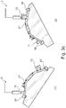
- FIG. 1a shows a tool 1 for producing a vehicle interior trim part.
- the tool 1 comprises an application unit 2 for applying a liquid curable plastic from which plastic elements can be formed according to the principle of FDM.
- the application unit 2 comprises a movable nozzle 3, through which the liquid curable plastic can be applied in a targeted manner.
- the tool 1 comprises a receiving device 2 'with a receiving surface 4, on which a carrier part 5, comprising a front side 6 and a rear side 7, is arranged.
- the receiving surface 4 is curved and corresponds to the shape of the front side 6, so that the carrier part is disposed so as to be slip-proof on the receiving surface.
- the receiving surface 4 has a channel 8 which surrounds the carrier part.
- a surface 9 of the channel 8 is structured in such a way that it images a negative mold of a wood surface structure.
- 9 furrows with a depth between 50 and 100 microns, for example 70 microns are formed on the surface.
- the surface 9 is made of steel.
- plastic elements are arranged, which were generously applied by FDM through the nozzle 3 on the support member 5. The nozzle 3 was moved by means of an industrial robot over five axes relative to the carrier part 5 and the receiving surface 4.
- One of the applied plastic elements is a frame 10, which is materially connected to the carrier part 5.
- a liquid curable plastic was layered in the surrounding the support member 5 groove 8 such that the frame surrounds the support member 5 at outer edges of the support member 5 and partially on the back 7 of the support member 5 and the channel 8 fills.
- the frame 10 is firmly bonded to the carrier part 5.
- the vehicle interior trim part having the carrier part and the generatively applied plastic element can be removed from the tool 1.
- the frame 10 has a textured surface in the areas where the liquid plastic came in contact with the structured surface 9 during application on, which corresponds to an impression of the structured surface 9. In these areas, the frame 10 thus has a wood grain.
- a holding element in the form of a hook 11 is further arranged on the support part 5.
- the hook 11 as well as the frame 10 was made generative by layered by means of FDM through the nozzle 3 liquid curable plastic.
- a through hole 12 in the carrier part 5 was filled with liquid curable plastic.
- Another holding element 13 was like the hook 11 generatively on the back 7 of the support member 5, bordering an opening 14, applied. Behind the opening 14 of the support part 5, for example, a display can be attached and held by the holding element 13. The display is thereby fixed by the holding element 13 relative to the carrier part and can be read through the opening 14 from the front or - if it is the display is a touch screen - are operated.
- the support member 5 is made of PP and the liquid curable plastic is ABS.
- the carrier part can also be made of a different material and / or comprise a different material.
- the liquid curable plastic may also be another material, for example PP.
- the material combination shown has the advantage that the liquid plastic when applied cohesively connects to the support member. If the carrier part, for example made of wood, glass or aluminum, an adhesive is applied before the application of the plastic, such an adhesive has, for example, polyamides. Subsequently, the plastic is applied to the adhesive, so that a cohesive connection between the plastic and the adhesive is formed.
- the adhesive may be, for example, a primer or an adhesive film.
- FIG. 1b essentially shows the tool of FIG. 1a for producing a vehicle interior trim part.
- the vehicle interior trim part as well as the vehicle interior trim part of the FIG. 1a a carrier part 5 and plastic elements in the form of a hook 11, a frame 10 and a holding element 13 'on.
- the carrier part 5 is not made in one piece with the plastic elements. Rather, the carrier part 5 was made prior to the additive application of the plastic elements and placed separately in the tool 1.
- the holding element 13 ' has a shape with Undercuts on, so that it can be produced only by additive manufacturing.
- a threaded member 22 is connected to the support member 5.
- the threaded element 22 may be manufactured additive or be connected by additive manufacturing and / or by an adhesive to the carrier part.
- a display 23 is also provided which has already been arranged on the carrier part 5 by additive manufacturing prior to the application of plastic elements.
- a plastic element here in the form of a display holder 24, can connect the display to the carrier element 5 in a form-fitting manner.
- Fig. 2a shows a tool that is essentially the tool of Fig. 1 corresponds, wherein the receiving surface 4 has a different shape.
- the receiving surface 4 is also not as in FIG. 1 partially, but completely formed as a structured surface 9. This is in the enlarged section of the FIG. 2 shown.
- On the receiving surface 4 is in contrast to FIG. 1 no separately manufactured carrier part arranged. Rather, the liquid curable plastic is applied directly to the receiving surface 4 and itself forms a support member 5 '. In this case, the liquid curable plastic is first stranded next to each other to form a first layer. The plastic can also be applied drop by drop.
- further plastic strands are arranged next to one another on the first layer.
- the plastic is extruded through an extrusion head 3 '.
- the extrusion head 3 ' in this case has a circular outlet opening, so that the extruded plastic strands have a substantially circular shape.
- the so generatively manufactured support member 5 ' has areas of different thickness and functional elements, such as a mounting clip 15 on.
- the fastening clip may comprise a different material than the carrier part and may be applied to the carrier part.
- the carrier thickness and also the shape of the functional elements are thereby formed, as generally known in generative manufacturing processes, by a region-wise different number of applied layers.
- the vehicle interior trim part with the support part 5 'and the fastening clip 15 is removed from the tool 1.
- the carrier part 5 ' has on its surface 16 a structuring, which corresponds to the structured surface 9 of the receiving surface, that corresponds to the negative of the receiving surface 9.
- the material of the carrier part and the material of the plastic element can be manufactured with different nozzles. For example, for the production of the support member typically a nozzle with a larger outlet opening is applied, which can be moved faster than the nozzle for the production of the plastic element.
- FIG. 2b shows a tool that is essentially the FIG. 2a equivalent.
- a support member 5 is (in contrast to the support member which in the tool of FIG. 2a is inserted) manufactured separately.
- the carrier part is a plastic part, for example of PP, which has been inserted into the tool 1 after its production. Plastic elements 10, 11, 13 and 13 'were subsequently applied in layers by means of FDM on the carrier part 5.
- Figure 2c shows a tool that is essentially the FIG. 2b equivalent.
- the receiving surface 4 is not as in FIG. 2b partially, but completely formed as a structured surface 9.
- a carrier part 5 ' has been additively applied to the receiving surface 4, so that a front side of the carrier part 5' has a structured surface.
- a holding element 13 'with undercuts was also applied additively to the carrier element 5'.
- a hook 11 ' was also additive, so applied in layers on the support member.
- FIG. 3a is the tool of FIG. 2 shown, can be manufactured with the vehicle interior trim parts with different forms.
- the FIGS. 3a (1), (2) and (3) show in each case the same tool with different forms of the respective produced carrier parts 5 ', 5 "and 5'".
- the carrier part 5 ' corresponds to the carrier part of the FIG. 2 and, in addition to the fastening clip 15, a clamp part 17.
- the Befest Trentsonsclip 15 and the clamp member 17 are integrally formed with the support member 5 '.
- the support part 5 has no fastening clip 15, but a clamp part 17.
- the clamp part 17 is formed integrally with the support part 5".
- the carrier part 5 '" has only the fastening clip 15.
- FIG. 3b shows the tool the FIG.
- FIG. 3c shows the tool the FIG. 3b can be manufactured with the vehicle interior trim parts of various forms.
- the FIGS. 3c (1) and (2) show the tool with a support member 5 "".
- the support member 5 "" is in contrast to the carrier part of FIG. 3a not integrally formed with the plastic elements 10 '(frame), 11 (hook) and 13' (holding element). Rather shows Fig. 3c (1) A snapshot shortly after an additive manufacturing of the hook 11, which was applied to the separately produced carrier part 5 "".
- Fig. 3c (2) shows a snapshot shortly after an additive manufacturing of the holding element 13 ', which is applied to the carrier part 5 "".
- the carrier element 5 "" is made of glass, for example.
- an adhesive may be applied to the respective locations where the plastic elements 10 ', 11 and 13' of the support member are located.
- the plastic elements 10 ', 11 and 13' can then be applied additively in layers on the adhesive or directly on a support surface.
- FIG. 4 shows an iris in different settings.
- An outlet opening 18 can be opened and closed continuously by means of fins 19.
- an outlet opening of a nozzle 3 or an extrusion head 3 ' can be enlarged or reduced.
- FIG. 5 three different cross-sectional geometries are shown, which may have an outlet opening of a nozzle and / or an extrusion head 3 ', for example.
- the square of the FIG. 5 (a) has, for example, an edge length K of 0.8 mm
- the triangle of FIG. 5 (b) For example, has a height H of 0.5 mm and the oval has, for example, a length L of 7 mm.
- An extrusion head 3 'and / or a nozzle 3 of one of the tools described above may, for example, have such an outlet opening form.
- the cross-sectional geometries of the outlet openings for example, by different Essays are changeable.
- round outlet openings have a diameter greater than 0.02 mm and less than 5 mm.
- FIG. 6 shows an industrial robot 20, on whose arm a nozzle 3 is arranged.
- the industrial robot 20 is part of one of the tools described above and part of the application unit 2.
- the nozzle 3 is movable in five directions 21 and can thus realize any movement.
- plastic elements with undercuts and complex shapes can be manufactured additively.
- additive manufacturing 3D printing and additive manufacturing are used as synonyms.
Abstract
Die vorliegende Anmeldung betrifft ein Verfahren zur Herstellung eines Fahrzeuginnenverkleidungsteils mit zumindest einem funktionellen und/oder dekorativen Element. Das funktionelle und/oder dekorative Element ist dabei vorzugsweise aus einem thermoplastischen Material additiv gefertigt und weist typischerweise eine strukturierte Oberfläche auf. Außerdem betrifft die vorliegende Anmeldung ein Werkzeug umfassend eine Auftragseinheit und eine Aufnahmevorrichtung mit einer Aufnahmeoberfläche, die gekrümmt oder zumindest teilweise strukturiert ist.

Description
Die vorliegende Anmeldung betrifft ein Verfahren zur Herstellung eines Fahrzeuginnenverkleidungsteils mit zumindest einem funktionellen und/oder dekorativen Element. Außerdem betrifft die vorliegende Anmeldung ein Werkzeug zur Herstellung des Fahrzeuginnenverkleidungsteils und das Fahrzeuginnenverkleidungsteil. Das funktionelle und/oder dekorative Element umfasst dabei vorzugsweise ein thermoplastisches Material.The present application relates to a method for producing a vehicle interior trim part with at least one functional and / or decorative element. Moreover, the present application relates to a tool for producing the vehicle interior trim part and the vehicle interior trim part. The functional and / or decorative element preferably comprises a thermoplastic material.
Fahrzeuginnenverkleidungsteile mit thermoplastischen Funktions- oder Dekorelementen werden typischerweise durch Spritzgussverfahren hergestellt. Dies hat jedoch den Nachteil eines kostenintensiven Formenbaus komplexer Spritzgussformen. 3D-Druck-Verfahren ermöglichen hingegen eine Herstellung von nahezu beliebigen Bauteilformen anhand von CAD-Modellen. Die Druckschrift
Ausgehend von diesem Stand der Technik ist es eine Aufgabe der vorliegenden Anmeldung ein verbessertes Verfahren zur Herstellung eines Fahrzeuginnenverkleidungsteils vorzuschlagen. Der Erfindung liegt ferner die Aufgabe zugrunde ein Verfahren vorzuschlagen, das es ermöglicht Bauteile einfacher und/oder kostengünstiger herzustellen. Ferner ist es eine Aufgabe der Erfindung ein Verfahren vorzuschlagen, das Zykluszeiten zur Herstellung eines Fahrzeuginnenverkleidungsteils mit zumindest einem funktionellen und/oder dekorativen Element, verringert. Darüber hinaus ist es eine Aufgabe der vorliegenden Anmeldung, ein entsprechend vorteilhaftes Fahrzeuginnenverkleidungsteil sowie ein entsprechend vorteilhaftes Werkzeug zur Herstellung eines Fahrzeuginnenverkleidungsteils vorzuschlagen.Based on this prior art, it is an object of the present application to propose an improved method for producing a vehicle interior trim part. A further object of the invention is to propose a method which makes it possible to manufacture components more simply and / or cost-effectively. Furthermore, it is an object of the invention to propose a method which reduces cycle times for producing a vehicle interior trim part with at least one functional and / or decorative element. Moreover, it is an object of the present application to propose a correspondingly advantageous vehicle interior trim part and a correspondingly advantageous tool for producing a vehicle interior trim part.
Gelöst werden diese Aufgaben durch ein Verfahren mit den Merkmalen des Anspruchs 1 beziehungsweise durch ein Fahrzeuginnenverkleidungsteil und ein Werkzeug mit den Merkmalen nebengeordneter Ansprüche. Vorteilhafte Weiterbildungen ergeben sich mit den Merkmalen der abhängigen Ansprüche und der Ausführungsbeispiele.These objects are achieved by a method having the features of
Bei dem vorgeschlagenen Verfahren zum Herstellen eines ein Trägerteil und ein Kunststoffelement aufweisenden Fahrzeuginnenverkleidungsteils wird zunächst ein Werkzeug bereitgestellt. Das Werkzeug umfasst zumindest eine Auftragseinheit zum Auftragen eines flüssigen härtbaren Kunststoffes und eine Aufnahmevorrichtung mit einer Aufnahmeoberfläche zum Aufnehmen eines Trägerteils. Das Trägerteil wird vorzugsweise vorab durch ein Verfahren gefertigt, das eine Fertigung von relativ großen Teilen in großen Mengen und zu geringe Kosten ermöglicht. Zu diesen Verfahren zählt beispielsweise Spritzgießen. Die Aufnahmeoberfläche weist vorzugsweise Metall, besonders vorzugsweise Stahl, auf. Ferner sind die Auftragseinheit und die Aufnahmevorrichtung relativ zueinander bewegbar. Die Auftragseinheit und/oder die Aufnahmevorrichtung können/kann entlang von zumindest zwei, vorzugsweise zumindest drei Achsen, bewegbar sein und/oder um zumindest eine, vorzugsweise um zumindest zwei Achsen rotierbar sein. Typischerweise ist dabei die Aufnahmevorrichtung statisch und die Auftragseinheit kann über mehrere Achsen, vorzugsweise um fünf Achsen, relativ zur Aufnahmevorrichtung, beispielsweise mittels eines Industrieroboters, bewegbar sein. Auch ist möglich, dass die Aufnahmevorrichtung über eine oder mehrere Achsen bewegbar ist. Dabei kann unter bewegbar eine translatorische und/oder eine rotatorische Bewegung zu verstehen sein.In the proposed method for producing a vehicle inner lining part having a carrier part and a plastic element, a tool is first of all provided. The tool comprises at least one application unit for applying a liquid curable plastic and a receiving device having a receiving surface for receiving a support member. The support member is preferably fabricated in advance by a method that allows for the production of relatively large parts in large quantities and at low cost. These processes include, for example, injection molding. The receiving surface preferably comprises metal, more preferably steel. Furthermore, the application unit and the receiving device are movable relative to each other. The application unit and / or the recording device may / may be movable along at least two, preferably at least three axes, and / or be rotatable about at least one, preferably at least two axes. Typically, the receiving device is static and the application unit can be moved over several axes, preferably by five axes, relative to the receiving device, for example by means of an industrial robot. It is also possible that the receiving device is movable via one or more axes. In this case, a translational and / or a rotational movement can be understood as being movable.
Das Trägerteil hat eine Vorderseite und eine Rückseite. Das Trägerteil kann gebogen sein. Das Trägerteil kann flexibel sein. Die Vorderseite und/oder die Rückseite können/kann ferner gewölbt und/oder gekrümmt sein. Ferner kann das Trägerteil Materialien wie Kunststoff, insbesondere PP oder ABS aufweisen oder aus diesen bestehen, und/oder Naturmaterialien wie Holz oder Metalle wie beispielsweise Aluminium umfassen. Alternativ oder zusätzlich kann das Trägerteil Glas, Stein, ein Gewebe oder einen Faserstoff aufweisen oder aus diesen bestehen. Das Trägerteil kann Verbundwerkstoffe aufweisen, zum Beispiel Polypropylen mit Naturfasern (NFPP) oder ein Textilverbundstoff.The carrier part has a front and a back. The carrier part can be bent. The carrier part can be flexible. The front side and / or the rear side may also be arched and / or curved. Furthermore, the carrier part may comprise or consist of materials such as plastic, in particular PP or ABS, and / or comprise natural materials such as wood or metals such as aluminum. Alternatively or additionally, the carrier part may comprise or consist of glass, stone, a woven fabric or a fibrous material. The backing member may comprise composites, for example polypropylene with natural fibers (NFPP) or a nonwoven composite.
In einem weiteren Prozessschritt wird das Trägerteil auf die Aufnahmeoberfläche derart gelegt, dass die Vorderseite des Trägerteils auf der Aufnahmeoberfläche zumindest bereichsweise aufliegt. Das eingelegte Trägerteil kann so von der Aufnahmeoberfläche gehalten bzw. gestützt werden. Vorzugsweise weist die Aufnahmeoberfläche eine Aussparung auf, in die das Trägerteil eingelegt wird, sodass es gegen Verrutschen gesichert ist. Das Trägerteil kann aber auch durch Wölbungen oder anderweitige Formen der Aufnahmeoberfläche und/oder durch Unterdruck auf der Aufnahmeoberfläche orientiert, positioniert und/oder gehalten werden. Dabei korrespondiert die Form der Aufnahmeoberfläche vorzugsweise zumindest bereichsweise mit der Form der Vorderseite des Trägerteils. Die Aufnahmeoberfläche ist dabei typischerweise gekrümmt. Unter gekrümmt ist dabei eine Oberfläche zu verstehen, die nicht ausschließlich planar verläuft, sondern Vertiefungen und Erhebungen aufweisen kann. Diese Vertiefungen und Erhebungen korrespondieren vorzugsweise zumindest bereichsweise mit einer Oberflächenform des Trägerteils. Ist dieses Trägerteil gebogen und/oder weist das Trägerteil eine gewölbte Oberfläche auf, kann es vordefiniert auf der Aufnahmeoberfläche positioniert und/oder orientiert werden.In a further process step, the carrier part is placed on the receiving surface in such a way that the front side of the carrier part rests on the receiving surface at least in regions. The inserted carrier part can be held or supported by the receiving surface. Preferably, the receiving surface has a recess into which the carrier part is inserted, so that it is secured against slipping. However, the carrier part can also be oriented, positioned and / or held by bulges or other forms of the receiving surface and / or by negative pressure on the receiving surface. In this case, the shape of the receiving surface preferably corresponds at least in regions to the shape of the front side of the carrier part. The receiving surface is typically curved. Under curved is understood to mean a surface that is not exclusively planar, but may have depressions and elevations. These depressions and elevations preferably correspond at least in regions to a surface shape of the carrier part. Is this support member bent and / or the support member has a curved surface On, it can be predefined positioned and / or oriented on the receiving surface.
Die Aufnahmeoberfläche kann zumindest bereichsweise strukturiert sein. Insbesondere dann kann der flüssige härtbare Kunststoff zumindest bereichsweise auf eine Außenkante des Trägerteils und zumindest teilweise auf die strukturierte Aufnahmeoberfläche zum Bilden des mit dem Trägerteil verbundenen Kunststoffteils derart aufgetragen werden, dass das Kunststoffelement eine strukturierte Oberfläche aufweist, die mit der strukturierten Aufnahmeoberfläche korrespondiert. Korrespondiert heißt dabei insbesondere, dass die strukturierte Oberfläche des Kunststoffelements eine Negativform der strukturierten Aufnahmeoberfläche darstellt, der flüssige Kunststoff formt die strukturierte Aufnahmeoberfläche also typischerweise ab. Dabei ist die strukturierte Oberfläche vorzugsweise als Negativ einer Vorlagenoberfläche ausgebildet, sodass eine Abformung der strukturierten Oberfläche wiederum der Vorlagenoberfläche entspricht.The receiving surface can be structured at least partially. In particular, the liquid curable plastic can then be applied at least in regions to an outer edge of the carrier part and at least partially onto the structured receiving surface for forming the plastic part connected to the carrier part such that the plastic element has a structured surface which corresponds to the structured receiving surface. Corresponding means in particular that the structured surface of the plastic element represents a negative form of the structured receiving surface, the liquid plastic thus typically shapes the structured receiving surface. In this case, the structured surface is preferably formed as a negative of a document surface, so that an impression of the structured surface again corresponds to the document surface.
Unter strukturiert ist hier insbesondere zu verstehen, dass die Oberfläche Vertiefungen in Form von Mulden, Rillen und/oder Furchen aufweist, die typischerweise Tiefen von mindestens 10 µm, vorzugsweise minimal 50 µm und/oder maximal 500 µm, vorzugsweise maximal 100 µm aufweisen. Beim Auftragen des flüssigen härtbaren Kunststoffes auf die strukturierte Oberfläche dringt der Kunststoff in die Mulden, Rillen und/oder Furchen der strukturierten Oberfläche ein. Nach einem Härten des Kunststoffes bildet der Kunststoff ein verfestigtes Negativ der strukturierten Oberfläche und weist selbst eine strukturierte Oberfläche auf. So können Muster, Maserungen und/oder Oberflächenrauigkeiten der Vorlagenoberfläche nachgebildet werden, insbesondere können Oberflächen natürlicher Materialien, beispielsweise von Holz, Stein und/oder Leder als Vorlagenoberfläche dienen. Durch eine strukturierte Oberfläche zumindest eines Kunststoffelements kann somit ein besonders dekoratives Fahrzeuginnenverkleidungsteil geschaffen werden.Structured is to be understood here in particular as meaning that the surface has depressions in the form of depressions, grooves and / or grooves which typically have depths of at least 10 μm, preferably at least 50 μm and / or at most 500 μm, preferably at most 100 μm. When the liquid curable plastic is applied to the structured surface, the plastic penetrates into the depressions, grooves and / or furrows of the structured surface. After hardening of the plastic, the plastic forms a solidified negative of the structured surface and itself has a structured surface. Thus, patterns, grains and / or surface roughnesses of the original surface can be reproduced, in particular surfaces of natural materials, for example of wood, stone and / or leather, can serve as the template surface. By means of a structured surface of at least one plastic element, a particularly decorative vehicle interior trim part can thus be created.
In einer möglichen Ausführung kann ein Durchgangsloch und/oder eine Durchgangsbohrung, das bzw. die durch das Trägerteil verläuft, mit einem Kunststoffelement gefüllt werden. Eine Oberfläche des so aufgetragenen Kunststoffelements kann ferner wie oben beschrieben auf der Vorderseite des Fahrzeuginnenverkleidungsteils eine strukturierte, dekorative Oberfläche aufweisen. Dazu kann die Aufnahmeoberfläche in einem Bereich, der von der Außenkante des Durchgangsloches bzw. der Durchgangsbohrung des auf der Aufnahmeoberfläche platzierten Trägerteils umrandet wird, die oben beschriebene strukturierte Oberfläche aufweisen. Beim Auftragen des flüssigen härtbaren Kunststoffes in das Durchgangsloch bzw. in die Durchgangsbohrung dringt der Kunststoff in die Mulden, Rillen und/oder Furchen der strukturierten Oberfläche ein. Nach einem Härten des Kunststoffes bildet der Kunststoff ein verfestigtes Negativ der strukturierten Oberfläche. Auch ist es möglich, einen Rahmen zu fertigen, der stoffschlüssig mit dem Trägerteil verbunden ist und auf der Vorderseite des Fahrzeuginnenverkleidungsteils eine strukturierte Oberfläche aufweist, die an der Vorderseite des Trägerteils anliegt. Die strukturierte Oberfläche des Rahmens wird wie oben beschrieben durch Auftragen des flüssigen härtbaren Kunststoffes auf eine strukturierte Oberfläche der Aufnahmeoberfläche geschaffen. Ein derartiger Rahmen ist ein typisches Beispiel für ein funktionelles Element, das gleichzeitig dekorativ ist.In one possible embodiment, a through-hole and / or a through-hole, which runs through the carrier part, can be filled with a plastic element. A surface of the plastic element thus applied may further have a structured decorative surface on the front of the vehicle interior trim part, as described above exhibit. For this purpose, the receiving surface in a region which is bordered by the outer edge of the through-hole or the through-bore of the carrier part placed on the receiving surface may have the above-described structured surface. When applying the liquid curable plastic in the through hole or in the through hole, the plastic penetrates into the wells, grooves and / or furrows of the structured surface. After curing of the plastic, the plastic forms a solidified negative of the structured surface. It is also possible to produce a frame which is integrally connected to the carrier part and has on the front side of the vehicle interior trim part a structured surface which bears against the front side of the carrier part. The structured surface of the frame is created as described above by applying the liquid curable resin to a structured surface of the receiving surface. Such a frame is a typical example of a functional element that is decorative at the same time.
Zum generativen Fertigen zumindest eines mit dem Trägerteil stoffschlüssig verbundenen Kunststoffelements wird der flüssige härtbare Kunststoff zumindest bereichsweise auf eine Trägerteiloberfläche aufgetragen. Die Trägerteiloberfläche kann beispielsweise eine Seitenfläche, eine Kante und/oder die Rückseite umfassen oder sein. Liegt das Trägerteil nicht vollständig mit seiner Vorderseite auf der Aufnahmeoberfläche auf, kann die Trägeroberfläche, auf die der flüssige oder härtbare Kunststoff aufgetragen wird, auch Bereiche der Vorderseite des Trägerteils umfassen oder bilden.For generatively producing at least one plastic element which is materially connected to the carrier part, the liquid curable synthetic material is applied at least in regions to a carrier part surface. The carrier part surface may, for example, include or be a side surface, an edge and / or the back side. If the carrier part is not completely located with its front side on the receiving surface, the carrier surface to which the liquid or curable plastic is applied may also include or form regions of the front side of the carrier part.
Nach einem Auftragen des Kunststoffes härtet dieser aus. Dabei kann unter Härten sowohl ein Erstarren als auch ein allgemeines Verfestigen oder Verdichten zu verstehen sein. Der aufgetragen Kunststoff kann beispielsweise durch Abkühlung, durch Verdunstung eines Lösemittels, durch eine chemische Reaktion zweier Komponenten, durch eine Polymerisierung, zum Beispiel ein Polymerisierung durch UV Strahlung, und/oder eine Sinterung aushärten.After application of the plastic hardens this. Hardening may be understood as meaning both solidification and general solidification or densification. The applied plastic can harden, for example, by cooling, by evaporation of a solvent, by a chemical reaction of two components, by a polymerization, for example a polymerization by UV radiation, and / or a sintering.
Das durch das Kunststoffelement und das Trägerteil geformte Fahrzeuginnenverkleidungsteil kann, vorzugsweise nach dem Härten des Kunststoffs, aus dem Werkzeug entnommen werden.The vehicle interior trim part formed by the plastic element and the support part can be removed from the tool, preferably after curing of the plastic.
Das Trägerteil kann separat hergestellt werden und kann beispielsweise spritzgegossen sein. Dies ermöglicht eine schnelle Herstellung des Trägerteils. Die Kunststoffelemente werden in dem vorgeschlagenen Verfahren generativ auf das Trägerteil aufgebracht. Das vorgeschlagene Verfahren hat somit den Vorteil, dass Zykluszeiten verkürzt werden. Insbesondere werden so Prozesszeiten gegenüber der generativen Fertigung eines gesamten Fahrzeuginnenverkleidungsteils reduziert. Ferner ist ein Kostenaufwand für einen komplexen Formenbau minimiert, da die komplexen Formen der Kunststoffelemente generativ aufgebracht werden. Die Kunststoffelemente können beispielsweise Haken, Vorsprünge zum Fixieren des Fahrzeuginnenverkleidungsteil, jegliche Halteelemente, Aufnahmeelemente für elektronische Bauteile - beispielsweise Schalter, Displays oder Lichter -, Rahmen oder andere dekorative Elemente sein. Klammerverbindungen, Clips, Versteifungsstrukturen und/oder Verschraubungspunkte sind weitere typische Kunststoffelemente. Derartige elektronische Bauteile und/oder weitere Bauteile, die durch die Kunststoffelemente an dem Trägerteil fixiert werden sollen, können vorzugsweise bereits vor der additiven Fertigung des Kunststoffteils/der Kunststoffteile in oder am Trägerteil positioniert sein. Ferner sind dekorative Kunststoffelemente in Form von Stopfen und/oder Verzierungen von Löchern im und/oder Kanten am Trägerteil denkbar. Insbesondere Durchgangslöcher, die an der Vorderseite des Trägerteils sichtbar sind, können mit Kunststoffelementen verziert und/oder gestopft werden.The carrier part can be manufactured separately and can be injection-molded, for example. This allows a quick production of the carrier part. The plastic elements are generatively applied to the carrier part in the proposed method. The proposed method thus has the advantage that cycle times are shortened. In particular, process times are thus reduced compared to the generative production of an entire vehicle interior trim part. Furthermore, a cost for a complex mold design is minimized because the complex shapes of the plastic elements are generatively applied. The plastic elements may be, for example, hooks, projections for fixing the vehicle interior trim part, any holding elements, receiving elements for electronic components - such as switches, displays or lights -, frames or other decorative elements. Clip connections, clips, stiffening structures and / or bolting points are further typical plastic elements. Such electronic components and / or further components, which are to be fixed by the plastic elements on the support part, may preferably already be positioned prior to the additive production of the plastic part / the plastic parts in or on the support part. Furthermore, decorative plastic elements in the form of plugs and / or embellishments of holes in and / or edges on the support part are conceivable. In particular, through-holes which are visible on the front side of the carrier part can be decorated and / or stuffed with plastic elements.
Das Kunststoffelement kann stoffschlüssig mit dem Trägerteil verbunden sein. Insbesondere kann eine direkte stoffschlüssige Verbindung zwischen einem Material des Trägerteils und einem Material des Kunststoffelements erzeugt werden. Es kann aber auch eine mittelbare stoffschlüssige Verbindung, beispielsweise über eine oder mehrere Schichten bestehen, die auf das Trägerteil aufgetragen wurden und auf die wiederum das Kunststoffelement aufgetragen wird. So kann beispielsweise ein Klebemittel zumindest bereichsweise auf die Trägerteiloberfläche aufgebracht werden, und auf den oder die derart gebildeten Bereiche mit Klebemittel kann/können ein oder mehrere Kunststoffelemente generativ aufgetragen werden. Dies hat insbesondere den Vorteil, dass auch in Bereichen des Trägerteils, die Materialien wie Holz oder Aluminium aufweisen, eine stoffschlüssige Verbindung zwischen dem Kunststoffelement und dem Trägerteil gebildet werden kann. Für eine verbesserte Haftung des Kunststoffelements kann die Oberfläche des Trägerteils zumindest bereichsweise mit beispielsweise Flammen oder Plasma bearbeitet werden. Alternativ oder zusätzlich kann durch Aufrauhung die Haftung verbessert werden und/oder es kann ein Haftprimer angewendet werden.The plastic element may be integrally connected to the carrier part. In particular, a direct cohesive connection between a material of the carrier part and a material of the plastic element can be produced. However, it may also be an indirect cohesive connection, for example via one or more layers, which have been applied to the carrier part and on which in turn the plastic element is applied. Thus, for example, an adhesive can be applied at least in regions to the carrier part surface, and one or more plastic elements can be generatively applied to the region or regions thus formed with adhesive. This has the particular advantage that even in areas of the carrier part, the materials such as wood or aluminum, a cohesive connection between the plastic element and the support member can be formed. For an improved Adhesion of the plastic element, the surface of the support member can be at least partially processed with, for example, flames or plasma. Alternatively or additionally, by roughening the adhesion can be improved and / or an adhesion primer can be applied.
Der flüssige härtbare Kunststoff kann schichtweise, insbesondere durch ein additives Fertigungsverfahren, beispielsweise ein FDM-Verfahren oder durch 3D-Druck, aufgetragen werden. Dabei kann der flüssige härtbare Kunststoff tröpfchenweise oder strangweise aufgetragen werden.The liquid curable plastic can be applied in layers, in particular by an additive manufacturing process, for example an FDM process or by 3D printing. In this case, the liquid curable plastic can be applied dropwise or in strands.
Ein schichtweises Auftragen kann beispielsweise durch Auftragen eines mäanderförmigen Strangs oder durch Auftragen mehrerer parallelverlaufender Stränge des flüssigen härtbaren Kunststoffs nebeneinander in einer Ebene erfolgen. Erfolgt das Auftragen tröpfchenweise, so können zunächst die Tröpfchen nebeneinander in einer Ebene aufgetragen werden, sodass sich diese auf dem Trägerteil zunächst zu einem Strang oder zu mehreren Strängen verbinden. Die Tröpfchen können dabei so angeordnet werden, dass der aus den Tröpfchen gebildete Strang einer Mäanderform aufweist oder dass mehrere Stränge parallel verlaufen. Die Stränge können wiederum derart nebeneinander angeordnet sein, dass sich diese zu einer Schicht verbinden. Auf diese Art und Weise können mehrere Schichten übereinander aufgetragen werden. Der flüssige härtbare Kunststoff kann dabei zumindest noch nicht vollständig ausgehärtet sein oder durch die Wärme des aufgetragenen heißen flüssigen Kunststoffes angeschmolzen werden, sodass sich die Schichten und/oder Tröpfchen und/oder Stränge miteinander verbinden.A layered application can be carried out for example by applying a meandering strand or by applying a plurality of parallel strands of liquid curable plastic side by side in a plane. If the application takes place in droplets, the droplets can first be applied next to one another in a single plane so that they first combine on the carrier part to form one strand or several strands. The droplets can be arranged so that the strand formed from the droplets has a meandering shape or that several strands run parallel. The strands can in turn be arranged side by side so that they connect to form a layer. In this way several layers can be applied one above the other. The liquid curable plastic can be at least not completely cured or be melted by the heat of the hot liquid plastic applied, so that the layers and / or droplets and / or strands connect with each other.
In einer bevorzugten Ausführung bildet das Kunststoffelement einen Rahmen, der das Trägerteil zumindest teilweise umrandet. Der Rahmen kann dabei an einer Vorderseite eine strukturierte Oberfläche aufweisen, die durch das oben beschriebene Verfahren gebildet wird. Dabei weist die Aufnahmeoberfläche vorzugsweise eine Rinne auf, die entlang einer äußeren Kante des auf der Aufnahmeoberfläche angeordneten Trägerteils verläuft. Eine Innenseite der Rinne weist vorzugsweise die strukturierte Oberfläche auf. Der flüssige härtbare Kunststoff kann in der Rinne entlang der äußeren Kante des Trägerteils schichtweise aufgetragen werden, sodass der Rahmen gebildet wird, der stoffschlüssig mit dem Trägerteil verbunden ist. Der flüssige härtbare Kunststoff kann dabei die strukturierte Oberfläche abformen, sodass der Rahmen an der Vorderseite des Trägerteils eine strukturierte Oberfläche aufweist.In a preferred embodiment, the plastic element forms a frame which at least partially surrounds the carrier part. The frame may have on a front side a structured surface, which is formed by the method described above. In this case, the receiving surface preferably has a groove which runs along an outer edge of the carrier part arranged on the receiving surface. An inner side of the channel preferably has the structured surface. The liquid curable plastic can be applied in layers in the groove along the outer edge of the support part, so that the frame is formed, which is materially connected to the support member. The liquid hardenable plastic In this case, it is possible to mold the structured surface so that the frame has a structured surface on the front side of the carrier part.
Ein Kunststoffelement kann alternativ oder zusätzlich auch an der Rückseite des Trägerteils angeordnet sein. Insbesondere bei Kunststoffelementen, die als Halteelemente (beispielsweise Haken oder Stifte) ausgebildet sind und die an der Vorderseite nicht sichtbar sein sollen, ist ein Anordnung der Kunststoffelemente an der Rückseite des Trägerteils bevorzugt.A plastic element may alternatively or additionally also be arranged on the rear side of the carrier part. In particular, in the case of plastic elements which are designed as holding elements (for example hooks or pins) and which are not to be visible on the front side, an arrangement of the plastic elements on the rear side of the carrier part is preferred.
Der flüssige härtbare Kunststoff ist typischerweise ein Thermoplast, vorzugsweise Polypropylen oder Acrylnitril-Butadien-Styrol. Der flüssige härtbare Kunststoff kann aus dem gleichen Material bestehen oder das gleiche Material aufweisen wie das Trägerteil. Vorzugsweise wird für die Halteelemente ein Kunststoff mit entsprechenden mechanischen Eigenschaften angewendet. Für einen strukturierten Rand kann ein dünnflüssiger härtbarer Kunststoff bevorzugt werden, der leicht in die strukturierte Oberflache des Aufnahmeteils fließt.The liquid curable plastic is typically a thermoplastic, preferably polypropylene or acrylonitrile-butadiene-styrene. The liquid curable plastic may consist of the same material or have the same material as the carrier part. Preferably, a plastic with corresponding mechanical properties is used for the holding elements. For a structured edge, a low-viscosity curable plastic may be preferred, which flows easily into the structured surface of the receiving part.
Das Werkzeug zum Herstellen eines Fahrzeuginnenverkleidungsteils umfasst zumindest eine Auftragseinheit zum Ausbringen des flüssigen härtbaren Kunststoffes und eine Aufnahmevorrichtung zum Aufnehmen eines dreidimensionalen Trägerteils.The tool for producing a vehicle interior trim part comprises at least one application unit for dispensing the liquid curable synthetic material and a receiving device for receiving a three-dimensional support part.
Die Auftragseinheit umfasst typischerweise eine Düse und/oder einen Extrudierkopf zum Auftragen des flüssigen härtbaren Kunststoffes. Üblicherweise wird eine Düse und/oder ein Extrudierkopf mit einer fixierten runden Austrittsöffnung angewendet. Der Durchmesser der Austrittsöffnung, durch die der flüssige härtbare Kunststoff aus der Düse und/oder dem Extrudierkopf austritt, kann veränderbar sein, beispielsweise durch eine Irisblende. Zusätzlich oder alternativ können/kann die Düse und/oder der Extrudierkopf verschiedene Querschnitte der Austrittsöffnung aufweisen, beispielsweise kann die Austrittsöffnung dreieckig, oval, rechteckig oder quadratisch sein.The application unit typically comprises a nozzle and / or an extrusion head for applying the liquid curable plastic. Usually, a nozzle and / or an extrusion head with a fixed round outlet opening is used. The diameter of the outlet opening, through which the liquid curable plastic exits from the nozzle and / or the extrusion head, can be changeable, for example by an iris diaphragm. Additionally or alternatively, the nozzle and / or the extrusion head can have different cross sections of the outlet opening, for example the outlet opening can be triangular, oval, rectangular or square.
Mittels des oben beschriebenen Verfahrens und/oder mit dem oben beschriebenen Werkzeug kann ein Fahrzeuginnenverkleidungsteil hergestellt werden. Es können zusätzliche Verfahrensschritte vorgesehen sein. Typischerweise ist das Fahrzeuginnenverkleidungsteil ein Armaturenbrett, eine Fahrzeugtürverkleidung oder eine Mittekonsole. Die oben beschriebenen Merkmale können dabei auch Merkmale des Fahrzeuginnenverkleidungsteils sein. Insbesondere kann mit dem oben beschriebenen Verfahren ein Fahrzeuginnenverkleidungsteil hergestellt werden, das ein Trägerteil und einen das Trägerteil zumindest bereichsweise umrandenden, mit dem Trägerteil stoffschlüssig verbundenen Rahmen, umfasst. Dabei hat das Fahrzeuginnenverkleidungsteil typischerweise eine Vorderseite und der Rahmen weist an der Vorderseite bevorzugt eine strukturierte Oberfläche auf. Zusätzlich oder alternativ kann das Fahrzeuginnenverkleidungsteil an der Rückseite Kunststoffelemente, beispielsweise Haken und/oder Vorsprünge, beispielsweise zum Fixieren des Fahrzeuginnenverkleidungsteils, aufweisen.By means of the method described above and / or with the tool described above, a vehicle interior trim part can be produced. Additional process steps may be provided. Typically, the vehicle interior trim part is a dashboard, a vehicle door panel, or a center console. The ones described above Features can also be features of the vehicle interior trim part. In particular, with the method described above, a vehicle interior trim part can be produced which comprises a carrier part and a frame bordering the carrier part, at least in regions, with the carrier part materially connected to the frame. In this case, the vehicle interior trim part typically has a front side and the frame preferably has a structured surface on the front side. Additionally or alternatively, the vehicle interior trim part on the back plastic elements, such as hooks and / or projections, for example, for fixing the vehicle interior trim part having.
Ausführungsbeispiele werden nachfolgend anhand von Abbildungen beschrieben. Es zeigen
- Fig. 1a
- einen Querschnitt eines Werkzeugs mit einem eingelegten Trägerteil mit Kunststoffelementen,
- Fig. 1b
- einen Querschnitt des Werkzeugs mit einem eingelegten Trägerteil mit Kunststoffelementen,
- Fig. 2a
- einen Querschnitt eines Werkzeugs und einen vergrößerten Ausschnitt einer strukturierten Oberfläche,
- Fig. 2b
- einen Querschnitt eines Werkzeugs und einen vergrößerten Ausschnitt einer strukturierten Oberfläche,
- Fig. 2c
- einen Querschnitt eines Werkzeugs und einen vergrößerten Ausschnitt einer strukturierten Oberfläche,
- Fig. 3a
- einen Querschnitt des Werkzeugs der
Figur 2 mit verschiedenen Trägerteilen, - Fig. 3b
- einen Querschnitt des Werkzeugs der
Figur 3a mit bewegbarer Aufnahmeoberfläche, - Fig.3c
- einen Querschnitt des Werkzeugs der
Figur 3b mit bewegbarer Aufnahmeoberfläche, - Fig. 4
- eine Austrittsöffnung einer Düse mit einer Irisblende,
- Fig. 5
- Querschnitte einer Austrittsöffnung einer Düse und
- Fig. 6
- einen Industrieroboter zum Bewegen der der Düse.
- Fig. 1a
- a cross section of a tool with an inserted carrier part with plastic elements,
- Fig. 1b
- a cross section of the tool with an inserted carrier part with plastic elements,
- Fig. 2a
- a cross section of a tool and an enlarged section of a structured surface,
- Fig. 2b
- a cross section of a tool and an enlarged section of a structured surface,
- Fig. 2c
- a cross section of a tool and an enlarged section of a structured surface,
- Fig. 3a
- a cross section of the tool of
FIG. 2 with different support parts, - Fig. 3b
- a cross section of the tool of
FIG. 3a with moveable receiving surface, - 3 c
- a cross section of the tool of
FIG. 3b with moveable receiving surface, - Fig. 4
- an exit opening of a nozzle with an iris diaphragm,
- Fig. 5
- Cross sections of an outlet opening of a nozzle and
- Fig. 6
- an industrial robot for moving the nozzle.
Das Trägerteil 5 ist aus PP und der flüssige härtbare Kunststoff ist ABS. Das Trägerteil kann auch aus einem anderen Material sein und/oder ein anderes Material umfassen. Der flüssige härtbare Kunststoff kann auch ein anderes Material sein, beispielsweise PP. Die gezeigte Materialkombination hat den Vorteil, dass sich der flüssige Kunststoff beim Auftragen stoffschlüssig mit dem Trägerteil verbindet. Ist das Trägerteil beispielsweise aus Holz, Glas oder Aluminium, wird vor dem Auftrag des Kunststoffes ein Klebemittel aufgebracht, solch ein Klebemittel weist beispielsweise Polyamide auf. Anschließend wird der Kunststoff auf das Klebemittel aufgetragen, sodass eine stoffschlüssige Verbindung zwischen dem Kunststoff und dem Klebemittel entsteht. Das Klebemittel kann beispielsweise eine Haftprimer oder eine Klebefolie sein.The
In
In
Es sei angemerkt, dass in der vorliegenden Anmeldung die Begriffe additive Fertigung, 3D Druck und generative Fertigung als Synonyme verwendet werden.It should be noted that in the present application the terms additive manufacturing, 3D printing and additive manufacturing are used as synonyms.
Lediglich in den Ausführungsbeispielen offenbarte Merkmale der verschiedenen Ausführungsformen können miteinander kombiniert und einzeln beansprucht werden.Only features disclosed in the embodiments of the various embodiments can be combined and claimed individually.
Claims (12)
Applications Claiming Priority (1)
| Application Number | Priority Date | Filing Date | Title |
|---|---|---|---|
| DE102017209457.5A DE102017209457A1 (en) | 2017-06-02 | 2017-06-02 | Method and tool for producing a vehicle interior trim part and vehicle interior trim part |
Publications (1)
| Publication Number | Publication Date |
|---|---|
| EP3409472A1 true EP3409472A1 (en) | 2018-12-05 |
Family
ID=62492552
Family Applications (1)
| Application Number | Title | Priority Date | Filing Date |
|---|---|---|---|
| EP18175285.8A Pending EP3409472A1 (en) | 2017-06-02 | 2018-05-31 | Vehicle cladding part and method and tool for manufacturing a vehicle cladding part |
Country Status (4)
| Country | Link |
|---|---|
| US (1) | US11072296B2 (en) |
| EP (1) | EP3409472A1 (en) |
| CN (1) | CN108973111B (en) |
| DE (1) | DE102017209457A1 (en) |
Cited By (3)
| Publication number | Priority date | Publication date | Assignee | Title |
|---|---|---|---|---|
| DE102019119812A1 (en) * | 2019-07-23 | 2021-01-28 | Dr. Ing. H.C. F. Porsche Aktiengesellschaft | Method and device for manufacturing a motor vehicle |
| WO2021144562A1 (en) * | 2020-01-13 | 2021-07-22 | Tech 21 Licensing Limited | A method for making a case for a mobile device with a screen |
| WO2022024114A1 (en) * | 2020-07-27 | 2022-02-03 | Stratasys Ltd. | Method and system for three-dimensional printing on fabric |
Families Citing this family (10)
| Publication number | Priority date | Publication date | Assignee | Title |
|---|---|---|---|---|
| US10618217B2 (en) * | 2013-10-30 | 2020-04-14 | Branch Technology, Inc. | Cellular fabrication and apparatus for additive manufacturing |
| DE102016215546A1 (en) | 2016-08-18 | 2018-02-22 | Faurecia Innenraum Systeme Gmbh | Method for producing a vehicle interior trim part and vehicle interior trim part |
| DE102016218916A1 (en) | 2016-09-29 | 2018-03-29 | Faurecia Innenraum Systeme Gmbh | Covering part for a vehicle interior |
| DE102018206120A1 (en) | 2018-04-20 | 2019-10-24 | Faurecia Innenraum Systeme Gmbh | Composite part, in particular interior trim part, and method for its production |
| IT201800021442A1 (en) * | 2018-12-28 | 2020-06-28 | Stefano Natussi | Method for applying an accessory element to a leather material, and an article made using this method |
| DE102019108418A1 (en) * | 2019-04-01 | 2020-10-01 | Bayerische Motoren Werke Aktiengesellschaft | Material composite and vehicle component |
| FR3094664B1 (en) * | 2019-04-05 | 2022-03-11 | Faurecia Interieur Ind | Process for manufacturing a skin of variable property |
| DE102020114180A1 (en) | 2020-05-27 | 2021-12-02 | Bayerische Motoren Werke Aktiengesellschaft | Molded part with a top sheet and a display device |
| US11826954B2 (en) * | 2020-09-29 | 2023-11-28 | Ford Global Technologies, Llc | In-situ decorative wrapping methods for polymeric additively manufactured commodities |
| DE102022205549A1 (en) * | 2022-05-31 | 2023-11-30 | Siemens Mobility GmbH | Additively manufactured cladding component with a hybrid structure |
Citations (4)
| Publication number | Priority date | Publication date | Assignee | Title |
|---|---|---|---|---|
| US20150321434A1 (en) * | 2014-05-09 | 2015-11-12 | Nike, Inc. | System And Method For Forming Three-Dimensional Structures With Different Material Portions |
| DE102014107098A1 (en) * | 2014-05-20 | 2015-11-26 | Johnson Controls Interiors Management Gmbh | MOLDING AND METHOD AND DEVICE FOR PRODUCING SUCH A MOLDED PART |
| WO2015188017A1 (en) * | 2014-06-04 | 2015-12-10 | Johnson Controls Interiors Management Gmbh | Fibre reinforced added manufacturing method and apparatus and fibre reinforced article obtained thereby |
| DE102015105694A1 (en) * | 2015-04-14 | 2016-10-20 | Woco Industrietechnik Gmbh | Cover and method of making a cover |
Family Cites Families (50)
| Publication number | Priority date | Publication date | Assignee | Title |
|---|---|---|---|---|
| DE19928235A1 (en) | 1998-10-26 | 2000-04-27 | Gerd Hugo | Spectral selective coating useful for treating automobile windscreens comprising a binder, a first pigment and a second pigment, prevents mirror effects inside the automobile |
| US6441338B1 (en) * | 1999-04-19 | 2002-08-27 | Joshua E. Rabinovich | Rapid manufacturing of steel rule dies and other 3-dimensional products, apparatus, process and products |
| EP1177949A1 (en) * | 2000-08-01 | 2002-02-06 | Recticel | Method for manufacturing a trim part for the interior of an automobile vehicle or at least a skin therefor |
| DE10102789A1 (en) | 2001-01-22 | 2002-08-01 | Gerd Hugo | Coating with low solar absorption |
| DE10124913C1 (en) * | 2001-05-17 | 2002-12-05 | Achim Moeller | Process for the production of a three-dimensionally bendable surface element |
| US20080122134A1 (en) * | 2002-12-24 | 2008-05-29 | Michael Rajendran S | Headliners, door panels and interior trim parts that are lofty, acoustical and structural |
| US20040219366A1 (en) * | 2003-05-02 | 2004-11-04 | Johnson John R. | Bright formable metalized film laminate |
| US7981342B2 (en) * | 2003-12-31 | 2011-07-19 | International Automotive Components Group North America, Inc. | In-mold lamination of decorative products |
| US20060076715A1 (en) * | 2004-10-07 | 2006-04-13 | Jean-Jacques Katz | Process for creating a low gloss surface finish on a vehicle trim component |
| DE202006002835U1 (en) * | 2006-02-22 | 2006-09-28 | Kunststoff-Technik Scherer & Trier Gmbh & Co Kg | Decoration part for internal space of vehicle, has decoration layer connectable with base plate during injection molding of base plate materials, and wet lacquer layer coated at visible surface of decoration layer |
| DE602006015369D1 (en) * | 2006-05-30 | 2010-08-19 | Recticel Automobilsysteme Gmbh | METHOD FOR PRODUCING A FLEXIBLE ELASTOMER COMPOSITE POLYURETHANE COATING LAYER |
| CN101472738B (en) | 2006-06-16 | 2013-11-06 | 阿基里斯株式会社 | Dark color sheet-shaped material having light reflective properties in near infrared range |
| US20080070464A1 (en) * | 2006-09-14 | 2008-03-20 | 3M Innovative Properties Company | Composite webs and methods of manufacturing same |
| JP4916007B2 (en) | 2007-03-01 | 2012-04-11 | 三洋化成工業株式会社 | Slush molding resin powder composition and molded product |
| US20090201436A1 (en) | 2008-01-28 | 2009-08-13 | Strazzanti Michael A | Display and Control Concealment Method and Apparatus |
| DE102008045757A1 (en) * | 2008-09-04 | 2010-03-11 | Benecke-Kaliko Ag | Plastic skin with conductor tracks |
| DE102009017363A1 (en) * | 2009-04-14 | 2010-10-28 | Daimler Ag | Decorative element and method for its production and method for its activation |
| US8178033B2 (en) * | 2009-06-15 | 2012-05-15 | The Boeing Company | Method and apparatus for rapidly generating aerospace tools |
| US20110002138A1 (en) * | 2009-07-02 | 2011-01-06 | International Automotive Components Group North America, Inc. | Selectively illuminated trim panels |
| DE102009060206A1 (en) * | 2009-12-23 | 2011-06-30 | Faurecia Innenraum Systeme GmbH, 76767 | Method for applying and fixing a decorative layer |
| DE102009060338A1 (en) * | 2009-12-23 | 2011-06-30 | Polytec Automotive GmbH & Co. KG, 82538 | Covering parts of motor vehicles |
| WO2011107212A1 (en) * | 2010-02-10 | 2011-09-09 | Johnson Controls Gmbh | Vehicle interior fitting part and method for the production thereof |
| CN101856870A (en) * | 2010-04-27 | 2010-10-13 | 常熟市汽车饰件有限公司 | Method for manufacturing automotive interior trim panel |
| DE102010019153A1 (en) * | 2010-04-29 | 2011-11-03 | Faurecia Innenraum Systeme Gmbh | Instrument panel and method of making an instrument panel |
| JP5603655B2 (en) | 2010-05-18 | 2014-10-08 | 富士重工業株式会社 | Interior materials for vehicles |
| EP2503040A1 (en) | 2011-03-23 | 2012-09-26 | Autoneum Management AG | Moulded multilayer lining |
| ES2804525T3 (en) * | 2011-10-05 | 2021-02-08 | Saint Gobain | Procedure to manufacture a decorative piece of plastic |
| CN103029301B (en) * | 2012-12-31 | 2016-02-10 | 刘彦君 | A kind of light solidifying quick forming device and method thereof |
| US20140232035A1 (en) * | 2013-02-19 | 2014-08-21 | Hemant Bheda | Reinforced fused-deposition modeling |
| EP3003692A1 (en) * | 2013-05-31 | 2016-04-13 | Johnson Controls Technology Company | System and method for forming a vehicle trim component via additive manufacturing, and vehicle trim component |
| DE102013214108B4 (en) | 2013-07-18 | 2023-05-17 | Bayerische Motoren Werke Aktiengesellschaft | Three-dimensionally curved shaped glass body and method for its production |
| EP3049465B1 (en) | 2013-09-26 | 2024-02-07 | SABIC Global Technologies B.V. | Infrared reflective dark colored polycarbonate composition |
| DE102013016325A1 (en) * | 2013-10-04 | 2015-04-09 | Webasto SE | Method for producing a vehicle outer surface component and vehicle outer surface component |
| US9339974B2 (en) * | 2013-10-08 | 2016-05-17 | Raytheon Company | Application of additive manufacturing processes to efficiently achieve higher levels of hardware integration |
| DE102013114678A1 (en) * | 2013-12-20 | 2015-06-25 | Conrad Electronic Se | Method and device for producing three-dimensional objects |
| CN103753826B (en) * | 2014-01-14 | 2016-01-06 | 延锋汽车饰件系统有限公司 | A kind of dual-color plastic covering forming method |
| US20150291085A1 (en) | 2014-04-10 | 2015-10-15 | Kerry Manning | Illuminated translucent body panels and methods therefor |
| DE102014011230A1 (en) | 2014-07-25 | 2016-01-28 | Technische Universität Dortmund | Device for three-dimensional additive printing operations, in particular for large-volume components, in particular according to the method of fused deposition molding (FDM) |
| WO2016024029A1 (en) | 2014-08-13 | 2016-02-18 | Grupo Antolín-Ingeniería, S.A. | Decorative trim with luminous design for the interior of motor vehicles |
| US10471910B2 (en) * | 2014-12-18 | 2019-11-12 | Faurecia Interior Systems, Inc. | Vehicle interior panel with sculpted surface |
| CN104589654B (en) * | 2015-01-30 | 2017-07-18 | 珠海天威飞马打印耗材有限公司 | Three-dimensional printer |
| WO2016124432A1 (en) * | 2015-02-03 | 2016-08-11 | Philips Lighting Holding B.V. | Fused deposition modeling based mold for molding and replicating objects, method for its manufacture and fused deposition modeling 3d printer |
| DE102015104299A1 (en) | 2015-03-23 | 2016-09-29 | International Automotive Components Group Gmbh | Interior trim part for a motor vehicle |
| DE102015211086B4 (en) * | 2015-06-17 | 2023-11-02 | Samvardhana Motherson Innovative Autosystems B.V. & Co. KG | Plastic element, manufacturing device and method for producing the plastic element |
| DE102015212034A1 (en) | 2015-06-29 | 2016-12-29 | Faurecia Innenraum Systeme Gmbh | Interior trim part for a motor vehicle with two layers of different optical properties |
| EP3294553A4 (en) * | 2015-08-07 | 2018-11-14 | Alcoa Inc. | Architectural manufactures, apparatus and methods using additive manufacturing techniques |
| DE102015013915A1 (en) * | 2015-10-27 | 2017-04-27 | Florian Eichenhofer | Machine system for producing a hybrid component |
| EP3168034A1 (en) * | 2015-11-12 | 2017-05-17 | Fraunhofer Gesellschaft zur Förderung der angewandten Forschung e.V. | Device for additive production of a component |
| DE102016215546A1 (en) | 2016-08-18 | 2018-02-22 | Faurecia Innenraum Systeme Gmbh | Method for producing a vehicle interior trim part and vehicle interior trim part |
| DE102016218916A1 (en) | 2016-09-29 | 2018-03-29 | Faurecia Innenraum Systeme Gmbh | Covering part for a vehicle interior |
-
2017
- 2017-06-02 DE DE102017209457.5A patent/DE102017209457A1/en active Pending
-
2018
- 2018-05-31 EP EP18175285.8A patent/EP3409472A1/en active Pending
- 2018-05-31 US US15/994,909 patent/US11072296B2/en active Active
- 2018-06-04 CN CN201810572074.0A patent/CN108973111B/en active Active
Patent Citations (4)
| Publication number | Priority date | Publication date | Assignee | Title |
|---|---|---|---|---|
| US20150321434A1 (en) * | 2014-05-09 | 2015-11-12 | Nike, Inc. | System And Method For Forming Three-Dimensional Structures With Different Material Portions |
| DE102014107098A1 (en) * | 2014-05-20 | 2015-11-26 | Johnson Controls Interiors Management Gmbh | MOLDING AND METHOD AND DEVICE FOR PRODUCING SUCH A MOLDED PART |
| WO2015188017A1 (en) * | 2014-06-04 | 2015-12-10 | Johnson Controls Interiors Management Gmbh | Fibre reinforced added manufacturing method and apparatus and fibre reinforced article obtained thereby |
| DE102015105694A1 (en) * | 2015-04-14 | 2016-10-20 | Woco Industrietechnik Gmbh | Cover and method of making a cover |
Cited By (3)
| Publication number | Priority date | Publication date | Assignee | Title |
|---|---|---|---|---|
| DE102019119812A1 (en) * | 2019-07-23 | 2021-01-28 | Dr. Ing. H.C. F. Porsche Aktiengesellschaft | Method and device for manufacturing a motor vehicle |
| WO2021144562A1 (en) * | 2020-01-13 | 2021-07-22 | Tech 21 Licensing Limited | A method for making a case for a mobile device with a screen |
| WO2022024114A1 (en) * | 2020-07-27 | 2022-02-03 | Stratasys Ltd. | Method and system for three-dimensional printing on fabric |
Also Published As
| Publication number | Publication date |
|---|---|
| US11072296B2 (en) | 2021-07-27 |
| DE102017209457A1 (en) | 2018-12-06 |
| CN108973111B (en) | 2022-08-23 |
| CN108973111A (en) | 2018-12-11 |
| US20180345879A1 (en) | 2018-12-06 |
Similar Documents
| Publication | Publication Date | Title |
|---|---|---|
| EP3409472A1 (en) | Vehicle cladding part and method and tool for manufacturing a vehicle cladding part | |
| EP3313647B1 (en) | Method for the preparation of 3d objects | |
| WO2016202672A2 (en) | Method for producing a plastic molded article, plastic molded article and mold | |
| EP3383657B1 (en) | Producing a motor vehicle interior trim component | |
| EP2502723B1 (en) | Method for manufacturing fibre-reinforced internal cladding components comprising attachment elements for motor vehicles | |
| DE202007007498U1 (en) | Molded part, in particular decorative part and / or trim part for the vehicle interior | |
| DE102007024529A1 (en) | Molded part e.g. decoration part, manufacturing method for vehicle interior, involves injecting plastic molding material e.g. thermoplastic resin, into cavity, and solidifying or hardening molding material | |
| DE102004054228A1 (en) | Making composite vehicle molding reinforced with natural fibers, presses fibrous preform to shape leaving cavity, then injection-molds functional component into cavity | |
| DE102011016757B4 (en) | Method for producing a plastic composite component | |
| DE102006023369A1 (en) | Method for producing an article having at least two movable components | |
| DE102015003448A1 (en) | Decorative part, decorative part and method for producing a trim part | |
| DE102016120355A1 (en) | Composite component for a motor vehicle | |
| DE102015118607A1 (en) | Method for producing reinforced sheets and reinforced sheets produced thereby | |
| DE102015007575A1 (en) | Method for producing a composite material of a metallic joining partner and a plastic-fiber composite | |
| DE102016120421A1 (en) | Method for producing a molded part, in particular a decorative part and / or trim part designed as a molded part for a vehicle interior | |
| DE102017109953A1 (en) | module | |
| DE102009034724A1 (en) | Method for manufacturing e.g. operating element of switch in inner area of motor vehicle, involves filling cavity with casting material by filling molding tool before or after insertion of substrate, and positioning substrate by cavity | |
| DE102010003656B4 (en) | Vehicle cladding component with it partially provided heat protection component made of plastic material and method for producing the same | |
| EP2604406B1 (en) | Method for producing a product | |
| DE102020113705A1 (en) | METHOD OF MANUFACTURING A COMPONENT AND COMPONENT | |
| DE202010000307U1 (en) | Molded part with injected connection layer between decorative layer and carrier | |
| DE202009006239U1 (en) | Device for producing a plastic molding | |
| WO2020200548A1 (en) | Method for back-molding cold-shaped glass components using plastic | |
| DE102015211086A1 (en) | Plastic element, manufacturing device and method for producing the plastic element | |
| DE202015105716U1 (en) | manufacturing device |
Legal Events
| Date | Code | Title | Description |
|---|---|---|---|
| PUAI | Public reference made under article 153(3) epc to a published international application that has entered the european phase |
Free format text: ORIGINAL CODE: 0009012 |
|
| STAA | Information on the status of an ep patent application or granted ep patent |
Free format text: STATUS: REQUEST FOR EXAMINATION WAS MADE |
|
| 17P | Request for examination filed |
Effective date: 20180531 |
|
| AK | Designated contracting states |
Kind code of ref document: A1 Designated state(s): AL AT BE BG CH CY CZ DE DK EE ES FI FR GB GR HR HU IE IS IT LI LT LU LV MC MK MT NL NO PL PT RO RS SE SI SK SM TR |
|
| AX | Request for extension of the european patent |
Extension state: BA ME |
|
| STAA | Information on the status of an ep patent application or granted ep patent |
Free format text: STATUS: REQUEST FOR EXAMINATION WAS MADE |
|
| RBV | Designated contracting states (corrected) |
Designated state(s): AL AT BE BG CH CY CZ DE DK EE ES FI FR GB GR HR HU IE IS IT LI LT LU LV MC MK MT NL NO PL PT RO RS SE SI SK SM TR |