EP3766436A1 - Matériau embolique et son procédé de fabrication - Google Patents
Matériau embolique et son procédé de fabrication Download PDFInfo
- Publication number
- EP3766436A1 EP3766436A1 EP19775299.1A EP19775299A EP3766436A1 EP 3766436 A1 EP3766436 A1 EP 3766436A1 EP 19775299 A EP19775299 A EP 19775299A EP 3766436 A1 EP3766436 A1 EP 3766436A1
- Authority
- EP
- European Patent Office
- Prior art keywords
- side portion
- embolus
- hydrogel
- filling body
- embolus material
- Prior art date
- Legal status (The legal status is an assumption and is not a legal conclusion. Google has not performed a legal analysis and makes no representation as to the accuracy of the status listed.)
- Pending
Links
Images


Classifications
-
- A—HUMAN NECESSITIES
- A61—MEDICAL OR VETERINARY SCIENCE; HYGIENE
- A61B—DIAGNOSIS; SURGERY; IDENTIFICATION
- A61B17/00—Surgical instruments, devices or methods, e.g. tourniquets
- A61B17/12—Surgical instruments, devices or methods, e.g. tourniquets for ligaturing or otherwise compressing tubular parts of the body, e.g. blood vessels, umbilical cord
- A61B17/12022—Occluding by internal devices, e.g. balloons or releasable wires
- A61B17/12131—Occluding by internal devices, e.g. balloons or releasable wires characterised by the type of occluding device
- A61B17/12181—Occluding by internal devices, e.g. balloons or releasable wires characterised by the type of occluding device formed by fluidized, gelatinous or cellular remodelable materials, e.g. embolic liquids, foams or extracellular matrices
- A61B17/12186—Occluding by internal devices, e.g. balloons or releasable wires characterised by the type of occluding device formed by fluidized, gelatinous or cellular remodelable materials, e.g. embolic liquids, foams or extracellular matrices liquid materials adapted to be injected
-
- A—HUMAN NECESSITIES
- A61—MEDICAL OR VETERINARY SCIENCE; HYGIENE
- A61B—DIAGNOSIS; SURGERY; IDENTIFICATION
- A61B17/00—Surgical instruments, devices or methods, e.g. tourniquets
- A61B17/12—Surgical instruments, devices or methods, e.g. tourniquets for ligaturing or otherwise compressing tubular parts of the body, e.g. blood vessels, umbilical cord
- A61B17/12022—Occluding by internal devices, e.g. balloons or releasable wires
- A61B17/12099—Occluding by internal devices, e.g. balloons or releasable wires characterised by the location of the occluder
- A61B17/12109—Occluding by internal devices, e.g. balloons or releasable wires characterised by the location of the occluder in a blood vessel
-
- A—HUMAN NECESSITIES
- A61—MEDICAL OR VETERINARY SCIENCE; HYGIENE
- A61B—DIAGNOSIS; SURGERY; IDENTIFICATION
- A61B17/00—Surgical instruments, devices or methods, e.g. tourniquets
- A61B17/00234—Surgical instruments, devices or methods, e.g. tourniquets for minimally invasive surgery
-
- A—HUMAN NECESSITIES
- A61—MEDICAL OR VETERINARY SCIENCE; HYGIENE
- A61B—DIAGNOSIS; SURGERY; IDENTIFICATION
- A61B17/00—Surgical instruments, devices or methods, e.g. tourniquets
- A61B17/12—Surgical instruments, devices or methods, e.g. tourniquets for ligaturing or otherwise compressing tubular parts of the body, e.g. blood vessels, umbilical cord
- A61B17/12022—Occluding by internal devices, e.g. balloons or releasable wires
- A61B17/12099—Occluding by internal devices, e.g. balloons or releasable wires characterised by the location of the occluder
- A61B17/12109—Occluding by internal devices, e.g. balloons or releasable wires characterised by the location of the occluder in a blood vessel
- A61B17/12113—Occluding by internal devices, e.g. balloons or releasable wires characterised by the location of the occluder in a blood vessel within an aneurysm
- A61B17/12118—Occluding by internal devices, e.g. balloons or releasable wires characterised by the location of the occluder in a blood vessel within an aneurysm for positioning in conjunction with a stent
-
- A—HUMAN NECESSITIES
- A61—MEDICAL OR VETERINARY SCIENCE; HYGIENE
- A61B—DIAGNOSIS; SURGERY; IDENTIFICATION
- A61B17/00—Surgical instruments, devices or methods, e.g. tourniquets
- A61B17/12—Surgical instruments, devices or methods, e.g. tourniquets for ligaturing or otherwise compressing tubular parts of the body, e.g. blood vessels, umbilical cord
- A61B17/12022—Occluding by internal devices, e.g. balloons or releasable wires
- A61B17/12131—Occluding by internal devices, e.g. balloons or releasable wires characterised by the type of occluding device
- A61B17/1214—Coils or wires
- A61B17/12145—Coils or wires having a pre-set deployed three-dimensional shape
-
- A—HUMAN NECESSITIES
- A61—MEDICAL OR VETERINARY SCIENCE; HYGIENE
- A61B—DIAGNOSIS; SURGERY; IDENTIFICATION
- A61B17/00—Surgical instruments, devices or methods, e.g. tourniquets
- A61B17/12—Surgical instruments, devices or methods, e.g. tourniquets for ligaturing or otherwise compressing tubular parts of the body, e.g. blood vessels, umbilical cord
- A61B17/12022—Occluding by internal devices, e.g. balloons or releasable wires
- A61B17/12131—Occluding by internal devices, e.g. balloons or releasable wires characterised by the type of occluding device
- A61B17/12181—Occluding by internal devices, e.g. balloons or releasable wires characterised by the type of occluding device formed by fluidized, gelatinous or cellular remodelable materials, e.g. embolic liquids, foams or extracellular matrices
- A61B17/1219—Occluding by internal devices, e.g. balloons or releasable wires characterised by the type of occluding device formed by fluidized, gelatinous or cellular remodelable materials, e.g. embolic liquids, foams or extracellular matrices expandable in contact with liquids
-
- A—HUMAN NECESSITIES
- A61—MEDICAL OR VETERINARY SCIENCE; HYGIENE
- A61L—METHODS OR APPARATUS FOR STERILISING MATERIALS OR OBJECTS IN GENERAL; DISINFECTION, STERILISATION OR DEODORISATION OF AIR; CHEMICAL ASPECTS OF BANDAGES, DRESSINGS, ABSORBENT PADS OR SURGICAL ARTICLES; MATERIALS FOR BANDAGES, DRESSINGS, ABSORBENT PADS OR SURGICAL ARTICLES
- A61L24/00—Surgical adhesives or cements; Adhesives for colostomy devices
- A61L24/001—Use of materials characterised by their function or physical properties
- A61L24/0031—Hydrogels or hydrocolloids
-
- A—HUMAN NECESSITIES
- A61—MEDICAL OR VETERINARY SCIENCE; HYGIENE
- A61L—METHODS OR APPARATUS FOR STERILISING MATERIALS OR OBJECTS IN GENERAL; DISINFECTION, STERILISATION OR DEODORISATION OF AIR; CHEMICAL ASPECTS OF BANDAGES, DRESSINGS, ABSORBENT PADS OR SURGICAL ARTICLES; MATERIALS FOR BANDAGES, DRESSINGS, ABSORBENT PADS OR SURGICAL ARTICLES
- A61L24/00—Surgical adhesives or cements; Adhesives for colostomy devices
- A61L24/001—Use of materials characterised by their function or physical properties
- A61L24/0036—Porous materials, e.g. foams or sponges
-
- A—HUMAN NECESSITIES
- A61—MEDICAL OR VETERINARY SCIENCE; HYGIENE
- A61L—METHODS OR APPARATUS FOR STERILISING MATERIALS OR OBJECTS IN GENERAL; DISINFECTION, STERILISATION OR DEODORISATION OF AIR; CHEMICAL ASPECTS OF BANDAGES, DRESSINGS, ABSORBENT PADS OR SURGICAL ARTICLES; MATERIALS FOR BANDAGES, DRESSINGS, ABSORBENT PADS OR SURGICAL ARTICLES
- A61L31/00—Materials for other surgical articles, e.g. stents, stent-grafts, shunts, surgical drapes, guide wires, materials for adhesion prevention, occluding devices, surgical gloves, tissue fixation devices
- A61L31/14—Materials characterised by their function or physical properties, e.g. injectable or lubricating compositions, shape-memory materials, surface modified materials
- A61L31/145—Hydrogels or hydrocolloids
-
- A—HUMAN NECESSITIES
- A61—MEDICAL OR VETERINARY SCIENCE; HYGIENE
- A61L—METHODS OR APPARATUS FOR STERILISING MATERIALS OR OBJECTS IN GENERAL; DISINFECTION, STERILISATION OR DEODORISATION OF AIR; CHEMICAL ASPECTS OF BANDAGES, DRESSINGS, ABSORBENT PADS OR SURGICAL ARTICLES; MATERIALS FOR BANDAGES, DRESSINGS, ABSORBENT PADS OR SURGICAL ARTICLES
- A61L31/00—Materials for other surgical articles, e.g. stents, stent-grafts, shunts, surgical drapes, guide wires, materials for adhesion prevention, occluding devices, surgical gloves, tissue fixation devices
- A61L31/14—Materials characterised by their function or physical properties, e.g. injectable or lubricating compositions, shape-memory materials, surface modified materials
- A61L31/146—Porous materials, e.g. foams or sponges
-
- A—HUMAN NECESSITIES
- A61—MEDICAL OR VETERINARY SCIENCE; HYGIENE
- A61B—DIAGNOSIS; SURGERY; IDENTIFICATION
- A61B17/00—Surgical instruments, devices or methods, e.g. tourniquets
- A61B17/00234—Surgical instruments, devices or methods, e.g. tourniquets for minimally invasive surgery
- A61B2017/00292—Surgical instruments, devices or methods, e.g. tourniquets for minimally invasive surgery mounted on or guided by flexible, e.g. catheter-like, means
-
- A—HUMAN NECESSITIES
- A61—MEDICAL OR VETERINARY SCIENCE; HYGIENE
- A61B—DIAGNOSIS; SURGERY; IDENTIFICATION
- A61B17/00—Surgical instruments, devices or methods, e.g. tourniquets
- A61B2017/00526—Methods of manufacturing
-
- A—HUMAN NECESSITIES
- A61—MEDICAL OR VETERINARY SCIENCE; HYGIENE
- A61B—DIAGNOSIS; SURGERY; IDENTIFICATION
- A61B17/00—Surgical instruments, devices or methods, e.g. tourniquets
- A61B2017/00831—Material properties
- A61B2017/00898—Material properties expandable upon contact with fluid
-
- A—HUMAN NECESSITIES
- A61—MEDICAL OR VETERINARY SCIENCE; HYGIENE
- A61B—DIAGNOSIS; SURGERY; IDENTIFICATION
- A61B17/00—Surgical instruments, devices or methods, e.g. tourniquets
- A61B2017/00831—Material properties
- A61B2017/00938—Material properties hydrophobic
-
- A—HUMAN NECESSITIES
- A61—MEDICAL OR VETERINARY SCIENCE; HYGIENE
- A61B—DIAGNOSIS; SURGERY; IDENTIFICATION
- A61B17/00—Surgical instruments, devices or methods, e.g. tourniquets
- A61B2017/00831—Material properties
- A61B2017/00942—Material properties hydrophilic
-
- A—HUMAN NECESSITIES
- A61—MEDICAL OR VETERINARY SCIENCE; HYGIENE
- A61B—DIAGNOSIS; SURGERY; IDENTIFICATION
- A61B17/00—Surgical instruments, devices or methods, e.g. tourniquets
- A61B17/12—Surgical instruments, devices or methods, e.g. tourniquets for ligaturing or otherwise compressing tubular parts of the body, e.g. blood vessels, umbilical cord
- A61B17/12022—Occluding by internal devices, e.g. balloons or releasable wires
- A61B2017/1205—Introduction devices
-
- A—HUMAN NECESSITIES
- A61—MEDICAL OR VETERINARY SCIENCE; HYGIENE
- A61L—METHODS OR APPARATUS FOR STERILISING MATERIALS OR OBJECTS IN GENERAL; DISINFECTION, STERILISATION OR DEODORISATION OF AIR; CHEMICAL ASPECTS OF BANDAGES, DRESSINGS, ABSORBENT PADS OR SURGICAL ARTICLES; MATERIALS FOR BANDAGES, DRESSINGS, ABSORBENT PADS OR SURGICAL ARTICLES
- A61L2430/00—Materials or treatment for tissue regeneration
- A61L2430/36—Materials or treatment for tissue regeneration for embolization or occlusion, e.g. vaso-occlusive compositions or devices
Definitions
- the present invention an embolus material that is indwelled in a biological lumen and inhibits a flow of a biological fluid and a method of manufacturing the embolus material.
- JP-T-2002-539853 , JP-T-2004-537353 , JP-T-2011-507637 , and JP-T-2013-505791 disclose a method of indwelling an embolus material.
- a method of injecting a liquid embolus material is disclosed in " A Novel and Simple Technique for Embolization of Type 2 Endoleaks Through Direct Sac Access From the Distal Stent-graft Landing Zone", G. Coppi et-al., European Journal of Vascular and Endovascular Surgery, Volume 47 Issue 4 p. 394 to 401, April/2014 .
- an embolus material before being solidified may flow along with a flow of a biological fluid to move from a desired portion and to embolize an unintended location such that a new complication is caused.
- a bead-like or thread-shaped embolus material may move from a desired position due to a flow of a biological fluid in the same manner as the liquid embolus material.
- An object of the present invention is to provide an embolus material that can inhibit a flow of a biological fluid at a desired position without movement thereof due to the flow of the biological fluid and a method of manufacturing the embolus material.
- the embolus material according to the aspects can inhibit a flow of a biological fluid at a desired position without movement thereof due to the flow of the biological fluid. According to the method of manufacturing the embolus material of the present invention, it is possible to obtain the embolus material that can inhibit a flow of a biological fluid at a desired position without movement thereof due to the flow of the biological fluid.
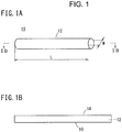
- an embolus material 10 has an elongated filling body 12.
- the filling body 12 is injected into a blood vessel of a living body via a catheter 90 (refer to Figs. 5A to 5C ), and a width W thereof is smaller than an inner diameter of the catheter 90 to be used in a state before the filling body is swollen (dried state) .
- the width W is, for example, about 0.2 mm to 2 mm.
- a length L of the filling body 12 is 0.5 cm to 100 cm in the dried state.
- the filling body 12 is formed in a long shape in which a ratio (L/W) of the length L to the width W is 2 or greater.
- a cross-sectional shape of the filling body 12 is not limited to the illustrated rectangular shape, and may be a shape such as a circular shape, an elliptical shape, or a polygonal shape.
- the filling body 12 may be formed in a tubular shape of which a central portion is hollow.
- the filling body 12 is made of a hydrogel that is expanded through contact with water in a biological fluid.
- the hydrogel is a polymer material that is swollen by absorbing water, and has polymer chains crosslinked in a three-dimensional mesh shape. In a dried state, the polymer chains are in an entangled state. When water molecules diffuse into the polymer chains, the polymer chains are loosened, and thus the mesh structure is dilated by containing the water molecules and is thus swollen.
- a polyacrylic acid, a polymethacrylic acid, a polyacrylamide, a polyhydroxyethyl methacrylate and derivatives thereof, a cross-linked polymer of a polyol such as a polyvinyl alcohol, a polyvinylpyrrolidone, or a polyethylene glycol, or a polysaccharide-based hydrogel may be used.
- the filling body 12 has a difference in swelling characteristics between a first side portion 14 extending in a longitudinal direction of the filling body 12 and a second side portion 16 extending in parallel thereto in a cross-sectional view of Fig. 1B .
- a swelling rate of the hydrogel is changed between the vicinity of the first side portion 14 and the vicinity of the second side portion 16.
- the first side portion 14 is provided with a plurality of slits with a predetermined depth, and is formed such that a surface area of the first side portion 14 is larger than a surface area of the second side portion 16.
- an infiltration rate of water from the first side portion 14 is higher than an infiltration rate of water from the second side portion 16.
- a swelling rate of the hydrogel increases as the infiltration rate of water increases.
- the first side portion 14 becomes transitionally longer than the second side portion 16 to cause curving.
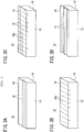
- the embolus material 10 is manufactured according to steps illustrated in Figs. 2A to 2C .
- a thin plate-shaped hydrogel 12a is formed.
- the hydrogel 12a may be produced, for example, by crosslinking ethylenically unsaturated monomers with radiation, heat, a redox agent, a nucleophile, or the like.
- a raw material solution for the hydrogel may contain an ethylenically unsaturated monomer, a crosslinking agent that forms a crosslinking structure, and a suitable solvent. The raw material solution is poured into a mold.
- ethylenically unsaturated monomer a 2-hydroxyethyl methacrylate, a hydroxybutyl acrylate, a t-butylacrylamide, an N,N'-methylenebisacrylamide, an N-vinylpyrrolidinone, an N-isopropylacrylamide, an acrylic acid, and an ethylenically unsaturated carboxylic acid having a hydroxyl group, a sulfuric acid group, a salt thereof, an amino group, and/or an ammonium group may be used.
- the crosslinking agent is a compound containing a branched molecule having at least two functional groups, and, for example, an ester, a carbonate, a thioester, a carbamate, an oxalate, a thioester, an N,N'-methylenebisacrylamide, and an ethylene glycol dimethacrylate may be used.
- the ethylenically unsaturated monomer in the raw material solution is polymerized by a stimulus such as ionizing radiation, ultraviolet light, or heat, to form a hydrogel, but the raw material solution may contain a polymerization initiator that generates a free radical to initiate a reaction as necessary.
- a polymerization initiator for example, azobisisobutyronitrile (AIBN) or derivatives thereof may be used.
- the raw material solution may contain a visualization agent for checking an indwelling position 94a of the embolus material 10 in a blood vessel 94 or for checking a state after the embolus material is indwelled.
- the visualization agent may be introduced according to a method in which solid particles containing an element such as barium sulfate, bismuth, tantalum, platinum, or gold through which radiation is hardly transmitted are dispersed in the hydrogel.
- the visualization agent may be introduced according to a method in which an organic compound containing an atom having a large atomic number such as chlorine, bromine, or iodine may be polymerized into a polymer.
- solvent for example, isopropyl alcohol, dichloromethane, acetone, water, ethanol, or a combination thereof may be used.
- the thin plate-shaped hydrogel 12a illustrated in Fig. 2A is formed by polymerizing the raw material solution according to a method of heating the raw material solution with a heating medium such as hot water (100°C) for several hours, or a method of irradiating the raw material solution with ionizing radiation or ultraviolet rays.
- a heating medium such as hot water (100°C) for several hours
- a method of irradiating the raw material solution with ionizing radiation or ultraviolet rays is formed by polymerizing the raw material solution according to a method of heating the raw material solution with a heating medium such as hot water (100°C) for several hours, or a method of irradiating the raw material solution with ionizing radiation or ultraviolet rays.
- slits 18 are formed on a surface of the thin plate-shaped hydrogel 12a.
- the slits 18 are formed by cutting a part of the surface side of the hydrogel 12a with a knife blade or laser light.
- slits 18a in a direction intersecting the longitudinal direction of the filling body 12 may be formed.
- lattice-shaped slits 18 and 18a as illustrated in Fig. 3C or groove-shaped slits 17 extending in the longitudinal direction of the filling body 12 as illustrated in Fig. 3D may be formed.
- the hydrogel 12a in which the slits 18 are formed are cleaned and dried, and is then cut into elongated thread-shaped shapes by a knife blade or a laser processing machine. Consequently, the embolus material 10 having the filling body 12 having an elongated and long shape is completed.
- the embolus material 10 may be formed by polymerizing the hydrogel in a tube having a predetermined cross-sectional shape.
- a description will be made of another method of manufacturing the embolus material 10 of the present embodiment.
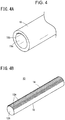
- a polymerization reaction of hydrogel is performed by using a tube 19 illustrated in Fig. 4A .
- the tube 19 has a plurality of projection portions 19b formed on a part of an inner circumferential portion 19a.
- the projection portions 19b extend in an axial direction of the tube 19, and are partially formed in a circumferential direction in a concentrated manner.
- a portion facing the projection portions 19b is a smooth inner circumferential portion 19a.
- HYTREL registered trademark
- the tube 19 can be dissolved in a predetermined solvent, and the filling body 12 can be easily taken out from the tube 19.
- a raw material solution for hydrogel is filled into the tube 19.
- a polymerization reaction crosslinking reaction
- the raw material solution is polymerized according to a method of heating the tube 19 with a heating medium such as hot water (100°C) for several hours, or a method of irradiating the tube 19 with ionizing radiation or ultraviolet rays.
- the tube 19 is dissolved in a predetermined solvent to be removed, and thus a filling body 12A illustrated in Fig. 4B is obtained.
- the filling body 12A has a plurality of grooves 18A in which the projection portions 19b of the tube 19 are reflected at one side portion (first side portion 14) of the tube 19 in the longitudinal direction.
- the first side portion 14 provided with the grooves 18A has a surface area larger than that of the other side portion (second side portion 16) formed of the smooth circumferential surface, and thus has a higher swelling rate.
- the embolus material 10 of the present embodiment is obtained by cleaning and drying the filling body 12.
- the embolus material 10 manufactured as described above operates as follows.
- the embolus material 10 in a dried state is inserted into the catheter 90.
- the catheter 90 is inserted into, for example, the blood vessel 94 as a biological lumen.
- a distal end of the catheter 90 advances through the blood vessel 94 of a patient until reaching the indwelling position 94a in the blood vessel 94.
- the embolus material 10 is pushed out by a pusher 92.
- the pushed-out embolus material 10 starts to be swollen due to contact with blood.
- the embolus material 10 pushed into the blood vessel 94 is curved to form an annular or coil-shaped (spiral) three-dimensional structure. Since the three-dimensional structure is larger than an inner diameter of the blood vessel 94, the embolus material 10 is not pushed by a flow of the biological fluid and is clogged in the indwelling position 94a in the blood vessel 94.
- the embolus material 10 is not limited to the illustrated example, and a plurality of embolus materials are indwelled as necessary.
- the embolus material 10 indwelled at the indwelling position 94a is swollen to be filled into the blood vessel 94 at the indwelling position 94a without a gap, and thus embolization is completed.
- the coil-shaped (spiral) curving of the embolus material 10 as illustrated is not essential to prevent movement in a biological lumen (blood vessel).
- the embolus material 10 is not necessarily required to be curved in a coil shape (spiral shape), and comes into contact with an inner wall of the blood vessel 94 in a curved state, and just comes into contact with the inner wall of the blood vessel 94 while exhibiting stress due to deformation, and thus exhibits resistance to the flow of the biological fluid.
- the embolus material 10 can embolize the inside of the blood vessel 94 without moving due to the flow of the biological fluid.
- the embolus material 10 may use not also for embolizing the blood vessel 94 but also for treating an aortic aneurysm 96.
- the aortic aneurysm 96 is treated according to stent graft treatment that is less invasive and less burdensome on patients.
- the stent graft treatment is treatment of inhibiting blood from flowing into the aortic aneurysm 96 by providing an artificial blood vessel (stent graft 102) in the aortic aneurysm 96.
- Type 2 endoleak is a complication in which a blood flow that was flowing out in a forward direction from the aortic aneurysm 96 to a terminal blood vessel (bifurcated blood vessel 98) is reversed from the bifurcated blood vessel 98 side to the aortic aneurysm 96 due to the provision of the stent graft 102, and thus blood remains in the aortic aneurysm 96. If this is left unattended for a long period of time, the aortic aneurysm 96 may be enlarged by the reversed blood.
- Type 2 endoleak is said to occur in about 20% to 30% of patients who have undergone stent graft treatment in the long term.
- Type 2 endoleaks can be treated by indwelling the embolus material 10 of the present embodiment in the aortic aneurysm 96 and thus embolizing the aortic aneurysm 96.
- the catheter 100 is inserted into the aortic aneurysm 96 through the bifurcated blood vessel 98 connected to the aortic aneurysm 96 or from between the stent graft 102 and the iliac artery 97 (or the aorta 95), and the embolus material 10 is indwelled in the aortic aneurysm 96 via the catheter 100.
- the embolus material 10 is swollen in the aortic aneurysm 96 to embolize the aortic aneurysm 96, and thus inhibits blood from inflowing into the aortic aneurysm 96.
- the filling body 12 is curved due to a swelling characteristic difference to form a coil-shaped structure, and is enlarged to be larger than a diameter of the bifurcated blood vessel 98 connected to the aortic aneurysm 96.
- the embolus material 10 does not enter the bifurcated blood vessel 98 unlike a liquid embolus material or a bead-like embolus material of the related art. Therefore, the embolus material 10 can safely embolize the aortic aneurysm 96 without causing a complication due to distal embolization via the bifurcated blood vessel 98.
- the embolus material 10 of the present embodiment is suitable for treating Type 2 endoleaks.
- the embolus material 10 of the present embodiment since the elongated filling body 12 is curved due to a difference in swelling characteristics, a curved portion is caught at a biological lumen, and thus it is possible to prevent movement of the embolus material due to a flow of a biological fluid. As a result, the embolus material stays to be swollen at a desired position and can thus inhibit a blood flow.
- an embolus material 20 is formed of a porous filling body 22.
- a porous density (density of pores) of the filling body 22 the porous density of the first side portion 14 is higher than the porous density of the second side portion 16. Consequently, a surface area of the first side portion 14 is larger than a surface area of the second side portion 16, and thus a swelling rate of the first side portion 14 is also higher.
- the filling body 22 is manufactured as follows.
- a raw material solution 22a for the filling body 22 is prepared, and is poured into a mold.
- the raw material solution 22a of the present embodiment contains a pore forming agent 24 in addition to an ethylenically unsaturated monomer, a crosslinking agent, a polymerization initiator, and a solvent.
- a pore forming agent 24 in addition to an ethylenically unsaturated monomer, a crosslinking agent, a polymerization initiator, and a solvent.
- the ethylenically unsaturated monomer, the crosslinking agent, the polymerization initiator, and the solvent the same materials as those in the first embodiment may be used.
- the pore forming agent 24 is made of a supersaturated soluble substance that cannot be completely dissolved in the raw material solution 22a, or a substance that is insoluble in the raw material solution 22a and soluble in a cleaning liquid.
- the raw material solution 22a may be appropriately mixed with an organic solvent to reduce the polarity of the solvent and thus to prevent the pore forming agent 24 from being dissolved.
- the pore forming agent 24 specifically, for example, sodium chloride, potassium chloride, ice, sucrose, and sodium bicarbonate may be used.
- the pore forming agent 24 it is preferable to use a substance that has a larger relative density than that of the raw material solution 22a and precipitates in the raw material solution 22a, or a substance that has a smaller relative density than that of the raw material solution 22a and floats in the raw material solution 22a.
- the pore forming agent 24 is dispersed as particles having a diameter of, for example, 500 ⁇ m or less in the raw material solution 22a.
- the raw material solution 22a containing the pore forming agent 24 is stirred and uniformly suspended, and is then poured into a mold.
- a thin plate-shaped hydrogel may be formed, and a tube may be formed.
- a tube having a predetermined diameter produced from HYTREL (registered trademark) manufactured by DuPont may be used. Such a tube can be dissolved in a predetermined solvent, and the filling body 22 can be easily taken out from the tube.
- the raw material solution 22a is placed still for a predetermined time. Consequently, the particles of the pore forming agent 24 having a larger relative density than that of the raw material solution 22a precipitate, and the particles of the pore forming agent 24 gather near a bottom part of the mold.
- the raw material solution 22a in which the pore forming agent 24 has precipitated is heated to start a polymerization reaction and to form hydrogel 22b. Consequently, a position of the pore forming agent 24 is fixed, and the hydrogel 22b containing a lot of the pore forming agent 24 at the bottom part is formed.
- the pore forming agent 24 may be unevenly distributed by an electric field by using particles having electric charge for the pore forming agent 24.
- the pore forming agent 24 may be unevenly distributed by an electric field by using particles having electric charge for the pore forming agent 24.
- negatively charged particles composed of a polysaccharide such as an alginic acid and agarose may be used.
- positively charged particles composed of gelatin may be used.
- the thread-shaped hydrogel 22b is taken out by dissolving and removing the tube.
- the hydrogel 22b is cleaned with a cleaning liquid that can dissolve the pore forming agent 24. Consequently, the pore forming agent 24 is dissolved in the cleaning liquid and is thus removed from the hydrogel 22b. Since the pore forming agent 24 is dissolved and removed in the above-described way, pores 26 having shapes of the particles of the pore forming agent 24 are formed, and the porous hydrogel 22b is obtained.
- the pores 26 concentrate at a bottom part (first side portion 14) of the hydrogel 22b, and are slightly present near a top part (second side portion 16) thereof. In other words, the size of the porous density is biased.
- the filling body 22 having a high porous density on the first side portion 14 and a low porous density on the second side portion 16 is obtained.
- the hydrogel in Fig. 7C may be cleaned and dried, and then cut into thin pieces to be formed into a thread-shaped shape.
- the embolus material 20 of the present embodiment may also be formed according to a method in which a hydrogel containing the pore forming agent 24 is stuck to a hydrogel not containing the pore forming agent 24 (refer to Fig. 12 ), or a method in which the hydrogel containing the pore forming agent 24 and the hydrogel not containing the pore forming agent 24 are polymerized to be stacked (refer to Figs. 13A to 13C ).
- the embolus material 20 of the present embodiment includes the filling body 22 having a high porous density at the first side portion 14 and a low porous density at the second side portion 16.
- the first side portion 14 has a large surface area due to a large number of pores 26, and thus has a higher water infiltration rate than that of the second side portion 16.
- a swelling rate of the first side portion 14 is higher than a swelling rate of the second side portion 16, and can thus cause curving in the swelling process. Therefore, the embolus material 20 can also achieve the same effect as that achieved by the embolus material 10 of the first embodiment.
- the embolus material 20 of the present embodiment is not limited the above description.
- an embolus material may be used in which the pore forming agent 24 is not removed from the hydrogel 22b containing the pore forming agent 24.
- the pore forming agent 24 is cleaned while being careful not to leach the pore forming agent, and is then dried, and thus the embolus material is obtained.
- a supersaturated solution containing the components of the pore forming agent 24 may be used as a cleaning liquid.
- the hydrogel 22b may be cleaned with a cleaning liquid in which the pore forming agent 24 is less likely to be leached by mixing an organic solvent to reduce the polarity.
- the pore forming agent 24 is dissolved and removed through contact with a biological fluid such as blood, and, thus, as illustrated in Fig. 7C , the embolus material 20 having a high porous density at the first side portion 14 is formed in a living body.
- the first side portion 14 is swollen relatively fast, and can thus cause curving.
- the pore forming agent 24 for example, particles of sugar such as glucose or sucrose, or particles of an electrolyte salt such as salt may be used. It is preferable to use a low molecular weight substance as the pore forming agent 24 that is eluted into a living body.
- the low molecular weight substance can be diffused through the inside of the mesh structure of the hydrogel 22b forming the embolus material, and can thus be quickly leached.
- an electrolyte is used as the pore forming agent 24, an ionic strength of the hydrogel 22b around the electrolyte is increased, and a swelling rate is further increased, which is preferable.
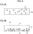
- an embolus material 30 has a structure in which insoluble particles 33 are unevenly distributed near the second side portion 16 of a filling body 32.
- infiltration of water is hindered since the insoluble particles 33 are present at the second side portion 16.
- a swelling rate of the second side portion 16 is lower than a swelling rate of the first side portion 14, and thus the embolus material 30 is curved when coming into contact with water.
- the embolus material 30 of the present embodiment is curved by providing the structure of hindering infiltration of water at the second side portion 16.
- the insoluble particles 33 are dispersed in a raw material solution 32a for a hydrogel.
- the insoluble particles 33 for example, particles of barium sulfate, bismuth, tantalum, platinum, gold, silica, or polystyrene may be used.
- the raw material solution 32a in which the insoluble particles 33 are dispersed is injected into a mold such as a tube, and the tube is horizontally disposed and is placed still for a predetermined time. Consequently, as illustrated in Fig. 8B , the insoluble particles 33 float or precipitate due to the difference in relative density between the raw material solution 32a and the insoluble particles 33, and the insoluble particles 33 are unevenly distributed on a side portion (an upper side or a lower side) of the horizontally disposed mold.
- the insoluble particles 33 may be unevenly distributed by applying an electric field.
- the insoluble particles 33 may be particles having a surface potential.
- silica particles and polystyrene particles have a surface potential, and the insoluble particles 33 can be unevenly distributed by an electric field.
- the raw material solution 32a is heated to be polymerized, and thus forms the filling body 32 in which the insoluble particles 33 are unevenly distributed at the second side portion 16.
- the mold for example, a tube
- the filling body 32 is taken out, cleaned, and dried to obtain the embolus material 30 of the present embodiment.
- the embolus material 30 of the present embodiment may also be formed according to a method in which a hydrogel not containing the insoluble particles 33 is stuck to a hydrogel containing the insoluble particles 33 (refer to Fig. 12 ), or a method in which the hydrogel not containing the insoluble particles 33 and the hydrogel containing the insoluble particles 33 are polymerized to be stacked (refer to Figs. 13A to 13C ).
- the insoluble particles 33 are unevenly distributed at the second side portion 16 of the filling body 32 made of a hydrogel.
- water is less likely to infiltrate, so that a swelling rate is low.
- a swelling rate of the second side portion 16 of the filling body 32 is relatively low compared with a swelling rate of the first side portion 14, and thus the embolus material 30 can be curved when being swollen. Consequently, the embolus material 30 can prevent outflow thereof due to a biological fluid in a biological lumen.
- a thread-shaped structure extending in the longitudinal direction of the embolus material 30 may be added to a raw material solution for a hydrogel.
- a structure having a lower expansion swelling ratio (equilibrium swelling degree) than that of a hydrogel may be used as the thread-shaped structure.
- the thread-shaped structure precipitates in a raw material solution to be unevenly distributed at the second side portion 16.
- the embolus material 30 including the thread-shaped structure can be curved since a swelling ratio of the second side portion 16 is lower than that of the first side portion 14.
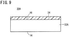
- an embolus material 30A includes a filling body 32A and a waterproof film 34.
- the filling body 32A may be made of a uniform hydrogel that includes a first side portion 14 that is a side extending in a longitudinal direction and a second side portion 16 extending in parallel thereto.
- the second side portion 16 of the filling body 32A is covered with the waterproof film 34.
- the waterproof film 34 may be made of a material inhibiting infiltration of water or a material of which a water infiltration rate is lower than that of the hydrogel forming the filling body 32.
- a material for example, a film of cellulose or polylactic acid may be used.
- the waterproof film 34 is formed by applying or adhering a material forming the waterproof film 34 to the hydrogel forming the filling body 32A.
- the hydrogel covered with the waterproof film 34 is cut into thread-shaped shapes, and thus the elongated filling body 32A that is elongated is obtained.
- the filling body 32A may be directly formed into a thread-shaped shape by polymerizing the hydrogel in a tube.
- the embolus material 30A of the present embodiment may be obtained by selectively applying the waterproof film 34 only to the second side portion 16 of the thread-shaped filling body 32A.
- the second side portion 16 is covered with the waterproof film 34, and thus the infiltration of water from the second side portion 16 into the filling body 32A is inhibited.
- a swelling rate of the first side portion 14 is higher than a swelling rate of the second side portion 16, and thus the filling body 32 can be curved in the swelling process. Therefore, the embolus material 30A can also achieve the same effect as that achieved by the embolus material 10 of the first embodiment.
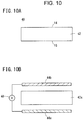
- an embolus material 40 includes a filling body 42 in which ionic strengths of a hydrogel are different from each other between the first side portion 14 and the second side portion 16.
- a polymer forming the hydrogel forming the filling body 42 contains a basic substituent such as a hydroxyl group or an amine group, or an acidic substituent such as a carboxyl group or a sulfate group.
- the polymer having such a basic substituent or an acidic substituent is also called a polyelectrolyte and is bonded to various cations or anions.
- a concentration (ionic strength) of an ion-active group bonded to the cations or the anions is high at the first side portion 14 in the filling body 42, and is inclined such that the ionic strength gradually decreases toward the second side portion 16.
- a hydrogel containing a large amount of basic substituents or acidic substituents and having a higher ionic strength has a higher affinity for water, a faster water infiltration rate, and a faster swelling rate.
- the swelling rate of the first side portion 14 having a high ionic strength is higher than a swelling rate of the second side portion 16.
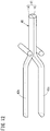
- the filling body 42 is subjected to a polymerization reaction while applying an electric field to a raw material solution 42a for the hydrogel forming the filling body 42.
- a tube filled with the raw material solution 42a is disposed between a pair of electrodes 44a and 44b, and the polymerization reaction is performed while applying a voltage between the electrodes 44a and 44b and heating the tube with a heat medium such as boiling water.
- the raw material solution 42a contains only ion-active groups (substituents) bonded to either cations or anions.
- the hydrogel is taken out from the tube, and thus the thread-shaped filling body 42 is obtained.
- the filling body 42 is cleaned and dried as appropriate, and thus the embolus material 40 of the present embodiment is obtained.
- the hydrogel may be polymerized in a plate-shaped mold instead of using the tube.
- the plate-shaped hydrogel obtained through the polymerization reaction is cut into thin thread-shaped shapes to obtain the elongated and long shaped filling body 42.
- the embolus material 40 (refer to Fig. 10A ) has a gradient of ionic strength depending on the concentration of an electrolyte with which the filling body 42 is impregnated, instead of the hydrogel itself forming the filling body 42. Also in Modification Example 1, a concentration (ionic strength) of the electrolyte in the filling body 42 is high at the first side portion 14, and a concentration (ionic strength) of the electrolyte is low at the second side portion 16.
- the electrolyte with which the filling body 42 is impregnated for example, a salt of ions of sodium, potassium, calcium, or magnesium, and a chlorine, an acetic acid, a citric acid, or a phosphoric acid may be used.
- a polyelectrolyte having an acidic substituent or a basic substituent may be used as the electrolyte.
- the embolus material 40 of the present modification example there is a difference in osmotic pressure between the first side portion 14 having a high electrolyte concentration and the second side portion 16 having a low electrolyte concentration, and the first side portion 14 having a high electrolyte concentration attracts more water.
- a swelling rate of the first side portion 14 having a high electrolyte concentration is higher than a swelling rate of the second side portion 16, and thus the embolus material can be curved when being swollen.
- the embolus material 40 of the present embodiment may be manufactured by forming a hydrogel having a uniform ionic strength and contacting a solution containing a monomer or a polymer having an ion-active group with one side (first side portion 14) of the hydrogel. as illustrated in Fig. 11A , a raw material solution for the hydrogel is filled into a tube 45, and the tube 45 is heated for a predetermined time to polymerize the raw material solution and thus to form the filling body 42 made of the thread-shaped hydrogel.
- a mask 46 in which an opening portion 46a is formed in a portion corresponding to the first side portion 14 is formed on an outer peripheral surface of the filling body 42.
- an electrolyte is infiltrated into the first side portion 14 of the filling body 42 by bringing a solution containing an electrolyte into contact with the first side portion 14 of the filling body 42 exposed to the opening portion 46a of the mask 46. Consequently, the filling body 42 having a gradient in ionic strength between the first side portion 14 and the second side portion 16 is obtained.
- the electrolyte is a polyelectrolyte
- the infiltrated polyelectrolyte may be polymerized with the hydrogel forming the filling body 42 through reheating as necessary.
- the embolus material 40 is manufactured by chemically or physically joining a plurality of hydrogels having different ionic strengths.
- a first hydrogel 42b having a relatively high ionic strength and a second hydrogel 42c having a relatively low ionic strength are produced.
- each of the first hydrogel 42b and the second hydrogel 42c is formed as a long body having a semicircular section.
- the first and second hydrogels 42b and 42c may be produced by polymerizing a raw material solution having a predetermined composition to an appropriate hardness and then extruding the raw material solution.
- the first hydrogel 42b and the second hydrogel 42c are stuck to each other and are heated as appropriate, and the first hydrogel 42b and the second hydrogel 42c are joined through a polymerization reaction, to form the filling body 42.
- the filling body 42 is cleaned and dried, and thus the embolus material 40 of the present embodiment is completed.
- a portion made of the first hydrogel 42b having a high ionic strength serves as the first side portion 14
- a portion made of the second hydrogel 42c having a low ionic strength serves as the second side portion 16.
- first hydrogel 42b and the second hydrogel 42c may be formed in a thin plate shape and may be joined to each other to be then cut into thin thread-shaped shapes such that the filling body 42 is formed.
- the filling body 42 is formed by stacking hydrogels having different ionic strengths in layers by causing a polymerization reaction while sequentially pouring raw material solutions having different ionic strengths into a heated mold.
- the ionic strengths of the raw material solutions may be gradually increased or decreased to provide a gradient of ionic strength in the stacked hydrogel layers.
- the hydrogels formed in above-described way are cut into thread-shaped shapes, and thus it is possible to obtain the filling body 42 having a gradient of ionic strength between the first side portion 14 and the second side portion 16.
- Modification Example 3 may be applied to a manufacturing method using a tube. As illustrated in Fig. 13A , the tube 45 is prepared, and about a half amount of a raw material solution 42c1 is injected into the tube 45. Next, the second hydrogel 42c is formed by horizontally disposing the tube 45 in the entire length direction and polymerizing the raw material solution 42c1 in the tube 45.
- a raw material solution 42b1 is injected into a remaining space in the tube 45 in which the second hydrogel 42c is formed.
- the raw material solution 42b1 contains a larger amount of electrolyte than that of the second hydrogel 42c and thus has a high ionic strength.
- the raw material solution 42b1 is polymerized.
- the filling body 42 in which the first hydrogel 42b is stacked on the second hydrogel 42c.
- the filling body 42 is taken out by dissolving and removing the tube 45 with a predetermined solvent, and the embolus material 40 of the present embodiment can be obtained by cleaning and drying the filling body 42.
- a gradient of ionic strength may be provided according to a method in which the filling body 42 is made of a hydrogel having a polymer chain having an acidic ion-active group, and the second side portion 16 thereof is brought into contact with a low-ph solution to reduce an ionic strength near the second side portion 16.
- a gradient of ionic strength may be provided according to a method in which the filling body 42 is made of a hydrogel having a polymer chain having a basic ion-active group, and the second side portion 16 thereof is brought into contact with a high-ph solution to reduce an ionic strength near the second side portion 16.
- Modification Example 4 may be performed by using a tube.
- the mask 46 illustrated in Fig. 11B may be used.
- the mask 46 in which the opening portion 46a is provided in the second side portion 16 is formed on the outer peripheral portion of the filling body 42.
- a low-ph or high-ph solution may be brought into contact with the second side portion 16 exposed to the opening portion 46a to reduce an ionic strength such that the embolus material 40 of the present embodiment is formed.
- an ionic strength of the filling body 42 differs depending on a location.
- a swelling rate of the first side portion 14 having a higher ionic strength is higher than a swelling rate of the second side portion 16. Consequently, curving can be caused in the swelling process of the embolus material 40. Therefore, the embolus material 40 can also achieve the same effect as that achieved by the embolus material 10 of the first embodiment.
- an embolus material 50 is provided with a region 52a having high hydrophilicity and a region 52b having low hydrophilicity inside a filling body 52.
- the region 52a having high hydrophilicity contains a large number of molecules having a hydrophilic functional group in a polymer chain forming a hydrogel.
- the region 52b having low hydrophilicity contains a large number of hydrophobic molecules in a polymer chain forming the hydrogel.
- the hydrophilic functional group include a hydroxyl group, a sulfuric acid group, an amino group, and a carboxyl group.
- the hydrophobic functional group include a methyl group and a benzene group.
- the embolus material 50 is manufactured by performing a polymerization reaction in a container 54 interposed between a hydrophilic basal lamella 58 and a hydrophobic (or lipophilic) basal lamella 56 when a hydrogel forming the filling body 52 is polymerized.
- a hydrophilic basal lamella 58 a basal lamella made of polyacrylamide, polyester, or the like may be used.
- a hydrophobic basal lamella for example, a basal lamella made of polyethylene or polystyrene may be used.
- a solution which contains a hydrophilic polymer (for example, a polymer, a polysaccharide, or a polyol having electric charge) or a hydrophilic monomer (for example, acrylamide, a sugar, or a hydrophilic amino acid), and a hydrophobic polymer (for example, a hydrophobic polyamino acid or polyester) or a hydrophobic monomer (for example, a hydrophobic amino acid).
- a hydrophilic polymer for example, a polymer, a polysaccharide, or a polyol having electric charge
- a hydrophilic monomer for example, acrylamide, a sugar, or a hydrophilic amino acid
- a hydrophobic polymer for example, a hydrophobic polyamino acid or polyester
- a hydrophobic monomer for example, a hydrophobic amino acid
- the hydrophilic polymer or monomer gathers on the hydrophilic basal lamella 58 side, and the hydrophobic polymer or monomer gathers on the hydrophobic basal lamella 56 side.
- the raw material solution 53 is heated to be polymerized, and thus the hydrophilic region 52a and the hydrophobic region 52b are formed in the hydrogel.
- the hydrogel produced in the above-described way is dried and cut into pieces, and thus it is possible to obtain the filling body 52 in which the hydrophilic region 52a is formed at the first side portion 14 and the hydrophobic region 52b is formed at the second side portion 16.
- the embolus material 50 of the present embodiment may also be formed according to a method in which a hydrophilic hydrogel is stuck to a hydrophobic hydrogel (refer to Fig. 12 ), or a method in which the hydrophilic hydrogel and the hydrophobic hydrogel are polymerized to be stacked (refer to Figs. 13A to 13C ).
- the embolus material 50 manufactured as described above an infiltration rate of water is higher in the hydrophilic region 52a than in the hydrophobic region 52b.
- the first side portion 14 at which the hydrophilic region 52a is formed is swollen faster than the second side portion 16, and thus curving can be caused in the swelling process. Therefore, the embolus material 50 can also achieve the same effect as that achieved by the embolus material 10 of the first embodiment.
- the first side portion 14 that contains a large number of hydrophilic molecules also incorporates more water molecules in a polymer chain, and thus the equilibrium swelling degree also increases.
- the first side portion 14 is also higher than the second side portion 16 in terms of equilibrium swelling degree. Therefore, the embolus material 50 can be maintained to be curved even in a case of being completely swollen.
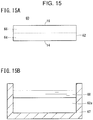
- an embolus material 60 includes a filling body 62 having a gradient of crosslinking density.
- the filling body 62 has a first region 64 having a low crosslinking density and a second region 66 having a high crosslinking density.
- the first side portion 14 is formed on the first region 64 side
- the second side portion 16 is formed on the second region 66 side.
- a mesh structure of polymer chains forming a hydrogel is fine, and thus it is difficult for water to be incorporated into the mesh structure such that swelling is difficult.
- the mesh structure of the polymer chains is larger than in the second region 66, and swelling easily occurs.
- a swelling rate is higher in the first region 64 having a low crosslinking density and is lower in the second region 66 having a high crosslinking density.
- a swelling rate and an equilibrium swelling degree of the first side portion 14 are higher than a swelling rate and an equilibrium swelling degree of the second side portion 16.
- the embolus material 60 is manufactured according to a method illustrated in Fig. 15B .
- a raw material solution is polymerized in a mold 67 to form a uniform hydrogel 62a.
- a solution 68 containing a crosslinking agent is brought into contact with one surface (an upper surface in the figure) of the hydrogel 62a. Consequently, the crosslinking agent is infiltrated from the upper surface side of the hydrogel 62a.
- a concentration distribution occurs in the hydrogel 62a such that the concentration of the crosslinking agent becomes higher toward the upper surface.
- the hydrogel 62a containing the crosslinking agent is heated, and thus the crosslinking agent is polymerized.
- the hydrogel 62a Since a larger amount of polymers is crosslinked as a larger amount of the crosslinking agent is contained, a gradient of crosslinking density can be generated near the upper surface of the hydrogel 62a and near the bottom surface thereof. Next, the hydrogel 62a is cut into thread-shaped shapes and is dried, and thus the embolus material 60 is obtained.
- a tube may be used to manufacture the embolus material 60 of the present embodiment.
- the tube 45 illustrated in Fig. 11A is used, and the uniform thread-shaped hydrogel 62a is formed in the tube 45.
- a side portion of the tube 45 is notched to form the mask 46 having the opening portion 46a.
- a crosslinking agent is infiltrated into the hydrogel 62a exposed to the opening portion 46a, and then the hydrogel 62a is reheated to polymerize the crosslinking agent.
- the hydrogel 62a is cleaned and dried, and thus the embolus material 60 is obtained.
- the embolus material 60 of the present embodiment may also be formed according to a method in which the hydrogels 62a having different crosslinking densities are stuck to each other (refer to Fig. 12 ), or a method in which raw material solutions containing different components are polymerized to be sequentially stacked (refer to Figs. 13A to 13C ).
- the filling body 62 is obtained such that a swelling rate of the first side portion 14 is higher than a swelling rate of the second side portion 16, and thus curving can be caused in the swelling process. Consequently, it is possible to achieve the same effect as the effect achieved by the embolus material 10 of the first embodiment. Since an equilibrium swelling degree of the first side portion 14 is higher than an equilibrium swelling degree of the second side portion 16, the embolus material 60 can be maintained to be curved even after being swollen. Therefore, movement due to a flow of a biological fluid more hardly occurs, which is preferable.
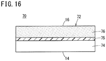
- an embolus material 70 includes a filling body 72 in which a polymer concentration differs.
- a low concentration region 74 and a high concentration region 76 are formed in the filling body 72.
- the first side portion 14 is formed on the low concentration region 74 side, and the second side portion 16 is formed on the high concentration region 76 side.
- the concentration of a polymer forming a skeleton of a hydrogel is relatively low in the low concentration region 74, and the concentration of the polymer forming the skeleton of the hydrogel is relatively high in the high concentration region 76.
- a swelling rate of the first side portion 14 near the low concentration region 74 of the filling body 72 is higher than a swelling rate of the second side portion 16 near the high concentration region 76.
- the low concentration region 74 (first hydrogel layer) and the high concentration region 76 (second hydrogel layer) may be formed differently by adjusting a ratio between a solvent and a monomer in a raw material solution for a hydrogel forming the filling body 72. That is, the hydrogel layer forming the high concentration region 76 is formed by polymerizing the raw material solution containing a small amount of the solvent and a high concentration of the monomer. The hydrogel layer forming the low concentration region 74 is formed by pouring a raw material solution containing a low concentration of the monomer and polymerizing the raw material solution. Thereafter, the first hydrogel layer and the second hydrogel layer are adhered to each other via an adhesive layer 75, a hydrogel in which the high concentration region 76 and the low concentration region 74 are stacked is obtained.
- the hydrogel in which the high concentration region 76 and the low concentration region 74 are stacked is cut into thread-shaped shapes and is dried, and thus manufacturing of the embolus material 70 of the present embodiment is completed.
- the embolus material 70 of the present embodiment may also be formed according to a method in which a hydrogel having a low polymer concentration is stuck to a hydrogel having a high polymer concentration (refer to Fig. 12 ), or a method in which the hydrogel having a low polymer concentration and the hydrogel having a high polymer concentration are polymerized to be stacked (refer to Figs. 13A to 13C ).
- a swelling rate of the first side portion 14 of the filling body 72 is higher than a swelling rate of the second side portion 16, and thus curving can be caused in the swelling process. Consequently, the embolus material 70 can also achieve the same effect as the effect achieved by the embolus material 10 of the first embodiment.
- a larger amount of water can be incorporated into the region having a high polymer density, and thus an equilibrium swelling degree increases. Therefore, when the embolus material 70 is brought into contact with water, the first side portion 14 first extends more quickly than the second side portion 16 and causes curving, but, in the end, a swelling ratio of the second side portion 16 is higher than that of the first side portion 14.
- the second side portion 16 extends longer such that the embolus material 70 is maintained in a curved state.
- embolus material and the method of manufacturing the same according to the present invention are not limited to the embodiments, and may employ various configurations without departing from the spirit of the present invention.
- embolus material that is indwelled in a biological lumen to inhibit a flow of a biological fluid, the embolus material including:
- the embolus material according to Appendix 1 in which the difference in swelling characteristics is a difference in swelling rate.
- the embolus material according to Appendix 1 in which the difference in swelling characteristics is a difference in equilibrium swelling degree.
- the embolus material according to Appendix 2 in which a pore forming agent that is leached to form a porous structure by coming into contact with the biological fluid is contained on a first side portion side of the filling body.
- embolus material in which the second side portion side of the filling body includes insoluble particles that are not dissolved in the biological fluid.
- embolus material according to any one of Appendixes 1 to 14, in which the filling body is indwelled in a aneurysm part of a blood vessel via a catheter.
- a method of manufacturing an embolus material that is indwelled in a biological lumen to inhibit a flow of a biological fluid including:
- a method of manufacturing an embolus material that is indwelled in a biological lumen to inhibit a flow of a biological fluid including:
- a method of manufacturing an embolus material that is indwelled in a biological lumen to inhibit a flow of a biological fluid including:
- a method of manufacturing an embolus material that is indwelled in a biological lumen to inhibit a flow of a biological fluid including:
- a method of manufacturing an embolus material that is indwelled in a biological lumen to inhibit a flow of a biological fluid including:
- An embolus method of indwelling an embolus material in a biological lumen to inhibit a flow of a biological fluid including an elongated filling body made of a material that is swollen when being brought into contact with the biological fluid, the filling body having a first side portion and a second side portion in a radial direction of the filling body, and the first side portion and the second side portion having different swelling characteristics.
Applications Claiming Priority (2)
| Application Number | Priority Date | Filing Date | Title |
|---|---|---|---|
| JP2018063998 | 2018-03-29 | ||
| PCT/JP2019/011706 WO2019188663A1 (fr) | 2018-03-29 | 2019-03-20 | Matériau embolique et son procédé de fabrication |
Publications (2)
| Publication Number | Publication Date |
|---|---|
| EP3766436A1 true EP3766436A1 (fr) | 2021-01-20 |
| EP3766436A4 EP3766436A4 (fr) | 2021-03-31 |
Family
ID=68059911
Family Applications (1)
| Application Number | Title | Priority Date | Filing Date |
|---|---|---|---|
| EP19775299.1A Pending EP3766436A4 (fr) | 2018-03-29 | 2019-03-20 | Matériau embolique et son procédé de fabrication |
Country Status (4)
| Country | Link |
|---|---|
| US (1) | US11559312B2 (fr) |
| EP (1) | EP3766436A4 (fr) |
| JP (1) | JP7248654B2 (fr) |
| WO (1) | WO2019188663A1 (fr) |
Families Citing this family (4)
| Publication number | Priority date | Publication date | Assignee | Title |
|---|---|---|---|---|
| WO2020226157A1 (fr) * | 2019-05-09 | 2020-11-12 | 国立大学法人横浜国立大学 | Hydrogel de pva et procédé pour la fabrication de celui-ci |
| CN113873963A (zh) | 2019-05-30 | 2021-12-31 | Devicor医疗产业收购公司 | 用于有限迁移的活检部位标记物 |
| WO2022209620A1 (fr) * | 2021-03-31 | 2022-10-06 | テルモ株式会社 | Matériau d'embole et procédé de production de matériau d'embole |
| WO2023037677A1 (fr) * | 2021-09-07 | 2023-03-16 | テルモ株式会社 | Spirale embolique |
Family Cites Families (22)
| Publication number | Priority date | Publication date | Assignee | Title |
|---|---|---|---|---|
| US4890612A (en) * | 1987-02-17 | 1990-01-02 | Kensey Nash Corporation | Device for sealing percutaneous puncture in a vessel |
| US7790192B2 (en) * | 1998-08-14 | 2010-09-07 | Accessclosure, Inc. | Apparatus and methods for sealing a vascular puncture |
| US6303100B1 (en) | 1999-03-19 | 2001-10-16 | Micro Therapeutics, Inc. | Methods for inhibiting the formation of potential endoleaks associated with endovascular repair of abdominal aortic aneurysms |
| US20030014075A1 (en) | 2001-07-16 | 2003-01-16 | Microvention, Inc. | Methods, materials and apparatus for deterring or preventing endoleaks following endovascular graft implanation |
| US8465516B2 (en) * | 2001-07-26 | 2013-06-18 | Oregon Health Science University | Bodily lumen closure apparatus and method |
| US7131997B2 (en) * | 2002-03-29 | 2006-11-07 | Scimed Life Systems, Inc. | Tissue treatment |
| JP2008523870A (ja) | 2004-12-20 | 2008-07-10 | カーブグラフト アーベー | キトサン組成物 |
| US20060178696A1 (en) | 2005-02-04 | 2006-08-10 | Porter Stephen C | Macroporous materials for use in aneurysms |
| US8585753B2 (en) * | 2006-03-04 | 2013-11-19 | John James Scanlon | Fibrillated biodegradable prosthesis |
| AU2007260653B2 (en) | 2006-06-15 | 2013-01-24 | Microvention, Inc. | Embolization device constructed from expansible polymer |
| US9492596B2 (en) * | 2006-11-06 | 2016-11-15 | Atrium Medical Corporation | Barrier layer with underlying medical device and one or more reinforcing support structures |
| KR101567111B1 (ko) | 2007-12-21 | 2015-11-06 | 마이크로벤션, 인코포레이티드 | 생의학 용도를 위한 히드로겔 필라멘트 |
| CN101938943B (zh) | 2008-03-31 | 2012-12-26 | 泰尔茂株式会社 | 医疗用闭塞装置 |
| JP2010162063A (ja) * | 2009-01-13 | 2010-07-29 | Japan Health Science Foundation | 塞栓材 |
| US8292918B2 (en) * | 2009-02-20 | 2012-10-23 | Boston Scientific Scimed, Inc. | Composite plug for arteriotomy closure and method of use |
| CA2760704C (fr) * | 2009-05-04 | 2017-10-03 | Incept, Llc | Biomateriaux pour la fermeture de voie et de ponction |
| CA2774646A1 (fr) | 2009-09-24 | 2011-03-31 | Microvention, Inc. | Filaments d'hydrogel injectable pour des utilisations biomedicales |
| US8858592B2 (en) * | 2009-11-24 | 2014-10-14 | Covidien Lp | Wound plugs |
| US20120101519A1 (en) | 2010-10-25 | 2012-04-26 | Boston Scientific Scimed, Inc. | Porous vascular closure plug with starch powder |
| US10327781B2 (en) | 2012-11-13 | 2019-06-25 | Covidien Lp | Occlusive devices |
| KR20220144883A (ko) | 2014-05-29 | 2022-10-27 | 액세스클로저, 아이엔씨. | 키토산 및 폴리에틸렌 글리콜 공중합체 및 이를 사용하여 혈관 천공을 밀봉하기 위한 방법 및 디바이스 |
| JP6527244B2 (ja) * | 2015-03-26 | 2019-06-05 | ボストン サイエンティフィック サイムド,インコーポレイテッドBoston Scientific Scimed,Inc. | 生体基礎を拡張可能な閉塞装置、アセンブリ、及びキット |
-
2019
- 2019-03-20 EP EP19775299.1A patent/EP3766436A4/fr active Pending
- 2019-03-20 JP JP2020510783A patent/JP7248654B2/ja active Active
- 2019-03-20 WO PCT/JP2019/011706 patent/WO2019188663A1/fr unknown
-
2020
- 2020-09-29 US US17/036,081 patent/US11559312B2/en active Active
Also Published As
| Publication number | Publication date |
|---|---|
| WO2019188663A1 (fr) | 2019-10-03 |
| US20210015492A1 (en) | 2021-01-21 |
| EP3766436A4 (fr) | 2021-03-31 |
| US11559312B2 (en) | 2023-01-24 |
| JPWO2019188663A1 (ja) | 2021-04-15 |
| JP7248654B2 (ja) | 2023-03-29 |
Similar Documents
| Publication | Publication Date | Title |
|---|---|---|
| US11559312B2 (en) | Embolus material and method of manufacturing the same | |
| JP4416151B2 (ja) | 環境の変化に応答して体積が膨潤するヒドロゲルならびにそれらの製造法および利用法 | |
| US20030014075A1 (en) | Methods, materials and apparatus for deterring or preventing endoleaks following endovascular graft implanation | |
| AU2002306605A1 (en) | Hydrogels that undergo volumetric expansion in response to changes in their environment and their methods of manufacture and use | |
| EP3755308B1 (fr) | Microsphères d'embolisation poreuses comprenant des médicaments | |
| EP3429651B1 (fr) | Dispositifs médicaux antidépôts et/ou anti-thrombotiques | |
| WO2021199883A1 (fr) | Agent d'embolisation | |
| AU2014200734B2 (en) | Hydrogels that undergo volumetric expansion in response to changes in their environment and their methods of manufacture and use | |
| WO2022209620A1 (fr) | Matériau d'embole et procédé de production de matériau d'embole |
Legal Events
| Date | Code | Title | Description |
|---|---|---|---|
| STAA | Information on the status of an ep patent application or granted ep patent |
Free format text: STATUS: THE INTERNATIONAL PUBLICATION HAS BEEN MADE |
|
| PUAI | Public reference made under article 153(3) epc to a published international application that has entered the european phase |
Free format text: ORIGINAL CODE: 0009012 |
|
| STAA | Information on the status of an ep patent application or granted ep patent |
Free format text: STATUS: REQUEST FOR EXAMINATION WAS MADE |
|
| 17P | Request for examination filed |
Effective date: 20201014 |
|
| AK | Designated contracting states |
Kind code of ref document: A1 Designated state(s): AL AT BE BG CH CY CZ DE DK EE ES FI FR GB GR HR HU IE IS IT LI LT LU LV MC MK MT NL NO PL PT RO RS SE SI SK SM TR |
|
| AX | Request for extension of the european patent |
Extension state: BA ME |
|
| A4 | Supplementary search report drawn up and despatched |
Effective date: 20210226 |
|
| RIC1 | Information provided on ipc code assigned before grant |
Ipc: A61B 17/12 20060101AFI20210222BHEP |
|
| DAV | Request for validation of the european patent (deleted) | ||
| DAX | Request for extension of the european patent (deleted) |