EP3765754B1 - Stichverbindbarer schwesterhaken - Google Patents
Stichverbindbarer schwesterhaken Download PDFInfo
- Publication number
- EP3765754B1 EP3765754B1 EP19767091.2A EP19767091A EP3765754B1 EP 3765754 B1 EP3765754 B1 EP 3765754B1 EP 19767091 A EP19767091 A EP 19767091A EP 3765754 B1 EP3765754 B1 EP 3765754B1
- Authority
- EP
- European Patent Office
- Prior art keywords
- arm
- tool
- arms
- axis
- pivot
- Prior art date
- Legal status (The legal status is an assumption and is not a legal conclusion. Google has not performed a legal analysis and makes no representation as to the accuracy of the status listed.)
- Active
Links
Images


Classifications
-
- F—MECHANICAL ENGINEERING; LIGHTING; HEATING; WEAPONS; BLASTING
- F16—ENGINEERING ELEMENTS AND UNITS; GENERAL MEASURES FOR PRODUCING AND MAINTAINING EFFECTIVE FUNCTIONING OF MACHINES OR INSTALLATIONS; THERMAL INSULATION IN GENERAL
- F16B—DEVICES FOR FASTENING OR SECURING CONSTRUCTIONAL ELEMENTS OR MACHINE PARTS TOGETHER, e.g. NAILS, BOLTS, CIRCLIPS, CLAMPS, CLIPS OR WEDGES; JOINTS OR JOINTING
- F16B45/00—Hooks; Eyes
- F16B45/06—Hooks with two symmetrically-pivoting hook parts within the same locking cavity
-
- F—MECHANICAL ENGINEERING; LIGHTING; HEATING; WEAPONS; BLASTING
- F16—ENGINEERING ELEMENTS AND UNITS; GENERAL MEASURES FOR PRODUCING AND MAINTAINING EFFECTIVE FUNCTIONING OF MACHINES OR INSTALLATIONS; THERMAL INSULATION IN GENERAL
- F16B—DEVICES FOR FASTENING OR SECURING CONSTRUCTIONAL ELEMENTS OR MACHINE PARTS TOGETHER, e.g. NAILS, BOLTS, CIRCLIPS, CLAMPS, CLIPS OR WEDGES; JOINTS OR JOINTING
- F16B45/00—Hooks; Eyes
- F16B45/02—Hooks with pivoting or elastically bending closing member
- F16B45/024—Hooks with pivoting or elastically bending closing member and having means biasing the closing member about the pivot
- F16B45/026—Hooks with pivoting or elastically bending closing member and having means biasing the closing member about the pivot and including a coil type spring
-
- F—MECHANICAL ENGINEERING; LIGHTING; HEATING; WEAPONS; BLASTING
- F16—ENGINEERING ELEMENTS AND UNITS; GENERAL MEASURES FOR PRODUCING AND MAINTAINING EFFECTIVE FUNCTIONING OF MACHINES OR INSTALLATIONS; THERMAL INSULATION IN GENERAL
- F16B—DEVICES FOR FASTENING OR SECURING CONSTRUCTIONAL ELEMENTS OR MACHINE PARTS TOGETHER, e.g. NAILS, BOLTS, CIRCLIPS, CLAMPS, CLIPS OR WEDGES; JOINTS OR JOINTING
- F16B45/00—Hooks; Eyes
- F16B45/02—Hooks with pivoting or elastically bending closing member
- F16B45/035—Hooks with pivoting or elastically bending closing member the hook forming a loop or ring when interlocked with the closing member, i.e. the entire structure of the hook being loop shaped
-
- F—MECHANICAL ENGINEERING; LIGHTING; HEATING; WEAPONS; BLASTING
- F16—ENGINEERING ELEMENTS AND UNITS; GENERAL MEASURES FOR PRODUCING AND MAINTAINING EFFECTIVE FUNCTIONING OF MACHINES OR INSTALLATIONS; THERMAL INSULATION IN GENERAL
- F16G—BELTS, CABLES, OR ROPES, PREDOMINANTLY USED FOR DRIVING PURPOSES; CHAINS; FITTINGS PREDOMINANTLY USED THEREFOR
- F16G11/00—Means for fastening cables or ropes to one another or to other objects; Caps or sleeves for fixing on cables or ropes
- F16G11/14—Devices or coupling-pieces designed for easy formation of adjustable loops, e.g. choker hooks; Hooks or eyes with integral parts designed to facilitate quick attachment to cables or ropes at any point, e.g. by forming loops
- F16G11/143—Hooks
Definitions
- the present invention relates to tools that are useful for riggers and the like, for connecting lines to objects.
- the present invention relates to hooks shaped for engaging a rod, bar or line.
- Sister hooks normally comprising mated hook-pairs, are well known devices for connecting a line, such as a metal cable or rope, to an object that has a fitting or portion which can be engaged by a J shape hook terminal end.
- Sister hooks such as those described in US-550189 , are well known in the prior art.
- An essential prior art sister hook comprises a pair of J shape hooks, the shanks of which have ring shaped ends through which a rope, cable or ring is passed for pulling on the hooks while at the same time holding them overlappingly mated with each other as a pair.
- a unique aspect of a sister hook device is that the shank of a first hook portion provides a mousing (closure) for the hook opening of the mating second hook portion of the device.
- GB-2307941 discloses, in a tool for gripping an object, a locking axis that secures arms in a closed position.
- US-346811 discloses overlapping jaws with contoured surfaces that forms a V shape contour surface.
- sister hooks may be unreliable when the load applied for lifting or pulling on the hook varies or goes to zero over time, as for instance occurs when the pulled object shakes or the line-force applied to the hooks is momentarily relieved.
- Prior art sister hooks also can be bulky and prone to snagging extraneous objects when not engaged with a load. And, typically, a rigger must use both hands to engage a pair of sister hooks with an object - the rigger has to hold the hooks in place until a force is applied to the shank of the hook.
- An object of the present invention is to provide a tool which may be engaged with a load by one handed motion. Another object is to reduce the tendency for a sister hook type tool to disengage from the load when the force applied to the load through the hook varies greatly and or goes to zero during time of use. A still further object is to provide a sister hook type tool which manually can be disengaged from (or engaged with) with a load by the use of one hand.
- a sister hook embodiment can by engaged with an object by longitudinal thrusting, referred to as "stabbing" the object.
- stabbing force applied to the jaw ends (hook ends) of arms which are spring loaded causes the jaws to open. The spring then causes the jaws to close and to hold in “sister fashion" the object.
- the arms are captured between opposing side housings and may be locked to inhibit accidental release of the object.
- the fork shape lower end of each housing, and the lower surface of the jaws comprises angled and V shape contour surfaces, so that even if an object is not stabbed "dead-on", the object will be guided into the end of the tool and thereby will be captured.
- a sister hook type tool embodiment comprises two spaced apart housings between which are sandwiched a pair of mating arms having planar surfaces.
- Each arm has a pivot end, a shank, and a grip which has a C shape.
- the arms are pivotably connected to each other and to the housings at upper end pivot locations by such as one of the kinds of fasteners described herein or equivalent, including the pin of a shackle that is acting as a fastener.
- the C shape of the grip portion of each arm defines an open-sided concavity.
- the terminal end of each arm grip portion comprises a jaw.
- Mating concavities of arms define an object holding space when the jaws overlapping close on each other in "sister fashion.”
- Each housing has a fork end which defines a U shape opening. A fastener or spacer within the housing limits the outward rotation of the arms and thus the opening of the jaws.
- each jaw is curved; and the mated jaw surfaces define a V shape surface lower end of the tool, for stabbing engagement of an object when the jaws are in home position.
- the tips of the forks are sloped to aid the object engagement.
- a locking mechanism enables locking of the arms in the home position.
- the locking mechanism may be a pin which is a separate element that is insertable into aligned-mating holes of the arms.
- the locking mechanism may be a spring loaded bar that runs from a guide feature in one housing to a guide feature in the other housing. When the locking mechanism is released, or if it is not present, manual squeezing of the arms near the mid-point of the tool will open the jaws.
- the arms have the configuration, spring and motions described above; they are held to each other at the pivot hole by a fastener or other pinning means.
- a fastener or other pinning means There are no housings and limitation of arm motion, and the related jaw opening and closing are achieved in one respect by a stop feature integral with the arms and in another respect by a spacing limiter such as a lanyard.
- the present invention tool/device is said to be capable of being “stab connectable” to an object, then to hold it in sister-hook fashion.
- jargon is meant that the device can be thrust toward an object such as the bar shape handle 60 of a fitting 62, which for example is secured to a stationary object 64, as shown in Fig. 9 as assembly 55.
- an object such as the bar shape handle 60 of a fitting 62, which for example is secured to a stationary object 64, as shown in Fig. 9 as assembly 55.
- Fig. 1 is an exploded view of device 20 (also called here tool 20), an embodiment of the present invention.
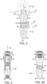
- Assembled tool 20 is shown in front view in Fig. 2 , in side view in Fig. 3 , and in vertical cross section in Fig. 4 .
- Fig. 4 some elements in the other Figures are absent, for clarity.
- the tool is described in terms of its orientation in the pictures of the Figures, but terms such as top, bottom, lower, etc. shall not be limiting since it will understood the tool may be used of stored in any orientation.
- the tool embodiment 20 is comprised of opposing side housings 22, 24 that are preferably made of a strong thermoset plastic, optionally a metal alloy or a carbon fiber epoxy composite.
- each housing has (a) an upper end called the pivot end which has a pivot hole 66C, 66D respectively that is centered on transverse axis 52; (b) a mid-boy portion, (c) a lower end comprised of spaced apart forks 54C, 54D respectively that define between them a U shape opening 65; and (d) a central portion with a through hole 61C, 61D respectively that is centered on transverse axis 50; and (d) a locking pin hole 67C, 67D respectively that is centered on transverse axis 48 which axis runs through the mid-body portion of the housing.
- the axes 48, 50, 52 are parallel to each other and intersect vertical axis CL of tool 20 when the tool is assembled.
- the housings are nearly mirror-identical, but for optional parts such as shield portions, any reciprocal male-female portions, and features that might be associated with a locking mechanism, such as described below.
- the arms, described next, have mirror shapes.
- Sometimes reference herein is made to a feature having a number that lacks a suffix letter. Such should be construed as a reference to all features which have the same number with a suffix letter.
- Arms 26, 28, which are also shown in Fig. 5 and 6 have mirror shapes.
- Each arm, as exemplified by Fig. 5 and arm 26, has an upper pivot end 33A where is the aforementioned pivot hole, a descending shank 35A that connects to a C shape portion 37A, at the bottom of which is the lower terminal end and jaw 42A.
- Each arm has a tab 44A, 44B respectively which descends from the bottom of the shank and is a portion of that which defines the C shape interior concavity of the arm.
- the shank and tabs and nubs mentioned below are features which generally extend in the lengthwise axis direction of the tool.
- the arms are preferably made of a strong steel, preferably a corrosion resisting (stainless) steel, such as AISI type 316 steel or 17-4PH steel.
- a corrosion resisting (stainless) steel such as AISI type 316 steel or 17-4PH steel.
- AISI type 316 steel or 17-4PH steel AISI type 316 steel or 17-4PH steel.
- alternative use may be made of a copper base alloy such as admiralty brass or bronze, or of high-strength engineered plastics and composite materials, including carbon-fiber reinforced plastics.
- each arm has an upper end (the pivot end) having pivot hole 66A, 66B that in the assembly lies along axis 52.
- a pin such as the pin 70 of a shackle 54 shown in phantom in Fig. 3 , can be inserted along axis 52 to keep the upper ends of the four parts 22, 24, 26, 28 aligned in pivotable fashion.
- the motion of the arms in the assembly may also be referred to as "partial-rotation" or "part-rotation.”
- an optional hollow rivet 72 shown in Fig. 1 and Fig. 4A .
- Other pin-like means or fasteners for holding the four principal parts 22, 24, 26, 28 together, may be used.
- use may be made of a threaded bolt, a solid rivet, or a pintle affixed to some other device. While for simplicity a pin or fastener is not shown on axis 52 in some assembly figures here, the presence of a pin should be implied by the artisan/reader.
- one or more of the housing or arms may have an integral transverse portion, such as an integral axle stub to fulfil the aforementioned pin or fastener function.
- the concavities of the arms partially overlap and the curved upper surfaces of the respective jaws 42A, 42B mate with each other in overlapping fashion, to provide a curved surface which defines the lower bound of space 68, which space is between the arms and is where an object such as handle 60 will be held during use of the tool 20.
- Tool 20 also has a locking mechanism comprised of locking pin holes 67A, 67B respectively in arms 26, 28.
- the locking pin holes lie along axis 48 and align with housing pin holes 67C, 67D, thus enabling pin 36 to be inserted, thereby holding the arms in the home position, as suggested/shown by Fig. 2 and Fig. 3 .
- Fig. 8 and Fig. 9 show another configuration of locking mechanism, as discussed below.
- a user can with one hand grasp the tool 20 and squeeze the arms 26, 28 above the vertical mid-point of the tool where the outer edges of the arms extend laterally from the opposing side housings.
- the user optionally can squeeze the arms to open the jaws sufficiently to allow them to close around an object such as handle 60 without the user applying the thrusting force associated with the aforementioned "stabbing.”
- Fig. 4A is a side view like Fig. 4 , with partial cross sectioning, showing device 20A which is like device 20 except for having a hollow rivet 72 as fastener at axis 52 to hold the housings together, and having a hollow rivet 74 at axis 50, which keeps in place spacer 30.
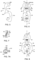
- Fig. 6 is a view of an assembly 21 that comprises arms 26, 28 in their home positions with the housings not pictured, for clarity.
- Fig. 7 is a horizontal plane cross section looking down along axis CL of the assembly 21.
- Fig. 6 and Fig. 7 (and Fig. 1 ) show compression coil spring 40 that is captured by the integral pins 38A, 38B respectively and is captured within the space between the arms. Spring 40 pushes on the arms so that jaws 42A, 42B move toward each other. With reference to Fig. 7 , the length of spring 40 runs at an angle to the plane between the mated arms. When the jaws are in their home position, the terminal or pointed top end of each jaw presses against the interior surface of one of the forks of a housing.
- coil spring 40 is one of several spring force means which may be used, for applying pivoting force to the arms, to cause their jaws to move apart from each other. be used.
- spring force may be applied to the arms by one or more torsion springs which circumscribe axis 52, for instance running around a solid or hollow pin or rivet that runs through holes 66A, 66B.
- one or more leaf springs may be used in to apply the desired pivoting force to the arms; for example a V shape leaf spring may replace the coil spring.
- Other known resilient devices may be used in substitution of coil spring 40 or for the other kinds of springs. For example, rubber or elastic polymer springs may be used.
- One or more than one spring means may be used cooperatively in a device.
- the lower/terminal end surfaces of the jaws may be nominally perpendicular to the length of the tool, or as shown in Fig. 2 , preferably curved so that when the jaws are in the home position, the lower end of the tool comprises a (curved) V shape contour surface 70.
- Fig. 8 is a side view like Fig. 6 , showing how, when tool 20 is forced (stabbed) against an object 60 (as shown by the arrow along the CL axis), contact of the object the V shape curved surface 70 thrusts the jaws 42A, 42B outwardly and away from each other as indicated by arrows A.
- a user may squeeze the arms toward each other in proximity to the coil spring location, thereby to open the jaws and engage an object. That may be useful where the object being engaged is non-rigid, such as a cable or a rope which is not taut, etc.
- Fig. 8 also illustrates how the extent of opening (outward motion) of the arms will be desirably limited, due to engagement of tabs 44A and 44B of the respective arms with bushing 30 which lies along axis 50.
- the spacer and forks comprise a preferred feature combination. As illustrated by the Fig. 1 exploded view along with Fig. 2 and Fig. 3 , spacer 30 is held in place along axis 50 by screw 32 and nut 34 which act both as fastener and as a shaft running through the spacer.
- spacer 50 may be mounted on one only of the housings; and, the spacer may comprise an integral feature projecting from one or both of the housing inward facing surfaces.
- the arm-limiting-function of a fastener or a fastener with surrounding spacer there is no appreciable difference and a claim reference to one shall comprise a reference to the other.
- Fig. 2 , 3 , and 6 illustrate how locking pin 36 may optionally be used to keep the arms (and thus the jaws) from opening when they are in their home position. Use of the locking pin can help prevent inadvertent release of an engaged object such as handle 60.
- Tool 221 is an embodiment comprised of arms held together by a fastener at axis 52; there are no housing parts. Tool 221 has features for limiting the closing and opening of the jaws to an extent comparable to that described for tool 20 where the limiting is achieved by using portions of the tool that are associated with the housings.
- Fig. 7A is a cross section like Fig. 7 , showing a portion of tool 221.
- Tool 221 is largely configured like tool 21 of Fig. 6 and comprises arms 226, 228 that are like arms 26, 28. The spring of tool 221 is omitted for clarity of illustration.
- Tool 221 comprises features which act as stop means and thereby limit the relative arm motion and associated relative jaws opening. More specifically, arm 226 has integral pin 238A which has a laterally projecting portion that is hit by integral pin 238B of arm 228 when arm 228 moves sufficiently close, thereby limiting jaw opening.
- tool 221 comprises changeable length linking means, connecting the arms.
- arm 228 is connected to arm 226 by lanyard 231, thereby limiting the separation distance of the arms and the of related jaw closing.
- Other linkages of equivalent function may be used in substitution of a lanyard.
- use may be made a slotted rigid link that extends pivotably from one arm to a pin on the other arm, with the pin within the slot.
- Tool 221 may further comprise a pair of housings, not shown, having pivot ends and pivot holes lying along the pivot axis, between which the mated arms 226, 227 are contained.
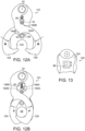
- Fig. 11 is an exploded view of portions of an alternate embodiment device 120 which is much like the device 20 shown in Fig. 2 , but which has a different locking mechanism.
- Fig. 12A and Fig. 12B are side views of the device shown in Fig. 11 , illustrating respectively how the device opens to receive an article and how the device closes and locks. Parts which correspond to those of Fig. 1 and other illustrations of device 20 have the same last two digits.
- housings 122, 124 capture arms 126, 128 by means of a not-shown fastener passing through the housing and arm holes on axis 50.
- Spacer 184 is interposed between the housing on axis 52, and a not-shown fastener may run within spacer.
- device 120 has a locking mechanism which comprises bar 76 that is guided for vertical CL axis motion (indicated by an arrow in Fig. 12B ) by fitting in slots 78 in the opposing side housings. Bar 76 is urged downwardly along the slot lengths by spring 80. Bar 76 preferably has a round end, shaped to press-fit receive rectangular shape button 86, to make it easier for a user to move the bar vertically against the spring bias.
- Each arm has a first nub, 182A, 182B respectively on the upper surface of the curved C shape portion, near the shank that runs to the pivot end; and each arm has a second nub 188A, 188B respectively, on the shank.
- Fig. 13 is a partial side view of tool 120 showing button 86 and, by the arrow. its vertical motion which moves bar 76. Latching means, to hold button 86 in a particular position may be provided.
- a slide button 86 may be present on both ends of the locking bar 76, pressed of screw-fastened onto the end of the bar.
- an embodiment of button 80 will have, on its left-right sides, molded resilient latch portions (e.g., small protrusions) that fit into detents in the edge of the housing depression that holds the button against the spring force, when the button is in uppermost position, as shown. (The latches and detents are not shown but are within ready comprehension of the artisan.)
- buttons 12B automatically locking the arms, so the object desirably cannot be removed from space 68 without manual intervention, to move the button, then to press inwardly on the shanks of the arms.
- the button configuration and means of latching may be carried out in different ways within the scope of invention.
- the button could be on the exterior of the housing and not in a recess
- the latching feature could be interior of the housing and associated with the bar and not the button.
- Fig. 10 illustrates another feature of the invention which enables engagement and capture of an object even though it is not being stabbed or contacted by relative motion along the central CL axis of tool 20.
- an off-center object 60 will push on the angle-curved terminal surface of arm jaw 42B and cause the jaw to move away from contact with the U shape opening at the lower end of the housing.
- the lower end of each housing comprises forks which have angled tips 56 that help guide tool 20 in engaging off-center object 60.
- the assembly 21 of Fig. 6 is an embodiment which could be utilized for grasping a load, notwithstanding the absence of the opposing side housings, and the resultant absence of features of exemplary tool 20. Modifications might be made to the assembly 21 to compensate for some of those missing features, for example, to limit the travel toward each other of the jaws 42A, 42B.
- a tool of the present invention may be fastened to the arm of a robotic device by means of a pin like pin 70.
- the invention tool fulfils objects of the invention.
- the tool can be engaged with a load by "stabbing" at the engagement point on an object, either manually or mechanically.
- the tool will not disengage when the load applied to an object fluctuates or goes to zero.
- the tool further optionally has a safety lock to inhibit inadvertent release of a load.
- the tool is compact and there is little tendency for snagging of a disengaged tool with extraneous objects.
- the tool enables easier one-hand manual engagement or disengagement.
- the tool can be manufactured on an economic mass basis.
Landscapes
- Engineering & Computer Science (AREA)
- General Engineering & Computer Science (AREA)
- Mechanical Engineering (AREA)
- Buckles (AREA)
- Hooks, Suction Cups, And Attachment By Adhesive Means (AREA)
- Clamps And Clips (AREA)
Claims (15)
- Ein Werkzeug (20) zum Greifen eines Gegenstandes (60), das eine Längsmittelachse und eine dazu senkrecht verlaufende Schwenkachse (52) sowie eine Anschlagachse (50) aufweist, wobei das Werkzeug aufweist:einen ersten Arm (26);einen zweiten Arm (28), der an dem ersten Arm (26) anliegt;wobei jeder Arm (26, 28) in der Längsachsenrichtung ein Schwenkende und einen mit dem Schwenkende verbundenen Schaft und ein mit dem Schaft verbundenes Griffende aufweist,wobei das Griffende eine Klammer (42A, 42B) aufweist, die sich an einem Endabschnitt des Arms befindet, wobei das Griffende C-förmig ist und eine Konkavität aufweist, die offen ist,wobei jedes Armschwenkende für eine Schwenkbewegung um die Schwenkachse (52) ausgebildet ist, was es dem Arm (26, 28) ermöglicht, von einer Grundposition des Arms in eine offene Armposition zu schwenken;wobei in der Grundposition des Arms die Klammer (42A) und die Konkavität eines Arms jeweils die Klammer (42B) und die Konkavität des anderen Arms überlappen und die zusammenpassenden Konkavitäten dadurch einen Raum definieren, in dem der Gegenstand (60) gegriffen werden kann;wobei, wenn sich die Klammern (42A, 42B) in der offenen Armposition befinden, die Klammern ausreichend beabstandet sind, um dem Gegenstand (60) zu ermöglichen, in den überlappenden Hohlraum zu gelangen;mindestens eine Feder (40), um die Arme in die Grundposition zu drücken;ein erstes Gehäuse (22);ein zweites Gehäuse (24), das von dem ersten Gehäuse (22) beabstandet ist und mit dem ersten Gehäuse durch ein Befestigungselement (32, 74) verbunden ist, das entlang der Anschlagachse verläuft;wobei die Arme (26, 28) schwenkbar und verschiebbar in dem Raum zwischen den Gehäusen (22, 24) aufgenommen sind;wobei sich ein Teil des Schafts jedes Arms (26, 28) seitlich von dem Raum zwischen den Gehäusen erstreckt, um ein manuelles Drücken auf den Arm zu ermöglichen, um den Arm gegen die Kraft der Feder (40) in Richtung der offenen Position zu bewegen;wobei jedes Gehäuse (22, 24) in der Längsachsenrichtung ein erstes Ende, das entlang der Schwenkachse positioniert ist, einen Mittelkörper und ein zweites Ende aufweist;wobei das zweite Ende ein Paar Gabeln (54) aufweist, die eine U-förmige Öffnung (65) aufweisen, die mit dem überlappenden konkaven Raum fluchtet, wenn sich die Arme in der Grundposition befinden; wobei jede Gabel (54) eine Spitze aufweist; dadurch gekennzeichnet,dass das Werkzeug (20) eine Verriegelungsachse aufweist und jeder Arm eine Nase (44A, 44B) aufweist, die sich in Längsrichtung von dem Schaft in den konkaven Raum des C-förmigen Griffendes erstreckt; und die Schwenkbewegung jedes Arms (26, 28) während des Öffnens der Klammern (42A, 42B) durch den Kontakt der Nase (44A, 44B) mit einem Befestigungselement (32, 34) oder einem Abstandshalter (30, 130), der um das Befestigungselement (32, 34) herum angeordnet ist, begrenzt wird.
- Werkzeug (20) nach Anspruch 1, dadurch gekennzeichnet, dass das Befestigungselement (32, 34) zwischen den Gehäusen (22, 24) entlang der Anschlagachse (50) verläuft, wobei sich die Nase (44A, 44B) jedes Arms von dem Griffabschnitt in einer im Wesentlichen Längsrichtung weg von dem Schwenkende erstreckt, um das Befestigungselement (32, 34) oder den Abstandshalter (30, 130) zu berühren und den Umfang der Armschwenkbewegung an der offenen Armposition zu begrenzen.
- Werkzeug (20) nach Anspruch 1, dadurch gekennzeichnet, dass jeder Arm (26, 28) eine spiegelbildliche Form des anderen Arms hat und jedes Gehäuse eine ähnliche äußere Form aufweist.
- Werkzeug (20) nach Anspruch 1, dadurch gekennzeichnet, dass es einen Stift (70), einen Hohlniet (72) oder ein weiteres Befestigungsmittel aufweist, das durch Löcher im Schwenkende jedes Arms und im ersten Ende jedes Gehäuses verläuft.
- Werkzeug (20) nach Anspruch 1, dadurch gekennzeichnet, dass die Arme (26, 28) in der Ausgangsstellung überlappende Klammern mit konturierten Oberflächen aufweisen, die eine V-förmige Konturfläche (70) bilden, die in Richtung des Endabschnitts des Werkzeugs zeigen.
- Werkzeug (20) nach Anspruch 1, dadurch gekennzeichnet, dass die Spitze jeder Gabel (54) eine Oberfläche aufweist, die relativ zur Längsmittelachse abgewinkelt ist, um jeden vom Endabschnitt des Werkzeugs berührten Gegenstand in die U-förmige Öffnung (65) des Gabelpaars zu führen.
- Werkzeug (20) nach Anspruch 1, dadurch gekennzeichnet, dass jedes Gehäuse eine Öffnung (67C, 67D) aufweist, die mit der Verriegelungsachse (48) ausgerichtet ist, und der Schaft jedes Arms eine Öffnung (67A, 67B) aufweist, die mit der Verriegelungsachse ausgerichtet ist, wenn sich die Arme (26, 28) in der Grundposition befinden; ferner einen entfernbaren Stift (3 6) aufweisend, der entlang der Verriegelungsachse verläuft und durch alle Löcher hindurchgeht.
- Werkzeug (20) nach Anspruch 1, dadurch gekennzeichnet, dass es Folgendes aufweist:einen ersten Nocken (182A, 182B) auf dem Griffteil jedes Arms in der Nähe des Schafts,wobei der erste Nocken im Wesentlichen in der Längsrichtung in Richtung des Schwenkendes des Arms vorsteht; und eine Verriegelungsstange (76), die quer zur Länge des Werkzeugs und zwischen Längsschlitzen (78) in den gegenüberliegenden Seitengehäusen verläuft, wobei die Verriegelungsstange (76) in der Längsrichtung des Werkzeugs beweglich positionierbar ist, um selektiv in den ersten Nocken (182A, 182B) jedes Arms einzugreifen und dadurch die Bewegung der Arme zu blockieren, wenn sich die Arme in der Grundposition befinden.
- Werkzeug (20) nach einem der vorhergehenden Ansprüche, dadurch gekennzeichnet, dass es mindestens einen Knopf (86) aufweist, der mit dem Ende der Verriegelungsstange (76) verbunden ist, wobei der mindestens eine Knopf (86) für einen verriegelnden Eingriff mit dem Gehäuse ausgebildet ist, wenn er sich in der nächstgelegenen Position zu einem Schwenkende eines Gehäuses befindet.
- Werkzeug (20) nach einem der vorhergehenden Ansprüche, dadurch gekennzeichnet, dass es einen zweiten Nocken (188A, 188B) aufweist, der seitlich in Richtung der Mittellinie des Werkzeugs für einen Schaft jedes Arms in einer Höhe vorsteht, die näher am Schwenkende liegt als die Verriegelungsstange (76), wenn sich jeder Arm in der Grundposition befindet, wobei jeder zweite Nocken (188A, 188B) so beschaffen ist, dass er die Verriegelungsstange berührt, wenn sich die Arme der offenen Position nähern, und dadurch die Verriegelungsstange (76) von den Schwenkenden der Gehäuse weg bewegt.
- Werkzeug (20) nach Anspruch 1, dadurch gekennzeichnet, dass jeder Arm einen integrierten Stift (38A, 38B) am Schaftabschnitt aufweist, wobei sich jeder Stift (38A, 38B) im Wesentlichen in einer Richtung quer zur Längsachse erstreckt, und wobei die Feder (40) zwischen den Stiften verläuft.
- Werkzeug (20) nach Anspruch 1, dadurch gekennzeichnet, dass jeder Arm einen Noppen (188A, 188B) aufweist, der sich von dem C-förmigen Abschnitt in der Hauptrichtung des Armschwenkendes erstreckt, ferner aufweisend:
eine bewegliche Verriegelungsstange (76), die zwischen den Gehäusen verläuft; wobei jedes Ende der Verriegelungsstange für eine seitliche Bewegung der Verriegelungsstange (76) entlang der zentralen Längsachse des Werkzeugs durch ein Element an jedem Gehäuse geführt wird, wobei die Verriegelungsstange in Richtung der U-förmigen Gehäuseöffnungen (62) elastisch vorgespannt ist; und wobei ein Eingreifen der Noppen in die Verriegelungsstange (72) die Arme in der Ausgangsposition hält; und wobei eine manuelle Bewegung der Verriegelungsstange gegen die Vorspannung der Feder (80) es den Armen ermöglicht, in die offene Position zu gelangen. - Werkzeug nach einem der vorhergehenden Ansprüche, dadurch gekennzeichnet, dass der Schaft jedes Arms eine Öffnung (67A, 67B) aufweist, die mit der Verriegelungsachse (48) ausgerichtet ist, wenn sich die Arme in der Grundposition befinden; ferner einen entfernbaren Stift (36) aufweisend, der entlang der Verriegelungsachse verläuft und durch die ausgerichteten Löcher (67A, 67B) geht.
- Werkzeug nach einem der vorhergehenden Ansprüche, dadurch gekennzeichnet, dass der erste Arm (26) und der zweite Arm (28) zwischen den Gehäusen (22, 24) aufgenommen sind.
- Verfahren zum Eingreifen eines Werkzeugs in einen Gegenstand (60), welches aufweist:Bereitstellen eines Werkzeugs (20) nach einem der vorhergehenden Ansprüche, wobei sich die Arme (26, 28) in der Grundposition befinden;Stoßen des Werkzeugs (20) auf den Gegenstand (60), so dass der Endabschnitt des Werkzeugs und die Konturfläche der Klammern (42A, 42B) den Gegenstand mit ausreichender Kraft berühren, um zu bewirken, dass jeder Arm (26, 28) um das Armschwenkende schwenkt, wodurch bewirkt wird, dass sich die Klammern (42A, 42B) trennen und es dem Gegenstand ermöglicht wird, in den angepassten Hohlraum einzutreten; und ermöglichen, dass die Feder (40) bewirkt, dass die Arme (26, 28) in die Grundposition zurückkehren.
Applications Claiming Priority (2)
| Application Number | Priority Date | Filing Date | Title |
|---|---|---|---|
| US201862642270P | 2018-03-13 | 2018-03-13 | |
| PCT/IB2019/000233 WO2019175659A1 (en) | 2018-03-13 | 2019-03-13 | Stab-connectable sister hook |
Publications (4)
| Publication Number | Publication Date |
|---|---|
| EP3765754A1 EP3765754A1 (de) | 2021-01-20 |
| EP3765754A4 EP3765754A4 (de) | 2021-12-01 |
| EP3765754C0 EP3765754C0 (de) | 2024-01-10 |
| EP3765754B1 true EP3765754B1 (de) | 2024-01-10 |
Family
ID=67903914
Family Applications (1)
| Application Number | Title | Priority Date | Filing Date |
|---|---|---|---|
| EP19767091.2A Active EP3765754B1 (de) | 2018-03-13 | 2019-03-13 | Stichverbindbarer schwesterhaken |
Country Status (6)
| Country | Link |
|---|---|
| US (1) | US11125266B2 (de) |
| EP (1) | EP3765754B1 (de) |
| CN (1) | CN112105827B (de) |
| AU (1) | AU2019235524B2 (de) |
| CA (1) | CA3093629C (de) |
| WO (1) | WO2019175659A1 (de) |
Families Citing this family (7)
| Publication number | Priority date | Publication date | Assignee | Title |
|---|---|---|---|---|
| US11293479B2 (en) * | 2019-05-21 | 2022-04-05 | Bowerbags Llc | Modular clipping system |
| CN110642142B (zh) * | 2019-09-29 | 2024-05-14 | 山西航天清华装备有限责任公司 | 移动站台车的起吊装置 |
| CN112249882A (zh) * | 2020-09-16 | 2021-01-22 | 川源(中国)机械有限公司 | 一种与着脱装置配合使用的水泵提升系统 |
| US11926507B1 (en) | 2021-08-18 | 2024-03-12 | The United States Of America As Represented By The Secretary Of The Navy | Modular unmanned line/tool emplacement (MULE) hook |
| CN116281553A (zh) * | 2022-12-12 | 2023-06-23 | 大冶特殊钢有限公司 | 烧结机台车快速更换专用吊具 |
| CN219248893U (zh) * | 2023-02-09 | 2023-06-27 | 佛山市拓润精密五金科技有限公司 | 一种带回位装置的连接扣 |
| DE102023001069A1 (de) * | 2023-03-14 | 2024-10-02 | Roland Brugger | Schließbare Lastengreifeinrichtung mit schwenkbaren Greifklinken |
Family Cites Families (18)
| Publication number | Priority date | Publication date | Assignee | Title |
|---|---|---|---|---|
| US346811A (en) | 1886-08-03 | Teeeitoey | ||
| US550189A (en) | 1895-11-19 | Harness snap-hook | ||
| GB189826923A (en) * | 1898-12-20 | 1899-10-28 | David Thomas Young | Improvements in Hooks for Cranes and other Lifting Machinery and Appliances. |
| US766140A (en) * | 1903-09-22 | 1904-07-26 | Niagara Falls Metal Stamping Works | Harness-hook. |
| US1668325A (en) | 1928-01-10 | 1928-05-01 | Kreutz Carl | Safety hook for tire chains |
| CH130226A (fr) * | 1928-02-28 | 1928-11-30 | Francois Planque | Porte-mousqueton. |
| GB316761A (en) | 1928-07-20 | 1929-08-08 | Clayton Aniline Co Ltd | Manufacture of a condensation product of ª‡-naphthylamine and acetaldehyde and the application thereof in the manufacture of vulcanised rubber |
| GB316767A (en) * | 1928-07-26 | 1929-08-08 | Bengtsson Svante | Improvements relating to detachable links for harness and the like |
| US2234853A (en) * | 1940-04-24 | 1941-03-11 | John T Brueggeman | Snap hook |
| JPH0866294A (ja) * | 1994-08-31 | 1996-03-12 | Okuda Seisakusho:Kk | ハンガー掛け |
| AP842A (en) | 1995-12-04 | 2000-06-06 | Bellambie Mining And Industrial Ltd | Safety detaching hooks. |
| ITMI981697A1 (it) | 1998-07-22 | 2000-01-22 | Kong Spa | Connettore con chiusura a scatto |
| US6463640B1 (en) | 2000-01-13 | 2002-10-15 | Douglas J. Toth | Strap connecting buckle |
| TW517792U (en) * | 2001-05-04 | 2003-01-11 | Chung Shan Inst Of Science | Fast detaching hook |
| JP4056003B2 (ja) * | 2003-08-07 | 2008-03-05 | 昭八 和久田 | 被吊り下げ物落下防止用ワンハンドクリップ |
| FR2903395B1 (fr) * | 2006-07-04 | 2009-04-17 | C2E Entpr | Crochet de levage a commande a distance autonome en energie |
| US9488203B2 (en) | 2014-03-05 | 2016-11-08 | Enginuity Inc. | Disconnectable subsea connector |
| US10004926B2 (en) * | 2016-10-18 | 2018-06-26 | Meyer Ostrobrod | Remote overhead anchor |
-
2019
- 2019-03-13 CA CA3093629A patent/CA3093629C/en active Active
- 2019-03-13 WO PCT/IB2019/000233 patent/WO2019175659A1/en not_active Ceased
- 2019-03-13 CN CN201980019220.XA patent/CN112105827B/zh active Active
- 2019-03-13 US US16/352,635 patent/US11125266B2/en active Active
- 2019-03-13 EP EP19767091.2A patent/EP3765754B1/de active Active
- 2019-03-13 AU AU2019235524A patent/AU2019235524B2/en active Active
Also Published As
| Publication number | Publication date |
|---|---|
| CN112105827B (zh) | 2022-09-16 |
| AU2019235524B2 (en) | 2025-03-06 |
| EP3765754C0 (de) | 2024-01-10 |
| CA3093629C (en) | 2024-01-02 |
| US20190285110A1 (en) | 2019-09-19 |
| AU2019235524A1 (en) | 2020-10-15 |
| CN112105827A (zh) | 2020-12-18 |
| WO2019175659A1 (en) | 2019-09-19 |
| EP3765754A1 (de) | 2021-01-20 |
| CA3093629A1 (en) | 2019-09-19 |
| US11125266B2 (en) | 2021-09-21 |
| EP3765754A4 (de) | 2021-12-01 |
Similar Documents
| Publication | Publication Date | Title |
|---|---|---|
| EP3765754B1 (de) | Stichverbindbarer schwesterhaken | |
| EP3426870B1 (de) | Hakenverschluss mit hohem versatz | |
| EP2620258B1 (de) | Verriegelungszangen mit Griffsperrmechanismus | |
| US9844857B2 (en) | Locking pliers with handle locking mechanism | |
| EP1050255A2 (de) | Durch Schwerkraft verriegelbare Zange | |
| US20140121072A1 (en) | Hook Assemblies for Exercise Machines, Exercise Machines Including Such Hook Assemblies, and Related Methods | |
| EP1591204B1 (de) | Von Hand betätigbare und verriegelbare Spannvorrichtung | |
| US8756771B1 (en) | Locking clip assembly | |
| EP4081075B1 (de) | Faltbares greifwerkzeug | |
| US20050077736A1 (en) | Spring open latch clamp | |
| US20160318157A1 (en) | Toggle clamp with locking mechanism | |
| CN115013409B (zh) | 包括用于螺杆的联接器的结构紧固件 | |
| EP0061257A1 (de) | Sperrhaken für Gerüste | |
| CN106132644B (zh) | 珠宝工具 | |
| HK40037568B (en) | Stab-connectable sister hook | |
| HK40037568A (en) | Stab-connectable sister hook | |
| US4474396A (en) | Wood stove and fireplace log handler | |
| EP3002092B1 (de) | Öffnendes und schliessendes arbeitswerkzeug | |
| CN223800004U (zh) | 一种快挂挂钩 | |
| EP3566810B1 (de) | Kolbenklemme mit einem hebelverschluss | |
| CN120731144A (zh) | 夹持工具 | |
| JPH0711923U (ja) | 傘の摺動ろくろ停止構造 | |
| WO2014040114A1 (en) | Improved snap hook | |
| HK1037855A (en) | Gravity lockable tongs |
Legal Events
| Date | Code | Title | Description |
|---|---|---|---|
| STAA | Information on the status of an ep patent application or granted ep patent |
Free format text: STATUS: THE INTERNATIONAL PUBLICATION HAS BEEN MADE |
|
| PUAI | Public reference made under article 153(3) epc to a published international application that has entered the european phase |
Free format text: ORIGINAL CODE: 0009012 |
|
| STAA | Information on the status of an ep patent application or granted ep patent |
Free format text: STATUS: REQUEST FOR EXAMINATION WAS MADE |
|
| 17P | Request for examination filed |
Effective date: 20201001 |
|
| AK | Designated contracting states |
Kind code of ref document: A1 Designated state(s): AL AT BE BG CH CY CZ DE DK EE ES FI FR GB GR HR HU IE IS IT LI LT LU LV MC MK MT NL NO PL PT RO RS SE SI SK SM TR |
|
| AX | Request for extension of the european patent |
Extension state: BA ME |
|
| RIN1 | Information on inventor provided before grant (corrected) |
Inventor name: GARVEY, BENJAMIN Inventor name: GUINDON, JEAN-MARC Inventor name: MANUGE, LOUIS-PHILLIPE Inventor name: MUSSETT, JONATHAN Inventor name: TROWER, ALASTAIR |
|
| DAV | Request for validation of the european patent (deleted) | ||
| DAX | Request for extension of the european patent (deleted) | ||
| A4 | Supplementary search report drawn up and despatched |
Effective date: 20211102 |
|
| RIC1 | Information provided on ipc code assigned before grant |
Ipc: F16G 11/14 20060101ALI20211026BHEP Ipc: B66C 1/36 20060101ALI20211026BHEP Ipc: B63B 21/00 20060101ALI20211026BHEP Ipc: F16B 45/06 20060101AFI20211026BHEP |
|
| P01 | Opt-out of the competence of the unified patent court (upc) registered |
Effective date: 20230515 |
|
| GRAP | Despatch of communication of intention to grant a patent |
Free format text: ORIGINAL CODE: EPIDOSNIGR1 |
|
| STAA | Information on the status of an ep patent application or granted ep patent |
Free format text: STATUS: GRANT OF PATENT IS INTENDED |
|
| INTG | Intention to grant announced |
Effective date: 20230808 |
|
| GRAS | Grant fee paid |
Free format text: ORIGINAL CODE: EPIDOSNIGR3 |
|
| GRAA | (expected) grant |
Free format text: ORIGINAL CODE: 0009210 |
|
| STAA | Information on the status of an ep patent application or granted ep patent |
Free format text: STATUS: THE PATENT HAS BEEN GRANTED |
|
| AK | Designated contracting states |
Kind code of ref document: B1 Designated state(s): AL AT BE BG CH CY CZ DE DK EE ES FI FR GB GR HR HU IE IS IT LI LT LU LV MC MK MT NL NO PL PT RO RS SE SI SK SM TR |
|
| REG | Reference to a national code |
Ref country code: GB Ref legal event code: FG4D |
|
| REG | Reference to a national code |
Ref country code: CH Ref legal event code: EP |
|
| REG | Reference to a national code |
Ref country code: DE Ref legal event code: R096 Ref document number: 602019044917 Country of ref document: DE |
|
| REG | Reference to a national code |
Ref country code: IE Ref legal event code: FG4D |
|
| RAP4 | Party data changed (patent owner data changed or rights of a patent transferred) |
Owner name: ENGINUITY INC. |
|
| U01 | Request for unitary effect filed |
Effective date: 20240206 |
|
| U07 | Unitary effect registered |
Designated state(s): AT BE BG DE DK EE FI FR IT LT LU LV MT NL PT SE SI Effective date: 20240219 |
|
| P04 | Withdrawal of opt-out of the competence of the unified patent court (upc) registered |
Effective date: 20240214 |
|
| U20 | Renewal fee for the european patent with unitary effect paid |
Year of fee payment: 6 Effective date: 20240315 |
|
| PG25 | Lapsed in a contracting state [announced via postgrant information from national office to epo] |
Ref country code: IS Free format text: LAPSE BECAUSE OF FAILURE TO SUBMIT A TRANSLATION OF THE DESCRIPTION OR TO PAY THE FEE WITHIN THE PRESCRIBED TIME-LIMIT Effective date: 20240510 |
|
| PG25 | Lapsed in a contracting state [announced via postgrant information from national office to epo] |
Ref country code: GR Free format text: LAPSE BECAUSE OF FAILURE TO SUBMIT A TRANSLATION OF THE DESCRIPTION OR TO PAY THE FEE WITHIN THE PRESCRIBED TIME-LIMIT Effective date: 20240411 |
|
| PG25 | Lapsed in a contracting state [announced via postgrant information from national office to epo] |
Ref country code: HR Free format text: LAPSE BECAUSE OF FAILURE TO SUBMIT A TRANSLATION OF THE DESCRIPTION OR TO PAY THE FEE WITHIN THE PRESCRIBED TIME-LIMIT Effective date: 20240110 Ref country code: RS Free format text: LAPSE BECAUSE OF FAILURE TO SUBMIT A TRANSLATION OF THE DESCRIPTION OR TO PAY THE FEE WITHIN THE PRESCRIBED TIME-LIMIT Effective date: 20240410 |
|
| PG25 | Lapsed in a contracting state [announced via postgrant information from national office to epo] |
Ref country code: ES Free format text: LAPSE BECAUSE OF FAILURE TO SUBMIT A TRANSLATION OF THE DESCRIPTION OR TO PAY THE FEE WITHIN THE PRESCRIBED TIME-LIMIT Effective date: 20240110 |
|
| PG25 | Lapsed in a contracting state [announced via postgrant information from national office to epo] |
Ref country code: RS Free format text: LAPSE BECAUSE OF FAILURE TO SUBMIT A TRANSLATION OF THE DESCRIPTION OR TO PAY THE FEE WITHIN THE PRESCRIBED TIME-LIMIT Effective date: 20240410 Ref country code: IS Free format text: LAPSE BECAUSE OF FAILURE TO SUBMIT A TRANSLATION OF THE DESCRIPTION OR TO PAY THE FEE WITHIN THE PRESCRIBED TIME-LIMIT Effective date: 20240510 Ref country code: HR Free format text: LAPSE BECAUSE OF FAILURE TO SUBMIT A TRANSLATION OF THE DESCRIPTION OR TO PAY THE FEE WITHIN THE PRESCRIBED TIME-LIMIT Effective date: 20240110 Ref country code: GR Free format text: LAPSE BECAUSE OF FAILURE TO SUBMIT A TRANSLATION OF THE DESCRIPTION OR TO PAY THE FEE WITHIN THE PRESCRIBED TIME-LIMIT Effective date: 20240411 Ref country code: ES Free format text: LAPSE BECAUSE OF FAILURE TO SUBMIT A TRANSLATION OF THE DESCRIPTION OR TO PAY THE FEE WITHIN THE PRESCRIBED TIME-LIMIT Effective date: 20240110 |
|
| PG25 | Lapsed in a contracting state [announced via postgrant information from national office to epo] |
Ref country code: PL Free format text: LAPSE BECAUSE OF FAILURE TO SUBMIT A TRANSLATION OF THE DESCRIPTION OR TO PAY THE FEE WITHIN THE PRESCRIBED TIME-LIMIT Effective date: 20240110 |
|
| PG25 | Lapsed in a contracting state [announced via postgrant information from national office to epo] |
Ref country code: PL Free format text: LAPSE BECAUSE OF FAILURE TO SUBMIT A TRANSLATION OF THE DESCRIPTION OR TO PAY THE FEE WITHIN THE PRESCRIBED TIME-LIMIT Effective date: 20240110 |
|
| REG | Reference to a national code |
Ref country code: DE Ref legal event code: R097 Ref document number: 602019044917 Country of ref document: DE |
|
| PG25 | Lapsed in a contracting state [announced via postgrant information from national office to epo] |
Ref country code: SM Free format text: LAPSE BECAUSE OF FAILURE TO SUBMIT A TRANSLATION OF THE DESCRIPTION OR TO PAY THE FEE WITHIN THE PRESCRIBED TIME-LIMIT Effective date: 20240110 |
|
| PG25 | Lapsed in a contracting state [announced via postgrant information from national office to epo] |
Ref country code: CZ Free format text: LAPSE BECAUSE OF FAILURE TO SUBMIT A TRANSLATION OF THE DESCRIPTION OR TO PAY THE FEE WITHIN THE PRESCRIBED TIME-LIMIT Effective date: 20240110 |
|
| PG25 | Lapsed in a contracting state [announced via postgrant information from national office to epo] |
Ref country code: SK Free format text: LAPSE BECAUSE OF FAILURE TO SUBMIT A TRANSLATION OF THE DESCRIPTION OR TO PAY THE FEE WITHIN THE PRESCRIBED TIME-LIMIT Effective date: 20240110 |
|
| PG25 | Lapsed in a contracting state [announced via postgrant information from national office to epo] |
Ref country code: SM Free format text: LAPSE BECAUSE OF FAILURE TO SUBMIT A TRANSLATION OF THE DESCRIPTION OR TO PAY THE FEE WITHIN THE PRESCRIBED TIME-LIMIT Effective date: 20240110 Ref country code: SK Free format text: LAPSE BECAUSE OF FAILURE TO SUBMIT A TRANSLATION OF THE DESCRIPTION OR TO PAY THE FEE WITHIN THE PRESCRIBED TIME-LIMIT Effective date: 20240110 Ref country code: RO Free format text: LAPSE BECAUSE OF FAILURE TO SUBMIT A TRANSLATION OF THE DESCRIPTION OR TO PAY THE FEE WITHIN THE PRESCRIBED TIME-LIMIT Effective date: 20240110 Ref country code: CZ Free format text: LAPSE BECAUSE OF FAILURE TO SUBMIT A TRANSLATION OF THE DESCRIPTION OR TO PAY THE FEE WITHIN THE PRESCRIBED TIME-LIMIT Effective date: 20240110 |
|
| REG | Reference to a national code |
Ref country code: CH Ref legal event code: PL |
|
| PLBE | No opposition filed within time limit |
Free format text: ORIGINAL CODE: 0009261 |
|
| STAA | Information on the status of an ep patent application or granted ep patent |
Free format text: STATUS: NO OPPOSITION FILED WITHIN TIME LIMIT |
|
| PG25 | Lapsed in a contracting state [announced via postgrant information from national office to epo] |
Ref country code: MC Free format text: LAPSE BECAUSE OF FAILURE TO SUBMIT A TRANSLATION OF THE DESCRIPTION OR TO PAY THE FEE WITHIN THE PRESCRIBED TIME-LIMIT Effective date: 20240110 |
|
| PG25 | Lapsed in a contracting state [announced via postgrant information from national office to epo] |
Ref country code: MC Free format text: LAPSE BECAUSE OF FAILURE TO SUBMIT A TRANSLATION OF THE DESCRIPTION OR TO PAY THE FEE WITHIN THE PRESCRIBED TIME-LIMIT Effective date: 20240110 |
|
| 26N | No opposition filed |
Effective date: 20241011 |
|
| P05 | Withdrawal of opt-out of the competence of the unified patent court (upc) changed |
Free format text: CASE NUMBER: APP_8164/2024 Effective date: 20240219 |
|
| PG25 | Lapsed in a contracting state [announced via postgrant information from national office to epo] |
Ref country code: IE Free format text: LAPSE BECAUSE OF NON-PAYMENT OF DUE FEES Effective date: 20240313 |
|
| PG25 | Lapsed in a contracting state [announced via postgrant information from national office to epo] |
Ref country code: IE Free format text: LAPSE BECAUSE OF NON-PAYMENT OF DUE FEES Effective date: 20240313 Ref country code: CH Free format text: LAPSE BECAUSE OF NON-PAYMENT OF DUE FEES Effective date: 20240331 |
|
| U20 | Renewal fee for the european patent with unitary effect paid |
Year of fee payment: 7 Effective date: 20250312 |
|
| PGFP | Annual fee paid to national office [announced via postgrant information from national office to epo] |
Ref country code: NO Payment date: 20250319 Year of fee payment: 7 |
|
| PGFP | Annual fee paid to national office [announced via postgrant information from national office to epo] |
Ref country code: GB Payment date: 20250311 Year of fee payment: 7 |
|
| PG25 | Lapsed in a contracting state [announced via postgrant information from national office to epo] |
Ref country code: CY Free format text: LAPSE BECAUSE OF FAILURE TO SUBMIT A TRANSLATION OF THE DESCRIPTION OR TO PAY THE FEE WITHIN THE PRESCRIBED TIME-LIMIT; INVALID AB INITIO Effective date: 20190313 |
|
| PG25 | Lapsed in a contracting state [announced via postgrant information from national office to epo] |
Ref country code: HU Free format text: LAPSE BECAUSE OF FAILURE TO SUBMIT A TRANSLATION OF THE DESCRIPTION OR TO PAY THE FEE WITHIN THE PRESCRIBED TIME-LIMIT; INVALID AB INITIO Effective date: 20190313 |
|
| PG25 | Lapsed in a contracting state [announced via postgrant information from national office to epo] |
Ref country code: TR Free format text: LAPSE BECAUSE OF FAILURE TO SUBMIT A TRANSLATION OF THE DESCRIPTION OR TO PAY THE FEE WITHIN THE PRESCRIBED TIME-LIMIT Effective date: 20240110 |