EP1050255A2 - Durch Schwerkraft verriegelbare Zange - Google Patents
Durch Schwerkraft verriegelbare Zange Download PDFInfo
- Publication number
- EP1050255A2 EP1050255A2 EP99203236A EP99203236A EP1050255A2 EP 1050255 A2 EP1050255 A2 EP 1050255A2 EP 99203236 A EP99203236 A EP 99203236A EP 99203236 A EP99203236 A EP 99203236A EP 1050255 A2 EP1050255 A2 EP 1050255A2
- Authority
- EP
- European Patent Office
- Prior art keywords
- pin
- tongs
- gravity
- arm
- arms
- Prior art date
- Legal status (The legal status is an assumption and is not a legal conclusion. Google has not performed a legal analysis and makes no representation as to the accuracy of the status listed.)
- Withdrawn
Links
Images
Classifications
-
- A—HUMAN NECESSITIES
- A47—FURNITURE; DOMESTIC ARTICLES OR APPLIANCES; COFFEE MILLS; SPICE MILLS; SUCTION CLEANERS IN GENERAL
- A47G—HOUSEHOLD OR TABLE EQUIPMENT
- A47G21/00—Table-ware
- A47G21/10—Sugar tongs; Asparagus tongs; Other food tongs
-
- A—HUMAN NECESSITIES
- A47—FURNITURE; DOMESTIC ARTICLES OR APPLIANCES; COFFEE MILLS; SPICE MILLS; SUCTION CLEANERS IN GENERAL
- A47J—KITCHEN EQUIPMENT; COFFEE MILLS; SPICE MILLS; APPARATUS FOR MAKING BEVERAGES
- A47J43/00—Implements for preparing or holding food, not provided for in other groups of this subclass
- A47J43/28—Other culinary hand implements, e.g. spatulas, pincers, forks or like food holders, ladles, skimming ladles, cooking spoons; Spoon-holders attached to cooking pots
- A47J43/283—Tongs; Devices for picking, holding or rotating food
Definitions
- the present invention relates to grasping devices such as tongs used to handle food, which may be locked in a closed position for storage using a gravity-based locking means.
- Spring-loaded tongs are commonly used to handle food and provide a convenient way to grasp objects to be temporarily transported.
- the spring is biased to urge the tongs to an open position such that they are ready for immediate use.
- tongs take up a significant amount of space if left in the open condition. This is typically not a problem when the tongs are used, but becomes undesirable when the tongs are to be stored. If the tongs are compressed and placed in a drawer, the spring action of the tongs may cause them to open rendering the drawer difficult to open.
- U.S. Patent No 5,199,756 discloses a movable lock actuated by manually sliding a locking plate to a position where the tong arms are restricted from moving. This locking plate is engaged or disengaged by applying force to the plate, requiring the user to hold the tongs in a closed position with one hand while sliding the locking plate into an engaged or disengaged position with the other hand.
- External means tot retaining the tongs in a closed position may be applied such as provided by rubber bands or some other method of securing the tong anus in a closed position. These methods are less than satisfactory and may lead to the tongs springing open upon failure or dislodging of this external restraint. Rubber bands are likewise unsuitable because the rubber breaks down over time leaving residue on the utensil.
- U.S. Patent No. 4,609,132 discloses a gravity-based locking device used for hanging clothes.
- This hanger provides a locking mechanism that uses a cylinder placed between two angled surfaces that rides on a shaft.
- the mechanism used can trap clothes of variable thicknesses between the first and second arms while providing a suitable operation for a hanger.
- the '132 mechanism while providing a method for a variable thickness gravity based locking mechanism does not offer a suitable mechanism for use in tongs since the tongs lock in only a fully closed position.
- the tongs comprise a first arm and a second arm each comprising a hinge end and a grasping end.
- Hinge means is provided for pivotably connecting the first and second arms together at the hinge ends, so that the arms can pivot between an open position and closed position.
- Spring means are included for biasing the arms in an open position.
- the gravity locking means comprises a captured pin means attached to the first arm and an aperture means attached to the second arm.
- the captured pin means has a pin means that moves under the effects of gravity within a containment means having a contained range of motion.
- the aperture means of the second arm has an engagement area located on a slideable surface.
- the aperture means may comprise an elongated aperture where the pin is in slideable contact with the slideable surface of the aperture means.
- the tongs arms are made of stainless steel, but other implementations may utilize plastic, ceramic or wood or any other material providing the strength to allow the tongs to grasp an object.
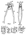
- the tongs have a first arm 10 and a second arm 20 where the first arm has a hinge end 12 and a grasping end 14 and the second arm has a hinge end 22 and a grasping end 24.
- the grasping ends have the general configuration as shown in Figure 1, but other grasping shapes may also be employed.
- a hinge pin 30 is located at the hinge end of the first arm 12 and second arm 22 to join the hinge ends together.
- a spring means 40 is used to apply force to bias the arms in an open position as shown in Figure 1.
- the spring means is a wound wire made of spring steel which must be compressed from its natural state during assembly of the tongs to allow sufficient force to cause the arms to remain in the open position.
- Other materials or types of force generating mechanisms may be employed to achieve the same effect.
- the hinge pin 30 is used to retain the spring 40 by placing the pin through the central winding 42 of the spring 40.
- a gravity locking mechanism is employed to retain the tongs in a closed position such that the tongs may be easily handled or stored.
- the gravity locking mechanism as shown in Figure 3 comprises a first member attached to the first arm 10 and a second member attached to the second arm 20 that mutually cooperate to lock and unlock the tongs based on a simple one-handed mode of operation.
- the first member comprises captured pin means 50 which is made of a pin means 70 and containment means 52.
- the pin means and the containment means are made of stainless steel.
- the containment means is a simple bracket 52 attached to the first arm 10 along one edge 56 and may generally have a 'C' shape.
- the C-shaped containment means 52 has a first bracket leg 54, a base 56 and a second bracket leg 58.
- the base 56 of the containment means 52 may be attached to the first arm 10 by either a weld joint, adhesives, rivets or other mechanical joining method as is known by those skilled in the art.
- the first bracket leg 54 and second bracket leg 58 have apertures 60, 62 located in a straight line such that an axis is formed through which a pin may be inserted.
- the pin means 70 may be made from a straight pin having a length longer than the opening of the containment means such that the pin ends 72, 76 extend beyond the first bracket leg 54 and second bracket leg 58 (see Figure 4).
- the middle region 74 of the pin is of a larger size than the apertures 60, 62 of the bracket legs such that the pin cannot be removed but may be free to travel for a limited distance between the first bracket leg 54 and the second bracket leg 58.
- the ends of the pin 72,76 are smooth and the middle region 74 is increased in size for a limited portion thereof corresponding to the desired free travel of the pin 70.
- the pin means is allowed to travel within the containment means based on gravity where the middle region 74 may be located against the first bracket leg 54 or the second bracket leg 58 based on the orientation of the containment means.
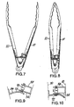
- the second member of the gravity locking means is the aperture means 80 which comprises a slideable surface 84,86 an engagement area 90 and a joining area 82 (see Figure 5, 6).
- the aperture means is attached to the second arm of the tongs by attaching the joining area 82 to the second arm 20 such that the aperture means is located in substantial alignment with the captured pin means 50 (see Figure 5).
- the slideable surface of the aperture means 80 comprises a substantially straight portion 84 and a curved portion 86 such that the curved portion 86 is a constant radial distance from the hinge 30.
- the engagement area 90 of the aperture means comprises an aperture located on the slideable surface 84 in alignment with the pin means 70 when the tongs are in a closed position.
- the diameter of the aperture 90 is slightly larger than the pin diameter 72.
- the diameter of the aperture 90 may be slotted with the length of the slot aligned with the direction of closure of the tong arms.
- the user grasps the tongs in a typical manner and approaches the target material to be picked-up from above with the grasping ends oriented below the hinged ends of the tongs. As the user presses the tong ends together, the grasping ends engage the target material. During this operation, since the tongs are oriented as shown in Figure 2, the locking mechanism is not engaged because the weight of the pin disposes the pin toward the lowest point (see Figure 6) where a noticeable gap 110 is maintained between the pin end 72 and the slideable surfaces 84, 86.
- the gravity locking mechanism of this invention locks in a closed position by changing the orientation of the locking tongs so that the pin means 70 slides from a disengaged position to an engaged position and depressing the tong arms toward each other a sufficient distance to allow the pin means 70 to be aligned with the engagement area 90 of the aperture means. These steps may be performed in any order. As previously described the pin means will slide from the disengaged position to the engaged position by changing the orientation of the tongs.
- Figure 7, 8, and 9 and 10 show the tongs and locking mechanism in an inverted orientation suitable for engagement.
- the user may press the tong grasping ends 14, 24 toward each other by applying pressure to the tong arms 10,20 and move the grasping ends above the horizontal plane with respect to the gravity locking means in order for the pin means to overcome frictional resistance between the pin means and the containment means as previously described.
- the user may orient the grasping ends of the tong arms as just described and then apply pressure to the tong arms.
- the tong arms When the tong arms have closed sufficiently to allow the pin means to engage the aperture means the pin means will slide into the aperture means.
- the engaged pin means is held in place by the lateral forces translated from the spring means 40 through the tong arms through the two members of the locking mechanism. This lateral force exists as long as the tongs are in the closed position.
- the tongs may be oriented in any attitude where they will remain closed.
- the user To open the locked tongs the user must orient the grasping ends 14, 24 at an attitude lower than the gravity locking means 50, 80 and slightly depress the tong arms 10, 20 to relieve the lateral force felt by the pin means so the pin means may simply slide under its own weight.
- tongs are made of formed stainless steel where one arm is formed to fit inside the other arm at the hinged end and are held together by the hinge pin so that they may rotate about the hinge with little interference.
- the tong grasping ends have scalloped edges.
- the surface of the tongs have a smooth exterior, but may be modified to have external gripping areas which may include ridges or roughend areas.
- the hinged end of the tongs have a range limiting edge 100 located near the hinge, to restrict the separation of the grasping ends of the tongs. When the tongs are in the open position the range limiting edge 100 controls the relative angle between the tong arms by banking on the interior surface 115 of the opposing tong arm (see figure 1).
- the locking mechanism is useable in other applications where the locking mechanism is adjusted to lock the mechanism in the same manner as described in this specification. It is also possible to modify the location of the aperture means so that it is located below the pin capture means. This would cause the mechanism to lock when the operable mode would require a device to lock such that it is unlocked when the operable ends are oriented above the gravity locking mechanism.
- the hinged end of the first tong arm 10 has a second aperture 120 (see Figure 1) located at the end of the tong arm to allow the tongs to be hung on a protruding object such as a hook or nail.
- first and second arms may be joined at one end by a leaf spring, thus integrating the functions of the pin 30 and spring 40.
- the leaf spring may be made from any suitable resilient or elastically deformable material such as a steel or plastics material.
- the leaf spring may be made integral with the first and second arms and may be in the form of a U-shape.
Landscapes
- Engineering & Computer Science (AREA)
- Mechanical Engineering (AREA)
- Food Science & Technology (AREA)
- Table Equipment (AREA)
- Food-Manufacturing Devices (AREA)
Applications Claiming Priority (2)
| Application Number | Priority Date | Filing Date | Title |
|---|---|---|---|
| US310292 | 1994-09-22 | ||
| US09/310,292 US6092847A (en) | 1999-05-12 | 1999-05-12 | Gravity lockable tongs |
Publications (2)
| Publication Number | Publication Date |
|---|---|
| EP1050255A2 true EP1050255A2 (de) | 2000-11-08 |
| EP1050255A3 EP1050255A3 (de) | 2002-02-13 |
Family
ID=23201836
Family Applications (1)
| Application Number | Title | Priority Date | Filing Date |
|---|---|---|---|
| EP99203236A Withdrawn EP1050255A3 (de) | 1999-05-12 | 1999-10-04 | Durch Schwerkraft verriegelbare Zange |
Country Status (2)
| Country | Link |
|---|---|
| US (1) | US6092847A (de) |
| EP (1) | EP1050255A3 (de) |
Cited By (2)
| Publication number | Priority date | Publication date | Assignee | Title |
|---|---|---|---|---|
| GB2416322A (en) * | 2004-07-21 | 2006-01-25 | Peter Michael Woodworth | Scissors or tongs with pivot and spring |
| RU189492U1 (ru) * | 2019-04-04 | 2019-05-23 | Сергей Викторович Бодарев | Средство для захвата продуктов питания |
Families Citing this family (52)
| Publication number | Priority date | Publication date | Assignee | Title |
|---|---|---|---|---|
| US6536819B2 (en) * | 2001-02-28 | 2003-03-25 | Columbia Insurance Company | Tongs with clamp and stop means |
| US6568728B1 (en) * | 2002-02-06 | 2003-05-27 | Yu-Tzu Wang | Positioning structure of grill tongs |
| US6749229B2 (en) | 2002-08-22 | 2004-06-15 | Rock Ridge Technologies, Co. | Machine insertable promotional card |
| JP4391946B2 (ja) * | 2002-10-31 | 2009-12-24 | ブラウン アンド カンパニー リミテッド | ロック可能なトング |
| USD488032S1 (en) | 2003-04-21 | 2004-04-06 | Wki Holding Company, Inc. | Tongs' heads |
| US7086676B2 (en) * | 2003-05-29 | 2006-08-08 | Dart Industries Inc, | Multi-purpose tongs having an incremental cam |
| USD491028S1 (en) | 2003-05-29 | 2004-06-08 | Dart Industries Inc. | Tongs |
| US20040245790A1 (en) * | 2003-06-04 | 2004-12-09 | William Thomas | Janitor tweezers |
| USD510845S1 (en) | 2004-03-10 | 2005-10-25 | Chef'n Corporation | Tongs |
| US6869117B1 (en) | 2004-07-07 | 2005-03-22 | Alvin S. Blum | Magnetic locking tongs |
| DE102004050632A1 (de) * | 2004-10-18 | 2006-04-20 | Metallwarenfabrik Marktoberdorf Gmbh & Co. Kg | Servierzange |
| USD517381S1 (en) * | 2004-12-14 | 2006-03-21 | Michael Graves Design Group, Inc. | Tong |
| US6984144B1 (en) | 2004-12-22 | 2006-01-10 | Xerox Corporation | Low effort, high reliability quick coupling mechanism |
| US7418766B2 (en) * | 2004-12-22 | 2008-09-02 | Xerox Corporation | Hinge with tandem pivot structure motion lock and override |
| US7287791B2 (en) * | 2005-04-14 | 2007-10-30 | Carolina Raymond H | Wing holder |
| US7036859B1 (en) * | 2005-04-25 | 2006-05-02 | Hung Chia Liao | Lifting device for pot or pan |
| US7531197B2 (en) * | 2005-05-23 | 2009-05-12 | Kandy Kastle, Inc. | Toy candy dispensing assembly with tongs |
| USD531463S1 (en) * | 2005-08-12 | 2006-11-07 | Cambro Manufacturing Co. | Food service tongs |
| USD557084S1 (en) | 2005-11-17 | 2007-12-11 | Helen Of Troy Limited | Tong head |
| US7448660B2 (en) * | 2005-11-18 | 2008-11-11 | Helen Of Troy Limited | Tongs with encapsulated locking mechanism |
| US7384084B2 (en) * | 2005-12-21 | 2008-06-10 | Mcilrath Barbara S | Garden tool |
| US7261348B1 (en) * | 2006-03-21 | 2007-08-28 | Brian Fried | Tongs with adjustable jaw spacing |
| DE102006041622A1 (de) * | 2006-09-05 | 2008-03-06 | Metallwarenfabrik Marktoberdorf Gmbh & Co. Kg | In Schließstellung verriegelbare Servierzange |
| US7316434B1 (en) | 2006-09-15 | 2008-01-08 | Gourmet Settings Inc. | Spring-armed kitchen utensils and locking mechanism therefor |
| US8061749B2 (en) * | 2007-06-26 | 2011-11-22 | Liquid Motion, Inc. | Food serving utensil |
| US7909375B2 (en) * | 2007-08-31 | 2011-03-22 | Columbia Insurance Company | Combination breading tongs and dipping tool |
| USD575596S1 (en) | 2007-08-31 | 2008-08-26 | Columbia Insurance Company | Combined tongs and dipping tool |
| US20090212583A1 (en) * | 2008-02-26 | 2009-08-27 | Matthew Frank | Elevated locking tongs |
| AT506063B1 (de) * | 2008-05-16 | 2009-06-15 | Pochtler Man Gmbh & Co Kg | Zerlegbare zange |
| USD606370S1 (en) | 2009-01-05 | 2009-12-22 | Columbia Insurance Company | Sauté tongs |
| WO2011100231A2 (en) * | 2010-02-09 | 2011-08-18 | Chef'n Corporation | Locking tongs |
| US8636310B2 (en) | 2011-08-31 | 2014-01-28 | Maxpat Trading And Marketing (Far East) Limited | Locking arrangement and culinary utensil comprising same |
| US8226135B1 (en) * | 2011-08-31 | 2012-07-24 | Maxpat Trading And Marketing (Far East) Limited | Locking arrangement and culinary utensil comprising same |
| US8562045B2 (en) * | 2011-08-31 | 2013-10-22 | Maxpat Trading And Marketing (Far East) Limited | Locking arrangement and culinary utensil comprising same |
| USD673819S1 (en) * | 2011-09-23 | 2013-01-08 | Ergo Chef, LLC | Tong heads |
| USD679963S1 (en) | 2012-05-22 | 2013-04-16 | Mr. Bar-B-Q-, Inc. | Utensil |
| EP2671487B1 (de) * | 2012-06-08 | 2018-03-07 | Maxpat Trading & Marketing (Far East) Limited | Sperranordnung und kulinarer Gegenstand damit |
| US9408375B2 (en) * | 2012-08-15 | 2016-08-09 | Mitchell E Miller | Five-sided aquarium net |
| USD689748S1 (en) * | 2012-09-25 | 2013-09-17 | Masterful Limited | Locking tong |
| USD712709S1 (en) * | 2013-11-05 | 2014-09-09 | Wings Product Workshop Limited | Tongs |
| USD711696S1 (en) * | 2013-12-02 | 2014-08-26 | Agostino Difante | Combined spoon tongs |
| DE102014213349B4 (de) * | 2014-07-09 | 2019-07-04 | Wmf Ag | Einhandküchenzange |
| US9743807B2 (en) * | 2015-03-26 | 2017-08-29 | Jeffrey S. Goddard | Enhanced tongs for securely gripping cooked or raw fruits or vegetables while exposing maximum surface area for peeling |
| USD785416S1 (en) | 2015-06-12 | 2017-05-02 | Holton Products LLC | Grilling utensil |
| US10188239B2 (en) | 2015-06-12 | 2019-01-29 | Holton Products LLC | Grilling tool |
| USD863901S1 (en) * | 2015-06-12 | 2019-10-22 | Holton Products LLC | Grilling tool |
| WO2018154533A1 (en) * | 2017-02-24 | 2018-08-30 | Wrubel Jon | Multi-functional utensil |
| US20230037008A1 (en) * | 2021-07-28 | 2023-02-02 | TCG Partners LLC - Intellectual Property Series | Tongs |
| US11974682B2 (en) | 2021-10-06 | 2024-05-07 | Maurizio Mollano | Tong with one-handed locking mechanism |
| US20240041264A1 (en) * | 2022-08-08 | 2024-02-08 | Kikkerland Design, Inc. | Tongs |
| USD979351S1 (en) * | 2022-11-07 | 2023-02-28 | Yangjiang Zhongjian Industry And Trade Company Ltd | Barbecue toolset |
| JP7701082B1 (ja) * | 2023-12-19 | 2025-07-01 | 田中文金属株式会社 | トング |
Citations (2)
| Publication number | Priority date | Publication date | Assignee | Title |
|---|---|---|---|---|
| US4609132A (en) | 1985-04-26 | 1986-09-02 | Brokenshire Douglas B | Gravity actuated locking garment hanger |
| US5199756A (en) | 1992-02-27 | 1993-04-06 | Edlund Company, Inc. | Locking tongs |
Family Cites Families (9)
| Publication number | Priority date | Publication date | Assignee | Title |
|---|---|---|---|---|
| SE86255C1 (de) * | ||||
| US772566A (en) * | 1904-05-05 | 1904-10-18 | Charles O Hollowell | Clothes-tongs. |
| GB177367A (en) * | 1921-02-25 | 1922-03-30 | William Tomkins | Improvements in or relating to coal or fire tongs or such like articles |
| GB747860A (en) * | 1952-11-13 | 1956-04-18 | Reginald George May | Improvements in and relating to hand implements comprising a pair of gripping or cutting arms |
| US2864645A (en) * | 1953-08-03 | 1958-12-16 | Meldrum Roy | Tongs |
| US2839325A (en) * | 1957-09-26 | 1958-06-17 | Turner & Seymour Mfg Company | Tongs |
| US4790578A (en) * | 1985-09-17 | 1988-12-13 | Barrera Raymundo M | Drop rod latch for double-hung gates |
| FR2593692B1 (fr) * | 1986-01-24 | 1988-06-10 | Bossan Rene | Pince a appreter les poissons sur table |
| AT405100B (de) * | 1997-08-25 | 1999-05-25 | Spicker Harald | Lebensmittelzange, insbesondere eiszange |
-
1999
- 1999-05-12 US US09/310,292 patent/US6092847A/en not_active Expired - Fee Related
- 1999-10-04 EP EP99203236A patent/EP1050255A3/de not_active Withdrawn
Patent Citations (2)
| Publication number | Priority date | Publication date | Assignee | Title |
|---|---|---|---|---|
| US4609132A (en) | 1985-04-26 | 1986-09-02 | Brokenshire Douglas B | Gravity actuated locking garment hanger |
| US5199756A (en) | 1992-02-27 | 1993-04-06 | Edlund Company, Inc. | Locking tongs |
Cited By (3)
| Publication number | Priority date | Publication date | Assignee | Title |
|---|---|---|---|---|
| GB2416322A (en) * | 2004-07-21 | 2006-01-25 | Peter Michael Woodworth | Scissors or tongs with pivot and spring |
| GB2416322B (en) * | 2004-07-21 | 2009-06-24 | Peter Michael Woodworth | Implements |
| RU189492U1 (ru) * | 2019-04-04 | 2019-05-23 | Сергей Викторович Бодарев | Средство для захвата продуктов питания |
Also Published As
| Publication number | Publication date |
|---|---|
| US6092847A (en) | 2000-07-25 |
| EP1050255A3 (de) | 2002-02-13 |
Similar Documents
| Publication | Publication Date | Title |
|---|---|---|
| US6092847A (en) | Gravity lockable tongs | |
| US6869117B1 (en) | Magnetic locking tongs | |
| US7213848B2 (en) | Spring open latch clamp | |
| CA2247643C (en) | Removable container holding device | |
| US7478735B2 (en) | Secure removable gripping device | |
| US20030107226A1 (en) | Tongs with clamp and stop means | |
| EP2130451A1 (de) | Tragkoffer mit Verschlussriegelmechanismus | |
| US2316995A (en) | Quick release gun holder | |
| CN103459745A (zh) | 用于滑动运动的机构 | |
| US20060006186A1 (en) | Removable grip handle device adaptable to containers of different thickness | |
| US20080116696A1 (en) | Latching mechanism with trigger actuator | |
| CN100563533C (zh) | 不改变手的抓握的可拆卸抓握装置 | |
| US20040239129A1 (en) | Multi-purpose tongs | |
| US11125266B2 (en) | Stab-connectable sister hook | |
| US9776835B2 (en) | Lifting hook, safety latch of lifting hook and locking and releasing device of safety latch | |
| JP3888970B2 (ja) | オーバーセンターラッチ | |
| US9556570B1 (en) | Device for picking up animal waste | |
| HK1037855A (en) | Gravity lockable tongs | |
| US5423236A (en) | Adjustable spreading locking pliers | |
| US20230037008A1 (en) | Tongs | |
| US9101482B2 (en) | One-pass ostomy draining device | |
| JPS59133192A (ja) | 吊上げクランプ | |
| US4115020A (en) | Clamp | |
| KR200260884Y1 (ko) | 중력을 이용한 잠금 집게 | |
| US20070046049A1 (en) | Manually assisted reaching apparatus |
Legal Events
| Date | Code | Title | Description |
|---|---|---|---|
| PUAI | Public reference made under article 153(3) epc to a published international application that has entered the european phase |
Free format text: ORIGINAL CODE: 0009012 |
|
| AK | Designated contracting states |
Kind code of ref document: A2 Designated state(s): AT BE CH CY DE DK ES FI FR GB GR IE IT LI LU MC NL PT SE |
|
| AX | Request for extension of the european patent |
Free format text: AL;LT;LV;MK;RO;SI |
|
| PUAL | Search report despatched |
Free format text: ORIGINAL CODE: 0009013 |
|
| AK | Designated contracting states |
Kind code of ref document: A3 Designated state(s): AT BE CH CY DE DK ES FI FR GB GR IE IT LI LU MC NL PT SE |
|
| AX | Request for extension of the european patent |
Free format text: AL;LT;LV;MK;RO;SI |
|
| 17P | Request for examination filed |
Effective date: 20020702 |
|
| AKX | Designation fees paid |
Free format text: AT BE CH CY DE DK ES FI FR GB GR IE IT LI LU MC NL PT SE |
|
| 17Q | First examination report despatched |
Effective date: 20040827 |
|
| STAA | Information on the status of an ep patent application or granted ep patent |
Free format text: STATUS: THE APPLICATION IS DEEMED TO BE WITHDRAWN |
|
| 18D | Application deemed to be withdrawn |
Effective date: 20070501 |
|
| REG | Reference to a national code |
Ref country code: HK Ref legal event code: WD Ref document number: 1037855 Country of ref document: HK |