EP3765754B1 - Stab-connectable sister hook - Google Patents
Stab-connectable sister hook Download PDFInfo
- Publication number
- EP3765754B1 EP3765754B1 EP19767091.2A EP19767091A EP3765754B1 EP 3765754 B1 EP3765754 B1 EP 3765754B1 EP 19767091 A EP19767091 A EP 19767091A EP 3765754 B1 EP3765754 B1 EP 3765754B1
- Authority
- EP
- European Patent Office
- Prior art keywords
- arm
- tool
- arms
- axis
- pivot
- Prior art date
- Legal status (The legal status is an assumption and is not a legal conclusion. Google has not performed a legal analysis and makes no representation as to the accuracy of the status listed.)
- Active
Links
- 230000033001 locomotion Effects 0.000 claims description 17
- 125000006850 spacer group Chemical group 0.000 claims description 16
- 238000000034 method Methods 0.000 claims 1
- 229910000831 Steel Inorganic materials 0.000 description 4
- 230000013011 mating Effects 0.000 description 4
- 239000010959 steel Substances 0.000 description 4
- 230000008901 benefit Effects 0.000 description 3
- 239000007787 solid Substances 0.000 description 3
- 239000002131 composite material Substances 0.000 description 2
- 230000006835 compression Effects 0.000 description 2
- 238000007906 compression Methods 0.000 description 2
- 230000004048 modification Effects 0.000 description 2
- 238000012986 modification Methods 0.000 description 2
- 238000006467 substitution reaction Methods 0.000 description 2
- 229910000554 Admiralty brass Inorganic materials 0.000 description 1
- 229910000906 Bronze Inorganic materials 0.000 description 1
- 229920000049 Carbon (fiber) Polymers 0.000 description 1
- RYGMFSIKBFXOCR-UHFFFAOYSA-N Copper Chemical compound [Cu] RYGMFSIKBFXOCR-UHFFFAOYSA-N 0.000 description 1
- 239000004593 Epoxy Substances 0.000 description 1
- 229910045601 alloy Inorganic materials 0.000 description 1
- 239000000956 alloy Substances 0.000 description 1
- 239000010974 bronze Substances 0.000 description 1
- 239000004917 carbon fiber Substances 0.000 description 1
- 239000004918 carbon fiber reinforced polymer Substances 0.000 description 1
- 229910052802 copper Inorganic materials 0.000 description 1
- 239000010949 copper Substances 0.000 description 1
- KUNSUQLRTQLHQQ-UHFFFAOYSA-N copper tin Chemical compound [Cu].[Sn] KUNSUQLRTQLHQQ-UHFFFAOYSA-N 0.000 description 1
- 230000007797 corrosion Effects 0.000 description 1
- 238000005260 corrosion Methods 0.000 description 1
- 239000002184 metal Substances 0.000 description 1
- 229910052751 metal Inorganic materials 0.000 description 1
- 229910001092 metal group alloy Inorganic materials 0.000 description 1
- VNWKTOKETHGBQD-UHFFFAOYSA-N methane Chemical compound C VNWKTOKETHGBQD-UHFFFAOYSA-N 0.000 description 1
- 239000004033 plastic Substances 0.000 description 1
- 229920003023 plastic Polymers 0.000 description 1
- 229920000642 polymer Polymers 0.000 description 1
- 238000000926 separation method Methods 0.000 description 1
- 229920001187 thermosetting polymer Polymers 0.000 description 1
Images


Classifications
-
- F—MECHANICAL ENGINEERING; LIGHTING; HEATING; WEAPONS; BLASTING
- F16—ENGINEERING ELEMENTS AND UNITS; GENERAL MEASURES FOR PRODUCING AND MAINTAINING EFFECTIVE FUNCTIONING OF MACHINES OR INSTALLATIONS; THERMAL INSULATION IN GENERAL
- F16B—DEVICES FOR FASTENING OR SECURING CONSTRUCTIONAL ELEMENTS OR MACHINE PARTS TOGETHER, e.g. NAILS, BOLTS, CIRCLIPS, CLAMPS, CLIPS OR WEDGES; JOINTS OR JOINTING
- F16B45/00—Hooks; Eyes
- F16B45/06—Hooks with two symmetrically-pivoting hook parts within the same locking cavity
-
- F—MECHANICAL ENGINEERING; LIGHTING; HEATING; WEAPONS; BLASTING
- F16—ENGINEERING ELEMENTS AND UNITS; GENERAL MEASURES FOR PRODUCING AND MAINTAINING EFFECTIVE FUNCTIONING OF MACHINES OR INSTALLATIONS; THERMAL INSULATION IN GENERAL
- F16B—DEVICES FOR FASTENING OR SECURING CONSTRUCTIONAL ELEMENTS OR MACHINE PARTS TOGETHER, e.g. NAILS, BOLTS, CIRCLIPS, CLAMPS, CLIPS OR WEDGES; JOINTS OR JOINTING
- F16B45/00—Hooks; Eyes
- F16B45/02—Hooks with pivoting or elastically bending closing member
- F16B45/024—Hooks with pivoting or elastically bending closing member and having means biasing the closing member about the pivot
- F16B45/026—Hooks with pivoting or elastically bending closing member and having means biasing the closing member about the pivot and including a coil type spring
-
- F—MECHANICAL ENGINEERING; LIGHTING; HEATING; WEAPONS; BLASTING
- F16—ENGINEERING ELEMENTS AND UNITS; GENERAL MEASURES FOR PRODUCING AND MAINTAINING EFFECTIVE FUNCTIONING OF MACHINES OR INSTALLATIONS; THERMAL INSULATION IN GENERAL
- F16B—DEVICES FOR FASTENING OR SECURING CONSTRUCTIONAL ELEMENTS OR MACHINE PARTS TOGETHER, e.g. NAILS, BOLTS, CIRCLIPS, CLAMPS, CLIPS OR WEDGES; JOINTS OR JOINTING
- F16B45/00—Hooks; Eyes
- F16B45/02—Hooks with pivoting or elastically bending closing member
- F16B45/035—Hooks with pivoting or elastically bending closing member the hook forming a loop or ring when interlocked with the closing member, i.e. the entire structure of the hook being loop shaped
-
- F—MECHANICAL ENGINEERING; LIGHTING; HEATING; WEAPONS; BLASTING
- F16—ENGINEERING ELEMENTS AND UNITS; GENERAL MEASURES FOR PRODUCING AND MAINTAINING EFFECTIVE FUNCTIONING OF MACHINES OR INSTALLATIONS; THERMAL INSULATION IN GENERAL
- F16G—BELTS, CABLES, OR ROPES, PREDOMINANTLY USED FOR DRIVING PURPOSES; CHAINS; FITTINGS PREDOMINANTLY USED THEREFOR
- F16G11/00—Means for fastening cables or ropes to one another or to other objects; Caps or sleeves for fixing on cables or ropes
- F16G11/14—Devices or coupling-pieces designed for easy formation of adjustable loops, e.g. choker hooks; Hooks or eyes with integral parts designed to facilitate quick attachment to cables or ropes at any point, e.g. by forming loops
- F16G11/143—Hooks
Definitions
- the present invention relates to tools that are useful for riggers and the like, for connecting lines to objects.
- the present invention relates to hooks shaped for engaging a rod, bar or line.
- Sister hooks normally comprising mated hook-pairs, are well known devices for connecting a line, such as a metal cable or rope, to an object that has a fitting or portion which can be engaged by a J shape hook terminal end.
- Sister hooks such as those described in US-550189 , are well known in the prior art.
- An essential prior art sister hook comprises a pair of J shape hooks, the shanks of which have ring shaped ends through which a rope, cable or ring is passed for pulling on the hooks while at the same time holding them overlappingly mated with each other as a pair.
- a unique aspect of a sister hook device is that the shank of a first hook portion provides a mousing (closure) for the hook opening of the mating second hook portion of the device.
- GB-2307941 discloses, in a tool for gripping an object, a locking axis that secures arms in a closed position.
- US-346811 discloses overlapping jaws with contoured surfaces that forms a V shape contour surface.
- sister hooks may be unreliable when the load applied for lifting or pulling on the hook varies or goes to zero over time, as for instance occurs when the pulled object shakes or the line-force applied to the hooks is momentarily relieved.
- Prior art sister hooks also can be bulky and prone to snagging extraneous objects when not engaged with a load. And, typically, a rigger must use both hands to engage a pair of sister hooks with an object - the rigger has to hold the hooks in place until a force is applied to the shank of the hook.
- An object of the present invention is to provide a tool which may be engaged with a load by one handed motion. Another object is to reduce the tendency for a sister hook type tool to disengage from the load when the force applied to the load through the hook varies greatly and or goes to zero during time of use. A still further object is to provide a sister hook type tool which manually can be disengaged from (or engaged with) with a load by the use of one hand.
- a sister hook embodiment can by engaged with an object by longitudinal thrusting, referred to as "stabbing" the object.
- stabbing force applied to the jaw ends (hook ends) of arms which are spring loaded causes the jaws to open. The spring then causes the jaws to close and to hold in “sister fashion" the object.
- the arms are captured between opposing side housings and may be locked to inhibit accidental release of the object.
- the fork shape lower end of each housing, and the lower surface of the jaws comprises angled and V shape contour surfaces, so that even if an object is not stabbed "dead-on", the object will be guided into the end of the tool and thereby will be captured.
- a sister hook type tool embodiment comprises two spaced apart housings between which are sandwiched a pair of mating arms having planar surfaces.
- Each arm has a pivot end, a shank, and a grip which has a C shape.
- the arms are pivotably connected to each other and to the housings at upper end pivot locations by such as one of the kinds of fasteners described herein or equivalent, including the pin of a shackle that is acting as a fastener.
- the C shape of the grip portion of each arm defines an open-sided concavity.
- the terminal end of each arm grip portion comprises a jaw.
- Mating concavities of arms define an object holding space when the jaws overlapping close on each other in "sister fashion.”
- Each housing has a fork end which defines a U shape opening. A fastener or spacer within the housing limits the outward rotation of the arms and thus the opening of the jaws.
- each jaw is curved; and the mated jaw surfaces define a V shape surface lower end of the tool, for stabbing engagement of an object when the jaws are in home position.
- the tips of the forks are sloped to aid the object engagement.
- a locking mechanism enables locking of the arms in the home position.
- the locking mechanism may be a pin which is a separate element that is insertable into aligned-mating holes of the arms.
- the locking mechanism may be a spring loaded bar that runs from a guide feature in one housing to a guide feature in the other housing. When the locking mechanism is released, or if it is not present, manual squeezing of the arms near the mid-point of the tool will open the jaws.
- the arms have the configuration, spring and motions described above; they are held to each other at the pivot hole by a fastener or other pinning means.
- a fastener or other pinning means There are no housings and limitation of arm motion, and the related jaw opening and closing are achieved in one respect by a stop feature integral with the arms and in another respect by a spacing limiter such as a lanyard.
- the present invention tool/device is said to be capable of being “stab connectable” to an object, then to hold it in sister-hook fashion.
- jargon is meant that the device can be thrust toward an object such as the bar shape handle 60 of a fitting 62, which for example is secured to a stationary object 64, as shown in Fig. 9 as assembly 55.
- an object such as the bar shape handle 60 of a fitting 62, which for example is secured to a stationary object 64, as shown in Fig. 9 as assembly 55.
- Fig. 1 is an exploded view of device 20 (also called here tool 20), an embodiment of the present invention.
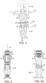
- Assembled tool 20 is shown in front view in Fig. 2 , in side view in Fig. 3 , and in vertical cross section in Fig. 4 .
- Fig. 4 some elements in the other Figures are absent, for clarity.
- the tool is described in terms of its orientation in the pictures of the Figures, but terms such as top, bottom, lower, etc. shall not be limiting since it will understood the tool may be used of stored in any orientation.
- the tool embodiment 20 is comprised of opposing side housings 22, 24 that are preferably made of a strong thermoset plastic, optionally a metal alloy or a carbon fiber epoxy composite.
- each housing has (a) an upper end called the pivot end which has a pivot hole 66C, 66D respectively that is centered on transverse axis 52; (b) a mid-boy portion, (c) a lower end comprised of spaced apart forks 54C, 54D respectively that define between them a U shape opening 65; and (d) a central portion with a through hole 61C, 61D respectively that is centered on transverse axis 50; and (d) a locking pin hole 67C, 67D respectively that is centered on transverse axis 48 which axis runs through the mid-body portion of the housing.
- the axes 48, 50, 52 are parallel to each other and intersect vertical axis CL of tool 20 when the tool is assembled.
- the housings are nearly mirror-identical, but for optional parts such as shield portions, any reciprocal male-female portions, and features that might be associated with a locking mechanism, such as described below.
- the arms, described next, have mirror shapes.
- Sometimes reference herein is made to a feature having a number that lacks a suffix letter. Such should be construed as a reference to all features which have the same number with a suffix letter.
- Arms 26, 28, which are also shown in Fig. 5 and 6 have mirror shapes.
- Each arm, as exemplified by Fig. 5 and arm 26, has an upper pivot end 33A where is the aforementioned pivot hole, a descending shank 35A that connects to a C shape portion 37A, at the bottom of which is the lower terminal end and jaw 42A.
- Each arm has a tab 44A, 44B respectively which descends from the bottom of the shank and is a portion of that which defines the C shape interior concavity of the arm.
- the shank and tabs and nubs mentioned below are features which generally extend in the lengthwise axis direction of the tool.
- the arms are preferably made of a strong steel, preferably a corrosion resisting (stainless) steel, such as AISI type 316 steel or 17-4PH steel.
- a corrosion resisting (stainless) steel such as AISI type 316 steel or 17-4PH steel.
- AISI type 316 steel or 17-4PH steel AISI type 316 steel or 17-4PH steel.
- alternative use may be made of a copper base alloy such as admiralty brass or bronze, or of high-strength engineered plastics and composite materials, including carbon-fiber reinforced plastics.
- each arm has an upper end (the pivot end) having pivot hole 66A, 66B that in the assembly lies along axis 52.
- a pin such as the pin 70 of a shackle 54 shown in phantom in Fig. 3 , can be inserted along axis 52 to keep the upper ends of the four parts 22, 24, 26, 28 aligned in pivotable fashion.
- the motion of the arms in the assembly may also be referred to as "partial-rotation" or "part-rotation.”
- an optional hollow rivet 72 shown in Fig. 1 and Fig. 4A .
- Other pin-like means or fasteners for holding the four principal parts 22, 24, 26, 28 together, may be used.
- use may be made of a threaded bolt, a solid rivet, or a pintle affixed to some other device. While for simplicity a pin or fastener is not shown on axis 52 in some assembly figures here, the presence of a pin should be implied by the artisan/reader.
- one or more of the housing or arms may have an integral transverse portion, such as an integral axle stub to fulfil the aforementioned pin or fastener function.
- the concavities of the arms partially overlap and the curved upper surfaces of the respective jaws 42A, 42B mate with each other in overlapping fashion, to provide a curved surface which defines the lower bound of space 68, which space is between the arms and is where an object such as handle 60 will be held during use of the tool 20.
- Tool 20 also has a locking mechanism comprised of locking pin holes 67A, 67B respectively in arms 26, 28.
- the locking pin holes lie along axis 48 and align with housing pin holes 67C, 67D, thus enabling pin 36 to be inserted, thereby holding the arms in the home position, as suggested/shown by Fig. 2 and Fig. 3 .
- Fig. 8 and Fig. 9 show another configuration of locking mechanism, as discussed below.
- a user can with one hand grasp the tool 20 and squeeze the arms 26, 28 above the vertical mid-point of the tool where the outer edges of the arms extend laterally from the opposing side housings.
- the user optionally can squeeze the arms to open the jaws sufficiently to allow them to close around an object such as handle 60 without the user applying the thrusting force associated with the aforementioned "stabbing.”
- Fig. 4A is a side view like Fig. 4 , with partial cross sectioning, showing device 20A which is like device 20 except for having a hollow rivet 72 as fastener at axis 52 to hold the housings together, and having a hollow rivet 74 at axis 50, which keeps in place spacer 30.
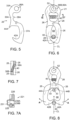
- Fig. 6 is a view of an assembly 21 that comprises arms 26, 28 in their home positions with the housings not pictured, for clarity.
- Fig. 7 is a horizontal plane cross section looking down along axis CL of the assembly 21.
- Fig. 6 and Fig. 7 (and Fig. 1 ) show compression coil spring 40 that is captured by the integral pins 38A, 38B respectively and is captured within the space between the arms. Spring 40 pushes on the arms so that jaws 42A, 42B move toward each other. With reference to Fig. 7 , the length of spring 40 runs at an angle to the plane between the mated arms. When the jaws are in their home position, the terminal or pointed top end of each jaw presses against the interior surface of one of the forks of a housing.
- coil spring 40 is one of several spring force means which may be used, for applying pivoting force to the arms, to cause their jaws to move apart from each other. be used.
- spring force may be applied to the arms by one or more torsion springs which circumscribe axis 52, for instance running around a solid or hollow pin or rivet that runs through holes 66A, 66B.
- one or more leaf springs may be used in to apply the desired pivoting force to the arms; for example a V shape leaf spring may replace the coil spring.
- Other known resilient devices may be used in substitution of coil spring 40 or for the other kinds of springs. For example, rubber or elastic polymer springs may be used.
- One or more than one spring means may be used cooperatively in a device.
- the lower/terminal end surfaces of the jaws may be nominally perpendicular to the length of the tool, or as shown in Fig. 2 , preferably curved so that when the jaws are in the home position, the lower end of the tool comprises a (curved) V shape contour surface 70.
- Fig. 8 is a side view like Fig. 6 , showing how, when tool 20 is forced (stabbed) against an object 60 (as shown by the arrow along the CL axis), contact of the object the V shape curved surface 70 thrusts the jaws 42A, 42B outwardly and away from each other as indicated by arrows A.
- a user may squeeze the arms toward each other in proximity to the coil spring location, thereby to open the jaws and engage an object. That may be useful where the object being engaged is non-rigid, such as a cable or a rope which is not taut, etc.
- Fig. 8 also illustrates how the extent of opening (outward motion) of the arms will be desirably limited, due to engagement of tabs 44A and 44B of the respective arms with bushing 30 which lies along axis 50.
- the spacer and forks comprise a preferred feature combination. As illustrated by the Fig. 1 exploded view along with Fig. 2 and Fig. 3 , spacer 30 is held in place along axis 50 by screw 32 and nut 34 which act both as fastener and as a shaft running through the spacer.
- spacer 50 may be mounted on one only of the housings; and, the spacer may comprise an integral feature projecting from one or both of the housing inward facing surfaces.
- the arm-limiting-function of a fastener or a fastener with surrounding spacer there is no appreciable difference and a claim reference to one shall comprise a reference to the other.
- Fig. 2 , 3 , and 6 illustrate how locking pin 36 may optionally be used to keep the arms (and thus the jaws) from opening when they are in their home position. Use of the locking pin can help prevent inadvertent release of an engaged object such as handle 60.
- Tool 221 is an embodiment comprised of arms held together by a fastener at axis 52; there are no housing parts. Tool 221 has features for limiting the closing and opening of the jaws to an extent comparable to that described for tool 20 where the limiting is achieved by using portions of the tool that are associated with the housings.
- Fig. 7A is a cross section like Fig. 7 , showing a portion of tool 221.
- Tool 221 is largely configured like tool 21 of Fig. 6 and comprises arms 226, 228 that are like arms 26, 28. The spring of tool 221 is omitted for clarity of illustration.
- Tool 221 comprises features which act as stop means and thereby limit the relative arm motion and associated relative jaws opening. More specifically, arm 226 has integral pin 238A which has a laterally projecting portion that is hit by integral pin 238B of arm 228 when arm 228 moves sufficiently close, thereby limiting jaw opening.
- tool 221 comprises changeable length linking means, connecting the arms.
- arm 228 is connected to arm 226 by lanyard 231, thereby limiting the separation distance of the arms and the of related jaw closing.
- Other linkages of equivalent function may be used in substitution of a lanyard.
- use may be made a slotted rigid link that extends pivotably from one arm to a pin on the other arm, with the pin within the slot.
- Tool 221 may further comprise a pair of housings, not shown, having pivot ends and pivot holes lying along the pivot axis, between which the mated arms 226, 227 are contained.
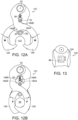
- Fig. 11 is an exploded view of portions of an alternate embodiment device 120 which is much like the device 20 shown in Fig. 2 , but which has a different locking mechanism.
- Fig. 12A and Fig. 12B are side views of the device shown in Fig. 11 , illustrating respectively how the device opens to receive an article and how the device closes and locks. Parts which correspond to those of Fig. 1 and other illustrations of device 20 have the same last two digits.
- housings 122, 124 capture arms 126, 128 by means of a not-shown fastener passing through the housing and arm holes on axis 50.
- Spacer 184 is interposed between the housing on axis 52, and a not-shown fastener may run within spacer.
- device 120 has a locking mechanism which comprises bar 76 that is guided for vertical CL axis motion (indicated by an arrow in Fig. 12B ) by fitting in slots 78 in the opposing side housings. Bar 76 is urged downwardly along the slot lengths by spring 80. Bar 76 preferably has a round end, shaped to press-fit receive rectangular shape button 86, to make it easier for a user to move the bar vertically against the spring bias.
- Each arm has a first nub, 182A, 182B respectively on the upper surface of the curved C shape portion, near the shank that runs to the pivot end; and each arm has a second nub 188A, 188B respectively, on the shank.
- Fig. 13 is a partial side view of tool 120 showing button 86 and, by the arrow. its vertical motion which moves bar 76. Latching means, to hold button 86 in a particular position may be provided.
- a slide button 86 may be present on both ends of the locking bar 76, pressed of screw-fastened onto the end of the bar.
- an embodiment of button 80 will have, on its left-right sides, molded resilient latch portions (e.g., small protrusions) that fit into detents in the edge of the housing depression that holds the button against the spring force, when the button is in uppermost position, as shown. (The latches and detents are not shown but are within ready comprehension of the artisan.)
- buttons 12B automatically locking the arms, so the object desirably cannot be removed from space 68 without manual intervention, to move the button, then to press inwardly on the shanks of the arms.
- the button configuration and means of latching may be carried out in different ways within the scope of invention.
- the button could be on the exterior of the housing and not in a recess
- the latching feature could be interior of the housing and associated with the bar and not the button.
- Fig. 10 illustrates another feature of the invention which enables engagement and capture of an object even though it is not being stabbed or contacted by relative motion along the central CL axis of tool 20.
- an off-center object 60 will push on the angle-curved terminal surface of arm jaw 42B and cause the jaw to move away from contact with the U shape opening at the lower end of the housing.
- the lower end of each housing comprises forks which have angled tips 56 that help guide tool 20 in engaging off-center object 60.
- the assembly 21 of Fig. 6 is an embodiment which could be utilized for grasping a load, notwithstanding the absence of the opposing side housings, and the resultant absence of features of exemplary tool 20. Modifications might be made to the assembly 21 to compensate for some of those missing features, for example, to limit the travel toward each other of the jaws 42A, 42B.
- a tool of the present invention may be fastened to the arm of a robotic device by means of a pin like pin 70.
- the invention tool fulfils objects of the invention.
- the tool can be engaged with a load by "stabbing" at the engagement point on an object, either manually or mechanically.
- the tool will not disengage when the load applied to an object fluctuates or goes to zero.
- the tool further optionally has a safety lock to inhibit inadvertent release of a load.
- the tool is compact and there is little tendency for snagging of a disengaged tool with extraneous objects.
- the tool enables easier one-hand manual engagement or disengagement.
- the tool can be manufactured on an economic mass basis.
Description
- This application claims benefit of provisional
application serial number 62/642,270 filed March 13, 2018 - The present invention relates to tools that are useful for riggers and the like, for connecting lines to objects. In particular the present invention relates to hooks shaped for engaging a rod, bar or line.
- Sister hooks, normally comprising mated hook-pairs, are well known devices for connecting a line, such as a metal cable or rope, to an object that has a fitting or portion which can be engaged by a J shape hook terminal end. Sister hooks such as those described in
US-550189 , are well known in the prior art. An essential prior art sister hook comprises a pair of J shape hooks, the shanks of which have ring shaped ends through which a rope, cable or ring is passed for pulling on the hooks while at the same time holding them overlappingly mated with each other as a pair. A unique aspect of a sister hook device is that the shank of a first hook portion provides a mousing (closure) for the hook opening of the mating second hook portion of the device. -
GB-2307941 -
US-346811 discloses overlapping jaws with contoured surfaces that forms a V shape contour surface. - So long as the load is maintained, prior art sister hooks provide good self-locking; that is, they will not open to release the load. And sister hooks are relatively easily released when tension on the hook shanks is relieved.
- However, sister hooks may be unreliable when the load applied for lifting or pulling on the hook varies or goes to zero over time, as for instance occurs when the pulled object shakes or the line-force applied to the hooks is momentarily relieved. Prior art sister hooks also can be bulky and prone to snagging extraneous objects when not engaged with a load. And, typically, a rigger must use both hands to engage a pair of sister hooks with an object - the rigger has to hold the hooks in place until a force is applied to the shank of the hook.
- Sister hooks are known useful devices, and their utility can be expanded if the limitations which were just mentioned can be overcome.
- An object of the present invention is to provide a tool which may be engaged with a load by one handed motion. Another object is to reduce the tendency for a sister hook type tool to disengage from the load when the force applied to the load through the hook varies greatly and or goes to zero during time of use. A still further object is to provide a sister hook type tool which manually can be disengaged from (or engaged with) with a load by the use of one hand.
- According to the invention, said and further objects are achieved by a tool for gripping an object as disclosed in claim 1.
- A sister hook embodiment can by engaged with an object by longitudinal thrusting, referred to as "stabbing" the object. During stabbing, force applied to the jaw ends (hook ends) of arms which are spring loaded causes the jaws to open. The spring then causes the jaws to close and to hold in "sister fashion" the object.
- In embodiments of the invention, the arms are captured between opposing side housings and may be locked to inhibit accidental release of the object. The fork shape lower end of each housing, and the lower surface of the jaws comprises angled and V shape contour surfaces, so that even if an object is not stabbed "dead-on", the object will be guided into the end of the tool and thereby will be captured.
- A sister hook type tool embodiment comprises two spaced apart housings between which are sandwiched a pair of mating arms having planar surfaces. Each arm has a pivot end, a shank, and a grip which has a C shape. The arms are pivotably connected to each other and to the housings at upper end pivot locations by such as one of the kinds of fasteners described herein or equivalent, including the pin of a shackle that is acting as a fastener. The C shape of the grip portion of each arm defines an open-sided concavity. The terminal end of each arm grip portion comprises a jaw. Mating concavities of arms define an object holding space when the jaws overlapping close on each other in "sister fashion." Each housing has a fork end which defines a U shape opening. A fastener or spacer within the housing limits the outward rotation of the arms and thus the opening of the jaws.
- The lowermost terminal end surface of each jaw is curved; and the mated jaw surfaces define a V shape surface lower end of the tool, for stabbing engagement of an object when the jaws are in home position. The tips of the forks are sloped to aid the object engagement.
- In embodiments of the invention, a locking mechanism enables locking of the arms in the home position. The locking mechanism may be a pin which is a separate element that is insertable into aligned-mating holes of the arms. Alternatively, the locking mechanism may be a spring loaded bar that runs from a guide feature in one housing to a guide feature in the other housing. When the locking mechanism is released, or if it is not present, manual squeezing of the arms near the mid-point of the tool will open the jaws.
- In other embodiments of the invention, the arms have the configuration, spring and motions described above; they are held to each other at the pivot hole by a fastener or other pinning means. There are no housings and limitation of arm motion, and the related jaw opening and closing are achieved in one respect by a stop feature integral with the arms and in another respect by a spacing limiter such as a lanyard.
- The foregoing and other objects, features and advantages of the present invention will become more apparent from the following description of preferred embodiments and accompanying drawings.
-
-
Fig. 1 is an exploded view of a tool of the present invention, showing essential principal parts which include opposing side housings and mating arms with jaw-lower ends. -
Fig. 2 is a front view of a tool of the present invention, namely, an assembly comprised of the parts shown inFig. 1 . -
Fig. 3 is a right side view of the tool shown inFig. 2 . -
Fig. 4 is a right side cross section view of the tool ofFig. 1 with the locking pin and bushing absent. -
Fig. 4A is a side, partial cross-sectioned, view of a modification of the tool shown inFig. 2 . -
Fig. 5 is front view of one of the two arms of the tool ofFig. 2 . -
Fig. 6 is a front view of the first arm ofFig. 5 as it mates with a mirror-like second arm, along with a compression spring to thereby hold a rod. A pin in theholes -
Fig. 7 is a horizontal plane cross section of the assembly ofFig. 6 , looking along vertical axis CL, showing how the spring runs at an angle to the plane between the arms. -
Fig. 7A is a cross section like that ofFig. 7 , shown an embodiment of tool which lacks housings. -
Fig. 8 is a front view likeFig. 6 , showing the arms of a sister hook tool and the jaws as they are separated from each other while engaging an object with relative longitudinal axis motion. -
Fig. 9 illustrates a prior art generic object having a handle which can be engaged for lifting by a sister hook of the present invention. -
Fig. 10 is a partial front view of the lower end of a sister hook of the present invention, like the view ofFig. 2 , showing the lower end of the sister hook as it is being pushed (stabbed) toward an off-center object to engage it. -
Fig. 11 is an exploded view of portions of an alternate embodiment tool, like the tool shown inFig. 2 , but having a different locking mechanism. -
Fig. 12A and Fig. 12B are side views of the tool shown inFig. 11 , illustrating respectively how the tool opens to receive an article and how the device closes and locks. -
Fig. 13 is a partial side view of a tool like that shown inFig. 11 , with a locking button. - The present invention tool/device is said to be capable of being "stab connectable" to an object, then to hold it in sister-hook fashion. By that jargon is meant that the device can be thrust toward an object such as the bar shape handle 60 of a fitting 62, which for example is secured to a
stationary object 64, as shown inFig. 9 asassembly 55. As a result of such "stabbing" the jaws of the invention sister hook will become engaged with the object, for lifting or pulling of the object. -
Fig. 1 is an exploded view of device 20 (also called here tool 20), an embodiment of the present invention.Assembled tool 20 is shown in front view inFig. 2 , in side view inFig. 3 , and in vertical cross section inFig. 4 . InFig. 4 some elements in the other Figures are absent, for clarity. The tool is described in terms of its orientation in the pictures of the Figures, but terms such as top, bottom, lower, etc. shall not be limiting since it will understood the tool may be used of stored in any orientation. - The
tool embodiment 20 is comprised of opposingside housings Fig. 1 , each housing has (a) an upper end called the pivot end which has apivot hole transverse axis 52; (b) a mid-boy portion, (c) a lower end comprised of spaced apartforks 54C, 54D respectively that define between them a U shape opening 65; and (d) a central portion with a throughhole transverse axis 50; and (d) alocking pin hole transverse axis 48 which axis runs through the mid-body portion of the housing. Theaxes tool 20 when the tool is assembled. - The housings are nearly mirror-identical, but for optional parts such as shield portions, any reciprocal male-female portions, and features that might be associated with a locking mechanism, such as described below. The arms, described next, have mirror shapes. Sometimes reference herein is made to a feature having a number that lacks a suffix letter. Such should be construed as a reference to all features which have the same number with a suffix letter.
-
Arms Fig. 5 and 6 , have mirror shapes. Each arm, as exemplified byFig. 5 andarm 26, has an upper pivot end 33A where is the aforementioned pivot hole, a descendingshank 35A that connects to aC shape portion 37A, at the bottom of which is the lower terminal end andjaw 42A. Each arm has atab - The arms are preferably made of a strong steel, preferably a corrosion resisting (stainless) steel, such as AISI type 316 steel or 17-4PH steel. Optionally, alternative use may be made of a copper base alloy such as admiralty brass or bronze, or of high-strength engineered plastics and composite materials, including carbon-fiber reinforced plastics.
- In the assembled tool,
spacer 84 andspacer 30 help space the housings relative to each other, for good cooperation with the arms.Arms tool 20 mate with holes in the housings. As best shown inFig 1 , each arm has an upper end (the pivot end) having pivot hole 66A, 66B that in the assembly lies alongaxis 52. Thus, a pin, such as thepin 70 of ashackle 54 shown in phantom inFig. 3 , can be inserted alongaxis 52 to keep the upper ends of the fourparts - Alternatively, use may be made of an optional
hollow rivet 72, shown inFig. 1 andFig. 4A . Other pin-like means or fasteners, for holding the fourprincipal parts axis 52 in some assembly figures here, the presence of a pin should be implied by the artisan/reader. In still other embodiments one or more of the housing or arms may have an integral transverse portion, such as an integral axle stub to fulfil the aforementioned pin or fastener function. - When the
arms Fig. 2 , the concavities of the arms partially overlap and the curved upper surfaces of therespective jaws space 68, which space is between the arms and is where an object such ashandle 60 will be held during use of thetool 20. -
Tool 20 also has a locking mechanism comprised of lockingpin holes arms axis 48 and align with housing pin holes 67C, 67D, thus enablingpin 36 to be inserted, thereby holding the arms in the home position, as suggested/shown byFig. 2 andFig. 3 . In other embodiments there is no locking pin;tool 20 nonetheless will be functional, since holding an object which is exerting sufficient lengthwise CL axis force will prevent the arm jaws from opening. SeeFig. 6. Fig. 8 andFig. 9 show another configuration of locking mechanism, as discussed below. - With reference to
Fig. 2 , a user can with one hand grasp thetool 20 and squeeze thearms handle 60 without the user applying the thrusting force associated with the aforementioned "stabbing." -
Fig. 4A is a side view likeFig. 4 , with partial cross sectioning, showingdevice 20A which is likedevice 20 except for having ahollow rivet 72 as fastener ataxis 52 to hold the housings together, and having ahollow rivet 74 ataxis 50, which keeps inplace spacer 30. -
Fig. 6 is a view of anassembly 21 that comprisesarms Fig. 7 is a horizontal plane cross section looking down along axis CL of theassembly 21.Fig. 6 and Fig. 7 (andFig. 1 ) showcompression coil spring 40 that is captured by theintegral pins Spring 40 pushes on the arms so thatjaws Fig. 7 , the length ofspring 40 runs at an angle to the plane between the mated arms. When the jaws are in their home position, the terminal or pointed top end of each jaw presses against the interior surface of one of the forks of a housing. Generally,coil spring 40 is one of several spring force means which may be used, for applying pivoting force to the arms, to cause their jaws to move apart from each other. be used. In a variation of spring means, not shown but within ordinary skill, spring force may be applied to the arms by one or more torsion springs which circumscribeaxis 52, for instance running around a solid or hollow pin or rivet that runs throughholes coil spring 40 or for the other kinds of springs. For example, rubber or elastic polymer springs may be used. One or more than one spring means may be used cooperatively in a device. - The lower/terminal end surfaces of the jaws may be nominally perpendicular to the length of the tool, or as shown in
Fig. 2 , preferably curved so that when the jaws are in the home position, the lower end of the tool comprises a (curved) Vshape contour surface 70. Such end shape helps the user engage the tool with an object.Fig. 8 is a side view likeFig. 6 , showing how, whentool 20 is forced (stabbed) against an object 60 (as shown by the arrow along the CL axis), contact of the object the V shape curvedsurface 70 thrusts thejaws -
Fig. 8 also illustrates how the extent of opening (outward motion) of the arms will be desirably limited, due to engagement oftabs bushing 30 which lies alongaxis 50. The spacer and forks comprise a preferred feature combination. As illustrated by theFig. 1 exploded view along withFig. 2 andFig. 3 ,spacer 30 is held in place alongaxis 50 byscrew 32 andnut 34 which act both as fastener and as a shaft running through the spacer. - Alternatively, other means for mounting
spacer 50 may be used, including a solid or hollow rivet, or some other sort of shaft. In other alternatives: the spacer may be mounted on one only of the housings; and, the spacer may comprise an integral feature projecting from one or both of the housing inward facing surfaces. In terms of the arm-limiting-function of a fastener or a fastener with surrounding spacer, there is no appreciable difference and a claim reference to one shall comprise a reference to the other. -
Fig. 2 ,3 , and6 illustrate how lockingpin 36 may optionally be used to keep the arms (and thus the jaws) from opening when they are in their home position. Use of the locking pin can help prevent inadvertent release of an engaged object such ashandle 60. -
Tool 221 is an embodiment comprised of arms held together by a fastener ataxis 52; there are no housing parts.Tool 221 has features for limiting the closing and opening of the jaws to an extent comparable to that described fortool 20 where the limiting is achieved by using portions of the tool that are associated with the housings. -
Fig. 7A is a cross section likeFig. 7 , showing a portion oftool 221.Tool 221 is largely configured liketool 21 ofFig. 6 and comprisesarms arms tool 221 is omitted for clarity of illustration.Tool 221 comprises features which act as stop means and thereby limit the relative arm motion and associated relative jaws opening. More specifically,arm 226 hasintegral pin 238A which has a laterally projecting portion that is hit byintegral pin 238B ofarm 228 whenarm 228 moves sufficiently close, thereby limiting jaw opening. Andtool 221 comprises changeable length linking means, connecting the arms. More specifically,arm 228 is connected to arm 226 bylanyard 231, thereby limiting the separation distance of the arms and the of related jaw closing. Other linkages of equivalent function may be used in substitution of a lanyard. For example, use may be made a slotted rigid link that extends pivotably from one arm to a pin on the other arm, with the pin within the slot.Tool 221 may further comprise a pair of housings, not shown, having pivot ends and pivot holes lying along the pivot axis, between which the matedarms 226, 227 are contained. -
Fig. 11 is an exploded view of portions of analternate embodiment device 120 which is much like thedevice 20 shown inFig. 2 , but which has a different locking mechanism.Fig. 12A and Fig. 12B are side views of the device shown inFig. 11 , illustrating respectively how the device opens to receive an article and how the device closes and locks. Parts which correspond to those ofFig. 1 and other illustrations ofdevice 20 have the same last two digits. Referring to the severalFigures showing device 120,housings capture arms axis 50.Spacer 184 is interposed between the housing onaxis 52, and a not-shown fastener may run within spacer. - Instead of a locking mechanism which comprises a pin that fits into aligned holes, for locking the arms the home position,
device 120 has a locking mechanism which comprisesbar 76 that is guided for vertical CL axis motion (indicated by an arrow inFig. 12B ) by fitting inslots 78 in the opposing side housings.Bar 76 is urged downwardly along the slot lengths byspring 80.Bar 76 preferably has a round end, shaped to press-fit receiverectangular shape button 86, to make it easier for a user to move the bar vertically against the spring bias. Each arm has a first nub, 182A, 182B respectively on the upper surface of the curved C shape portion, near the shank that runs to the pivot end; and each arm has asecond nub - As illustrated by comparing
Fig. 12A and Fig. 12B , when the jaws oftool 120 are maximally opened, their spacing is determined by contact oftabs spacer 130, similar to howtool 20 works. Thus from the full open position, the jaws can only move inwardly as indicated by arrows M. When the arms are moved inwardly and the jaws come to their home position, thereafter the jaws can only more outwardly as indicated by arrows P inFig. 12B . At the home position, the bias ofspring 80 moves the bar downwardly, so that the motions P are prevented becausefirst nubs Fig. 12B . If a user then raises the bar, that allows the first nubs to move left-right, allowing the jaws to open. In an alternate embodiment, there is no spring and the bar is moved manually to lock and unlock the arms and jaws. -
Fig. 13 is a partial side view oftool 120showing button 86 and, by the arrow. its vertical motion which movesbar 76. Latching means, to holdbutton 86 in a particular position may be provided. - A
slide button 86 may be present on both ends of the lockingbar 76, pressed of screw-fastened onto the end of the bar. With reference toFig. 13 , an embodiment ofbutton 80 will have, on its left-right sides, molded resilient latch portions (e.g., small protrusions) that fit into detents in the edge of the housing depression that holds the button against the spring force, when the button is in uppermost position, as shown. (The latches and detents are not shown but are within ready comprehension of the artisan.) - The engagement of the latches with the housing will keep the button, and thus the
bar 76, in the upmost or "unlock" position, with the spring compressed. When the bar is released, as by a user pressing the button(s) downward with force sufficient to overcome the detent engagement, the spring then urges the button to lock the arms, because the bar engages first nubs 182, as already described. SeeFig. 12B . - When an object is "stabbed" to engage it, provided the button/bar are in upward position (where the button will be held manually or by the latches just described), the force from contact with the object causes either or both of the jaws to move outwardly. That action pivots the arms so the shank portions come closer to each other. See
Fig. 12A . When the shank portions sufficiently move toward each other and the centerline of the tool, as shown inFig. 12A one or both second nubs 188 contacts bar 76, pushing it downwardly with sufficient force to pull the button(s) free of latch engagement with the housing. Then, the spring urges thebar 76 down until it engages the space between first nubs 182, as shown inFig. 12B , automatically locking the arms, so the object desirably cannot be removed fromspace 68 without manual intervention, to move the button, then to press inwardly on the shanks of the arms. The button configuration and means of latching may be carried out in different ways within the scope of invention. For example, the button could be on the exterior of the housing and not in a recess, and the latching feature could be interior of the housing and associated with the bar and not the button. -
Fig. 10 illustrates another feature of the invention which enables engagement and capture of an object even though it is not being stabbed or contacted by relative motion along the central CL axis oftool 20. As suggested byFig. 10 , an off-center object 60 will push on the angle-curved terminal surface ofarm jaw 42B and cause the jaw to move away from contact with the U shape opening at the lower end of the housing. In addition, the lower end of each housing comprises forks which have angledtips 56 that help guidetool 20 in engaging off-center object 60. - It will be appreciated that the
assembly 21 ofFig. 6 is an embodiment which could be utilized for grasping a load, notwithstanding the absence of the opposing side housings, and the resultant absence of features ofexemplary tool 20. Modifications might be made to theassembly 21 to compensate for some of those missing features, for example, to limit the travel toward each other of thejaws - While the invention has been described in terms of a user grasping the sister hook tool manually, the invention may attached to mechanical members and machine controlled, and used in other ways where there is absence of manual contact. For example, a tool of the present invention may be fastened to the arm of a robotic device by means of a pin like
pin 70. - Thus the invention tool fulfils objects of the invention. The tool can be engaged with a load by "stabbing" at the engagement point on an object, either manually or mechanically. The tool will not disengage when the load applied to an object fluctuates or goes to zero. The tool further optionally has a safety lock to inhibit inadvertent release of a load. The tool is compact and there is little tendency for snagging of a disengaged tool with extraneous objects. The tool enables easier one-hand manual engagement or disengagement. The tool can be manufactured on an economic mass basis.
- The invention, with explicit and implicit variations and advantages, has been described and illustrated with respect to several embodiments. Those embodiments should be considered illustrative and not restrictive. Any use of words such as "optional" and "preferred" and variations suggest a feature or combination which is desirable but which is not necessarily mandatory. Thus embodiments lacking any such preferred feature or combination may be within the scope of the claims which follow.
Claims (15)
- A tool (20) for gripping an object (60), having a lengthwise center axis and, running perpendicular thereto, a pivot axis (52), and a stop axis (50), the tool comprising:a first arm (26);a second arm (28), abutting the first arm (26);each arm (26, 28) having in the lengthwise axis direction a pivot end and a shank connected to the pivot end, and a grip end connected to the shank, the grip end comprising a jaw (42A, 42B) that is at a terminal end of the arm, the grip end C shaped and defining a concavity which is open- sided, wherein each arm pivot end is configured for pivot motion about said pivot axis (52), enabling the arm (26, 28) to pivot from an arm home position to an arm open position;wherein at said home position the jaw (42A) and concavity of one arm respectively overlap the jaw (42B) and concavity of the other arm, and mated concavities thereby define a space within which said object (60) may be gripped;wherein when the jaws (42A, 42B) are in said open position the jaws are spaced apart sufficiently to allow the object (60) to enter said overlapping concavity space;at least one spring (40) for urging said arms to the home position;a first housing (22);a second housing (24) spaced apart from the first housing (22) and connected to the first housing by a fastener (32,74) running along said stop axis;wherein said arms (26, 28) are pivotably and slidably contained in the space between the housings (22, 24);wherein a portion of the shank of each arm (26, 28) extends laterally from said space between the housings, to enable manual pressing on the arm to move the arm in the direction of said open position, against the force of said spring (40);each housing (22, 24) having in the lengthwise axis direction a first end positioned along said pivot axis, a mid-body, and a second end;the second end comprising a pair of forks (54) defining a U shape opening (65) which aligns with said overlapping concavity space when the arms are in the home position;each fork (54) having a tip; characterized in thatthe tool (20) has a locking axis and each arm has a tab (44A, 44B) extending lengthwise from said shank into the concavity of said C shape grip end; and the pivot motion of each arm (26,28) during opening of the jaws (42A, 42B) is limited by contact of the tab (44A, 44B) with a fastener (32, 34) or a spacer (30, 130) positioned around the fastener (32, 34).
- The tool (20) of claim 1 characterized in that the fastener (32, 34) running between the housings (22, 24) along the stop axis (50), wherein the tab (44A, 44B) of each arm extends from the grip section in a generally lengthwise direction away from the pivot end for contacting said fastener (32, 34) or said spacer (30, 130) and limiting the extent of arm pivot motion at said arm open position.
- The tool (20) of claim 1, characterized in that each arm (26, 28) has a mirror-shape of the other arm and each housing has a similar external shape.
- The tool (20) of claim 1, characterized by comprising a pin (70), hollow rivet (72), or further fastener running through holes in the pivot end of each arm and the first end of each housing.
- The tool (20) of claim 1, characterized in that arms (26, 28) in home position have overlapping jaws with contoured surfaces that form a V shape contour surface (70) facing in the direction of said terminal end of the tool.
- The tool (20) of claim 1, characterized in that the tip of each fork (54) has a surface which is angled relative to the central length axis, to guide any said object contacted by the tool terminal end into the U shape opening (65) of the fork pair.
- The tool (20) of claim 1, characterized in that each housing has a hole (67C, 67D) aligned with the locking axis (48), and the shank of each arm has a hole (67A, 67B) that is aligned with the locking axis when the arms (26, 28) are in home position; further comprising a removable pin (36) running along the locking axis and passing through all said holes.
- The tool (20) of claim 1, characterized by comprising:a first nub (182A, 182B) on the grip part of each arm near the shank, the first nub projecting generally in the lengthwise direction toward the pivot end of the arm; and,a locking bar (76) running transverse to the length of the tool and between lengthwise slots (78) in the opposing side housings, the locking bar (76) movably positionable in the tool lengthwise direction for selectively engaging the first nub (182A,182B) of each arm and thereby locking the movement of the arms when the arms are in the home position.
- The tool (20) of any one of the preceding claims, characterized by comprising at least one button (86) connected to the end of the locking bar (76), the at least one button (86) being configured for latching engagement with the housing when in closest proximity position to a pivot end of a housing.
- The tool (20) of any one of the preceding claims, characterized by comprising a second nub (188A, 188B) projecting laterally toward the centerline of the tool for a shank of each arm at an elevation nearer to the pivot end than is the lock bar (76) when each arm is in home position, each second nub (188A, 188B) configured to contact the locking bar when the arms approach open position, and thereby move the locking bar (76) away from the pivot ends of the housings.
- The tool (20) of claim 1, characterized in that each arm has an integral pin (38A, 38B) on the shank portion, each pin (38A, 38B) extending generally in a direction transverse to said length axis, and wherein said spring (40) runs between said pins.
- The tool (20) of claim 1, characterized in that each arm has a nub (188A, 188B) extending from the C shape section in the general direction of the arm pivot end, further comprising:
a movable locking bar (76) running between the housings; each end of the locking bar guided for lateral motion of the locking bar (76) along the central lengthwise axis of the tool by a feature of at each housing, wherein the locking bar is resiliently biased in the direction of the U shape housing openings (62); and wherein engagement of the nubs with the locking bar (72) keeps the arms in the home position; and wherein manual movement of the locking bar against the spring (80) bias enables the arms to more to the open position. - The tool of any one of the preceding claims, characterized in that the shank of each arm has a hole (67A, 67B) that is aligned with the locking axis (48) when the arms are in home position; further comprising a removable pin (36) running along the locking axis and passing through said aligned holes (67A, 67B).
- The tool of any one of the preceding claims, characterized in that the first arm (26) and the second arm (28) are contained between the housings (22, 24).
- A method of engaging a tool with an object (60) which comprises:providing a tool (20) according to any of the preceding claims, with the arms (26, 28) in the home position;thrusting the tool (20) at a said object (60) so the terminal end of the tool and contour surface of the jaws (42A, 42B) contacts the object with sufficient force to cause each arm (26, 28) to pivot about the arm pivot end, thereby causing the jaws (42A, 42B) to separate and allowing the object to enter said mated concavity space; and, allowing the spring (40) to cause the arms (26, 28) to return to the home position.
Applications Claiming Priority (2)
| Application Number | Priority Date | Filing Date | Title |
|---|---|---|---|
| US201862642270P | 2018-03-13 | 2018-03-13 | |
| PCT/IB2019/000233 WO2019175659A1 (en) | 2018-03-13 | 2019-03-13 | Stab-connectable sister hook |
Publications (4)
| Publication Number | Publication Date |
|---|---|
| EP3765754A1 EP3765754A1 (en) | 2021-01-20 |
| EP3765754A4 EP3765754A4 (en) | 2021-12-01 |
| EP3765754B1 true EP3765754B1 (en) | 2024-01-10 |
| EP3765754C0 EP3765754C0 (en) | 2024-01-10 |
Family
ID=67903914
Family Applications (1)
| Application Number | Title | Priority Date | Filing Date |
|---|---|---|---|
| EP19767091.2A Active EP3765754B1 (en) | 2018-03-13 | 2019-03-13 | Stab-connectable sister hook |
Country Status (6)
| Country | Link |
|---|---|
| US (1) | US11125266B2 (en) |
| EP (1) | EP3765754B1 (en) |
| CN (1) | CN112105827B (en) |
| AU (1) | AU2019235524A1 (en) |
| CA (1) | CA3093629C (en) |
| WO (1) | WO2019175659A1 (en) |
Families Citing this family (2)
| Publication number | Priority date | Publication date | Assignee | Title |
|---|---|---|---|---|
| US11293479B2 (en) * | 2019-05-21 | 2022-04-05 | Bowerbags Llc | Modular clipping system |
| US11926507B1 (en) | 2021-08-18 | 2024-03-12 | The United States Of America As Represented By The Secretary Of The Navy | Modular unmanned line/tool emplacement (MULE) hook |
Family Cites Families (17)
| Publication number | Priority date | Publication date | Assignee | Title |
|---|---|---|---|---|
| US550189A (en) * | 1895-11-19 | Harness snap-hook | ||
| US346811A (en) | 1886-08-03 | Teeeitoey | ||
| GB189826923A (en) * | 1898-12-20 | 1899-10-28 | David Thomas Young | Improvements in Hooks for Cranes and other Lifting Machinery and Appliances. |
| US1668325A (en) * | 1928-01-10 | 1928-05-01 | Kreutz Carl | Safety hook for tire chains |
| CH130226A (en) * | 1928-02-28 | 1928-11-30 | Francois Planque | Carabiner holder. |
| GB316761A (en) | 1928-07-20 | 1929-08-08 | Clayton Aniline Co Ltd | Manufacture of a condensation product of ª‡-naphthylamine and acetaldehyde and the application thereof in the manufacture of vulcanised rubber |
| GB316767A (en) * | 1928-07-26 | 1929-08-08 | Bengtsson Svante | Improvements relating to detachable links for harness and the like |
| US2234853A (en) * | 1940-04-24 | 1941-03-11 | John T Brueggeman | Snap hook |
| JPH0866294A (en) * | 1994-08-31 | 1996-03-12 | Okuda Seisakusho:Kk | Hanger hook |
| AP842A (en) * | 1995-12-04 | 2000-06-06 | Bellambie Mining And Industrial Ltd | Safety detaching hooks. |
| ITMI981697A1 (en) | 1998-07-22 | 2000-01-22 | Kong Spa | SNAP CLOSURE CONNECTOR |
| US6463640B1 (en) | 2000-01-13 | 2002-10-15 | Douglas J. Toth | Strap connecting buckle |
| TW517792U (en) * | 2001-05-04 | 2003-01-11 | Chung Shan Inst Of Science | Fast detaching hook |
| JP4056003B2 (en) * | 2003-08-07 | 2008-03-05 | 昭八 和久田 | One-hand clip for preventing the suspended object from falling |
| FR2903395B1 (en) * | 2006-07-04 | 2009-04-17 | C2E Entpr | LIFTING HOOK WITH REMOTE CONTROL AUTONOMOUS IN ENERGY |
| US9488203B2 (en) | 2014-03-05 | 2016-11-08 | Enginuity Inc. | Disconnectable subsea connector |
| US10004926B2 (en) * | 2016-10-18 | 2018-06-26 | Meyer Ostrobrod | Remote overhead anchor |
-
2019
- 2019-03-13 US US16/352,635 patent/US11125266B2/en active Active
- 2019-03-13 CA CA3093629A patent/CA3093629C/en active Active
- 2019-03-13 EP EP19767091.2A patent/EP3765754B1/en active Active
- 2019-03-13 AU AU2019235524A patent/AU2019235524A1/en active Pending
- 2019-03-13 WO PCT/IB2019/000233 patent/WO2019175659A1/en unknown
- 2019-03-13 CN CN201980019220.XA patent/CN112105827B/en active Active
Also Published As
| Publication number | Publication date |
|---|---|
| CN112105827B (en) | 2022-09-16 |
| EP3765754A4 (en) | 2021-12-01 |
| US11125266B2 (en) | 2021-09-21 |
| CA3093629C (en) | 2024-01-02 |
| AU2019235524A1 (en) | 2020-10-15 |
| WO2019175659A1 (en) | 2019-09-19 |
| CA3093629A1 (en) | 2019-09-19 |
| EP3765754C0 (en) | 2024-01-10 |
| CN112105827A (en) | 2020-12-18 |
| US20190285110A1 (en) | 2019-09-19 |
| EP3765754A1 (en) | 2021-01-20 |
Similar Documents
| Publication | Publication Date | Title |
|---|---|---|
| EP3765754B1 (en) | Stab-connectable sister hook | |
| EP3426870B1 (en) | High offset hook latch | |
| EP2620258B1 (en) | Locking pliers with handle locking mechanism | |
| EP1591204B1 (en) | Hand actuable locking clamp | |
| US9844857B2 (en) | Locking pliers with handle locking mechanism | |
| EP1050255A2 (en) | Gravity lockable tongs | |
| US8756771B1 (en) | Locking clip assembly | |
| EP1967324A2 (en) | Universal locking mechanism for a clamp | |
| US7213848B2 (en) | Spring open latch clamp | |
| US10179394B2 (en) | Toggle clamp with locking mechanism | |
| KR20140138308A (en) | Binder | |
| US10004360B1 (en) | Tongs | |
| EP0061257A1 (en) | Scaffold locking hook | |
| EP3002092B1 (en) | Opening/closing work tool | |
| US4474396A (en) | Wood stove and fireplace log handler | |
| CN219485763U (en) | Knife anvil single hand scissors | |
| EP3566810B1 (en) | Plunger clamp with a lever lock | |
| CN105881256A (en) | Self-locking pincer-type clamping device | |
| DE20119348U1 (en) | Fastening device for a two-wheeler accessory | |
| JPH0711923U (en) | Umbrella sliding wheel stop structure |
Legal Events
| Date | Code | Title | Description |
|---|---|---|---|
| STAA | Information on the status of an ep patent application or granted ep patent |
Free format text: STATUS: THE INTERNATIONAL PUBLICATION HAS BEEN MADE |
|
| PUAI | Public reference made under article 153(3) epc to a published international application that has entered the european phase |
Free format text: ORIGINAL CODE: 0009012 |
|
| STAA | Information on the status of an ep patent application or granted ep patent |
Free format text: STATUS: REQUEST FOR EXAMINATION WAS MADE |
|
| 17P | Request for examination filed |
Effective date: 20201001 |
|
| AK | Designated contracting states |
Kind code of ref document: A1 Designated state(s): AL AT BE BG CH CY CZ DE DK EE ES FI FR GB GR HR HU IE IS IT LI LT LU LV MC MK MT NL NO PL PT RO RS SE SI SK SM TR |
|
| AX | Request for extension of the european patent |
Extension state: BA ME |
|
| RIN1 | Information on inventor provided before grant (corrected) |
Inventor name: GARVEY, BENJAMIN Inventor name: GUINDON, JEAN-MARC Inventor name: MANUGE, LOUIS-PHILLIPE Inventor name: MUSSETT, JONATHAN Inventor name: TROWER, ALASTAIR |
|
| DAV | Request for validation of the european patent (deleted) | ||
| DAX | Request for extension of the european patent (deleted) | ||
| A4 | Supplementary search report drawn up and despatched |
Effective date: 20211102 |
|
| RIC1 | Information provided on ipc code assigned before grant |
Ipc: F16G 11/14 20060101ALI20211026BHEP Ipc: B66C 1/36 20060101ALI20211026BHEP Ipc: B63B 21/00 20060101ALI20211026BHEP Ipc: F16B 45/06 20060101AFI20211026BHEP |
|
| P01 | Opt-out of the competence of the unified patent court (upc) registered |
Effective date: 20230515 |
|
| GRAP | Despatch of communication of intention to grant a patent |
Free format text: ORIGINAL CODE: EPIDOSNIGR1 |
|
| STAA | Information on the status of an ep patent application or granted ep patent |
Free format text: STATUS: GRANT OF PATENT IS INTENDED |
|
| INTG | Intention to grant announced |
Effective date: 20230808 |
|
| GRAS | Grant fee paid |
Free format text: ORIGINAL CODE: EPIDOSNIGR3 |
|
| GRAA | (expected) grant |
Free format text: ORIGINAL CODE: 0009210 |
|
| STAA | Information on the status of an ep patent application or granted ep patent |
Free format text: STATUS: THE PATENT HAS BEEN GRANTED |
|
| AK | Designated contracting states |
Kind code of ref document: B1 Designated state(s): AL AT BE BG CH CY CZ DE DK EE ES FI FR GB GR HR HU IE IS IT LI LT LU LV MC MK MT NL NO PL PT RO RS SE SI SK SM TR |
|
| REG | Reference to a national code |
Ref country code: GB Ref legal event code: FG4D |
|
| REG | Reference to a national code |
Ref country code: CH Ref legal event code: EP |
|
| REG | Reference to a national code |
Ref country code: DE Ref legal event code: R096 Ref document number: 602019044917 Country of ref document: DE |
|
| REG | Reference to a national code |
Ref country code: IE Ref legal event code: FG4D |
|
| RAP4 | Party data changed (patent owner data changed or rights of a patent transferred) |
Owner name: ENGINUITY INC. |
|
| U01 | Request for unitary effect filed |
Effective date: 20240206 |
|
| U07 | Unitary effect registered |
Designated state(s): AT BE BG DE DK EE FI FR IT LT LU LV MT NL PT SE SI Effective date: 20240219 |
|
| P04 | Withdrawal of opt-out of the competence of the unified patent court (upc) registered |
Effective date: 20240214 |
|
| U20 | Renewal fee paid [unitary effect] |
Year of fee payment: 6 Effective date: 20240315 |
|
| PGFP | Annual fee paid to national office [announced via postgrant information from national office to epo] |
Ref country code: GB Payment date: 20240208 Year of fee payment: 6 |