EP3765752B1 - Abnehmbares schutzelement für halterungen, die klimatisierungseinheiten halten - Google Patents
Abnehmbares schutzelement für halterungen, die klimatisierungseinheiten halten Download PDFInfo
- Publication number
- EP3765752B1 EP3765752B1 EP19716983.2A EP19716983A EP3765752B1 EP 3765752 B1 EP3765752 B1 EP 3765752B1 EP 19716983 A EP19716983 A EP 19716983A EP 3765752 B1 EP3765752 B1 EP 3765752B1
- Authority
- EP
- European Patent Office
- Prior art keywords
- covering
- pair
- protection member
- designed
- members
- Prior art date
- Legal status (The legal status is an assumption and is not a legal conclusion. Google has not performed a legal analysis and makes no representation as to the accuracy of the status listed.)
- Active
Links
Images

Classifications
-
- F—MECHANICAL ENGINEERING; LIGHTING; HEATING; WEAPONS; BLASTING
- F16—ENGINEERING ELEMENTS AND UNITS; GENERAL MEASURES FOR PRODUCING AND MAINTAINING EFFECTIVE FUNCTIONING OF MACHINES OR INSTALLATIONS; THERMAL INSULATION IN GENERAL
- F16B—DEVICES FOR FASTENING OR SECURING CONSTRUCTIONAL ELEMENTS OR MACHINE PARTS TOGETHER, e.g. NAILS, BOLTS, CIRCLIPS, CLAMPS, CLIPS OR WEDGES; JOINTS OR JOINTING
- F16B5/00—Joining sheets or plates, e.g. panels, to one another or to strips or bars parallel to them
- F16B5/12—Fastening strips or bars to sheets or plates, e.g. rubber strips, decorative strips for motor vehicles, by means of clips
- F16B5/121—Fastening strips or bars to sheets or plates, e.g. rubber strips, decorative strips for motor vehicles, by means of clips fastened over the edge(s) of the sheet(s) or plate(s)
-
- F—MECHANICAL ENGINEERING; LIGHTING; HEATING; WEAPONS; BLASTING
- F16—ENGINEERING ELEMENTS AND UNITS; GENERAL MEASURES FOR PRODUCING AND MAINTAINING EFFECTIVE FUNCTIONING OF MACHINES OR INSTALLATIONS; THERMAL INSULATION IN GENERAL
- F16B—DEVICES FOR FASTENING OR SECURING CONSTRUCTIONAL ELEMENTS OR MACHINE PARTS TOGETHER, e.g. NAILS, BOLTS, CIRCLIPS, CLAMPS, CLIPS OR WEDGES; JOINTS OR JOINTING
- F16B5/00—Joining sheets or plates, e.g. panels, to one another or to strips or bars parallel to them
- F16B5/12—Fastening strips or bars to sheets or plates, e.g. rubber strips, decorative strips for motor vehicles, by means of clips
-
- F—MECHANICAL ENGINEERING; LIGHTING; HEATING; WEAPONS; BLASTING
- F16—ENGINEERING ELEMENTS AND UNITS; GENERAL MEASURES FOR PRODUCING AND MAINTAINING EFFECTIVE FUNCTIONING OF MACHINES OR INSTALLATIONS; THERMAL INSULATION IN GENERAL
- F16B—DEVICES FOR FASTENING OR SECURING CONSTRUCTIONAL ELEMENTS OR MACHINE PARTS TOGETHER, e.g. NAILS, BOLTS, CIRCLIPS, CLAMPS, CLIPS OR WEDGES; JOINTS OR JOINTING
- F16B5/00—Joining sheets or plates, e.g. panels, to one another or to strips or bars parallel to them
- F16B5/12—Fastening strips or bars to sheets or plates, e.g. rubber strips, decorative strips for motor vehicles, by means of clips
- F16B5/126—Fastening strips or bars to sheets or plates, e.g. rubber strips, decorative strips for motor vehicles, by means of clips at least one of the sheets, plates, bars or strips having integrally formed or integrally connected snap-in-features
-
- F—MECHANICAL ENGINEERING; LIGHTING; HEATING; WEAPONS; BLASTING
- F16—ENGINEERING ELEMENTS AND UNITS; GENERAL MEASURES FOR PRODUCING AND MAINTAINING EFFECTIVE FUNCTIONING OF MACHINES OR INSTALLATIONS; THERMAL INSULATION IN GENERAL
- F16B—DEVICES FOR FASTENING OR SECURING CONSTRUCTIONAL ELEMENTS OR MACHINE PARTS TOGETHER, e.g. NAILS, BOLTS, CIRCLIPS, CLAMPS, CLIPS OR WEDGES; JOINTS OR JOINTING
- F16B5/00—Joining sheets or plates, e.g. panels, to one another or to strips or bars parallel to them
- F16B5/12—Fastening strips or bars to sheets or plates, e.g. rubber strips, decorative strips for motor vehicles, by means of clips
- F16B5/128—Fastening strips or bars to sheets or plates, e.g. rubber strips, decorative strips for motor vehicles, by means of clips a strip with a C-or U-shaped cross section being fastened to a plate such that the fastening means remain invisible, e.g. the fastening being completely enclosed by the strip
-
- F—MECHANICAL ENGINEERING; LIGHTING; HEATING; WEAPONS; BLASTING
- F16—ENGINEERING ELEMENTS AND UNITS; GENERAL MEASURES FOR PRODUCING AND MAINTAINING EFFECTIVE FUNCTIONING OF MACHINES OR INSTALLATIONS; THERMAL INSULATION IN GENERAL
- F16M—FRAMES, CASINGS OR BEDS OF ENGINES, MACHINES OR APPARATUS, NOT SPECIFIC TO ENGINES, MACHINES OR APPARATUS PROVIDED FOR ELSEWHERE; STANDS; SUPPORTS
- F16M13/00—Other supports for positioning apparatus or articles; Means for steadying hand-held apparatus or articles
- F16M13/02—Other supports for positioning apparatus or articles; Means for steadying hand-held apparatus or articles for supporting on, or attaching to, an object, e.g. tree, gate, window-frame, cycle
-
- F—MECHANICAL ENGINEERING; LIGHTING; HEATING; WEAPONS; BLASTING
- F24—HEATING; RANGES; VENTILATING
- F24F—AIR-CONDITIONING; AIR-HUMIDIFICATION; VENTILATION; USE OF AIR CURRENTS FOR SCREENING
- F24F13/00—Details common to, or for air-conditioning, air-humidification, ventilation or use of air currents for screening
- F24F13/32—Supports for air-conditioning, air-humidification or ventilation units
Definitions
- the present invention concerns the technical field of protection covers and the subject of the invention is a removable protection member for brackets configured to support air conditioning units.
- air conditioning systems climatisation, heating
- climatisation, heating generally comprise a unit equipped with a compressor and an electric motor, which is often positioned outside the room that must be heated or cooled.
- the bracket comprises a pair of supports having two sides that substantially define the shape of an "L", wherein one of these sides is intended to be secured to the wall.
- one side of the support projects horizontally from the wall and is configured to allow the feet of the air conditioning unit to be rested and held thereon.
- the air conditioning unit is generally provided with two pairs of feet that extend from its lower surface.
- the supports are secured to the wall at a distance that is substantially equal to the distance that separates the pairs of feet of the air conditioning unit.
- a cross member is provided to strengthen the bracket and the ends of said cross member are joined to the supports.
- the ends of the cross member are joined to the side of the supports that is intended to be secured to the wall.
- the cross member is secured to the wall, too, in such a way as to create, together with the supports, a bearing structure that is capable of supporting the weight of the air conditioning unit, at the same time allowing it to be secured to the wall in a stable manner.
- the members of the bracket are made of an antioxidant material (for example, stainless steel) or are subjected to special surface treatments intended to prevent oxidation.
- the distance that separates the feet of the air-conditioning units may vary according to the size of this device or according to the choices made by the building contractor.
- brackets of different sizes more specifically in these brackets the changing element is the mutual distance that separates the horizontal sides of the supports.
- brackets it is not easy to make a protection member for these brackets, since each type of bracket and each size require a corresponding covering member in a suitable size.
- the present invention intends to overcome the drawbacks described above by providing a removable protection member for brackets configured to support air-conditioning units that is simple and economic to construct.
- the main object of the present invention is to provide a removable protection member suited to protect the support brackets of air conditioning units from weather agents that may promote their corrosion.
- the present invention concerns a removable protection member for the support brackets of air conditioning units.
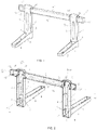
- this protection member hereinafter indicated by the reference numeral 1
- a bracket S made up of at least two supports B, each one of which is substantially “L"-shaped, and at least one straight cross member T designed to connect said supports B.
- the bracket S comprises one pair of supports B having the same size and a single cross member T.
- the upper side B 1 of the supports B is configured to be secured to the wall of a building or to any other bearing wall, generally by means of dowels or similar anchoring systems.
- the support B has also a lower side B 2 that will not be secured to the bearing wall.
- the upper side B 1 and the lower side B 2 can be mutually joined in correspondence with one end, so that the support has substantially the shape of an "L".
- the lower side B 2 projects from the latter in a direction that is substantially orthogonal to it.
- the cross member T is secured to the wall by means of dowels or similar anchoring systems.
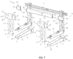
- the removable protection member 1 that is the subject of the present invention comprises at least one pair of first covering members 2 designed to cover the supports Band therefore suited to be substantially "L"-shaped.
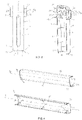
- the first covering members 2 have a side 3 whose cross section substantially has the shape of an open half shell, as shown in Figure 3 .
- the opening 4 made in the half shell-shaped side 3 makes it possible to apply these members 2 to the supports B even when the latter are secured to the bearing wall.
- each first covering member 2 comprises an upper portion 5 and a lower portion 6 that are substantially straight and extend along respective extension directions X 1 , X 2 that are straight, too.
- the upper portion 5 can be positioned on the upper side B 1 of the support, in such a way as to orient the opening 4 towards the wall and make it easier to cover said side B 1 from above with the half shell-shaped side 3.
- the upper portion 5 and the lower portion 6 of the first covering member 2 can be coupled with each other in correspondence with one of their ends 7, 8 and for this purpose fixed joints 9 are also provided, which are associated with said ends 7, 8.
- Both coupling ends 7, 8 of the upper portion 5 and of the lower portion 6 are provided with an open edge 10, 11 and the fixed joints 9 make it possible to promote the removable coupling of said portions 5, 6 in such a way as to angularly space the respective extension directions X 1 , X 2 by approximately 90°.
- the shape of the first covering members 2 will substantially be equal to the geometric "L" shape of the supports B of the bracket S.
- the fixed joints 9 may comprise at least one shaped extension 12 that extends starting from the open edge 10 of the upper portion 5.
- the projecting extensions 12 can be configured in such a way as to interact with a counter-shaped side 13 obtained in the second lower portion 6 in correspondence with its end 8.
- a seat is formed that is respectively delimited by a counter-shaped side 13 defined by one pair of sides 14, 15 parallel to the extension direction X 2 and by one pair of sides 16, 17 substantially orthogonal to the extension direction X 2 .
- each first covering member 2 can have the maximum perimeter extension in correspondence with the end 8 suited to be coupled with the upper portion 5.
- This particular configuration makes it possible to shape the inner surface 19 of the side 3 of the lower portion 6 in such a way that it is inclined with respect to the horizontal; said inclination promotes the accumulation of condensation water (or of other liquids flowing out of the air conditioning unit) in correspondence with the end 8 with maximum perimeter extension.
- Quick connection means 21 are also provided, which are associated with the first covering members 2 and are suited to removably maintain the same attached to the corresponding support B through interference.
- the quick connection means 21 may comprise a plurality of elastic tabs 22 distributed along the extension directions X 1 , X 2 of the first covering members 2.
- the elastic tabs 22 are distributed along the extension direction X 1 , X 2 of the upper portion 5 and of the lower portion 6.
- each tab 22 is provided with an end 23 joined to the inner surface 19 of the half shell-shaped side 3 of the upper portion 5 and of the lower portion 6.
- the other end 24 of the tabs 22 is free and furthermore is provided with a shaped surface 25 intended to interact with the outer surface of the corresponding support B to make it easier to removably snap-fit the latter in the portions 5, 6 of the first covering members 2.
- the terminal surface 25 of the tabs 22 can define a step, not illustrated in the Figures, suited to be snap-fitted on a corresponding edge of the upper side B 1 and of the lower side B 2 of the support B.
- a first pair of passages 26 can be formed in the half shell-shaped side 3 of the first covering members 2, wherein said passages 26 face each other and are positioned in correspondence with the cross member T of the bracket S.
- the first covering members 2 may also comprise at least two side projections 27 that extend along an extension direction X 3 substantially orthogonal to the extension direction X 1 of the corresponding portions 5, 6.
- the projections 27 are positioned in correspondence with the cross members T of the brackets S and can be directed inwards, in such a way as to be arranged in a mutually facing position.
- said projections 27 have a side 3 whose cross section is in the shape of a half shell and which is provided with an open terminal edge 28 that makes it possible to define a corresponding passage 26.
- the first covering members 2 may also comprise further projections 29, better visible in Figure 3 , that extend outwards along a corresponding extension direction X 3 orthogonal to the extension direction of the corresponding portion X 1 , X 2 .
- These further projections 29 can be aligned with the projections 27 that extend inwards, so that they have the same extension direction X 3 .
- the pair of elastic tabs 22 can be positioned in correspondence with the mutually facing passages 26 obtained in the first covering members 2.
- Figure 3 shows a single upper portion 5 of the first covering members 2 that is provided with a tab 22 aligned with the passage 26 formed in the corresponding projection 27 extending inwards.
- a further tab 22 can be aligned with the passage 31 formed in the projection 29 extending outwards.
- the protection member 1 comprises at least one second covering member 32 intended to cover a corresponding cross member T.
- the second covering member 32 is provided with a side 33 whose cross section is in the shape of an open half shell, so as to allow it to be applied to the corresponding cross member T.
- the second covering member 32 can be positioned on the cross member T, in such a way as to orient the corresponding opening 34 towards the wall.
- the second covering member 32 extends along a substantially straight direction X 4 and is provided with two ends 35, 36, each having an open edge 37, 38 intended to be slidably inserted in the mutually facing passages 26 formed in the first covering members 2.
- the end 35, 36 of the second covering member 32 can be slidably inserted in the passages 26 of a corresponding projection 27 formed in the first portion 5 of the first covering members 2.
- said end 35, 36 can slide between a first and a second end position.
- the edge 37, 38 of the second covering member 32 is substantially level with the passage 26.
- the covering may furthermore comprise one pair of straight side members 40 also provided with a side 41 whose cross section has the shape of an open half shell.
- these side members have a closed end 42 and an open end 43 designed to be slidably inserted in the passages 31 formed in the projections 29 of the first covering members 2 facing outwards.
- the side members 40 make it possible to cover the end portions of the cross member T that project outside the supports.
- the quick connection means 21 may comprise a plurality of shaped edges 44 (visible in Figure 4 ) that extend from the inner surface 39 of the half shell-shaped side.
- the shaped edges 44 extend along respective directions that are substantially orthogonal to the extension direction of the members 32, 40, and in particular the shape of said edges 44 is selected so that it interacts with the profile of the cross member.
- the upper and the lower portion of the first covering members, the second covering members and the side members can be made of a selected polymeric material through an injection moulding process.
Landscapes
- Engineering & Computer Science (AREA)
- General Engineering & Computer Science (AREA)
- Mechanical Engineering (AREA)
- Chemical & Material Sciences (AREA)
- Combustion & Propulsion (AREA)
- Supports For Pipes And Cables (AREA)
- Connection Of Plates (AREA)
- Air-Conditioning For Vehicles (AREA)
- Air Filters, Heat-Exchange Apparatuses, And Housings Of Air-Conditioning Units (AREA)
- Protection Of Pipes Against Damage, Friction, And Corrosion (AREA)
Claims (14)
- Abnehmbares Schutzelement (1) für Halterungen (S) zum Tragen von Klimaanlageneinheiten, wobei die Halterung (S) wenigstens zwei im Wesentlichen "L"-förmige Träger (B) umfasst, die darauf ausgelegt sind, an einer Tragwand befestigt zu werden, und wenigstens ein Querstück (T) umfasst, das darauf ausgelegt ist, an der Tragwand befestigt zu werden und dazu geeignet ist, die Träger (B) zu verbinden, wobei das besagte Schutzelement (1) Folgendes umfasst:- wenigstens ein Paar erster Abdeckelemente (2), die daraus ausgelegt sind, die Träger (B) abzudecken, wobei jedes erste Abdeckelement (2) im Wesentlichen "L"-förmig ist;- wenigstens ein zweites Abdeckelement (32), das darauf ausgelegt ist, ein entsprechendes Querstück (T) abzudecken;- Schnellverbindungsmittel (21), die mit dem besagten wenigstens einen Paar erster Abdeckelemente (2) und mit dem besagten wenigstens einen zweiten Abdeckelement (32) verbunden sind, wobei die besagten Schnellverbindungsmittel (21) darauf ausgelegt sind, das besagte wenigstens eine Paar erster Abdeckelemente (2) abnehmbar an den jeweiligen Trägern (B) fixiert zu halten und das besagte wenigstens eine zweite Abdeckelement (32) durch Interferenz abnehmbar an dem jeweiligen Querstück (T) fixiert zu halten,wobei jedes erste Abdeckelement (2) und jedes zweite Abdeckelement (32) eine Seite (2, 33) aufweist, deren Querschnitt im Wesentlichen die Form einer geöffneten Halbschale aufweist, so dass sie die abnehmbare Einfügung der Träger (B) und wenigstens eines Querstücks (T) erlaubt.
- Schutzelement nach Patentanspruch 1, dadurch gekennzeichnet, dass jedes erste Abdeckelement (2) einen oberen Abschnitt (5) und einen unteren Abschnitt (6) umfasst, die darauf ausgelegt sind, in Entsprechung eines jeweiligen Endes (7, 8) wechselseitig gekuppelt zu werden, wobei der besagte obere Abschnitt (5) und der besagte untere Abschnitt (6) jeweils im Wesentlichen gerade Auszugrichtungen (X1, X2) definieren.
- Schutzelement nach Patentanspruch 2, dadurch gekennzeichnet, dass es feststehende Verbindungen (9) umfasst, die mit den Kupplungsenden (7, 8) des besagten oberen Abschnitts (5) und des besagten unteren Abschnitts (6) verbunden sind und darauf ausgelegt sind, die abnehmbare Kupplung der besagten Abschnitte (5, 6) zu erlauben, um die jeweiligen Auszugrichtungen (X1, X2) im Wesentlichen um 90° voneinander abgewinkelt anzuordnen.
- Schutzelement nach Patentanspruch 3, dadurch gekennzeichnet, dass die besagten feststehenden Verbindungen (9) wenigstens eine hervorstehende, geformte Verlängerung (12) umfassen, welche von der Kante (10) des Endes (7) des besagten oberen Abschnitts (5) hervorsteht sowie eine gegensätzlich geformte Seite (13), die entsprechend des Endes (8) des besagten unteren Abschnitts (6) geformt ist, wobei die besagte wenigstens eine hervorstehende, geformte Verlängerung (12) darauf ausgelegt ist, mit der gegensätzlich geformten Seite (13) zu interagieren, um die besagten Abschnitte (5, 6) durch Interferenz aneinander befestigt zu halten.
- Schutzelement nach Patentanspruch 1, dadurch gekennzeichnet, dass es ein erstes Paar aus in der halbschalenförmigen Seite (3) jedes Paars der besagten ersten Abdeckelemente (2) geformten Durchgängen (26) umfasst, wobei die besagten Durchgänge (26) zueinander gerichtet und im Wesentlichen in der Nähe des Querstücks (T) positioniert sind.
- Schutzelement nach Patentanspruch 5, dadurch gekennzeichnet, dass jedes Paar erster Abdeckelemente (2) wenigstens zwei Vorsprünge (27) aufweist, deren Querschnitt die Form einer offenen Halbschale hat und die mit den besagten Durchgängen (26) versehen sind, wobei die besagten wenigstens zwei Vorsprünge (27) in Entsprechung des Querstücks (T) positioniert sind, so dass sie sich entlang einer Richtung (X3) nach innen erstrecken, die im Wesentlichen orthogonal zu der Auszugrichtung (X1) des jeweiligen ersten Abdeckelements (2) ist.
- Schutzelement nach Patentanspruch 5 oder 6, dadurch gekennzeichnet, dass sich das besagte wenigstens eine Abdeckelement (32) seine eigene, im Wesentlichen gerade Auszugrichtung (X4) entlang erstreckt und ein Paar Enden (35, 36) aufweist, die einen Kantenabschnitt (37, 38) umfassen, der dafür konzipiert ist, gleitend in die in der halbschalenförmigen Seite (3) der besagten ersten Abdeckelemente (3) geformten Durchgänge (26) oder in die besagten in den besagten ersten Abdeckelementen (2) geformten wenigstens zwei Vorsprünge (27) eingesetzt zu werden.
- Schutzelement nach Patentanspruch 7, dadurch gekennzeichnet, dass die besagten Schnellverbindungsmittel (21) eine Vielzahl elastischer Laschen (22) aufweisen, die die Auszugrichtungen (X1, X2) des besagten wenigstens einen Paars erster Abdeckelemente (2) entlang verteilt sind, wobei jede Lasche (22) ein Ende (23) aufweist, das mit der Innenfläche (19) der halbschalenförmigen Seite (3) der entsprechenden ersten Abdeckelemente (2) verbunden ist, sowie ein entgegengesetztes, freies Ende (24) mit einer geformten Oberfläche (25), die darauf ausgelegt ist, mit der Außenfläche des entsprechenden Trägers (B) zu interagieren, um die abnehmbare Einrastbefestigung des Letzteren in ein entsprechendes, erstes Abdeckelement (2) zu erleichtern.
- Schutzelement nach Patentanspruch 8, dadurch gekennzeichnet, dass wenigstens ein Paar elastischer Laschen (22) auf die Durchgänge (26) ausgerichtet ist, wobei die Außenfläche (39) des besagten wenigstens einen Paares Laschen (22) ein Anschlagelement für die Kante (37, 38) des entsprechenden zweiten Abdeckelements (32) bildet, das gleitend in den besagten Durchgang (26) eingefügt ist.
- Schutzelement nach Patentanspruch 1, dadurch gekennzeichnet, dass der untere Abschnitt (6) jedes ersten Abdeckelements (2) die maximale Umfangausdehnung in Entsprechung des Endes (8) erreicht, das dafür konzipiert ist, mit dem besagten oberen Abschnitt (5) gekuppelt zu werden, wobei die besagte Umfangsausdehnung die Auszugrichtung (X2) des besagten unteren Abschnitts entlang schrittweise abnimmt, so dass sie in Entsprechung seines anderen Endes (36) ihr Minimum aufweist.
- Schutzelement nach Patentanspruch 10, dadurch gekennzeichnet, dass es eine Dränageöffnung (20) umfasst, die dazu geeignet ist, Kondenswasser oder andere Flüssigkeiten abzuleiten und in dem besagten unteren Abschnitt (6) ausgeführt ist, wobei die besagte Dränageöffnung (20) in Entsprechung des Endes (8) positioniert ist, das dafür konzipiert ist, mit dem besagten oberen Abschnitt (5) gekuppelt zu werden.
- Schutzelement nach Patentanspruch 6, dadurch gekennzeichnet, dass jedes Paar erster Abdeckelemente (2) weitere Vorsprünge (29) aufweist, deren Querschnitt die Form einer offenen Halbschale hat und die weitere Durchgänge (31) definieren, wobei die besagten Vorsprünge (29) in Entsprechung des Querstücks (T) positioniert sind, so dass sie sich entlang einer Richtung (X3) nach außen erstrecken, die im Wesentlichen orthogonal zu der Auszugrichtung (X1, X2) des jeweiligen ersten Abdeckelements (2) ist.
- Schutzelement nach Patentanspruch 12, dadurch gekennzeichnet, dass es wenigstens ein Paar aufrechter Seitenelemente (40) umfasst, die eine Seite (41) aufweisen, deren Querschnitt im Wesentlichen die Form einer offenen Halbschale hat, wobei die besagten Seitenelemente (40) darauf ausgelegt sind, in die besagten weiteren Durchgänge (31) eingefügt zu werden gleitend, um die Enden des Querstücks (T), die bezüglich der Träger (B) nach außen hervorstehen, abzudecken.
- Schutzelement nach Patentanspruch 13, dadurch gekennzeichnet, dass die besagten Schnellverbindungsmittel (21) eine Vielzahl geformter Kanten (44) aufweisen, die an der Innenfläche des besagten wenigstens einen zweiten Abdeckelements (32) und des besagten Paars Seitenelemente (40) verteilt sind, wobei die besagten geformten Kanten (44) dazu geeignet sind, mit dem Profil des Querstücks (T) zu interagieren, um die abnehmbare Einrastbefestigung des Letzteren in das besagte wenigstens eine zweite Abdeckelement (32) und in das besagte Paar Seitenelemente zu erleichtern.
Applications Claiming Priority (2)
| Application Number | Priority Date | Filing Date | Title |
|---|---|---|---|
| IT102018000003522A IT201800003522A1 (it) | 2018-03-13 | 2018-03-13 | Protezione rimovibile per staffe di supporto di unita' di condizionamento |
| PCT/IB2019/051950 WO2019175741A1 (en) | 2018-03-13 | 2019-03-11 | Removable protection member for brackets supporting air-conditioning units |
Publications (2)
| Publication Number | Publication Date |
|---|---|
| EP3765752A1 EP3765752A1 (de) | 2021-01-20 |
| EP3765752B1 true EP3765752B1 (de) | 2022-05-04 |
Family
ID=62530359
Family Applications (1)
| Application Number | Title | Priority Date | Filing Date |
|---|---|---|---|
| EP19716983.2A Active EP3765752B1 (de) | 2018-03-13 | 2019-03-11 | Abnehmbares schutzelement für halterungen, die klimatisierungseinheiten halten |
Country Status (6)
| Country | Link |
|---|---|
| US (1) | US11168921B2 (de) |
| EP (1) | EP3765752B1 (de) |
| AU (1) | AU2019235578B2 (de) |
| IT (1) | IT201800003522A1 (de) |
| PL (1) | PL3765752T3 (de) |
| WO (1) | WO2019175741A1 (de) |
Families Citing this family (2)
| Publication number | Priority date | Publication date | Assignee | Title |
|---|---|---|---|---|
| IT202100014267A1 (it) * | 2021-05-31 | 2022-12-01 | 2 Emme Clima Srl | Staffa di supporto per unità di condizionamento |
| EP4174399B1 (de) * | 2021-10-26 | 2025-08-27 | Aspen Pumps Italia s.r.l. | Eine halterung für geräte, insbesondere für klimageräte |
Family Cites Families (17)
| Publication number | Priority date | Publication date | Assignee | Title |
|---|---|---|---|---|
| AUPQ179099A0 (en) | 1999-07-22 | 1999-08-12 | Cookson, Charles Ian | A structural joint |
| US6698725B1 (en) | 2000-09-14 | 2004-03-02 | Tracy L. Berry | Slotted fence post cap |
| US7048259B2 (en) | 2001-04-28 | 2006-05-23 | Kroy Building Products, Inc. | Rail bracket mounting system with locking pin |
| US20030085395A1 (en) | 2001-11-06 | 2003-05-08 | Gardner Arthur A | Modular railing and bracket therefor |
| US7374154B2 (en) | 2002-01-24 | 2008-05-20 | Platt Robert E | Mounting system for mounting a rail to a post |
| US6698726B2 (en) | 2002-01-24 | 2004-03-02 | Robert E. Platt | Rail clip |
| JP2005147561A (ja) * | 2003-11-17 | 2005-06-09 | Daikin Ind Ltd | アルミ製壁面置台 |
| JP2007120835A (ja) * | 2005-10-27 | 2007-05-17 | Daikin Ind Ltd | エアコン置台用ベースフレームにおけるエアコンの防振取付構造およびこの構造を用いたエアコン室外機の壁面置台 |
| US7427055B2 (en) | 2005-12-13 | 2008-09-23 | Platt Robert E | Mounting bracket and snap-on cover assembly for use therewith |
| JP2010511812A (ja) | 2006-12-05 | 2010-04-15 | イン2イメージ ピーティーワイ リミテッド | 部材間の差し込み型接合または嵌め込み型接合のためのブラケット |
| US20110073746A1 (en) * | 2009-04-14 | 2011-03-31 | Triandafilos Padiotis | Air Conditioning Bracket/Brace |
| AU2010101438B4 (en) | 2010-12-20 | 2013-12-19 | Fornells Sa | Method and Apparatus for Connecting Rails of a Race Barrier |
| US20140131647A1 (en) | 2012-11-15 | 2014-05-15 | Dillon Fencing & Contracting, Llc | Method and apparatus for providing braced sections of a fence |
| US9163854B2 (en) * | 2013-10-08 | 2015-10-20 | Topshelf A/C Corp. | Window support and method for room air conditioner installation |
| US10203130B2 (en) | 2016-07-20 | 2019-02-12 | David Paul Gardikis, SR. | Universal air conditioning support bracket |
| AU201815437S (en) * | 2018-03-13 | 2018-10-19 | D M Systems Srls | bracket |
| US11397023B2 (en) * | 2019-12-17 | 2022-07-26 | Gd Midea Air-Conditioning Equipment Co., Ltd. | Connection member, mounting bracket assembly, and window air conditioner assembly |
-
2018
- 2018-03-13 IT IT102018000003522A patent/IT201800003522A1/it unknown
-
2019
- 2019-03-11 US US16/980,468 patent/US11168921B2/en active Active
- 2019-03-11 AU AU2019235578A patent/AU2019235578B2/en active Active
- 2019-03-11 PL PL19716983.2T patent/PL3765752T3/pl unknown
- 2019-03-11 WO PCT/IB2019/051950 patent/WO2019175741A1/en not_active Ceased
- 2019-03-11 EP EP19716983.2A patent/EP3765752B1/de active Active
Also Published As
| Publication number | Publication date |
|---|---|
| WO2019175741A1 (en) | 2019-09-19 |
| EP3765752A1 (de) | 2021-01-20 |
| US20210018219A1 (en) | 2021-01-21 |
| US11168921B2 (en) | 2021-11-09 |
| IT201800003522A1 (it) | 2019-09-13 |
| AU2019235578B2 (en) | 2024-05-23 |
| AU2019235578A1 (en) | 2020-10-01 |
| PL3765752T3 (pl) | 2022-10-03 |
Similar Documents
| Publication | Publication Date | Title |
|---|---|---|
| EP3765752B1 (de) | Abnehmbares schutzelement für halterungen, die klimatisierungseinheiten halten | |
| US7987799B2 (en) | Adjustable shelf | |
| US9554649B2 (en) | Modular framework support systems | |
| US9866000B2 (en) | Cable ladder | |
| US20150368962A1 (en) | Storm protection system | |
| EP3653811B1 (de) | Verknüpfungsteil mit abnehmbarer ablage für pools | |
| US9217581B1 (en) | Air conditioner support system | |
| US9291290B2 (en) | Foldable HVAC conduit and duct collar | |
| WO2016015102A1 (en) | Shelving system | |
| EP3356615B1 (de) | Montagesystem für dachfenster und anordnung | |
| US10215507B2 (en) | Coil support pad having condensate drainage functionality | |
| EP3423758B1 (de) | Abdeckkanal, abdeckrahmen, isolierplatte, luftbehandlungseinheit und verfahren zur herstellung eines abdeckkanals | |
| US20190136501A1 (en) | End wall for a gutter for surface drainage | |
| KR200473792Y1 (ko) | 무볼트 조립식 앵글 구조 | |
| US10443902B2 (en) | Outdoor device for an air conditioner | |
| CA2684272C (en) | A constructive arrangement inserted into a condensing unit provided with bidirectional flow | |
| US8146647B1 (en) | Screen clipping system and clips therefor | |
| US9976674B2 (en) | Concrete insert channel assembly | |
| US6170206B1 (en) | Cupola roof panels with snap-fit edges | |
| KR101937191B1 (ko) | 조립식 하우스 | |
| KR200464306Y1 (ko) | 공조기용 단열패널 | |
| WO2003016790A1 (en) | Supporting device, particularly for air conditioner | |
| AU2022389418A1 (en) | Connecting member having hook member for vertical blind, and curtain and vertical blind using same | |
| AU2017200420B2 (en) | A Ridge Vent | |
| KR101565771B1 (ko) | 환기용 또는 냉.난방 공조장치용 그릴 |
Legal Events
| Date | Code | Title | Description |
|---|---|---|---|
| STAA | Information on the status of an ep patent application or granted ep patent |
Free format text: STATUS: UNKNOWN |
|
| STAA | Information on the status of an ep patent application or granted ep patent |
Free format text: STATUS: THE INTERNATIONAL PUBLICATION HAS BEEN MADE |
|
| PUAI | Public reference made under article 153(3) epc to a published international application that has entered the european phase |
Free format text: ORIGINAL CODE: 0009012 |
|
| STAA | Information on the status of an ep patent application or granted ep patent |
Free format text: STATUS: REQUEST FOR EXAMINATION WAS MADE |
|
| 17P | Request for examination filed |
Effective date: 20200917 |
|
| AK | Designated contracting states |
Kind code of ref document: A1 Designated state(s): AL AT BE BG CH CY CZ DE DK EE ES FI FR GB GR HR HU IE IS IT LI LT LU LV MC MK MT NL NO PL PT RO RS SE SI SK SM TR |
|
| AX | Request for extension of the european patent |
Extension state: BA ME |
|
| DAV | Request for validation of the european patent (deleted) | ||
| DAX | Request for extension of the european patent (deleted) | ||
| GRAP | Despatch of communication of intention to grant a patent |
Free format text: ORIGINAL CODE: EPIDOSNIGR1 |
|
| STAA | Information on the status of an ep patent application or granted ep patent |
Free format text: STATUS: GRANT OF PATENT IS INTENDED |
|
| INTG | Intention to grant announced |
Effective date: 20211110 |
|
| GRAS | Grant fee paid |
Free format text: ORIGINAL CODE: EPIDOSNIGR3 |
|
| GRAA | (expected) grant |
Free format text: ORIGINAL CODE: 0009210 |
|
| STAA | Information on the status of an ep patent application or granted ep patent |
Free format text: STATUS: THE PATENT HAS BEEN GRANTED |
|
| AK | Designated contracting states |
Kind code of ref document: B1 Designated state(s): AL AT BE BG CH CY CZ DE DK EE ES FI FR GB GR HR HU IE IS IT LI LT LU LV MC MK MT NL NO PL PT RO RS SE SI SK SM TR |
|
| REG | Reference to a national code |
Ref country code: GB Ref legal event code: FG4D |
|
| REG | Reference to a national code |
Ref country code: CH Ref legal event code: EP |
|
| REG | Reference to a national code |
Ref country code: AT Ref legal event code: REF Ref document number: 1489329 Country of ref document: AT Kind code of ref document: T Effective date: 20220515 |
|
| REG | Reference to a national code |
Ref country code: DE Ref legal event code: R096 Ref document number: 602019014529 Country of ref document: DE |
|
| REG | Reference to a national code |
Ref country code: IE Ref legal event code: FG4D |
|
| REG | Reference to a national code |
Ref country code: NL Ref legal event code: FP |
|
| REG | Reference to a national code |
Ref country code: LT Ref legal event code: MG9D |
|
| REG | Reference to a national code |
Ref country code: AT Ref legal event code: MK05 Ref document number: 1489329 Country of ref document: AT Kind code of ref document: T Effective date: 20220504 |
|
| PG25 | Lapsed in a contracting state [announced via postgrant information from national office to epo] |
Ref country code: SE Free format text: LAPSE BECAUSE OF FAILURE TO SUBMIT A TRANSLATION OF THE DESCRIPTION OR TO PAY THE FEE WITHIN THE PRESCRIBED TIME-LIMIT Effective date: 20220504 Ref country code: PT Free format text: LAPSE BECAUSE OF FAILURE TO SUBMIT A TRANSLATION OF THE DESCRIPTION OR TO PAY THE FEE WITHIN THE PRESCRIBED TIME-LIMIT Effective date: 20220905 Ref country code: NO Free format text: LAPSE BECAUSE OF FAILURE TO SUBMIT A TRANSLATION OF THE DESCRIPTION OR TO PAY THE FEE WITHIN THE PRESCRIBED TIME-LIMIT Effective date: 20220804 Ref country code: LT Free format text: LAPSE BECAUSE OF FAILURE TO SUBMIT A TRANSLATION OF THE DESCRIPTION OR TO PAY THE FEE WITHIN THE PRESCRIBED TIME-LIMIT Effective date: 20220504 Ref country code: HR Free format text: LAPSE BECAUSE OF FAILURE TO SUBMIT A TRANSLATION OF THE DESCRIPTION OR TO PAY THE FEE WITHIN THE PRESCRIBED TIME-LIMIT Effective date: 20220504 Ref country code: GR Free format text: LAPSE BECAUSE OF FAILURE TO SUBMIT A TRANSLATION OF THE DESCRIPTION OR TO PAY THE FEE WITHIN THE PRESCRIBED TIME-LIMIT Effective date: 20220805 Ref country code: FI Free format text: LAPSE BECAUSE OF FAILURE TO SUBMIT A TRANSLATION OF THE DESCRIPTION OR TO PAY THE FEE WITHIN THE PRESCRIBED TIME-LIMIT Effective date: 20220504 Ref country code: BG Free format text: LAPSE BECAUSE OF FAILURE TO SUBMIT A TRANSLATION OF THE DESCRIPTION OR TO PAY THE FEE WITHIN THE PRESCRIBED TIME-LIMIT Effective date: 20220804 Ref country code: AT Free format text: LAPSE BECAUSE OF FAILURE TO SUBMIT A TRANSLATION OF THE DESCRIPTION OR TO PAY THE FEE WITHIN THE PRESCRIBED TIME-LIMIT Effective date: 20220504 |
|
| PG25 | Lapsed in a contracting state [announced via postgrant information from national office to epo] |
Ref country code: RS Free format text: LAPSE BECAUSE OF FAILURE TO SUBMIT A TRANSLATION OF THE DESCRIPTION OR TO PAY THE FEE WITHIN THE PRESCRIBED TIME-LIMIT Effective date: 20220504 Ref country code: LV Free format text: LAPSE BECAUSE OF FAILURE TO SUBMIT A TRANSLATION OF THE DESCRIPTION OR TO PAY THE FEE WITHIN THE PRESCRIBED TIME-LIMIT Effective date: 20220504 Ref country code: IS Free format text: LAPSE BECAUSE OF FAILURE TO SUBMIT A TRANSLATION OF THE DESCRIPTION OR TO PAY THE FEE WITHIN THE PRESCRIBED TIME-LIMIT Effective date: 20220904 |
|
| PG25 | Lapsed in a contracting state [announced via postgrant information from national office to epo] |
Ref country code: SM Free format text: LAPSE BECAUSE OF FAILURE TO SUBMIT A TRANSLATION OF THE DESCRIPTION OR TO PAY THE FEE WITHIN THE PRESCRIBED TIME-LIMIT Effective date: 20220504 Ref country code: SK Free format text: LAPSE BECAUSE OF FAILURE TO SUBMIT A TRANSLATION OF THE DESCRIPTION OR TO PAY THE FEE WITHIN THE PRESCRIBED TIME-LIMIT Effective date: 20220504 Ref country code: RO Free format text: LAPSE BECAUSE OF FAILURE TO SUBMIT A TRANSLATION OF THE DESCRIPTION OR TO PAY THE FEE WITHIN THE PRESCRIBED TIME-LIMIT Effective date: 20220504 Ref country code: ES Free format text: LAPSE BECAUSE OF FAILURE TO SUBMIT A TRANSLATION OF THE DESCRIPTION OR TO PAY THE FEE WITHIN THE PRESCRIBED TIME-LIMIT Effective date: 20220504 Ref country code: EE Free format text: LAPSE BECAUSE OF FAILURE TO SUBMIT A TRANSLATION OF THE DESCRIPTION OR TO PAY THE FEE WITHIN THE PRESCRIBED TIME-LIMIT Effective date: 20220504 Ref country code: DK Free format text: LAPSE BECAUSE OF FAILURE TO SUBMIT A TRANSLATION OF THE DESCRIPTION OR TO PAY THE FEE WITHIN THE PRESCRIBED TIME-LIMIT Effective date: 20220504 Ref country code: CZ Free format text: LAPSE BECAUSE OF FAILURE TO SUBMIT A TRANSLATION OF THE DESCRIPTION OR TO PAY THE FEE WITHIN THE PRESCRIBED TIME-LIMIT Effective date: 20220504 |
|
| REG | Reference to a national code |
Ref country code: NL Ref legal event code: PD Owner name: 2 EMME CLIMA SRL; IT Free format text: DETAILS ASSIGNMENT: CHANGE OF OWNER(S), ASSIGNMENT; FORMER OWNER NAME: D.M. SYSTEMS SRLS Effective date: 20230130 |
|
| REG | Reference to a national code |
Ref country code: DE Ref legal event code: R097 Ref document number: 602019014529 Country of ref document: DE |
|
| RAP2 | Party data changed (patent owner data changed or rights of a patent transferred) |
Owner name: 2 EMME CLIMA SRL |
|
| REG | Reference to a national code |
Ref country code: GB Ref legal event code: 732E Free format text: REGISTERED BETWEEN 20230202 AND 20230208 |
|
| REG | Reference to a national code |
Ref country code: DE Ref legal event code: R081 Ref document number: 602019014529 Country of ref document: DE Owner name: 2 EMME CLIMA SRL, ROVOLON, IT Free format text: FORMER OWNER: D.M. SYSTEMS SRLS, CARTURA, PD, IT Ref country code: BE Ref legal event code: PD Owner name: 2 EMME CLIMA SRL; IT Free format text: DETAILS ASSIGNMENT: CHANGE OF OWNER(S), ASSIGNMENT; FORMER OWNER NAME: D.M. SYSTEMS SRLS Effective date: 20230130 |
|
| PLBE | No opposition filed within time limit |
Free format text: ORIGINAL CODE: 0009261 |
|
| STAA | Information on the status of an ep patent application or granted ep patent |
Free format text: STATUS: NO OPPOSITION FILED WITHIN TIME LIMIT |
|
| PG25 | Lapsed in a contracting state [announced via postgrant information from national office to epo] |
Ref country code: AL Free format text: LAPSE BECAUSE OF FAILURE TO SUBMIT A TRANSLATION OF THE DESCRIPTION OR TO PAY THE FEE WITHIN THE PRESCRIBED TIME-LIMIT Effective date: 20220504 |
|
| 26N | No opposition filed |
Effective date: 20230207 |
|
| PG25 | Lapsed in a contracting state [announced via postgrant information from national office to epo] |
Ref country code: SI Free format text: LAPSE BECAUSE OF FAILURE TO SUBMIT A TRANSLATION OF THE DESCRIPTION OR TO PAY THE FEE WITHIN THE PRESCRIBED TIME-LIMIT Effective date: 20220504 |
|
| P01 | Opt-out of the competence of the unified patent court (upc) registered |
Effective date: 20230531 |
|
| PG25 | Lapsed in a contracting state [announced via postgrant information from national office to epo] |
Ref country code: MC Free format text: LAPSE BECAUSE OF FAILURE TO SUBMIT A TRANSLATION OF THE DESCRIPTION OR TO PAY THE FEE WITHIN THE PRESCRIBED TIME-LIMIT Effective date: 20220504 |
|
| REG | Reference to a national code |
Ref country code: CH Ref legal event code: PL |
|
| PG25 | Lapsed in a contracting state [announced via postgrant information from national office to epo] |
Ref country code: LU Free format text: LAPSE BECAUSE OF NON-PAYMENT OF DUE FEES Effective date: 20230311 |
|
| REG | Reference to a national code |
Ref country code: IE Ref legal event code: MM4A |
|
| PG25 | Lapsed in a contracting state [announced via postgrant information from national office to epo] |
Ref country code: LI Free format text: LAPSE BECAUSE OF NON-PAYMENT OF DUE FEES Effective date: 20230331 Ref country code: IE Free format text: LAPSE BECAUSE OF NON-PAYMENT OF DUE FEES Effective date: 20230311 Ref country code: CH Free format text: LAPSE BECAUSE OF NON-PAYMENT OF DUE FEES Effective date: 20230331 |
|
| PG25 | Lapsed in a contracting state [announced via postgrant information from national office to epo] |
Ref country code: BG Free format text: LAPSE BECAUSE OF FAILURE TO SUBMIT A TRANSLATION OF THE DESCRIPTION OR TO PAY THE FEE WITHIN THE PRESCRIBED TIME-LIMIT Effective date: 20220504 |
|
| PG25 | Lapsed in a contracting state [announced via postgrant information from national office to epo] |
Ref country code: BG Free format text: LAPSE BECAUSE OF FAILURE TO SUBMIT A TRANSLATION OF THE DESCRIPTION OR TO PAY THE FEE WITHIN THE PRESCRIBED TIME-LIMIT Effective date: 20220504 |
|
| PGFP | Annual fee paid to national office [announced via postgrant information from national office to epo] |
Ref country code: DE Payment date: 20250326 Year of fee payment: 7 |
|
| PGFP | Annual fee paid to national office [announced via postgrant information from national office to epo] |
Ref country code: NL Payment date: 20250325 Year of fee payment: 7 |
|
| PGFP | Annual fee paid to national office [announced via postgrant information from national office to epo] |
Ref country code: BE Payment date: 20250325 Year of fee payment: 7 |
|
| PGFP | Annual fee paid to national office [announced via postgrant information from national office to epo] |
Ref country code: FR Payment date: 20250314 Year of fee payment: 7 Ref country code: PL Payment date: 20250313 Year of fee payment: 7 |
|
| PGFP | Annual fee paid to national office [announced via postgrant information from national office to epo] |
Ref country code: IT Payment date: 20250320 Year of fee payment: 7 Ref country code: GB Payment date: 20250318 Year of fee payment: 7 |
|
| PG25 | Lapsed in a contracting state [announced via postgrant information from national office to epo] |
Ref country code: CY Free format text: LAPSE BECAUSE OF FAILURE TO SUBMIT A TRANSLATION OF THE DESCRIPTION OR TO PAY THE FEE WITHIN THE PRESCRIBED TIME-LIMIT; INVALID AB INITIO Effective date: 20190311 |
|
| PG25 | Lapsed in a contracting state [announced via postgrant information from national office to epo] |
Ref country code: HU Free format text: LAPSE BECAUSE OF FAILURE TO SUBMIT A TRANSLATION OF THE DESCRIPTION OR TO PAY THE FEE WITHIN THE PRESCRIBED TIME-LIMIT; INVALID AB INITIO Effective date: 20190311 |
|
| PG25 | Lapsed in a contracting state [announced via postgrant information from national office to epo] |
Ref country code: TR Free format text: LAPSE BECAUSE OF FAILURE TO SUBMIT A TRANSLATION OF THE DESCRIPTION OR TO PAY THE FEE WITHIN THE PRESCRIBED TIME-LIMIT Effective date: 20220504 |