EP3764641B1 - Verfahren und vorrichtung zur verarbeitung eines 360-grad-bildes - Google Patents
Verfahren und vorrichtung zur verarbeitung eines 360-grad-bildes Download PDFInfo
- Publication number
- EP3764641B1 EP3764641B1 EP19823527.7A EP19823527A EP3764641B1 EP 3764641 B1 EP3764641 B1 EP 3764641B1 EP 19823527 A EP19823527 A EP 19823527A EP 3764641 B1 EP3764641 B1 EP 3764641B1
- Authority
- EP
- European Patent Office
- Prior art keywords
- image
- degree image
- processing apparatus
- segments
- distortion
- Prior art date
- Legal status (The legal status is an assumption and is not a legal conclusion. Google has not performed a legal analysis and makes no representation as to the accuracy of the status listed.)
- Active
Links
Images


Classifications
-
- G—PHYSICS
- G06—COMPUTING OR CALCULATING; COUNTING
- G06T—IMAGE DATA PROCESSING OR GENERATION, IN GENERAL
- G06T3/00—Geometric image transformations in the plane of the image
- G06T3/12—Panospheric to cylindrical image transformations
-
- H—ELECTRICITY
- H04—ELECTRIC COMMUNICATION TECHNIQUE
- H04N—PICTORIAL COMMUNICATION, e.g. TELEVISION
- H04N13/00—Stereoscopic video systems; Multi-view video systems; Details thereof
- H04N13/10—Processing, recording or transmission of stereoscopic or multi-view image signals
- H04N13/106—Processing image signals
- H04N13/111—Transformation of image signals corresponding to virtual viewpoints, e.g. spatial image interpolation
- H04N13/117—Transformation of image signals corresponding to virtual viewpoints, e.g. spatial image interpolation the virtual viewpoint locations being selected by the viewers or determined by viewer tracking
-
- G—PHYSICS
- G02—OPTICS
- G02B—OPTICAL ELEMENTS, SYSTEMS OR APPARATUS
- G02B27/00—Optical systems or apparatus not provided for by any of the groups G02B1/00 - G02B26/00, G02B30/00
- G02B27/01—Head-up displays
- G02B27/017—Head mounted
-
- G—PHYSICS
- G02—OPTICS
- G02B—OPTICAL ELEMENTS, SYSTEMS OR APPARATUS
- G02B27/00—Optical systems or apparatus not provided for by any of the groups G02B1/00 - G02B26/00, G02B30/00
- G02B27/01—Head-up displays
- G02B27/017—Head mounted
- G02B27/0172—Head mounted characterised by optical features
-
- G—PHYSICS
- G06—COMPUTING OR CALCULATING; COUNTING
- G06T—IMAGE DATA PROCESSING OR GENERATION, IN GENERAL
- G06T5/00—Image enhancement or restoration
- G06T5/80—Geometric correction
-
- H—ELECTRICITY
- H04—ELECTRIC COMMUNICATION TECHNIQUE
- H04N—PICTORIAL COMMUNICATION, e.g. TELEVISION
- H04N13/00—Stereoscopic video systems; Multi-view video systems; Details thereof
- H04N13/10—Processing, recording or transmission of stereoscopic or multi-view image signals
- H04N13/106—Processing image signals
- H04N13/111—Transformation of image signals corresponding to virtual viewpoints, e.g. spatial image interpolation
-
- H—ELECTRICITY
- H04—ELECTRIC COMMUNICATION TECHNIQUE
- H04N—PICTORIAL COMMUNICATION, e.g. TELEVISION
- H04N13/00—Stereoscopic video systems; Multi-view video systems; Details thereof
- H04N13/10—Processing, recording or transmission of stereoscopic or multi-view image signals
- H04N13/106—Processing image signals
- H04N13/122—Improving the 3D impression of stereoscopic images by modifying image signal contents, e.g. by filtering or adding monoscopic depth cues
-
- H—ELECTRICITY
- H04—ELECTRIC COMMUNICATION TECHNIQUE
- H04N—PICTORIAL COMMUNICATION, e.g. TELEVISION
- H04N13/00—Stereoscopic video systems; Multi-view video systems; Details thereof
- H04N13/10—Processing, recording or transmission of stereoscopic or multi-view image signals
- H04N13/106—Processing image signals
- H04N13/128—Adjusting depth or disparity
-
- H—ELECTRICITY
- H04—ELECTRIC COMMUNICATION TECHNIQUE
- H04N—PICTORIAL COMMUNICATION, e.g. TELEVISION
- H04N13/00—Stereoscopic video systems; Multi-view video systems; Details thereof
- H04N13/10—Processing, recording or transmission of stereoscopic or multi-view image signals
- H04N13/106—Processing image signals
- H04N13/172—Processing image signals image signals comprising non-image signal components, e.g. headers or format information
-
- G—PHYSICS
- G02—OPTICS
- G02B—OPTICAL ELEMENTS, SYSTEMS OR APPARATUS
- G02B27/00—Optical systems or apparatus not provided for by any of the groups G02B1/00 - G02B26/00, G02B30/00
- G02B27/01—Head-up displays
- G02B27/0101—Head-up displays characterised by optical features
- G02B2027/011—Head-up displays characterised by optical features comprising device for correcting geometrical aberrations, distortion
-
- G—PHYSICS
- G02—OPTICS
- G02B—OPTICAL ELEMENTS, SYSTEMS OR APPARATUS
- G02B27/00—Optical systems or apparatus not provided for by any of the groups G02B1/00 - G02B26/00, G02B30/00
- G02B27/01—Head-up displays
- G02B27/0101—Head-up displays characterised by optical features
- G02B2027/0112—Head-up displays characterised by optical features comprising device for genereting colour display
- G02B2027/0116—Head-up displays characterised by optical features comprising device for genereting colour display comprising devices for correcting chromatic aberration
-
- G—PHYSICS
- G02—OPTICS
- G02B—OPTICAL ELEMENTS, SYSTEMS OR APPARATUS
- G02B27/00—Optical systems or apparatus not provided for by any of the groups G02B1/00 - G02B26/00, G02B30/00
- G02B27/01—Head-up displays
- G02B27/0101—Head-up displays characterised by optical features
- G02B2027/014—Head-up displays characterised by optical features comprising information/image processing systems
-
- G—PHYSICS
- G06—COMPUTING OR CALCULATING; COUNTING
- G06T—IMAGE DATA PROCESSING OR GENERATION, IN GENERAL
- G06T2200/00—Indexing scheme for image data processing or generation, in general
- G06T2200/04—Indexing scheme for image data processing or generation, in general involving 3D image data
-
- G—PHYSICS
- G06—COMPUTING OR CALCULATING; COUNTING
- G06T—IMAGE DATA PROCESSING OR GENERATION, IN GENERAL
- G06T2207/00—Indexing scheme for image analysis or image enhancement
- G06T2207/10—Image acquisition modality
- G06T2207/10004—Still image; Photographic image
- G06T2207/10012—Stereo images
-
- H—ELECTRICITY
- H04—ELECTRIC COMMUNICATION TECHNIQUE
- H04N—PICTORIAL COMMUNICATION, e.g. TELEVISION
- H04N13/00—Stereoscopic video systems; Multi-view video systems; Details thereof
- H04N13/20—Image signal generators
- H04N13/261—Image signal generators with monoscopic-to-stereoscopic image conversion
-
- H—ELECTRICITY
- H04—ELECTRIC COMMUNICATION TECHNIQUE
- H04N—PICTORIAL COMMUNICATION, e.g. TELEVISION
- H04N13/00—Stereoscopic video systems; Multi-view video systems; Details thereof
- H04N13/30—Image reproducers
- H04N13/332—Displays for viewing with the aid of special glasses or head-mounted displays [HMD]
- H04N13/344—Displays for viewing with the aid of special glasses or head-mounted displays [HMD] with head-mounted left-right displays
Definitions
- the present disclosure relates to a method for processing a 360-degree image, an apparatus for processing a 360-degree image, and a computer program for performing the method for processing a 360-degree image.
- WO 2015/027105 A1 describes a system and method for aggregating image frames and audio data to generate virtual reality content.
- US 2018/0053285 A1 describes near-to-eye systems for addressing optical aberrations.
- WO 2018/009746 A1 describes a method of coding a 360-degree video content.
- a method and apparatus for processing a 360-degree image which may minimize the time required for processing a 360-degree image by improving the efficiency in the processing of the 360-degree image.
- a method and apparatus for processing a 360-degree image which may minimize data used for processing a 360-degree image and thus can perform image processing even in a single hardware chip.
- the present invention relates to a method, an apparatus and a computer program product for processing a 360-degree image as defined in the appended claims.
- unit used in the present specification means a hardware element such as software, a field programmable gate array (FPGA), or an application specific integrated circuit (ASIC), and the “unit” performs a certain function.
- FPGA field programmable gate array
- ASIC application specific integrated circuit
- the “unit” is not limited to software or hardware.
- the “unit” may be configured in an addressable storage medium or may be configured to operate one or more processors.
- the "unit” may include elements such as software elements, object-oriented software elements, class elements and task elements, and may include processes, functions, attributes, procedures, sub-routines, segments of program code, drivers, firmware, microcode, circuits, data, databases, data structures, tables, arrays and variables.
- the elements and functions provided within “units” may be combined into a smaller number of elements and “units” or may be further separated into additional elements and "units”.
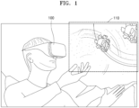
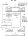
- FIG. 1 is a conceptual diagram for explaining a method for processing a 360-degree image according to an embodiment.
- an apparatus 100 for processing a 360-degree image may project images on both eyes of a user to recognize a portion 110 of a 360-degree image corresponding to a gaze of the user, to allow the user to experience virtual reality through the 360-degree image.
- the image processing apparatus 100 may provide a method for more efficiently processing non-linear properties existing in a 360-degree image in order to increase the speed at which a 360-degree image is processed.
- the image processing apparatus 100 may divide a 360-degree image into a plurality of regions according to a non-linear direction, and may determine a processing order for each of the divided regions.
- the processing order may be determined according to a position of each region in the 360-degree image and parameters of a capturing device such as a camera by which the 360-degree image is captured.
- the image processing apparatus 100 may determine distortion correction information for each pixel to correct geometric aberration and chromatic aberration that occur in projecting at least a partial region of the 360-degree image. For example, the image processing apparatus 100 may preapply a value capable of offsetting a distortion that occurs in the projection, to each pixel included in the image to be projected.
- the image processing apparatus 100 may separately generate images to be projected onto the left eye and the right eye to allow the user to perceive a stereoscopic feeling.
- the image processing apparatus 100 may determine a stereoscopic delta value that is a pixel transformation value required for generating a left-eye image and a right-eye image, in consideration of a vision perception characteristic of the left and right eyes of a human being.
- the image processing apparatus 100 may load segment data or pixel data from a 360-degree image according to the determined processing order, and process the image by applying distortion correction information, the stereoscopic delta value, and so forth to the loaded data, thereby reducing time, memory, and so forth, required for image processing.
- the 360-degree image may include at least one of a fisheye image, a spherical panoramic image, and a cylindrical panoramic image.
- this is merely an example, and the 360-degree image is not limited to the above-described examples.
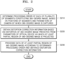
- FIG. 2 is a flowchart for explaining a method for processing a 360-degree image according to an embodiment.
- an image processing apparatus may determine a processing order of each of a plurality of segments constituting a 360-degree image, based on positions of the segments and parameters of a camera by which the 360-degree image is captured.
- An image processing apparatus may perform segmentation that divides a screen into a plurality of segments having a predefined size.
- a segment processing order may be determined based on at least one of a position of a segment and a position of the camera according to the nonlinearity of projection of a 360-degree image.
- the image processing apparatus may determine a bypassing order with respect to a plurality of pixels included in a segment.
- the image processing apparatus may preferentially load a pixel located at a boundary point of a segment in order to minimize latency. Then the image processing apparatus may bypass the pixels from a set top vertex along a predefined direction.
- the image processing apparatus may obtain distortion correction information according to a distortion in the 360-degree image predicted based on parameters of an optical device from which at least a partial region of the 360-degree image is output.
- the image processing apparatus may predict a geometric distortion that occurs when projecting an image, based on parameters of a lens included in an optical system via which at least a partial region of a 360-degree image is projected.
- the image processing apparatus may pre-distort each of pixels included in at least a partial region of the 360-degree image in an opposite direction in order to offset the predicted geometric distortion.
- the image processing apparatus may predict chromatic aberration with respect to RGB components each constituting pixels included in at least a partial region of the 360-degree image.
- the image processing apparatus may offset the predicted chromatic aberration, and may pre-distort components for each color such that an image of the RGB components may be formed on a single focus.
- the image processing apparatus may further determine a coordinate transformation value of a pixel included in at least a partial region of the 360-degree image according to transformation information of left-eye and right-eye images predefined based on a vision perception characteristic. This will be described in more detail with reference to FIGS. 9A and 9B .
- the image processing apparatus may process data of at least a partial region of the 360-degree image according to the determined processing order and the obtained distortion correction information.
- the image processing apparatus may load data of segments included in at least a partial region of the 360-degree image and data of pixels included in each segment, according to the determined processing order.
- the image processing apparatus may transform the loaded data based on the distortion correction information.
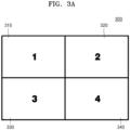
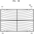
- FIGS. 3A to 3E are diagrams for explaining a method for determining a processing order by dividing, by an image processing apparatus according to an embodiment, a 360-degree image into a plurality of segments.
- the image processing apparatus may divide a 360-degree image 300 into quadrants according to a central axis of a camera that is a device by which the 360-degree image 300 is captured.
- each of the quadrants 310, 320, 330, and 340 divided from the 360-degree image 300 by the image processing apparatus has non-linearity in different directions.
- their shapes and sizes may be distorted.
- segmentation may be performed on each of the quadrants 310, 320, 330, and 340 of the 360-degree image 300.
- the image processing apparatus may perform segmentation that divides each of the four quadrants 310, 320, 330, and 340 of the 360-degree image 300 into a plurality of segments of a 7 ⁇ 7 configuration.
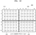
- the image processing apparatus may determine an order in which a plurality of segments are bypassed after performing segmentation. For example, the image processing apparatus may determine an order in which a plurality of segments are bypassed based on a position of a segment and parameters of a camera by which the 360-degree image 300 is captured. This will be described with reference to FIGS. 3C to 3E .
- a bypass order of a plurality of segments determined by the image processing apparatus in the case where a pitch value of a camera is greater than or equal to ⁇ /4 and is within a range of 3 ⁇ /4, is illustrated.
- the image processing apparatus may determine an order in which a plurality of segments included in the first quadrant 310 and the fourth quadrant 340 are bypassed, to be right-to-left.
- the image processing apparatus may determine an order in which a plurality of segments included in the second quadrant 320 and the third quadrant 330 are bypassed, to be left-to-right.
- the image processing apparatus may determine an order in which a plurality of segments included in the first quadrant 310 and the third quadrant 330 are bypassed, to be right-to-left.
- the image processing apparatus may determine an order in which a plurality of segments included in the second quadrant 320 and the fourth quadrant 340 are bypassed, to be left-to-right.
- the image processing apparatus may determine an order in which a plurality of segments included in the first quadrant 310 and the third quadrant 330 are bypassed, to be left-to-right.
- the image processing apparatus may determine an order in which a plurality of segments included in the second quadrant 320 and the fourth quadrant 340 are bypassed, to be right-to-left.
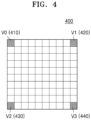
- FIG. 4 is a diagram for explaining a top vertex defined by an image processing apparatus according to an embodiment to determine an order of processing of pixels in a segment.
- an order in which pixels are processed in a segment may be based on the quadrants and the pitch of the camera described with reference to FIG. 3 .
- Pixel processing in each segment may be initiated at a top vertex.
- pixel processing may be initiated at any one of top vertices V0 410, V1 420, V2 430, and V3 440 in a segment 400.
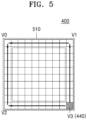
- FIG. 5 is a diagram for explaining a method for processing, by an image processing apparatus according to an embodiment, pixels in a segment.
- the image processing apparatus may preferentially process a boundary region 510 of the segment 400 first in order to reduce latency. For example, in the case where the top vertex V3 440 is determined as a top vertex at which pixel processing is initiated, the image processing apparatus may preferentially process the boundary region 510 of the segment 400 based on the top vertex V3 440 as a starting point. The image processing apparatus may pre-load data required for pixel processing of the segment 400 by preferentially processing the boundary region 510 of the segment 400.
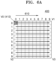
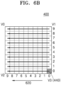
- FIGS. 6A and 6B are diagrams for explaining a method for determining, by an image processing apparatus according to an embodiment, an order of processing of pixels in the segment 400.
- the image processing apparatus may determine the top vertex V0 410 as a top vertex at which pixel processing is initiated in the segment 400.
- the image processing apparatus may determine a top vertex at which pixel processing is initiated based on at least one of the bypass order of the segment and the pitch of the camera, but this is only an example, and the top vertex at the pixel processing is initiated may be arbitrarily determined based other aspects.
- the image processing apparatus may determine a processing order of 10x10 pixels included in the segment 400 to be left-to-right based on the top vertex V0 410 as a starting point.
- the image processing apparatus may determine the top vertex V3 440 as a top vertex at which pixel processing is initiated in the segment 400.
- the image processing apparatus may determine the processing order of the 1 0x10 pixels included in the segment 400 to be right-to-left based on the top vertex V3 440 as a starting point.
- FIG. 7 a diagram for explaining a method for determining, by an image processing apparatus according to an embodiment, an image vector based on parameters of a camera by which a 360-degree image is captured.
- the image processing apparatus may determine an image vector that is a vector from a center 710 of the sphere onto which the 360-degree image is projected, to a center 750 of an image, based on position information of the camera.
- an image vector that is a vector from a center 710 of the sphere onto which the 360-degree image is projected, to a center 750 of an image, based on position information of the camera.
- the image processing apparatus may define a position of a camera as yaw, pitch, and roll values.
- the yaw, pitch, and roll values of the camera are ⁇ , ⁇ , ⁇ , respectively.
- the image processing apparatus may determine (X, Y, Z) coordinates of Cam DIR 720 which is a camera direction vector corresponding to a direction perpendicular to a plane of the image from the center 710 of the sphere based on the position of the camera, according to the following Equation 1.
- the image processing apparatus may determine (X, Y, Z) coordinates of Cam UP 730 which is an upward direction vector of the camera starting from the center 750 of the plane of the image, according to the following Equation 2.
- X cos ⁇ ⁇ cos ⁇ ⁇ cos ⁇ ⁇ sin ⁇ ⁇ sin ⁇ ⁇ ⁇ up
- Y cos ⁇ ⁇ cos ⁇ ⁇ sin ⁇ + sin ⁇ ⁇ cos ⁇ ⁇ ⁇ up
- Z ⁇ cos ⁇ ⁇ sin ⁇ ⁇ ⁇ up
- Equation 2 Y up denotes a vertical coefficient depending on a field of view (FOV) of the camera.
- the image processing apparatus may determine (X, Y, Z) coordinates of Cam RIGH 740 which is a right direction vector of the camera starting from the center 750 of the plane of the image, according to the following Equation 3.
- X ⁇ sin ⁇ ⁇ cos ⁇ ⁇ cos ⁇ ⁇ cos ⁇ ⁇ sin ⁇ ⁇ ⁇ r
- Y ⁇ sin ⁇ ⁇ cos ⁇ ⁇ sin ⁇ + cos ⁇ ⁇ cos ⁇ ⁇ ⁇ r
- Z sin ⁇ ⁇ sin ⁇ ⁇ r
- ⁇ r denotes a horizontal coefficient depending on the field of view (FOV) of the camera.
- the image processing apparatus may determine img ORIG which is an image vector from the center 710 of the sphere toward the center 750 of the image, based on values of Cam DIR 720, Cam UP 730, and Cam RIGH 740, according to the following Equation 4.
- ⁇ img ORIG ⁇ Cam DIR ⁇ ⁇ Cam RIGH ⁇ 0.5 ⁇ ⁇ Cam up ⁇ 0.5
- FIG. 8 is a diagram for explaining a method for correcting, by an image processing apparatus according to an embodiment, geometric aberration for 360-degree image processing.
- an optical system 820 used for projecting at least a partial region 810 of a 360-degree image onto both eyes of a user may include a pair of lenses. Meanwhile, geometric aberration such as a barrel distortion or a pincushion distortion may occur due to the pair of lenses constituting the optical system.
- the image processing apparatus may correct the geometric aberration based on an optical invariant, such as Lagrange invariant or Smith-Helmholtz invariant.
- an optical invariant such as Lagrange invariant or Smith-Helmholtz invariant.
- the image processing apparatus may obtain an image 830 in which geometric aberration occurs as the at least a partial region 810 of the 360-degree image is projected via the optical system 820.
- the image processing apparatus may pre-correct a value of each of a plurality of pixels included in the at least a partial region 810 of the 360-degree image based on an optical backpropagation approach. That is, the image processing apparatus may pre-distort the pixels in the direction opposite to a direction in which a distortion occurs.
- the distortion generated by the optical system 820 may be offset, and thus, a projected image 840 in which geometric aberration is not generated may be obtained.
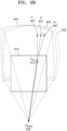
- FIGS. 9A and 9B are diagrams for explaining a method for processing, by an image processing apparatus according to an embodiment, a 360-degree image to obtain a stereoscopic effect.
- the image processing apparatus may allow a user to perceive a stereoscopic feeling by projecting at least a partial region 910 of the 360-degree image onto both eyes of the user.
- images projected onto both eyes of the user may be different from each other such that the user may perceive a stereoscopic feeling.
- a range 935 in which the at least a partial region of the 360-degree image is projected based on a center 930 of the left eye may be different from a range 945 in which the at least a partial region of the 360-degree image is projected based on a center 940 of the right eye.
- the image processing apparatus may obtain a stereoscopic effect by generating the images to be projected onto the left eye and the right eye respectively, to be different from each other.
- the image processing apparatus may determine a point of each of left and right eyes onto which P SCR 912 which is a pixel included in a target image 910 is projected.
- the image processing apparatus may generate a left-eye image and a right-eye image to which binocular disparity is applied, by processing a pixel corresponding to P SCR 912 in the image to be projected to the left eye to be projected onto P L 937, and processing a pixel corresponding to P SCR 912 in the image to be projected to the right eye to be projected onto P R 947.
- the image processing apparatus may more efficiently generate the left-eye image and the right-eye image to which the binocular disparity is applied based on a lookup table pre-generated based on characteristics of the left eye and the right eye.
- FIG. 10 is a diagram for explaining a method for correcting, by an image processing apparatus according to an embodiment, chromatic aberration for 360-degree image processing.
- each of colors constituting a pixel is projected via an optical system 1010, an image is formed at different points since the colors have wavelength values different from each other.
- a pixel is defined by red, green, and blue (RGB) components
- RGB red, green, and blue
- a point 1030 where an image of the blue component is formed may be located in the front
- a point 1040 where an image of the red component is formed may be located in the rear.
- the image processing apparatus may correct the RGB components included in each pixel of the determined left-eye and right-eye images, based on a chromatic aberration value.
- a back-propagation method may be applied based on parameters of the optical system to compensate for an occurrence of color aberration. That is, the image processing apparatus may pre-distort values of the R component and the B component such that the images of the R component and the B component may be formed at the point where the image of the G component is formed.
- the parameters of the optical system may include a refractive index, a focal length, a radius of curvature, and so forth of at least one lens constituting the optical system 1010.
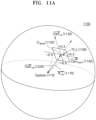
- FIG. 11A is a diagram for explaining a method for determining, by an image processing apparatus according to an embodiment, a pixel vector of an image.
- Cam DIR 1120, Cam up 1130, Cam RIGH 1140, and Img ORIG which is the image vector from a center 1110 of the sphere toward a center 1150 of the image, have been obtained based on the position information of the camera.
- Cam DIR 1120, Cam up 1130, Cam RIGH 1140, and Img ORIG of FIG. 11 may correspond to Cam DIR 720, Cam up 730, Cam RIGH 740, and Img ORIG of FIG. 7 , respectively.
- the image processing apparatus may determine R PIX 1170 which is a pixel vector of a pixel P 1160 located at, for example, coordinates (i, j) in an image, based on the following Equation 5.
- R PIX ⁇ img ORIG + ⁇ Cam up ⁇ k h + ⁇ Cam RIGH ⁇ k w
- Equation 6 w and h denote a width and a height of the image, respectively.
- the pixel P 1160 targets a pixel for a blue color.
- Pixel vectors for a red color and a green color may be determined, in consideration of the chromatic aberration described above with reference to FIG. 10 , based on positions of pixels in which the chromatic aberration has been corrected.
- FIG. 11B is a diagram for explaining a method for determining, by an image processing apparatus according to an embodiment, a projection position in the case of projecting pixels of an image onto a sphere.
- the image processing apparatus may determine P' ( ⁇ , ⁇ ) 1180 which is a projection position on the sphere 1100 based on the following Equation 7.
- ⁇ acos y R ⁇ R PIX ⁇ k ⁇
- ⁇ atan z R x R ⁇ k ⁇
- R PIX 1160 may correspond to the pixel vector described above with reference to FIG. 11A
- x R ,y R ,z R denote cartesian coordinates of R PIX 1160
- k ⁇ , k ⁇ denote scale factors for transformation of an angular unit in radians into a pixel unit.
- FIGS. 12A and 12B are flowcharts for more specifically explaining a method for processing, by an image processing apparatus according to an embodiment, a 360-degree image.
- the image processing apparatus may obtain input data.
- the input data may include a source image 1211, a camera parameter 1212, and an optical system parameter 1213.
- the source image 1211 may be a 360-degree image.
- the camera parameter 1212 may include position information of a camera
- the optical system parameter 1213 may include a refractive index, a focal length, a radius of curvature, and so forth of at least one lens constituting the optical system.
- the image processing apparatus may determine the position of the camera. Accordingly, the image processing apparatus may obtain three-dimensional camera coordinates 1216.
- the image processing apparatus may prepare an image.
- the preparing of the image may include segmentation S1221 and bypassing pixels in a segment S1222.
- the image processing apparatus may perform the segmentation that divides a screen into a plurality of segments having a predefined size.
- a segment processing order may be determined based on at least one of a position of the segment and the position of the camera, according to the nonlinearity of projection of a 360-degree image.
- the image processing apparatus may determine a bypassing order with respect to a plurality of pixels included in a segment.
- the image processing apparatus may preferentially load a pixel located at a boundary point of a segment in order to minimize latency. Then, the image processing apparatus may bypass the pixels from a set top vertex along a predefined direction.
- the image processing apparatus may correct geometric aberration.
- the image processing apparatus may predict geometric aberration that may occur in the image based on the parameters of the optical system.
- the geometric aberration may include, for example, a barrel distortion, a pincushion distortion and so forth.
- the image processing apparatus may pre-distort coordinates of a pixel in a reverse direction of the predicted geometric aberration. Accordingly, the image processing apparatus may obtain pre-distorted pixel coordinates 1226.
- the image processing apparatus may obtain a pixel vector in the image.
- the pixel vector may be a vector from a center of a sphere onto which the image is projected, to the pre-distorted pixel coordinates 1226. Accordingly, the image processing apparatus may obtain three-dimensional coordinates 1231 of the pixel vector.
- the image processing apparatus may project the image onto the sphere.
- the image processing apparatus may obtain spherical coordinates representing a position of a pixel on the sphere. This may correspond to those described with reference to FIG. 11B . Accordingly, the image processing apparatus may obtain spherical coordinates 1236 of a projected pixel.
- the image processing apparatus may determine a delta value for the pixel.
- the delta value may include at least one of a delta value for a stereoscopic effect and a delta value for correction of chromatic aberration.
- the image processing apparatus may determine a stereoscopic delta value.
- the image processing apparatus may generate a left-eye image and a right-eye image to be different from each other such that a user viewing the image may perceive stereoscopic depth.
- the left-eye image and the right-eye image may be generated by moving each of pixels included in the images according to the vision characteristics of a human being.
- the image processing apparatus may determine the stereoscopic delta value for moving pixels to generate a left-eye image and a right-eye image.
- the stereoscopic delta value 1242 for the left-eye image and the right-eye image may be provided in a form of a lookup table.
- the image processing apparatus may determine a color delta value. Different color components constituting each of the pixels included in the image may have focal lengths different from each other due to a difference between refractive indices in each wavelength, when passing through a lens of the optical system.
- the image processing apparatus may determine the color delta value to correct a point where focuses are formed at different positions for each color. In this case, in the case where a pixel is defined by red, green, and blue colors, the image processing apparatus may determine the delta value 1244 with respect to the red component and the blue component based on the green component.
- the image processing apparatus may produce a stereoscopic effect based on the spherical coordinates 1236 of the pixel and the stereoscopic delta value 1242 for the left-eye image and the right-eye image.
- the producing of the stereoscopic effect may include correcting the coordinates of the left-eye image (S1251) and correcting the coordinates of the right-eye image (S1252).
- the image processing apparatus may correct the spherical coordinates 1236 of the pixel based on the stereoscopic delta value for the left-eye image.
- the image processing apparatus may correct the spherical coordinates 1236 of the pixel based on the stereoscopic delta value for the right-eye image.
- the image processing apparatus may obtain spherical coordinates 1253 of pixels of the left-eye image and the right-eye image with respect to the green component, as a result of producing the stereoscopic effect.
- the image processing apparatus may correct chromatic aberration based on the spherical coordinates 1253 of the pixels of the left-eye image and the right-eye image with respect to the green component.
- the correcting of the chromatic aberration may include pre-distorting colors of the left-eye image (S1256) and pre-distorting colors of the right-eye image (S1257).
- the image processing apparatus may correct the spherical coordinates of the pixels of the left-eye image for the green component based on the delta value for the blue component and the red component.
- the back-propagation method described above with reference to FIG. 10 may be used.
- the image processing apparatus may correct the spherical coordinates of the pixels of the right-eye image for the green component based on the delta value for the blue component and the red component.
- the image processing apparatus may analyze a segment boundary based on spherical coordinates 1258 of a segment boundary with respect to RGB colors obtained by performing chromatic aberration correction.
- the image processing apparatus may generate a data request.
- the image processing apparatus may preferentially generate an order of a data request for a pixel located at the segment boundary.
- the image processing apparatus may determine a data request order based on the position of the segment, the position of the camera, and so forth.
- the image processing apparatus may store data obtained from the source image 1211 in response to a data request.
- the image processing apparatus may generate an output image based on a segment 1271 of the source image and spherical coordinates 1259 of the pixels of the left-eye image and the right-eye image with respect to the RGB colors.
- the generating of the output image by the image processing apparatus may include generating the left-eye image (S1276) and generating the right-eye image (S1277).
- the image processing apparatus may output the generated image.
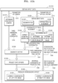
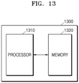
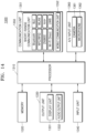
- FIGS. 13 and 14 are block diagrams of an image processing apparatus 1300 according to an embodiment.
- the image processing apparatus 1300 may include a processor 1310 and a memory 1320. However, not all illustrated elements are indispensable elements. The image processing apparatus 1300 may be implemented with more elements than the illustrated elements, or the image processing apparatus 1300 may be implemented with fewer elements than the illustrated elements.
- the image processing apparatus 1300 may further include an output unit 1330, an input unit 1340, a communication unit 1350, and an A/V input unit 1360 in addition to the processor 1310 and the memory 1320.
- the processor 1310 generally controls an overall operation of the image processing apparatus 1300 and a signal flow between internal components of the image processing apparatus 1300, and processes data.
- the processor 1310 may control the output unit 1330, the input unit 1340, the communication unit 1350, and the A/V input unit 1360 overall by executing programs (one or more instructions) stored in the memory 1320.
- the processor 1320 may determine a processing order of each of a plurality of segments constituting a 360-degree image based on a position of each segment and parameters of a camera by which the 360-degree image is captured.
- the processor 1320 may obtain distortion correction information based on a distortion in the 360-degree image predicted from parameters of an optical device via which at least a partial region of the 360-degree image is projected.
- the processor 1320 may process data of the at least a partial region of the 360-degree image according to the determined processing order and the obtained distortion correction information.
- the memory 1320 may store programs (for example, one or more instructions and a learning network model) for processing and controlling the processor 1310, and may store data (for example, additional information) input to the image processing apparatus 1300 or output from the image processing apparatus 1300.
- programs for example, one or more instructions and a learning network model
- data for example, additional information
- the output unit 1330 may output information on the at least a partial region of the image 360 processed by the processor 1310 in a form of an audio signal or a video signal, and the output unit 1330 may include a display unit 1331 and an audio output unit 1332.
- the display unit 1331 may display information processed by the image processing apparatus 1300.
- the display unit 1331 and a touch pad form a layer structure to constitute a touch screen
- the display unit 1331 may be used as an input device as well as an output device.
- the audio output unit 1332 may output audio data received from the communication unit 1350 or stored in the memory 1320.
- the audio output unit 1332 may output sound data corresponding to the at least a partial region of the 360-degree image.
- the input unit 1340 may be a means by which a user inputs data for controlling the image processing apparatus 1300.
- the input unit 1340 may include, but is not limited to, a key pad, a dome switch, a touch pad (a contact capacitive type touch pad, a pressure resistive type touch pad, an infrared sensing type touch pad, a surface acoustic wave type touch pad, an integral strain gauge type touch pad, a piezo effect type touch pad, etc.), a jog wheel, a jog switch, and so forth.
- the communication unit 1350 may receive a 360-degree image captured by a capturing apparatus such as a camera.
- the communication unit 1350 may include one or more elements that enable communications with an external server and other external devices (for example, an object).
- the communication unit 1350 may include a short-range wireless communication unit 1351 and a mobile communication unit 1352.
- the short-range wireless communication unit 1351 may include, but is not limited to, a Bluetooth communication unit, a Bluetooth Low Energy (BLE) communication unit, a near field communication (NFC) / radio-frequency identification (RFID) communication unit, a WLAN (Wi-Fi) communication unit, a Zigbee communication unit, an infrared data association (IrDA) communication unit, a WFD (Wi-Fi Direct) communication unit, an ultra wideband (UWB) communication unit, an Ant+ communication unit, and so forth.
- BLE Bluetooth Low Energy
- NFC near field communication
- RFID radio-frequency identification
- WLAN Wi-Fi
- Zigbee communication unit a Zigbee communication unit
- IrDA infrared data association
- WFD Wi-Fi Direct
- UWB ultra wideband
- the mobile communication unit 1352 may transmit and receive a wireless signal to and from at least one of a base station, an external terminal, and a server over a mobile communication network.
- the A/V (Audio/Video) input unit 1360 is to input an audio signal or a video signal and may include a camera 1361, a microphone 1362, and so forth.
- the camera 1361 may capture a 360-degree image within a camera recognition range. According to an embodiment, a 360-degree image captured by the camera 1361 may be processed by the processor 1310 and displayed via the display unit 1331.
- the microphone 1362 may receive a user's voice input related to processing of a 360-degree image.
- the method according to an embodiment of the present disclosure may be implemented in the form of a program instruction that may be executed by various computer means and may be recorded in a computer-readable medium.
- the computer-readable medium may include a program instruction, a data file, a data structure or the like, alone or in combination.
- the program instruction to be recorded in the medium may be specially designed and configured for the present disclosure or may be known to those of ordinary skill in computer software.
- Examples of the computer-readable medium include magnetic media such as a hard disk, a floppy disk, and a magnetic tape, optical media such as a CD-ROM and a DVD, magneto-optical media such as a floptical disk, and hardware devices specially configured to store and perform program instructions such as a ROM, a RAM, a flash memory, and so forth.
- Examples of the program instruction include machine code, such as that produced by a compiler, and high-level language code that may be executed by a computer using an interpreter.
- the apparatus may include a processor, a memory for storing and executing program data, a permanent storage such as a disk drive, a communication port for communications with external devices, and user interface devices such as a touch panel, keys, buttons, and so forth.
- Methods implemented with software modules or algorithms may be stored on a computer-readable recording medium, as computer-readable code or program instructions executable on the processor.
- Examples of the computer-readable recording medium include magnetic storage media (for example, read-only memory (ROM), random-access memory (RAM), floppy disks, hard disks, and so forth), optical recording media (for example, CD-ROMs, digital versatile disks (DVDs)), and so forth.
- the computer-readable recording medium may be distributed over network-coupled computer systems such that computer-readable code may be stored and executed in a distributed fashion. The medium may be read by a computer, stored in a memory, and executed by a processor.
- the embodiments may be described in terms of functional block components and various processing operations. Such functional blocks may be implemented with a variety of hardware and/or software configurations for executing specific functions. For example, the embodiments may employ various integrated circuit components, such as memory, processing, logics, look-up tables, and so forth, which may carry out a variety of functions under the control of one or more microprocessors or by other control devices. In addition, the embodiments may employ the same kind or different kinds of cores or different kinds of CPUs.
- the embodiments may be implemented with a programming or scripting language such as C, C++, Java, assembler, or the like, with various algorithms implemented with any combination of data structures, processes, routines or other programming elements.
- Functional aspects may be implemented with algorithms executable in one or more processors.
- the embodiments may employ conventional technologies for electronic environment setting, signal processing, and/or data processing.
- the terms "mechanism”, “element”, “means”, and “configuration” may be widely used and are not limited to mechanical and physical configurations. The terms may include the meaning of a series of routines of software in conjunction with a processor or the like.
- connections or connection members of the lines between the elements illustrated in the drawings are exemplarily illustrative of functional connections and/or physical or circuit connections, and may be alternatively or additionally represented as various functional connections, physical connections, or circuit connections in actual devices.
Landscapes
- Engineering & Computer Science (AREA)
- Multimedia (AREA)
- Signal Processing (AREA)
- Physics & Mathematics (AREA)
- General Physics & Mathematics (AREA)
- Optics & Photonics (AREA)
- Theoretical Computer Science (AREA)
- Image Processing (AREA)
- Studio Devices (AREA)
Claims (7)
- Verfahren zur Verarbeitung eines 360-Grad-Bildes, wobei das Verfahren Folgendes umfasst:Aufteilen des 360-Grad-Bildes in eine Vielzahl von einander überlappenden Segmenten, wobei das 360-Grad-Bild ein Fischaugenbild umfasst;Bestimmen (S210) einer Verarbeitungsreihenfolge der Vielzahl von zu verarbeitenden Segmenten unter Verwendung einer Position der Vielzahl von Segmenten in einem Quadranten und von Parametern einer Kamera, mit der das 360-Grad-Bild aufgenommen wird, wobei innerhalb eines Segments die Pixel des Randbereichs des Segments als vor anderen Pixeln zu verarbeitend bestimmt werden;Erhalten (S220) von Verzerrungskorrekturinformationen gemäß einer Verzerrung, die auf der Grundlage von Parametern eines optischen Geräts vorhergesagt wird, das zumindest einen Teilbereich des 360-Grad-Bildes auf die Augen eines Benutzers projiziert; undVerarbeiten (S230) von Segmenten, die in zumindest einem Teilbereich der Vielzahl von Segmenten enthalten sind, gemäß der Verarbeitungsreihenfolge und den erhaltenen Verzerrungskorrekturinformationen.
- Verfahren nach Anspruch 1, wobei das Erhalten (S220) der Verzerrungskorrekturinformationen das Vorhersagen von mindestens einer der folgenden Verzerrungen umfasst tonnenförmige Verzerrung und kissenförmige Verzerrung basierend auf den Parametern des optischen Geräts, und die Verzerrungskorrekturinformationen Pixelkorrekturinformationen umfassen, mit denen zumindest eine der tonnenförmigen Verzerrungen und/oder die kissenförmige Verzerrung ausgeglichen werden kann.
- Verfahren nach Anspruch 1, wobei das Erhalten (S220) der Verzerrungskorrekturinformationen
das Vorhersagen der chromatischen Aberration eines Pixels umfasst, das in dem 360-Grad-Bild enthalten ist, basierend auf den Parametern des optischen Geräts, und die Verzerrungskorrekturinformationen Pixelkorrekturinformationen für jede Farbe umfassen, mit denen die vorhergesagte chromatische Aberration ausgeglichen werden kann. - Vorrichtung (1300) zum Verarbeiten eines 360-Grad-Bildes, wobei die Vorrichtung Folgendes umfasst:einen Speicher (1320), der eine oder mehrere Anweisungen speichert; undeinen Prozessor (1310), der so konfiguriert ist, dass er die eine oder mehrere Anweisungen ausführt, die im Speicher (1320) gespeichert sind, wobeider Prozessor (1310) dazu konfiguriert ist, durch Ausführen der einen oder mehreren Anweisungen,das 360-Grad-Bild in eine Vielzahl von einander überlappenden Segmenten aufzuteilen, wobei das 360-Grad-Bild ein Fischaugenbild umfasst,eine Verarbeitungsreihenfolge der Vielzahl von zu verarbeitenden Segmenten unter Verwendung einer Position der Vielzahl von Segmenten in einem Quadranten und von Parametern einer Kamera zu bestimmen, mit der das 360-Grad-Bild aufgenommen wird, wobei innerhalb eines Segments die Pixel des Randbereichs des Segments als vor anderen Pixeln zu verarbeitende Pixel bestimmt werden,Verzerrungskorrekturinformationen basierend auf einer Verzerrung zu erhalten, die aus Parametern eines optischen Geräts vorhergesagt wird, das zumindest einen Teilbereich des 360-Grad-Bildes auf die Augen eines Benutzers projiziert, undSegmente, die in dem zumindest einen Teilbereich unter der Vielzahl von Segmenten enthalten sind, gemäß der Verarbeitungsreihenfolge und den erhaltenen Verzerrungskorrekturinformationen zu verarbeiten.
- Vorrichtung (1300) nach Anspruch 4, wobei der Prozessor (1310) dazu konfiguriert ist, durch Ausführen der einen oder mehreren Anweisungen, mindestens eine der folgenden Verzerrungen vorherzusagen tonnenförmige und kissenförmige Verzerrung basierend auf den Parametern des optischen Geräts, und
die Verzerrungskorrekturinformationen Pixelkorrekturinformationen umfassen, die in der Lage sind, mindestens eine der tonnenförmigen und kissenförmigen Verzerrungen auszugleichen. - Vorrichtung (1300) nach Anspruch 4, wobei der Prozessor (1310) dazu konfiguriert ist, durch Ausführen der einen oder mehreren Anweisungen, die chromatische Aberration eines im 360-Grad-Bild enthaltenen Pixels anhand der Parameter des optischen Geräts vorherzusagen, und
die Verzerrungskorrekturinformationen Pixelkorrekturinformationen für jede Farbe umfassen, mit denen die vorhergesagte chromatische Aberration ausgeglichen werden kann. - Computerprogrammprodukt, das ein computerlesbares Aufzeichnungsmedium umfasst, auf dem ein Programm für Folgendes gespeichert ist:Aufteilen des 360-Grad-Bildes in eine Vielzahl von einander überlappenden Segmenten, wobei das 360-Grad-Bild ein Fischaugenbild umfasst;Bestimmen (S210) einer Verarbeitungsreihenfolge der Vielzahl von zu verarbeitenden Segmenten unter Verwendung einer Position der Vielzahl von Segmenten in einem Quadranten und von Parametern einer Kamera, mit der das 360-Grad-Bild aufgenommen wird, wobei innerhalb eines Segments die Pixel des Randbereichs des Segments als vor anderen Pixeln zu verarbeitend bestimmt werden;Erhalten (S220) von Verzerrungskorrekturinformationen gemäß einer Verzerrung, die auf der Grundlage von Parametern eines optischen Geräts vorhergesagt wird, das zumindest einen Teilbereich des 360-Grad-Bildes auf die Augen eines Benutzers projiziert; undVerarbeiten (S230) von Segmenten, die in mindestens einem Teilbereich der Vielzahl von Segmenten enthalten sind, gemäß der Verarbeitungsreihenfolge und den erhaltenen Verzerrungskorrekturinformationen.
Applications Claiming Priority (2)
| Application Number | Priority Date | Filing Date | Title |
|---|---|---|---|
| KR1020180070821A KR102435519B1 (ko) | 2018-06-20 | 2018-06-20 | 360도 영상을 처리하는 방법 및 장치 |
| PCT/KR2019/007444 WO2019245299A1 (ko) | 2018-06-20 | 2019-06-20 | 360도 영상을 처리하는 방법 및 장치 |
Publications (3)
| Publication Number | Publication Date |
|---|---|
| EP3764641A1 EP3764641A1 (de) | 2021-01-13 |
| EP3764641A4 EP3764641A4 (de) | 2021-04-14 |
| EP3764641B1 true EP3764641B1 (de) | 2024-07-31 |
Family
ID=68983308
Family Applications (1)
| Application Number | Title | Priority Date | Filing Date |
|---|---|---|---|
| EP19823527.7A Active EP3764641B1 (de) | 2018-06-20 | 2019-06-20 | Verfahren und vorrichtung zur verarbeitung eines 360-grad-bildes |
Country Status (5)
| Country | Link |
|---|---|
| US (1) | US11989849B2 (de) |
| EP (1) | EP3764641B1 (de) |
| KR (1) | KR102435519B1 (de) |
| CN (1) | CN112313947B (de) |
| WO (1) | WO2019245299A1 (de) |
Families Citing this family (4)
| Publication number | Priority date | Publication date | Assignee | Title |
|---|---|---|---|---|
| WO2020229995A1 (en) * | 2019-05-10 | 2020-11-19 | Roderick Victor Kennedy | Reduction of the effects of latency for extended reality experiences |
| KR102522892B1 (ko) * | 2020-03-12 | 2023-04-18 | 한국전자통신연구원 | 가상 시점 영상을 합성하기 위한 입력 영상을 제공하는 카메라 선별 방법 및 장치 |
| KR20250101480A (ko) * | 2023-12-27 | 2025-07-04 | 삼성전자주식회사 | 프로젝션 장치 및 그 동작 방법 |
| KR20250109001A (ko) * | 2024-01-09 | 2025-07-16 | 삼성전자주식회사 | 이미지의 왜곡을 보정하는 방법 및 전자 장치 |
Family Cites Families (34)
| Publication number | Priority date | Publication date | Assignee | Title |
|---|---|---|---|---|
| AU3930793A (en) | 1992-05-08 | 1993-12-13 | Apple Computer, Inc. | Textured sphere and spherical environment map rendering using texture map double indirection |
| JP3711707B2 (ja) | 1997-08-07 | 2005-11-02 | ブラザー工業株式会社 | 画像2値化方法、画像2値化装置および記録媒体 |
| US6486908B1 (en) | 1998-05-27 | 2002-11-26 | Industrial Technology Research Institute | Image-based method and system for building spherical panoramas |
| JP4004346B2 (ja) * | 2002-07-31 | 2007-11-07 | 富士フイルム株式会社 | 撮像装置及びディストーション補正方法 |
| JP4324435B2 (ja) | 2003-04-18 | 2009-09-02 | 三洋電機株式会社 | 立体視用映像提供方法及び立体映像表示装置 |
| KR101390810B1 (ko) | 2007-10-04 | 2014-05-26 | 삼성전자주식회사 | 로컬 3차원 영상을 재생하기 위한 파라미터를 포함하는영상 데이터스트림을 수신하는 방법 및 장치, 그리고 로컬3차원 영상을 재생하기 위한 파라미터를 포함하는 영상데이터스트림을 생성하는 방법 및 장치 |
| US8538134B2 (en) | 2007-10-04 | 2013-09-17 | Samsung Electronics Co., Ltd. | Method and apparatus for receiving and generating image data stream including parameters for displaying local three dimensional image |
| US8217956B1 (en) | 2008-02-29 | 2012-07-10 | Adobe Systems Incorporated | Method and apparatus for rendering spherical panoramas |
| JP4857297B2 (ja) | 2008-03-11 | 2012-01-18 | 株式会社日立製作所 | 映像処理装置 |
| JP5790345B2 (ja) | 2011-09-07 | 2015-10-07 | 株式会社リコー | 画像処理装置、画像処理方法、プログラムおよび画像処理システム |
| CN111031302A (zh) | 2012-04-25 | 2020-04-17 | 浙江大学 | 三维视频序列辅助信息的解码方法、编码方法及装置 |
| KR101698657B1 (ko) | 2012-07-04 | 2017-01-20 | 인텔 코포레이션 | 파노라마 기반 3d 비디오 코딩 |
| WO2014043814A1 (en) | 2012-09-21 | 2014-03-27 | Tamaggo Inc. | Methods and apparatus for displaying and manipulating a panoramic image by tiles |
| JP2014123908A (ja) | 2012-12-21 | 2014-07-03 | Jvc Kenwood Corp | 画像処理装置、画像切り出し方法、及びプログラム |
| US9451162B2 (en) * | 2013-08-21 | 2016-09-20 | Jaunt Inc. | Camera array including camera modules |
| JP2017527230A (ja) * | 2014-05-29 | 2017-09-14 | ネクストブイアール・インコーポレイテッド | コンテンツを配信および/または再生するための方法及び装置 |
| US9918136B2 (en) | 2014-05-29 | 2018-03-13 | Nextvr Inc. | Methods and apparatus for delivering content and/or playing back content |
| US10204658B2 (en) | 2014-07-14 | 2019-02-12 | Sony Interactive Entertainment Inc. | System and method for use in playing back panorama video content |
| US10368011B2 (en) * | 2014-07-25 | 2019-07-30 | Jaunt Inc. | Camera array removing lens distortion |
| US9363569B1 (en) * | 2014-07-28 | 2016-06-07 | Jaunt Inc. | Virtual reality system including social graph |
| US20160077315A1 (en) | 2014-09-15 | 2016-03-17 | Remotereality Corporation | Compact panoramic camera: optical system, apparatus, image forming method |
| US9600929B1 (en) | 2014-12-01 | 2017-03-21 | Ngrain (Canada) Corporation | System, computer-readable medium and method for 3D-differencing of 3D voxel models |
| EP3286599A4 (de) | 2015-04-22 | 2018-12-19 | eSIGHT CORP. | Verfahren und vorrichtungen zur korrektur von optischer aberration |
| US10038887B2 (en) | 2015-05-27 | 2018-07-31 | Google Llc | Capture and render of panoramic virtual reality content |
| US10217189B2 (en) | 2015-09-16 | 2019-02-26 | Google Llc | General spherical capture methods |
| US10062151B2 (en) | 2016-01-21 | 2018-08-28 | Samsung Electronics Co., Ltd. | Image deblurring method and apparatus |
| CN106991650B (zh) | 2016-01-21 | 2020-09-15 | 北京三星通信技术研究有限公司 | 一种图像去模糊的方法和装置 |
| KR102523997B1 (ko) | 2016-02-12 | 2023-04-21 | 삼성전자주식회사 | 360도 영상 처리 방법 및 장치 |
| US10433025B2 (en) * | 2016-05-10 | 2019-10-01 | Jaunt Inc. | Virtual reality resource scheduling of process in a cloud-based virtual reality processing system |
| US10650526B2 (en) * | 2016-06-28 | 2020-05-12 | Canon Kabushiki Kaisha | Image processing apparatus, image capturing apparatus, image processing method, and storage medium |
| KR20190035678A (ko) * | 2016-07-08 | 2019-04-03 | 브이아이디 스케일, 인크. | 지오메트리 투영을 이용한 360도 비디오 코딩 |
| US10437545B2 (en) * | 2016-12-28 | 2019-10-08 | Ricoh Company, Ltd. | Apparatus, system, and method for controlling display, and recording medium |
| US10789671B2 (en) * | 2016-12-28 | 2020-09-29 | Ricoh Company, Ltd. | Apparatus, system, and method of controlling display, and recording medium |
| US20190289206A1 (en) * | 2018-03-15 | 2019-09-19 | Keiichi Kawaguchi | Image processing apparatus, image capturing system, image processing method, and recording medium |
-
2018
- 2018-06-20 KR KR1020180070821A patent/KR102435519B1/ko active Active
-
2019
- 2019-06-20 US US17/052,057 patent/US11989849B2/en active Active
- 2019-06-20 EP EP19823527.7A patent/EP3764641B1/de active Active
- 2019-06-20 CN CN201980041461.4A patent/CN112313947B/zh active Active
- 2019-06-20 WO PCT/KR2019/007444 patent/WO2019245299A1/ko not_active Ceased
Also Published As
| Publication number | Publication date |
|---|---|
| US11989849B2 (en) | 2024-05-21 |
| EP3764641A1 (de) | 2021-01-13 |
| EP3764641A4 (de) | 2021-04-14 |
| US20210142442A1 (en) | 2021-05-13 |
| WO2019245299A1 (ko) | 2019-12-26 |
| KR20190143186A (ko) | 2019-12-30 |
| CN112313947B (zh) | 2023-07-18 |
| KR102435519B1 (ko) | 2022-08-24 |
| CN112313947A (zh) | 2021-02-02 |
Similar Documents
| Publication | Publication Date | Title |
|---|---|---|
| EP3764641B1 (de) | Verfahren und vorrichtung zur verarbeitung eines 360-grad-bildes | |
| US11989350B2 (en) | Hand key point recognition model training method, hand key point recognition method and device | |
| JP7441917B2 (ja) | 顔に対する射影歪み補正 | |
| EP3137972B1 (de) | Stabilisierungsebenenbestimmung auf grundlage der blickposition | |
| CN104322060B (zh) | 用于深度图的低等待时间变形的系统、方法和装置 | |
| CN110874135B (zh) | 光学畸变的校正方法、装置、终端设备及存储介质 | |
| WO2020048461A1 (zh) | 三维立体显示方法、终端设备及存储介质 | |
| CN103136744A (zh) | 用于计算特征点的三维位置的装置和方法 | |
| US10948730B2 (en) | Dynamic panel masking | |
| JP7064257B2 (ja) | 画像深度確定方法及び生き物認識方法、回路、装置、記憶媒体 | |
| JP6151930B2 (ja) | 撮像装置およびその制御方法 | |
| WO2018069570A1 (en) | Display of visual data with a virtual reality headset | |
| CN110874867A (zh) | 显示方法、装置、终端设备及存储介质 | |
| US10915736B2 (en) | Image processing method and apparatus | |
| US12519919B2 (en) | Method and system for converting single-view image to 2.5D view for extended reality (XR) applications | |
| US20230052104A1 (en) | Virtual content experience system and control method for same | |
| JP6591667B2 (ja) | 画像処理システム、画像処理装置、及びプログラム | |
| CN111896015A (zh) | 导航方法、装置、存储介质及电子设备 | |
| JP7214926B1 (ja) | 画像処理方法、装置、電子機器及びコンピュータ読み取り可能な記憶媒体 | |
| EP4206977A1 (de) | Elektronische vorrichtung und steuerungsverfahren für elektronische vorrichtung | |
| JP6371547B2 (ja) | 画像処理装置、方法、および、プログラム | |
| KR102913090B1 (ko) | 딥러닝 모델 기반의 사용자 시선에 따른 빔-프로젝터 왜곡 보정하는 전자 장치 및 그 구동방법 | |
| CN115205131B (zh) | 畸变图像校正方法及装置、计算机可读介质和电子设备 | |
| KR20250154834A (ko) | 딥러닝 모델 기반의 사용자 시선에 따른 빔-프로젝터 왜곡 보정하는 전자 장치 및 그 구동방법 | |
| KR20220061812A (ko) | 전자 장치 및 전자 장치의 제어 방법 |
Legal Events
| Date | Code | Title | Description |
|---|---|---|---|
| STAA | Information on the status of an ep patent application or granted ep patent |
Free format text: STATUS: THE INTERNATIONAL PUBLICATION HAS BEEN MADE |
|
| PUAI | Public reference made under article 153(3) epc to a published international application that has entered the european phase |
Free format text: ORIGINAL CODE: 0009012 |
|
| STAA | Information on the status of an ep patent application or granted ep patent |
Free format text: STATUS: REQUEST FOR EXAMINATION WAS MADE |
|
| 17P | Request for examination filed |
Effective date: 20201007 |
|
| AK | Designated contracting states |
Kind code of ref document: A1 Designated state(s): AL AT BE BG CH CY CZ DE DK EE ES FI FR GB GR HR HU IE IS IT LI LT LU LV MC MK MT NL NO PL PT RO RS SE SI SK SM TR |
|
| AX | Request for extension of the european patent |
Extension state: BA ME |
|
| A4 | Supplementary search report drawn up and despatched |
Effective date: 20210312 |
|
| RIC1 | Information provided on ipc code assigned before grant |
Ipc: H04N 13/117 20180101AFI20210308BHEP Ipc: H04N 13/122 20180101ALI20210308BHEP Ipc: H04N 13/344 20180101ALI20210308BHEP Ipc: G02B 27/01 20060101ALI20210308BHEP Ipc: G06T 3/00 20060101ALI20210308BHEP Ipc: G06T 5/00 20060101ALI20210308BHEP |
|
| DAV | Request for validation of the european patent (deleted) | ||
| DAX | Request for extension of the european patent (deleted) | ||
| STAA | Information on the status of an ep patent application or granted ep patent |
Free format text: STATUS: EXAMINATION IS IN PROGRESS |
|
| 17Q | First examination report despatched |
Effective date: 20220817 |
|
| GRAP | Despatch of communication of intention to grant a patent |
Free format text: ORIGINAL CODE: EPIDOSNIGR1 |
|
| STAA | Information on the status of an ep patent application or granted ep patent |
Free format text: STATUS: GRANT OF PATENT IS INTENDED |
|
| RIC1 | Information provided on ipc code assigned before grant |
Ipc: G06T 5/80 20240101ALI20240312BHEP Ipc: G02B 27/01 20060101ALI20240312BHEP Ipc: H04N 13/344 20180101ALI20240312BHEP Ipc: H04N 13/122 20180101ALI20240312BHEP Ipc: H04N 13/117 20180101AFI20240312BHEP |
|
| INTG | Intention to grant announced |
Effective date: 20240405 |
|
| GRAS | Grant fee paid |
Free format text: ORIGINAL CODE: EPIDOSNIGR3 |
|
| GRAA | (expected) grant |
Free format text: ORIGINAL CODE: 0009210 |
|
| STAA | Information on the status of an ep patent application or granted ep patent |
Free format text: STATUS: THE PATENT HAS BEEN GRANTED |
|
| AK | Designated contracting states |
Kind code of ref document: B1 Designated state(s): AL AT BE BG CH CY CZ DE DK EE ES FI FR GB GR HR HU IE IS IT LI LT LU LV MC MK MT NL NO PL PT RO RS SE SI SK SM TR |
|
| REG | Reference to a national code |
Ref country code: CH Ref legal event code: EP Ref country code: GB Ref legal event code: FG4D |
|
| REG | Reference to a national code |
Ref country code: DE Ref legal event code: R096 Ref document number: 602019056234 Country of ref document: DE |
|
| REG | Reference to a national code |
Ref country code: IE Ref legal event code: FG4D |
|
| REG | Reference to a national code |
Ref country code: LT Ref legal event code: MG9D |
|
| REG | Reference to a national code |
Ref country code: NL Ref legal event code: MP Effective date: 20240731 |
|
| PG25 | Lapsed in a contracting state [announced via postgrant information from national office to epo] |
Ref country code: PT Free format text: LAPSE BECAUSE OF FAILURE TO SUBMIT A TRANSLATION OF THE DESCRIPTION OR TO PAY THE FEE WITHIN THE PRESCRIBED TIME-LIMIT Effective date: 20241202 |
|
| REG | Reference to a national code |
Ref country code: AT Ref legal event code: MK05 Ref document number: 1709646 Country of ref document: AT Kind code of ref document: T Effective date: 20240731 |
|
| PG25 | Lapsed in a contracting state [announced via postgrant information from national office to epo] |
Ref country code: PT Free format text: LAPSE BECAUSE OF FAILURE TO SUBMIT A TRANSLATION OF THE DESCRIPTION OR TO PAY THE FEE WITHIN THE PRESCRIBED TIME-LIMIT Effective date: 20241202 |
|
| PG25 | Lapsed in a contracting state [announced via postgrant information from national office to epo] |
Ref country code: NO Free format text: LAPSE BECAUSE OF FAILURE TO SUBMIT A TRANSLATION OF THE DESCRIPTION OR TO PAY THE FEE WITHIN THE PRESCRIBED TIME-LIMIT Effective date: 20241031 |
|
| PG25 | Lapsed in a contracting state [announced via postgrant information from national office to epo] |
Ref country code: NL Free format text: LAPSE BECAUSE OF FAILURE TO SUBMIT A TRANSLATION OF THE DESCRIPTION OR TO PAY THE FEE WITHIN THE PRESCRIBED TIME-LIMIT Effective date: 20240731 Ref country code: FI Free format text: LAPSE BECAUSE OF FAILURE TO SUBMIT A TRANSLATION OF THE DESCRIPTION OR TO PAY THE FEE WITHIN THE PRESCRIBED TIME-LIMIT Effective date: 20240731 Ref country code: PL Free format text: LAPSE BECAUSE OF FAILURE TO SUBMIT A TRANSLATION OF THE DESCRIPTION OR TO PAY THE FEE WITHIN THE PRESCRIBED TIME-LIMIT Effective date: 20240731 Ref country code: GR Free format text: LAPSE BECAUSE OF FAILURE TO SUBMIT A TRANSLATION OF THE DESCRIPTION OR TO PAY THE FEE WITHIN THE PRESCRIBED TIME-LIMIT Effective date: 20241101 |
|
| PG25 | Lapsed in a contracting state [announced via postgrant information from national office to epo] |
Ref country code: BG Free format text: LAPSE BECAUSE OF FAILURE TO SUBMIT A TRANSLATION OF THE DESCRIPTION OR TO PAY THE FEE WITHIN THE PRESCRIBED TIME-LIMIT Effective date: 20240731 |
|
| PG25 | Lapsed in a contracting state [announced via postgrant information from national office to epo] |
Ref country code: LV Free format text: LAPSE BECAUSE OF FAILURE TO SUBMIT A TRANSLATION OF THE DESCRIPTION OR TO PAY THE FEE WITHIN THE PRESCRIBED TIME-LIMIT Effective date: 20240731 |
|
| PG25 | Lapsed in a contracting state [announced via postgrant information from national office to epo] |
Ref country code: IS Free format text: LAPSE BECAUSE OF FAILURE TO SUBMIT A TRANSLATION OF THE DESCRIPTION OR TO PAY THE FEE WITHIN THE PRESCRIBED TIME-LIMIT Effective date: 20241130 Ref country code: AT Free format text: LAPSE BECAUSE OF FAILURE TO SUBMIT A TRANSLATION OF THE DESCRIPTION OR TO PAY THE FEE WITHIN THE PRESCRIBED TIME-LIMIT Effective date: 20240731 |
|
| PG25 | Lapsed in a contracting state [announced via postgrant information from national office to epo] |
Ref country code: HR Free format text: LAPSE BECAUSE OF FAILURE TO SUBMIT A TRANSLATION OF THE DESCRIPTION OR TO PAY THE FEE WITHIN THE PRESCRIBED TIME-LIMIT Effective date: 20240731 |
|
| PG25 | Lapsed in a contracting state [announced via postgrant information from national office to epo] |
Ref country code: RS Free format text: LAPSE BECAUSE OF FAILURE TO SUBMIT A TRANSLATION OF THE DESCRIPTION OR TO PAY THE FEE WITHIN THE PRESCRIBED TIME-LIMIT Effective date: 20241031 Ref country code: ES Free format text: LAPSE BECAUSE OF FAILURE TO SUBMIT A TRANSLATION OF THE DESCRIPTION OR TO PAY THE FEE WITHIN THE PRESCRIBED TIME-LIMIT Effective date: 20240731 |
|
| PG25 | Lapsed in a contracting state [announced via postgrant information from national office to epo] |
Ref country code: RS Free format text: LAPSE BECAUSE OF FAILURE TO SUBMIT A TRANSLATION OF THE DESCRIPTION OR TO PAY THE FEE WITHIN THE PRESCRIBED TIME-LIMIT Effective date: 20241031 Ref country code: PL Free format text: LAPSE BECAUSE OF FAILURE TO SUBMIT A TRANSLATION OF THE DESCRIPTION OR TO PAY THE FEE WITHIN THE PRESCRIBED TIME-LIMIT Effective date: 20240731 Ref country code: NO Free format text: LAPSE BECAUSE OF FAILURE TO SUBMIT A TRANSLATION OF THE DESCRIPTION OR TO PAY THE FEE WITHIN THE PRESCRIBED TIME-LIMIT Effective date: 20241031 Ref country code: NL Free format text: LAPSE BECAUSE OF FAILURE TO SUBMIT A TRANSLATION OF THE DESCRIPTION OR TO PAY THE FEE WITHIN THE PRESCRIBED TIME-LIMIT Effective date: 20240731 Ref country code: LV Free format text: LAPSE BECAUSE OF FAILURE TO SUBMIT A TRANSLATION OF THE DESCRIPTION OR TO PAY THE FEE WITHIN THE PRESCRIBED TIME-LIMIT Effective date: 20240731 Ref country code: IS Free format text: LAPSE BECAUSE OF FAILURE TO SUBMIT A TRANSLATION OF THE DESCRIPTION OR TO PAY THE FEE WITHIN THE PRESCRIBED TIME-LIMIT Effective date: 20241130 Ref country code: HR Free format text: LAPSE BECAUSE OF FAILURE TO SUBMIT A TRANSLATION OF THE DESCRIPTION OR TO PAY THE FEE WITHIN THE PRESCRIBED TIME-LIMIT Effective date: 20240731 Ref country code: GR Free format text: LAPSE BECAUSE OF FAILURE TO SUBMIT A TRANSLATION OF THE DESCRIPTION OR TO PAY THE FEE WITHIN THE PRESCRIBED TIME-LIMIT Effective date: 20241101 Ref country code: FI Free format text: LAPSE BECAUSE OF FAILURE TO SUBMIT A TRANSLATION OF THE DESCRIPTION OR TO PAY THE FEE WITHIN THE PRESCRIBED TIME-LIMIT Effective date: 20240731 Ref country code: ES Free format text: LAPSE BECAUSE OF FAILURE TO SUBMIT A TRANSLATION OF THE DESCRIPTION OR TO PAY THE FEE WITHIN THE PRESCRIBED TIME-LIMIT Effective date: 20240731 Ref country code: BG Free format text: LAPSE BECAUSE OF FAILURE TO SUBMIT A TRANSLATION OF THE DESCRIPTION OR TO PAY THE FEE WITHIN THE PRESCRIBED TIME-LIMIT Effective date: 20240731 Ref country code: AT Free format text: LAPSE BECAUSE OF FAILURE TO SUBMIT A TRANSLATION OF THE DESCRIPTION OR TO PAY THE FEE WITHIN THE PRESCRIBED TIME-LIMIT Effective date: 20240731 |
|
| PG25 | Lapsed in a contracting state [announced via postgrant information from national office to epo] |
Ref country code: DK Free format text: LAPSE BECAUSE OF FAILURE TO SUBMIT A TRANSLATION OF THE DESCRIPTION OR TO PAY THE FEE WITHIN THE PRESCRIBED TIME-LIMIT Effective date: 20240731 Ref country code: SM Free format text: LAPSE BECAUSE OF FAILURE TO SUBMIT A TRANSLATION OF THE DESCRIPTION OR TO PAY THE FEE WITHIN THE PRESCRIBED TIME-LIMIT Effective date: 20240731 Ref country code: RO Free format text: LAPSE BECAUSE OF FAILURE TO SUBMIT A TRANSLATION OF THE DESCRIPTION OR TO PAY THE FEE WITHIN THE PRESCRIBED TIME-LIMIT Effective date: 20240731 |
|
| PG25 | Lapsed in a contracting state [announced via postgrant information from national office to epo] |
Ref country code: EE Free format text: LAPSE BECAUSE OF FAILURE TO SUBMIT A TRANSLATION OF THE DESCRIPTION OR TO PAY THE FEE WITHIN THE PRESCRIBED TIME-LIMIT Effective date: 20240731 |
|
| PG25 | Lapsed in a contracting state [announced via postgrant information from national office to epo] |
Ref country code: CZ Free format text: LAPSE BECAUSE OF FAILURE TO SUBMIT A TRANSLATION OF THE DESCRIPTION OR TO PAY THE FEE WITHIN THE PRESCRIBED TIME-LIMIT Effective date: 20240731 |
|
| PG25 | Lapsed in a contracting state [announced via postgrant information from national office to epo] |
Ref country code: IT Free format text: LAPSE BECAUSE OF FAILURE TO SUBMIT A TRANSLATION OF THE DESCRIPTION OR TO PAY THE FEE WITHIN THE PRESCRIBED TIME-LIMIT Effective date: 20240731 Ref country code: SK Free format text: LAPSE BECAUSE OF FAILURE TO SUBMIT A TRANSLATION OF THE DESCRIPTION OR TO PAY THE FEE WITHIN THE PRESCRIBED TIME-LIMIT Effective date: 20240731 |
|
| REG | Reference to a national code |
Ref country code: DE Ref legal event code: R097 Ref document number: 602019056234 Country of ref document: DE |
|
| PLBE | No opposition filed within time limit |
Free format text: ORIGINAL CODE: 0009261 |
|
| STAA | Information on the status of an ep patent application or granted ep patent |
Free format text: STATUS: NO OPPOSITION FILED WITHIN TIME LIMIT |
|
| 26N | No opposition filed |
Effective date: 20250501 |
|
| PG25 | Lapsed in a contracting state [announced via postgrant information from national office to epo] |
Ref country code: SE Free format text: LAPSE BECAUSE OF FAILURE TO SUBMIT A TRANSLATION OF THE DESCRIPTION OR TO PAY THE FEE WITHIN THE PRESCRIBED TIME-LIMIT Effective date: 20240731 |