EP3764345B1 - Verfahren umgebungslicht zu detektieren, endgerät und speichermedium - Google Patents
Verfahren umgebungslicht zu detektieren, endgerät und speichermedium Download PDFInfo
- Publication number
- EP3764345B1 EP3764345B1 EP20156548.8A EP20156548A EP3764345B1 EP 3764345 B1 EP3764345 B1 EP 3764345B1 EP 20156548 A EP20156548 A EP 20156548A EP 3764345 B1 EP3764345 B1 EP 3764345B1
- Authority
- EP
- European Patent Office
- Prior art keywords
- target image
- time point
- image frame
- area
- determining
- Prior art date
- Legal status (The legal status is an assumption and is not a legal conclusion. Google has not performed a legal analysis and makes no representation as to the accuracy of the status listed.)
- Active
Links
Images

Classifications
-
- G—PHYSICS
- G09—EDUCATION; CRYPTOGRAPHY; DISPLAY; ADVERTISING; SEALS
- G09G—ARRANGEMENTS OR CIRCUITS FOR CONTROL OF INDICATING DEVICES USING STATIC MEANS TO PRESENT VARIABLE INFORMATION
- G09G3/00—Control arrangements or circuits, of interest only in connection with visual indicators other than cathode-ray tubes
- G09G3/20—Control arrangements or circuits, of interest only in connection with visual indicators other than cathode-ray tubes for presentation of an assembly of a number of characters, e.g. a page, by composing the assembly by combination of individual elements arranged in a matrix no fixed position being assigned to or needed to be assigned to the individual characters or partial characters
- G09G3/34—Control arrangements or circuits, of interest only in connection with visual indicators other than cathode-ray tubes for presentation of an assembly of a number of characters, e.g. a page, by composing the assembly by combination of individual elements arranged in a matrix no fixed position being assigned to or needed to be assigned to the individual characters or partial characters by control of light from an independent source
- G09G3/36—Control arrangements or circuits, of interest only in connection with visual indicators other than cathode-ray tubes for presentation of an assembly of a number of characters, e.g. a page, by composing the assembly by combination of individual elements arranged in a matrix no fixed position being assigned to or needed to be assigned to the individual characters or partial characters by control of light from an independent source using liquid crystals
-
- G—PHYSICS
- G09—EDUCATION; CRYPTOGRAPHY; DISPLAY; ADVERTISING; SEALS
- G09G—ARRANGEMENTS OR CIRCUITS FOR CONTROL OF INDICATING DEVICES USING STATIC MEANS TO PRESENT VARIABLE INFORMATION
- G09G5/00—Control arrangements or circuits for visual indicators common to cathode-ray tube indicators and other visual indicators
- G09G5/003—Details of a display terminal, the details relating to the control arrangement of the display terminal and to the interfaces thereto
-
- G—PHYSICS
- G09—EDUCATION; CRYPTOGRAPHY; DISPLAY; ADVERTISING; SEALS
- G09G—ARRANGEMENTS OR CIRCUITS FOR CONTROL OF INDICATING DEVICES USING STATIC MEANS TO PRESENT VARIABLE INFORMATION
- G09G3/00—Control arrangements or circuits, of interest only in connection with visual indicators other than cathode-ray tubes
- G09G3/20—Control arrangements or circuits, of interest only in connection with visual indicators other than cathode-ray tubes for presentation of an assembly of a number of characters, e.g. a page, by composing the assembly by combination of individual elements arranged in a matrix no fixed position being assigned to or needed to be assigned to the individual characters or partial characters
- G09G3/22—Control arrangements or circuits, of interest only in connection with visual indicators other than cathode-ray tubes for presentation of an assembly of a number of characters, e.g. a page, by composing the assembly by combination of individual elements arranged in a matrix no fixed position being assigned to or needed to be assigned to the individual characters or partial characters using controlled light sources
-
- G—PHYSICS
- G09—EDUCATION; CRYPTOGRAPHY; DISPLAY; ADVERTISING; SEALS
- G09G—ARRANGEMENTS OR CIRCUITS FOR CONTROL OF INDICATING DEVICES USING STATIC MEANS TO PRESENT VARIABLE INFORMATION
- G09G3/00—Control arrangements or circuits, of interest only in connection with visual indicators other than cathode-ray tubes
- G09G3/20—Control arrangements or circuits, of interest only in connection with visual indicators other than cathode-ray tubes for presentation of an assembly of a number of characters, e.g. a page, by composing the assembly by combination of individual elements arranged in a matrix no fixed position being assigned to or needed to be assigned to the individual characters or partial characters
- G09G3/2092—Details of a display terminals using a flat panel, the details relating to the control arrangement of the display terminal and to the interfaces thereto
-
- H—ELECTRICITY
- H04—ELECTRIC COMMUNICATION TECHNIQUE
- H04M—TELEPHONIC COMMUNICATION
- H04M1/00—Substation equipment, e.g. for use by subscribers
- H04M1/72—Mobile telephones; Cordless telephones, i.e. devices for establishing wireless links to base stations without route selection
- H04M1/724—User interfaces specially adapted for cordless or mobile telephones
- H04M1/72448—User interfaces specially adapted for cordless or mobile telephones with means for adapting the functionality of the device according to specific conditions
- H04M1/72454—User interfaces specially adapted for cordless or mobile telephones with means for adapting the functionality of the device according to specific conditions according to context-related or environment-related conditions
-
- G—PHYSICS
- G09—EDUCATION; CRYPTOGRAPHY; DISPLAY; ADVERTISING; SEALS
- G09G—ARRANGEMENTS OR CIRCUITS FOR CONTROL OF INDICATING DEVICES USING STATIC MEANS TO PRESENT VARIABLE INFORMATION
- G09G2320/00—Control of display operating conditions
- G09G2320/06—Adjustment of display parameters
- G09G2320/0626—Adjustment of display parameters for control of overall brightness
-
- G—PHYSICS
- G09—EDUCATION; CRYPTOGRAPHY; DISPLAY; ADVERTISING; SEALS
- G09G—ARRANGEMENTS OR CIRCUITS FOR CONTROL OF INDICATING DEVICES USING STATIC MEANS TO PRESENT VARIABLE INFORMATION
- G09G2320/00—Control of display operating conditions
- G09G2320/06—Adjustment of display parameters
- G09G2320/0666—Adjustment of display parameters for control of colour parameters, e.g. colour temperature
-
- G—PHYSICS
- G09—EDUCATION; CRYPTOGRAPHY; DISPLAY; ADVERTISING; SEALS
- G09G—ARRANGEMENTS OR CIRCUITS FOR CONTROL OF INDICATING DEVICES USING STATIC MEANS TO PRESENT VARIABLE INFORMATION
- G09G2320/00—Control of display operating conditions
- G09G2320/06—Adjustment of display parameters
- G09G2320/0686—Adjustment of display parameters with two or more screen areas displaying information with different brightness or colours
-
- G—PHYSICS
- G09—EDUCATION; CRYPTOGRAPHY; DISPLAY; ADVERTISING; SEALS
- G09G—ARRANGEMENTS OR CIRCUITS FOR CONTROL OF INDICATING DEVICES USING STATIC MEANS TO PRESENT VARIABLE INFORMATION
- G09G2360/00—Aspects of the architecture of display systems
- G09G2360/14—Detecting light within display terminals, e.g. using a single or a plurality of photosensors
- G09G2360/141—Detecting light within display terminals, e.g. using a single or a plurality of photosensors the light conveying information used for selecting or modulating the light emitting or modulating element
-
- G—PHYSICS
- G09—EDUCATION; CRYPTOGRAPHY; DISPLAY; ADVERTISING; SEALS
- G09G—ARRANGEMENTS OR CIRCUITS FOR CONTROL OF INDICATING DEVICES USING STATIC MEANS TO PRESENT VARIABLE INFORMATION
- G09G2360/00—Aspects of the architecture of display systems
- G09G2360/14—Detecting light within display terminals, e.g. using a single or a plurality of photosensors
- G09G2360/144—Detecting light within display terminals, e.g. using a single or a plurality of photosensors the light being ambient light
-
- H—ELECTRICITY
- H04—ELECTRIC COMMUNICATION TECHNIQUE
- H04M—TELEPHONIC COMMUNICATION
- H04M2201/00—Electronic components, circuits, software, systems or apparatus used in telephone systems
- H04M2201/38—Displays
Definitions
- the present invention relates to the field of liquid crystal display, and in particular, to a method of collecting ambient light, a terminal, a storage medium and a mobile phone.
- An ambient light sensor is provided on a typical mobile terminal (such as a smart phone or a tablet) to collect the light intensity in the environment.
- the display brightness and image capturing of the display screen can then be adjusted according to the light intensity.
- WO2019/128250 A1 discloses an ambient light detection method, a proximity detection method, a shooting method, and a terminal, so that all the display screens of the terminal can be used to display the interface presented to the user.
- CN 107 665 698 A discloses an environment light intensity compensation method and device. The method and the device are applied to mobile terminals.
- the method comprises steps of determining a frame which is displayed in a preset region in a display screen currently, wherein the preset region is the region corresponding to the position where an environment light sensor on a mobile terminal is located; and according to display parameters of the frame which is displayed in the preset region in the display screen currently, compensating the environment light intensity acquired by the environment light sensor currently, wherein, the display parameters at least comprise frame color values, display time stamps and display brightness values.
- the present invention provides a method of collecting ambient light and a terminal according to the appended claims.
- a full liquid crystal display (LCD) or organic light-emitting diode (OLED) screen is placed on the front panel of the mobile terminal to provide a screen ratio as high as possible.
- LCD liquid crystal display
- OLED organic light-emitting diode
- a hole may be provided in the liquid crystal display screen, and an ambient light sensor is disposed in the hole.
- the screen light emitted by the liquid crystal display around the hole in the display screen may affect the collection accuracy of the ambient light sensor.
- the display brightness of the pixel points in the second area can be decreased as much as possible, thereby reducing or eliminating the influence of the display light emitted by the pixel points in the second area on the ambient light sensor when collecting ambient light.
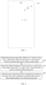
- FIG. 1 is a block diagram of a mobile terminal 100 shown as an example of the present invention.
- the mobile terminal 100 includes a display screen 120 and an ambient light sensor 160 located in a first area 140 of the display screen 120 (or below the first area 140).
- the mobile terminal 100 may be or may not be a terminal with a full screen design.
- FIG. 1 illustrates the mobile terminal 100 by using a full screen design.
- the full screen refers to a design that all area (or most of the area) except a bezel 180 on a front panel is provided with the display screen 120.
- the first area 140 is formed on the display screen 120.
- the first area 140 may be a hole area or a light transmitting area.
- the ambient light sensor 160 is disposed in the first area 140 or below the first area 140.
- the ambient light sensor 160 is disposed below the light transmitting area.
- FIG. 2 is a flowchart of an ambient light collecting method according to some embodiments of the present application.
- the method may be applied to a terminal 100 provided with an ambient light sensor 160.
- the ambient light sensor 160 is disposed in a first area 140 of a display screen 120 of the terminal 100.
- the method includes the following steps.
- a target image frame adjacent to a collection time point is determined.
- the collection time point is a time point at which the ambient light sensor collects ambient light.
- the display screen 120 displays an image frame at a certain frequency, such as displaying 60 frames per second.
- a certain frequency such as displaying 60 frames per second.
- the collection time point is the time at which the ambient light sensor 160 collects ambient light. When the image frame is displayed on the display screen 120, it will affect the ambient light sensor 160 to collect ambient light. As an example, the collection time point is provided in a display interval between two adjacent image frames (the i-th frame image frame and the i-th frame image frame).
- the terminal 100 determines at least one image frame adjacent to the collection time point as the target image frame.
- step 204 display brightness of pixel points in a second area of the target image frame is decreased to a target value.
- the first area 140 is a sub-area of the second area.
- the second area is an area on the target image frame that covers (or partially covers) the first area 140. That is, the first area 140 is a sub-area of the second area.
- the terminal 100 decreases the display brightness of the pixel points in the second area of the target image frame to a target value.
- the target value is a preset value or a dynamically determined value.
- step 206 the target image frame is displayed according to the target value, and the ambient light sensor 160 is controlled to collect ambient light at the collection time point.
- the terminal 100 displays the target image frame at a certain frequency, and controls the ambient light sensor 160 to collect ambient light at the collection time point.
- the order of the time of displaying the target image frame and the collection time point is not limited.
- the time of displaying the target image frame is located before the collection time point, or may be located before and after the collection time point.
- the display brightness of the pixel points in the second area can be decreased as much as possible, thereby reducing or eliminating the influence of the display light emitted by the pixel points in the second area on the ambient light sensor when collecting ambient light.
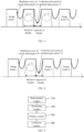
- a collection time point 32 of the ambient light sensor 160 is provided in a display interval between two adjacent image frames (an image frame 2 and an image frame 3).
- the terminal 100 determines the image frame 2 and the image frame 3 as target image frames adjacent to the collection time point 32. For pixel points in a second area 34 on the image frame 2 and the image frame 3, the terminal 100 can decrease the display brightness of these pixel points to the target value. In this way, the illumination brightness of the pixel points in the second area 34 is lowered, and the screen illumination brightness at the collection time point 32 is lower than the screen illumination brightness in a display interval between other image frames (such as the screen illumination brightness between an image frame 1 and the image frame 2).
- the terminal 100 determines a target image frame adjacent to a collection time point in at least one of the following manners.
- a previous frame adjacent to the collection time point is determined as the target image frame.
- the previous frame (the image frame 2) adjacent to the collection time point is determined as the target image frame.
- the previous frame and a subsequent frame adjacent to the collection time point are determined as target image frames.
- the first n frames adjacent to the collection time point are determined as target image frames.
- N is an integer greater than 1.
- the first 2 frames adjacent to the collection time point are determined as target image frames, or the first 5 frames adjacent to the collection time point are determined as target image frames.
- the first n frames and the last m frames adjacent to the collection time point are determined as target image frames.
- n and m are integers greater than 1.
- the preceding 2 frames and the subsequent 2 frames adjacent to the collection time point are determined as target image frames, or the preceding 3 frames and the subsequent frame adjacent to the collection time point are determined as target image frames.
- the terminal can determine the target image frame in any one of the above four manners according to its own hardware performance or usage scenario.
- step 202 may be implemented in at least one of the following implementation manners:
- the first target value is a static value set when leaving the factory, or set by server update, or manually set by a user.
- the second manner dynamic adjustment based on the time period;
- the terminal 100 acquires a time period corresponding to the current time; determines a second target value corresponding to the time period; and determines the display brightness of the pixel points in the second area of the target image frame as the second target value.
- the terminal 100 can invoke a time interface in the operating system to acquire time in the operating system.
- the terminal 100 stores a first corresponding relationship between the time period and the second target value. For example, a second target value of the daytime period is higher than a second target value of the nighttime period. The terminal 100 dynamically determines the second target value according to the time period in which the current time is located.
- Table 1 schematically shows the first corresponding relationship.
- Table 1 Time period Second target value 8:00am to 3:00pm Brightness 1 3:00pm to 8:00pm Brightness 2 8:00pm to 8:00am Brightness 3
- the third manner dynamical adjustment based on the display type;
- the terminal determines a display type of the target image frame, which can include any one of a user interface, a video frame, or an electronic document; determines a third target value corresponding to the display type; and determines the display brightness of the pixel points in the second area of the target image frame as the third target value.
- the terminal 100 can invoke a task stack in the operating system to determine a display type of the front-end user interface according to the task stack.
- the third target value can be as low as possible.
- the third target value can be slightly higher.
- Table 2 schematically shows the second corresponding relationship. Table 2 Time period Second target value User interface Brightness 1 Video frame Brightness 2 Electronic document Brightness 3
- the fourth manner dynamical adjustment based on the hue type
- the terminal 100 determines a hue type of the target image frame; determines a fourth target value corresponding to the hue type; and determines the display brightness of the pixel points in the second area of the target image frame as the fourth target value.
- the terminal 100 calculates an overall average color value of the target image frame, and determine a hue type of the target image frame according to the overall average color value. For a dark hue type, a relatively lower fourth target value (dark) is determined. For a light hue type, a relatively higher fourth target value (bright) is determined.
- the methods according to the present invention provide a better balance between improving the ambient light collection accuracy and ensuring a better display effect by dynamically determining the target value.
- the shape and size of the second area described above are not limited.
- the second area may be a statically invariable area or a dynamically changed area.
- the terminal 100 determines the shape of a preset area as the shape of the second area.
- the preset area includes at least one of a rectangle, a square, a circle, or a hexagon.
- the terminal 100 determines a shape of a display element that has an intersection with the first area of the target image frame.
- the display element can include at least one of a control element, a moving object, a character, or a pattern.
- the display element is determined as the shape of the second area.
- the image frame is a user interface
- the position of the control element (such as a button) at the first area is determined as the second area.
- the image frame is a video frame, and a bird in the video frame is located in the first area 140, then the bird-shaped area where the bird is located is determined as the second area. In this way, a better display effect can be retained.
- FIG. 5 shows a block diagram of an ambient light collecting apparatus shown in example of the present invention.
- the ambient light sensor 160 is disposed in a first area 140 in a display screen 120 of the terminal 100.
- the apparatus includes:
- portions may have modular configurations, or are composed of discrete components, but nonetheless can be referred to as “portions” in general.
- portions in general.
- the "components,” “portions,” “blocks,” “portions,” or “portions” referred to herein may or may not be in modular forms.
- the decreasing module 540 is configured to acquire a preset first target value, and to determine the display brightness of the pixel points in the second area of the target image frame as the first target value.
- the decreasing module 540 is configured to acquire a time period corresponding to the current time, to determine a second target value corresponding to the time period, and to determine the display brightness of the pixel points in the second area of the target image frame as the second target value.
- the decreasing module 540 is configured to determine a display type of the target image frame, which can include at least one of a user interface, a video frame, or an electronic document; to determine a third target value corresponding to the display type; and to determine the display brightness of the pixel points in the second area of the target image frame as the third target value.
- the decreasing module 540 is configured to determine a hue type of the target image frame; to determine a fourth target value corresponding to the hue type; and to determine the display brightness of the pixel points in the second area of the target image frame as the fourth target value.
- the determination module 520 is configured to determine a previous frame adjacent to the collection time point as the target image frame; or the determination module 520 is configured to determine the previous frame and a subsequent frame adjacent to the collection time point as the target image frames; or the determination module 520 is configured to determine the preceding n frames adjacent to the collection time point as the target image frames, where n is an integer greater than 1; or the determination module 520 is configured to determine the preceding n frames and the subsequent m frames adjacent to the collection time point as the target image frames, where n and m are integers greater than 1.
- the collection time point is located in a display interval of two adjacent image frames.
- the determination module 520 is further configured to determine a shape of a preset area as the shape of the second area, where the preset area can include at least any one of a rectangle, a square, a circle or a hexagon.
- the determination module 520 is further configured to determine a shape of a display element of the target image frame that has an intersection with the first area, where the display element can include at least one of a control element, a moving object, a character, or a pattern; and to determine the display element as the shape of the second area.
- FIG. 6 is a block diagram of an ambient light collecting apparatus 600 in accordance with an example of the present invention.
- the apparatus 600 may be a mobile phone, a computer, a digital broadcast terminal, a messaging device, a gaming console, a tablet device, a medical device, a fitness equipment, a personal digital assistant, and the like.
- the apparatus 600 may include one or more of the following components: a processing component 602, a memory 604, a power component 606, a multimedia component 608, an audio component 610, an input/output (I/O) interface 612, a sensor component 614, and a communication component 616.
- a processing component 602 a memory 604, a power component 606, a multimedia component 608, an audio component 610, an input/output (I/O) interface 612, a sensor component 614, and a communication component 616.
- the processing component 602 typically controls the overall operations of the apparatus 600, such as the operations associated with display, telephone calls, data communications, camera operations, and recording operations.
- the processing component 602 includes one or more processors 620 to execute instructions to perform all or part of the steps in the above described methods.
- the processing component 602 may include one or more modules which facilitate the interaction between the processing component 602 and other components.
- the processing component 602 may include a multimedia module to facilitate the interaction between the multimedia component 608 and the processing component 602.
- the memory 604 is configured to store various types of data to support the operation of the apparatus 600. Examples of such data include instructions for any applications or methods operated on the apparatus 600, contact data, phonebook data, messages, pictures, videos, etc.
- the memory 604 may be implemented by using any type of volatile or non-volatile memory devices, or a combination thereof, such as a static random access memory (SRAM), an electrically erasable programmable read-only memory (EEPROM), an erasable programmable read-only memory (EPROM), a programmable read-only memory (PROM), a read-only memory (ROM), a magnetic memory, a flash memory, a magnetic or optical disk.
- SRAM static random access memory
- EEPROM electrically erasable programmable read-only memory
- EPROM erasable programmable read-only memory
- PROM programmable read-only memory
- ROM read-only memory
- magnetic memory a magnetic memory
- flash memory a flash memory
- magnetic or optical disk a magnetic or
- the power component 606 provides power to various components of the apparatus 600.
- the power component 606 may include a power management system, one or more power sources, and any other components associated with the generation, management, and distribution of power in the apparatus 600.
- the multimedia component 608 includes a screen providing an output interface between the apparatus 600 and the user.
- the screen may include a liquid crystal display (LCD) and a touch panel (TP).
- LCD liquid crystal display
- TP touch panel
- OLED organic light-emitting diode
- the screen may be implemented as a touch screen to receive input signals from the user.
- the touch panel includes one or more touch sensors to sense touches, swipes, and gestures on the touch panel. The touch sensors may not only sense a boundary of a touch or swipe action, but also sense the duration and pressure associated with the touch or swipe action.
- the multimedia component 608 includes a front camera and/or a rear camera.
- the front camera and the rear camera may receive external multimedia data while the apparatus 600 is in an operation mode, such as a photographing mode or a video mode.
- Each of the front camera and the rear camera may be a fixed optical lens system or have focus and optical zoom capability.
- the audio component 610 is configured to output and/or input audio signals.
- the audio component 610 includes a microphone (MIC) configured to receive external audio signals when the apparatus 600 is in an operation mode, such as a call mode, a recording mode, and a voice recognition mode.
- the received audio signal may be further stored in the memory 604 or transmitted via the communication component 616.
- the audio component 610 further includes a speaker for outputting audio signals.
- the I/O interface 612 provides an interface between the processing component 602 and peripheral interface modules, such as a keyboard, a click wheel, buttons, and the like.
- the buttons may include, but are not limited to, a home button, a volume button, a start button, and a lock button.
- the sensor component 614 includes one or more sensors to provide status assessments of various aspects of the apparatus 600. For instance, the sensor component 614 may detect an on/off status of the apparatus 600, relative positioning of components, e.g., the display device and the mini keyboard of the apparatus 600, and the sensor component 614 may also detect a position change of the apparatus 600 or a component of the apparatus 600, presence or absence of user contact with the apparatus 600, orientation or acceleration/deceleration of the apparatus 600, and temperature change of the apparatus 600.
- the sensor component 614 may include a proximity sensor configured to detect the presence of nearby objects without any physical contact.
- the sensor component 614 may also include a light sensor, such as a CMOS or CCD image sensor, used for imaging applications.
- the sensor component 614 may also include an accelerometer sensor, a gyroscope sensor, a magnetic sensor, a pressure sensor, or a temperature sensor.
- the communication component 616 is configured to facilitate communication, wired or wirelessly, between the apparatus 600 and other devices.
- the apparatus 600 can access a wireless network based on a communication standard, such as Wi-Fi, 2G, 3G, 4G, or 5G, or a combination thereof.
- the communication component 616 receives broadcast signals or broadcast associated information from an external broadcast management system via a broadcast channel.
- the communication component 616 further includes a near field communication (NFC) module to facilitate short-range communications.
- NFC near field communication
- the apparatus 600 may be implemented with one or more application specific integrated circuits (ASICs), digital signal processors (DSPs), digital signal processing devices (DSPDs), programmable logic devices (PLDs), field programmable gate arrays (FPGAs), controllers, micro-controllers, microprocessors, or other electronic components, for performing the above described methods.
- ASICs application specific integrated circuits
- DSPs digital signal processors
- DSPDs digital signal processing devices
- PLDs programmable logic devices
- FPGAs field programmable gate arrays
- controllers micro-controllers, microprocessors, or other electronic components, for performing the above described methods.
- a non-transitory computer-readable storage medium including instructions is also provided, such as-the memory 604 including instructions, executable by the processor 620 in the apparatus 600, for performing the above-described methods.
- the non-transitory computer-readable storage medium may be a ROM, a RAM, a CD-ROM, a magnetic tape, a floppy disc, an optical data storage device, and the like.
- the present invention can have one or more of the following advantages.
- the display brightness of the pixel points in the second area can be decreased as much as possible, thereby reducing or eliminating the influence of the display light emitted by the pixel points in the second area on the ambient light sensor when collecting ambient light.
- the terms “one embodiment,” “implementation,” “some embodiments,” “example,” “specific example,” or “some examples,” and the like can indicate a specific feature described in connection with the embodiment or example, a structure, a material or feature included in at least one embodiment or example.
- the schematic representation of the above terms is not necessarily directed to the same embodiment or example.
- control and/or interface software or app can be provided in a form of a non-transitory computer-readable storage medium having instructions stored thereon.
- the non-transitory computer-readable storage medium can be a ROM, a CD-ROM, a magnetic tape, a floppy disk, optical data storage equipment, a flash drive such as a USB drive or an SD card, and the like.
- Implementations of the subject matter and the operations described in this invention can be implemented in digital electronic circuitry, or in computer software, firmware, or hardware, including the structures disclosed herein and their structural equivalents, or in combinations of one or more of them. Implementations of the subject matter described in this invention can be implemented as one or more computer programs, i.e., one or more portions of computer program instructions, encoded on one or more computer storage medium for execution by, or to control the operation of, data processing apparatus.
- the program instructions can be encoded on an artificially-generated propagated signal, e.g., a machine-generated electrical, optical, or electromagnetic signal, which is generated to encode information for transmission to suitable receiver apparatus for execution by a data processing apparatus.
- an artificially-generated propagated signal e.g., a machine-generated electrical, optical, or electromagnetic signal, which is generated to encode information for transmission to suitable receiver apparatus for execution by a data processing apparatus.
- a computer storage medium can be, or be included in, a computer-readable storage device, a computer-readable storage substrate, a random or serial access memory array or device, or a combination of one or more of them.
- a computer storage medium is not a propagated signal
- a computer storage medium can be a source or destination of computer program instructions encoded in an artificially-generated propagated signal.
- the computer storage medium can also be, or be included in, one or more separate components or media (e.g., multiple CDs, disks, drives, or other storage devices). Accordingly, the computer storage medium can be tangible.
- the operations described in this invention can be implemented as operations performed by a data processing apparatus on data stored on one or more computer-readable storage devices or received from other sources.
- the devices in this invention can include special purpose logic circuitry, e.g., an FPGA (field-programmable gate array), or an ASIC (application-specific integrated circuit).
- the device can also include, in addition to hardware, code that creates an execution environment for the computer program in question, e.g., code that constitutes processor firmware, a protocol stack, a database management system, an operating system, a cross-platform runtime environment, a virtual machine, or a combination of one or more of them.
- the devices and execution environment can realize various different computing model infrastructures, such as web services, distributed computing, and grid computing infrastructures.
- a computer program (also known as a program, software, software application, app, script, or code) can be written in any form of programming language, including compiled or interpreted languages, declarative or procedural languages, and it can be deployed in any form, including as a stand-alone program or as a portion, component, subroutine, object, or other portion suitable for use in a computing environment.
- a computer program can, but need not, correspond to a file in a file system.
- a program can be stored in a portion of a file that holds other programs or data (e.g., one or more scripts stored in a markup language document), in a single file dedicated to the program in question, or in multiple coordinated files (e.g., files that store one or more portions, sub-programs, or portions of code).
- a computer program can be deployed to be executed on one computer or on multiple computers that are located at one site or distributed across multiple sites and interconnected by a communication network.
- the processes and logic flows described in this invention can be performed by one or more programmable processors executing one or more computer programs to perform actions by operating on input data and generating output.
- the processes and logic flows can also be performed by, and apparatus can also be implemented as, special purpose logic circuitry, e.g., an FPGA, or an ASIC.
- processors or processing circuits suitable for the execution of a computer program include, by way of example, both general and special purpose microprocessors, and any one or more processors of any kind of digital computer.
- a processor will receive instructions and data from a read-only memory, or a random-access memory, or both.
- Elements of a computer can include a processor configured to perform actions in accordance with instructions and one or more memory devices for storing instructions and data.
- a computer will also include, or be operatively coupled to receive data from or transfer data to, or both, one or more mass storage devices for storing data, e.g., magnetic, magneto-optical disks, or optical disks.
- mass storage devices for storing data
- a computer need not have such devices.
- a computer can be embedded in another device, e.g., a mobile telephone, a personal digital assistant (PDA), a mobile audio or video player, a game console, a Global Positioning System (GPS) receiver, or a portable storage device (e.g., a universal serial bus (USB) flash drive), to name just a few.
- PDA personal digital assistant
- GPS Global Positioning System
- USB universal serial bus
- Devices suitable for storing computer program instructions and data include all forms of non-volatile memory, media and memory devices, including by way of example semiconductor memory devices, e.g., EPROM, EEPROM, and flash memory devices; magnetic disks, e.g., internal hard disks or removable disks; magneto-optical disks; and CD-ROM and DVD-ROM disks.
- semiconductor memory devices e.g., EPROM, EEPROM, and flash memory devices
- magnetic disks e.g., internal hard disks or removable disks
- magneto-optical disks e.g., CD-ROM and DVD-ROM disks.
- the processor and the memory can be supplemented by, or incorporated in, special purpose logic circuitry.
- implementations of the subject matter described in this specification can be implemented with a computer and/or a display device, e.g., a VR/AR device, a head-mount display (HMD) device, a head-up display (HUD) device, smart eyewear (e.g., glasses), a CRT (cathode-ray tube), LCD (liquid-crystal display), OLED (organic light emitting diode), or any other monitor for displaying information to the user and a keyboard, a pointing device, e.g., a mouse, trackball, etc., or a touch screen, touch pad, etc., by which the user can provide input to the computer.
- a display device e.g., a VR/AR device, a head-mount display (HMD) device, a head-up display (HUD) device, smart eyewear (e.g., glasses), a CRT (cathode-ray tube), LCD (liquid-crystal display), OLED (organic light emitting dio
- Implementations of the subject matter described in this specification can be implemented in a computing system that includes a back-end component, e.g., as a data server, or that includes a middleware component, e.g., an application server, or that includes a front-end component, e.g., a client computer having a graphical user interface or a Web browser through which a user can interact with an implementation of the subject matter described in this specification, or any combination of one or more such back-end, middleware, or front-end components.
- a back-end component e.g., as a data server
- a middleware component e.g., an application server
- a front-end component e.g., a client computer having a graphical user interface or a Web browser through which a user can interact with an implementation of the subject matter described in this specification, or any combination of one or more such back-end, middleware, or front-end components.
- the components of the system can be interconnected by any form or medium of digital data communication, e.g., a communication network.
- communication networks include a local area network ("LAN”) and a wide area network (“WAN”), an inter-network (e.g., the Internet), and peer-to-peer networks (e.g., ad hoc peer-to-peer networks).
- LAN local area network
- WAN wide area network
- Internet inter-network
- peer-to-peer networks e.g., ad hoc peer-to-peer networks.
Landscapes
- Engineering & Computer Science (AREA)
- Physics & Mathematics (AREA)
- Computer Hardware Design (AREA)
- General Physics & Mathematics (AREA)
- Theoretical Computer Science (AREA)
- Environmental & Geological Engineering (AREA)
- Human Computer Interaction (AREA)
- Computer Networks & Wireless Communication (AREA)
- Signal Processing (AREA)
- Chemical & Material Sciences (AREA)
- Crystallography & Structural Chemistry (AREA)
- Controls And Circuits For Display Device (AREA)
Claims (7)
- Verfahren zum Sammeln von Umgebungslicht, das bei einem Endgerät (100) eingesetzt wird, das mit einem Umgebungslichtsensor (160) in einem ersten Bereich (140) in einem Anzeigebildschirm (120) des Endgeräts (100) versehen ist, wobei das Verfahren umfasst:Bestimmen (202) eines Ziel-Einzelbildes, wobei das Ziel-Einzelbild ein anzuzeigendes Einzelbild ist, angrenzend an einen Sammelzeitpunkt, wobei der Sammelzeitpunkt ein Zeitpunkt ist, der in einem Anzeigeintervall zwischen zwei angrenzenden Einzelbildern vorgesehen ist und zu dem der Umgebungslichtsensor (160) Umgebungslicht sammelt, und wobei das Ziel-Einzelbild das angrenzende Einzelbild umfasst, das vor dem Sammelzeitpunkt angezeigt werden soll;Verringern (204) der Anzeigehelligkeit von Pixelpunkten in einem zweiten Bereich des Ziel-Einzelbildes auf einen Zielwert, wobei der Zielwert gemäß mindestens einem der folgenden Schritte bestimmt wird:Erfassen der aktuellen Tageszeit von dem Betriebssystem des Endgeräts und Bestimmen des Zielwerts basierend auf einer vorgespeicherten Korrespondenzbeziehung zwischen Tageszeit und Zielwerten;Berechnen eines durchschnittlichen Gesamtfarbwerts des Ziel-Einzelbildes als eine Farbtonart, und Bestimmen eines relativ niedrigeren Werts als Ziel für eine dunkle Farbtonart, oder Bestimmen eines relativ höheren Werts als Zielwert für eine helle Farbtonart;Aufrufen eines Aufgabenstapels in dem Betriebssystem zum Bestimmen einer Anzeigeart einer Frontend-Benutzeroberfläche gemäß dem Aufgabenstapel, und Bestimmen des Zielwerts basierend auf einer vorgespeicherten Korrespondenzbeziehung zwischen der Anzeigeart und den Zielwerten, wobei die Anzeigeart mindestens eines aus einer Benutzeroberfläche, einem Videoeinzelbild, oder einem elektronischen Dokument umfasst;wobei der erste Bereich (140) ein Subbereich des zweiten Bereichs ist; undAnzeigen (206) des Ziel-Einzelbildes gemäß dem Zielwert, und Steuern des Umgebungslichtsensors (160), um das Umgebungslicht zu dem Sammelzeitpunkt zu sammeln.
- Verfahren nach Anspruch 1, wobei das Bestimmen (202) eines Ziel-Einzelbildes angrenzend an einen Sammelzeitpunkt umfasst:
Bestimmen eines vorherigen Einzelbildes direkt angrenzend an den Sammelzeitpunkt als Ziel-Einzelbild. - Verfahren nach Anspruch 1, wobei das Bestimmen (202) eines Ziel-Einzelbildes angrenzend an einen Sammelzeitpunkt umfasst:
Bestimmen des vorherigen Einzelbildes und eines nachfolgenden Einzelbildes angrenzend an den Sammelzeitpunkt als Ziel-Einzelbilder. - Verfahren nach Anspruch 1, wobei das Bestimmen (202) eines Ziel-Einzelbildes angrenzend an einen Sammelzeitpunkt umfasst:
Bestimmen von ersten n Einzelbildern angrenzend an den Sammelzeitpunkt als Ziel-Einzelbilder, wobei n eine ganze Zahl größer als 1 ist. - Verfahren nach Anspruch 1, wobei das Bestimmen (202) eines Ziel-Einzelbildes angrenzend an einen Sammelzeitpunkt umfasst:
Bestimmen der ersten n Einzelbilder und der letzten m Einzelbilder angrenzend an den Sammelzeitpunkt als Ziel-Einzelbilder, wobei n und m ganze Zahlen größer als 1 sind. - Verfahren nach einem der Ansprüche 1 bis 5, das ferner umfasst:
Bestimmen einer Form eines vorbestimmten Bereichs als eine Form des zweiten Bereichs, wobei der vorbestimmte Bereich mindestens eines aus einem Rechteck, einem Quadrat, einem Kreis, oder einem Hexagon umfasst. - Endgerät (100), das aufweist: einen Prozessor (620), einen Speicher (604), und einen Umgebungslichtsensor (160) in einem ersten Bereich (140) in einem Anzeigebildschirm (120) des Endgeräts (100), wobei ein Computerprogramm in dem Speicher (604) gespeichert ist und von dem Prozessor (620) ausgeführt wird, um das Verfahren nach einem der Ansprüche 1 bis 6 auszuführen.
Applications Claiming Priority (1)
| Application Number | Priority Date | Filing Date | Title |
|---|---|---|---|
| CN201910611827.9A CN112201211B (zh) | 2019-07-08 | 2019-07-08 | 环境光采集方法、装置、终端及存储介质 |
Publications (2)
| Publication Number | Publication Date |
|---|---|
| EP3764345A1 EP3764345A1 (de) | 2021-01-13 |
| EP3764345B1 true EP3764345B1 (de) | 2024-11-06 |
Family
ID=69571789
Family Applications (1)
| Application Number | Title | Priority Date | Filing Date |
|---|---|---|---|
| EP20156548.8A Active EP3764345B1 (de) | 2019-07-08 | 2020-02-11 | Verfahren umgebungslicht zu detektieren, endgerät und speichermedium |
Country Status (3)
| Country | Link |
|---|---|
| US (1) | US11227533B2 (de) |
| EP (1) | EP3764345B1 (de) |
| CN (1) | CN112201211B (de) |
Families Citing this family (5)
| Publication number | Priority date | Publication date | Assignee | Title |
|---|---|---|---|---|
| JP2021057737A (ja) * | 2019-09-30 | 2021-04-08 | セイコーエプソン株式会社 | 表示システム、表示制御方法、および、プログラム |
| CN114360420B (zh) * | 2020-10-13 | 2024-05-10 | 明基智能科技(上海)有限公司 | 显示装置的影像调整方法及显示装置 |
| CN112949556B (zh) * | 2021-03-23 | 2023-07-25 | 北京市商汤科技开发有限公司 | 光强控制方法及装置、电子设备和存储介质 |
| CN114461093B (zh) * | 2021-08-19 | 2023-01-20 | 荣耀终端有限公司 | 一种环境光的检测方法、电子设备、芯片系统及存储介质 |
| CN115460732B (zh) * | 2022-11-11 | 2023-03-24 | 深圳市爱图仕影像器材有限公司 | 灯光设备控制方法、装置、终端设备及存储介质 |
Citations (1)
| Publication number | Priority date | Publication date | Assignee | Title |
|---|---|---|---|---|
| US20200342800A1 (en) * | 2017-12-29 | 2020-10-29 | Huawei Technologies Co., Ltd. | Ambient light and proximity detection method, photographing method, and terminal |
Family Cites Families (45)
| Publication number | Priority date | Publication date | Assignee | Title |
|---|---|---|---|---|
| US6271813B1 (en) * | 1996-08-30 | 2001-08-07 | Lear Automotive Dearborn, Inc. | Voltage control for adjusting the brightness of a screen display |
| US6762741B2 (en) * | 2000-12-22 | 2004-07-13 | Visteon Global Technologies, Inc. | Automatic brightness control system and method for a display device using a logarithmic sensor |
| US6592232B2 (en) * | 2001-11-16 | 2003-07-15 | Intel Corporation | Augmented backlight |
| JP4628770B2 (ja) * | 2004-02-09 | 2011-02-09 | 株式会社日立製作所 | 照明装置を備えた画像表示装置及び画像表示方法 |
| US20060132400A1 (en) * | 2004-12-20 | 2006-06-22 | Eastman Kodak Company | Ambient light detection using an OLED device |
| JP4338140B2 (ja) * | 2005-05-12 | 2009-10-07 | 株式会社 日立ディスプレイズ | タッチパネル一体表示装置 |
| KR100762677B1 (ko) * | 2005-08-08 | 2007-10-01 | 삼성에스디아이 주식회사 | 유기 발광 표시장치 및 그 제어 방법 |
| JP2007241358A (ja) * | 2006-03-06 | 2007-09-20 | Hitachi Displays Ltd | 画像表示装置 |
| US8872753B2 (en) * | 2006-08-31 | 2014-10-28 | Ati Technologies Ulc | Adjusting brightness of a display image in a display having an adjustable intensity light source |
| US8698727B2 (en) * | 2007-01-05 | 2014-04-15 | Apple Inc. | Backlight and ambient light sensor system |
| JP4661875B2 (ja) * | 2008-01-15 | 2011-03-30 | ソニー株式会社 | 表示装置及び表示装置の輝度調整方法 |
| US8344998B2 (en) * | 2008-02-01 | 2013-01-01 | Wimm Labs, Inc. | Gesture-based power management of a wearable portable electronic device with display |
| JP4582166B2 (ja) * | 2008-03-19 | 2010-11-17 | ソニー株式会社 | 表示装置 |
| WO2010035473A1 (ja) * | 2008-09-29 | 2010-04-01 | パナソニック株式会社 | バックライト装置および表示装置 |
| CN101789230B (zh) * | 2009-01-24 | 2013-09-04 | 联想(北京)有限公司 | 一种电子设备及该设备显示器件的屏幕亮度的调整方法 |
| JP4699536B2 (ja) * | 2009-03-06 | 2011-06-15 | シャープ株式会社 | 位置検出装置、制御方法、制御プログラムおよび記録媒体 |
| GB2473639A (en) * | 2009-09-18 | 2011-03-23 | Litelogic Ip Ltd | Display with multiple PCBs mounted to bus-bars |
| JP2014071372A (ja) * | 2012-09-28 | 2014-04-21 | Japan Display Inc | 表示装置および電子機器 |
| US9024530B2 (en) * | 2012-11-13 | 2015-05-05 | Apple Inc. | Synchronized ambient light sensor and display |
| US8987652B2 (en) * | 2012-12-13 | 2015-03-24 | Apple Inc. | Electronic device with display and low-noise ambient light sensor with a control circuitry that periodically disables the display |
| US9345103B1 (en) * | 2013-01-07 | 2016-05-17 | Amazon Technologies, Inc. | Non-linear lighting system brightness control for a user device |
| US9536325B2 (en) * | 2013-06-09 | 2017-01-03 | Apple Inc. | Night mode |
| CN104240678B (zh) * | 2013-06-17 | 2017-12-29 | 华为终端(东莞)有限公司 | 调整屏幕背光亮度的方法和装置以及终端 |
| CN104376835B (zh) * | 2013-08-16 | 2017-02-08 | 联想(北京)有限公司 | 一种调整亮度的方法及电子设备 |
| US9530342B2 (en) * | 2013-09-10 | 2016-12-27 | Microsoft Technology Licensing, Llc | Ambient light context-aware display |
| US10165217B2 (en) * | 2014-08-28 | 2018-12-25 | Hisense Electric Co., Ltd. | Backlight source control method of display device, display device and storage medium |
| US9911395B1 (en) * | 2014-12-23 | 2018-03-06 | Amazon Technologies, Inc. | Glare correction via pixel processing |
| US9564104B1 (en) * | 2015-05-18 | 2017-02-07 | Amazon Technologies, Inc. | Adjusting front light brightness during display updates |
| CN107004130B (zh) * | 2015-06-18 | 2020-08-28 | 深圳市汇顶科技股份有限公司 | 用于屏幕上指纹感应的屏幕下光学传感器模块 |
| US10140909B2 (en) * | 2015-09-14 | 2018-11-27 | Japan Display Inc. | Display device |
| CN106993176A (zh) * | 2016-01-20 | 2017-07-28 | 掌赢信息科技(上海)有限公司 | 一种调节视频亮度的方法和电子设备 |
| US10545242B2 (en) * | 2016-09-14 | 2020-01-28 | Apple Inc. | Systems and methods for in-frame sensing and adaptive sensing control |
| US20180075798A1 (en) * | 2016-09-14 | 2018-03-15 | Apple Inc. | External Compensation for Display on Mobile Device |
| KR102567543B1 (ko) * | 2017-01-06 | 2023-08-21 | 삼성전자 주식회사 | 전자 장치 및 생체 센서를 위한 디스플레이 제어 방법 |
| US10614283B2 (en) * | 2017-03-07 | 2020-04-07 | Shenzhen GOODIX Technology Co., Ltd. | Devices with peripheral task bar display zone and under-LCD screen optical sensor module for on-screen fingerprint sensing |
| US10564774B1 (en) * | 2017-04-07 | 2020-02-18 | Apple Inc. | Correction schemes for display panel sensing |
| CN107665698B (zh) * | 2017-11-13 | 2020-01-03 | 维沃移动通信有限公司 | 环境光强度补偿方法及装置 |
| CN107945754A (zh) * | 2017-11-20 | 2018-04-20 | 上海与德科技有限公司 | 屏幕亮度的调节方法、电子设备及计算机可读存储介质 |
| CN107979698B (zh) * | 2017-11-22 | 2020-05-12 | Oppo广东移动通信有限公司 | 环境光强度检测方法、装置、存储介质及电子设备 |
| CN107818753A (zh) * | 2017-11-22 | 2018-03-20 | 广东欧珀移动通信有限公司 | 屏幕亮度调整方法、装置、存储介质和电子设备 |
| CN107990978A (zh) * | 2017-11-22 | 2018-05-04 | 广东欧珀移动通信有限公司 | 环境光检测方法、装置、存储介质及电子设备 |
| CN108269538B (zh) * | 2017-12-21 | 2020-08-11 | 惠科股份有限公司 | 显示装置的驱动方法及其驱动装置 |
| CN108182896B (zh) * | 2017-12-25 | 2019-08-20 | 维沃移动通信有限公司 | 一种亮度检测方法、装置及移动终端 |
| CN108461060A (zh) | 2018-04-08 | 2018-08-28 | 北京小米移动软件有限公司 | 显示面板、光电检测方法、装置及计算机可读存储介质 |
| CN109036331B (zh) * | 2018-08-24 | 2020-04-24 | 京东方科技集团股份有限公司 | 显示屏的亮度调节方法及装置、显示屏 |
-
2019
- 2019-07-08 CN CN201910611827.9A patent/CN112201211B/zh active Active
- 2019-11-17 US US16/686,147 patent/US11227533B2/en active Active
-
2020
- 2020-02-11 EP EP20156548.8A patent/EP3764345B1/de active Active
Patent Citations (1)
| Publication number | Priority date | Publication date | Assignee | Title |
|---|---|---|---|---|
| US20200342800A1 (en) * | 2017-12-29 | 2020-10-29 | Huawei Technologies Co., Ltd. | Ambient light and proximity detection method, photographing method, and terminal |
Also Published As
| Publication number | Publication date |
|---|---|
| EP3764345A1 (de) | 2021-01-13 |
| CN112201211B (zh) | 2022-04-29 |
| US20210012702A1 (en) | 2021-01-14 |
| US11227533B2 (en) | 2022-01-18 |
| CN112201211A (zh) | 2021-01-08 |
Similar Documents
| Publication | Publication Date | Title |
|---|---|---|
| US11227533B2 (en) | Ambient light collecting method and apparatus, terminal and storage medium | |
| US11205369B2 (en) | Screen display method and apparatus, and method and apparatus for generating grayscale mapping information | |
| US10997928B1 (en) | Method, apparatus and storage medium for determining ambient light intensity | |
| US11503207B2 (en) | Display control method, display control device and computer-readable storage medium | |
| US10694291B2 (en) | Directional propagation method and apparatus for audio signal, a terminal device and a storage medium | |
| EP3496085B1 (de) | Verfahren und vorrichtung zur steuerung der helligkeit einer hintergrundbeleuchtung | |
| US10672851B2 (en) | Display panel and photoelectric detection method | |
| US10269287B2 (en) | Power saving method and device for displaying content in display screen | |
| US20170154604A1 (en) | Method and apparatus for adjusting luminance | |
| US20210335287A1 (en) | Screen display adjusting method, apparatus and storage medium | |
| KR20170125604A (ko) | 전자 장치 및 그 제어 방법 | |
| EP3916707A1 (de) | Verfahren und vorrichtung zur steuerung der bildwiederholrate eines bildschirms | |
| US11094291B2 (en) | Method and device for detecting ambient light and terminal | |
| CN111754929B (zh) | 环境光参数采集方法、装置及存储介质 | |
| US10134326B2 (en) | Device for and method of saving power when refreshing a display screen when displayed content does not change | |
| US11295505B2 (en) | Animation generation using a target animation model and animation state parameters | |
| EP3425533A1 (de) | Seite anzeigen | |
| US10930217B2 (en) | Method and apparatus for compensating operating parameter of display circuit | |
| US20220038619A1 (en) | Take-off capture method and electronic device, and storage medium | |
| US9947278B2 (en) | Display method and device and computer-readable medium | |
| CN114637390A (zh) | 内容显示方法及装置 | |
| CN117195327A (zh) | 显示控制方法、装置、电子设备及存储介质 |
Legal Events
| Date | Code | Title | Description |
|---|---|---|---|
| PUAI | Public reference made under article 153(3) epc to a published international application that has entered the european phase |
Free format text: ORIGINAL CODE: 0009012 |
|
| STAA | Information on the status of an ep patent application or granted ep patent |
Free format text: STATUS: THE APPLICATION HAS BEEN PUBLISHED |
|
| AK | Designated contracting states |
Kind code of ref document: A1 Designated state(s): AL AT BE BG CH CY CZ DE DK EE ES FI FR GB GR HR HU IE IS IT LI LT LU LV MC MK MT NL NO PL PT RO RS SE SI SK SM TR |
|
| AX | Request for extension of the european patent |
Extension state: BA ME |
|
| STAA | Information on the status of an ep patent application or granted ep patent |
Free format text: STATUS: REQUEST FOR EXAMINATION WAS MADE |
|
| 17P | Request for examination filed |
Effective date: 20210308 |
|
| RBV | Designated contracting states (corrected) |
Designated state(s): AL AT BE BG CH CY CZ DE DK EE ES FI FR GB GR HR HU IE IS IT LI LT LU LV MC MK MT NL NO PL PT RO RS SE SI SK SM TR |
|
| STAA | Information on the status of an ep patent application or granted ep patent |
Free format text: STATUS: EXAMINATION IS IN PROGRESS |
|
| 17Q | First examination report despatched |
Effective date: 20220218 |
|
| GRAP | Despatch of communication of intention to grant a patent |
Free format text: ORIGINAL CODE: EPIDOSNIGR1 |
|
| STAA | Information on the status of an ep patent application or granted ep patent |
Free format text: STATUS: GRANT OF PATENT IS INTENDED |
|
| INTG | Intention to grant announced |
Effective date: 20240607 |
|
| P01 | Opt-out of the competence of the unified patent court (upc) registered |
Free format text: CASE NUMBER: APP_42661/2024 Effective date: 20240719 |
|
| GRAS | Grant fee paid |
Free format text: ORIGINAL CODE: EPIDOSNIGR3 |
|
| GRAA | (expected) grant |
Free format text: ORIGINAL CODE: 0009210 |
|
| STAA | Information on the status of an ep patent application or granted ep patent |
Free format text: STATUS: THE PATENT HAS BEEN GRANTED |
|
| AK | Designated contracting states |
Kind code of ref document: B1 Designated state(s): AL AT BE BG CH CY CZ DE DK EE ES FI FR GB GR HR HU IE IS IT LI LT LU LV MC MK MT NL NO PL PT RO RS SE SI SK SM TR |
|
| REG | Reference to a national code |
Ref country code: GB Ref legal event code: FG4D |
|
| REG | Reference to a national code |
Ref country code: CH Ref legal event code: EP |
|
| REG | Reference to a national code |
Ref country code: DE Ref legal event code: R096 Ref document number: 602020040643 Country of ref document: DE |
|
| REG | Reference to a national code |
Ref country code: IE Ref legal event code: FG4D |
|
| REG | Reference to a national code |
Ref country code: LT Ref legal event code: MG9D |
|
| REG | Reference to a national code |
Ref country code: NL Ref legal event code: MP Effective date: 20241106 |
|
| PG25 | Lapsed in a contracting state [announced via postgrant information from national office to epo] |
Ref country code: HR Free format text: LAPSE BECAUSE OF FAILURE TO SUBMIT A TRANSLATION OF THE DESCRIPTION OR TO PAY THE FEE WITHIN THE PRESCRIBED TIME-LIMIT Effective date: 20241106 Ref country code: PT Free format text: LAPSE BECAUSE OF FAILURE TO SUBMIT A TRANSLATION OF THE DESCRIPTION OR TO PAY THE FEE WITHIN THE PRESCRIBED TIME-LIMIT Effective date: 20250306 Ref country code: IS Free format text: LAPSE BECAUSE OF FAILURE TO SUBMIT A TRANSLATION OF THE DESCRIPTION OR TO PAY THE FEE WITHIN THE PRESCRIBED TIME-LIMIT Effective date: 20250306 |
|
| PG25 | Lapsed in a contracting state [announced via postgrant information from national office to epo] |
Ref country code: NL Free format text: LAPSE BECAUSE OF FAILURE TO SUBMIT A TRANSLATION OF THE DESCRIPTION OR TO PAY THE FEE WITHIN THE PRESCRIBED TIME-LIMIT Effective date: 20241106 Ref country code: FI Free format text: LAPSE BECAUSE OF FAILURE TO SUBMIT A TRANSLATION OF THE DESCRIPTION OR TO PAY THE FEE WITHIN THE PRESCRIBED TIME-LIMIT Effective date: 20241106 |
|
| REG | Reference to a national code |
Ref country code: AT Ref legal event code: MK05 Ref document number: 1740286 Country of ref document: AT Kind code of ref document: T Effective date: 20241106 |
|
| PG25 | Lapsed in a contracting state [announced via postgrant information from national office to epo] |
Ref country code: BG Free format text: LAPSE BECAUSE OF FAILURE TO SUBMIT A TRANSLATION OF THE DESCRIPTION OR TO PAY THE FEE WITHIN THE PRESCRIBED TIME-LIMIT Effective date: 20241106 |
|
| PG25 | Lapsed in a contracting state [announced via postgrant information from national office to epo] |
Ref country code: ES Free format text: LAPSE BECAUSE OF FAILURE TO SUBMIT A TRANSLATION OF THE DESCRIPTION OR TO PAY THE FEE WITHIN THE PRESCRIBED TIME-LIMIT Effective date: 20241106 |
|
| PG25 | Lapsed in a contracting state [announced via postgrant information from national office to epo] |
Ref country code: NO Free format text: LAPSE BECAUSE OF FAILURE TO SUBMIT A TRANSLATION OF THE DESCRIPTION OR TO PAY THE FEE WITHIN THE PRESCRIBED TIME-LIMIT Effective date: 20250206 |
|
| PG25 | Lapsed in a contracting state [announced via postgrant information from national office to epo] |
Ref country code: LV Free format text: LAPSE BECAUSE OF FAILURE TO SUBMIT A TRANSLATION OF THE DESCRIPTION OR TO PAY THE FEE WITHIN THE PRESCRIBED TIME-LIMIT Effective date: 20241106 Ref country code: GR Free format text: LAPSE BECAUSE OF FAILURE TO SUBMIT A TRANSLATION OF THE DESCRIPTION OR TO PAY THE FEE WITHIN THE PRESCRIBED TIME-LIMIT Effective date: 20250207 Ref country code: AT Free format text: LAPSE BECAUSE OF FAILURE TO SUBMIT A TRANSLATION OF THE DESCRIPTION OR TO PAY THE FEE WITHIN THE PRESCRIBED TIME-LIMIT Effective date: 20241106 |
|
| PG25 | Lapsed in a contracting state [announced via postgrant information from national office to epo] |
Ref country code: PL Free format text: LAPSE BECAUSE OF FAILURE TO SUBMIT A TRANSLATION OF THE DESCRIPTION OR TO PAY THE FEE WITHIN THE PRESCRIBED TIME-LIMIT Effective date: 20241106 |
|
| PG25 | Lapsed in a contracting state [announced via postgrant information from national office to epo] |
Ref country code: RS Free format text: LAPSE BECAUSE OF FAILURE TO SUBMIT A TRANSLATION OF THE DESCRIPTION OR TO PAY THE FEE WITHIN THE PRESCRIBED TIME-LIMIT Effective date: 20250206 |
|
| PG25 | Lapsed in a contracting state [announced via postgrant information from national office to epo] |
Ref country code: SM Free format text: LAPSE BECAUSE OF FAILURE TO SUBMIT A TRANSLATION OF THE DESCRIPTION OR TO PAY THE FEE WITHIN THE PRESCRIBED TIME-LIMIT Effective date: 20241106 |
|
| PG25 | Lapsed in a contracting state [announced via postgrant information from national office to epo] |
Ref country code: DK Free format text: LAPSE BECAUSE OF FAILURE TO SUBMIT A TRANSLATION OF THE DESCRIPTION OR TO PAY THE FEE WITHIN THE PRESCRIBED TIME-LIMIT Effective date: 20241106 |
|
| PG25 | Lapsed in a contracting state [announced via postgrant information from national office to epo] |
Ref country code: EE Free format text: LAPSE BECAUSE OF FAILURE TO SUBMIT A TRANSLATION OF THE DESCRIPTION OR TO PAY THE FEE WITHIN THE PRESCRIBED TIME-LIMIT Effective date: 20241106 |
|
| PG25 | Lapsed in a contracting state [announced via postgrant information from national office to epo] |
Ref country code: SK Free format text: LAPSE BECAUSE OF FAILURE TO SUBMIT A TRANSLATION OF THE DESCRIPTION OR TO PAY THE FEE WITHIN THE PRESCRIBED TIME-LIMIT Effective date: 20241106 |
|
| PG25 | Lapsed in a contracting state [announced via postgrant information from national office to epo] |
Ref country code: CZ Free format text: LAPSE BECAUSE OF FAILURE TO SUBMIT A TRANSLATION OF THE DESCRIPTION OR TO PAY THE FEE WITHIN THE PRESCRIBED TIME-LIMIT Effective date: 20241106 |
|
| PG25 | Lapsed in a contracting state [announced via postgrant information from national office to epo] |
Ref country code: IT Free format text: LAPSE BECAUSE OF FAILURE TO SUBMIT A TRANSLATION OF THE DESCRIPTION OR TO PAY THE FEE WITHIN THE PRESCRIBED TIME-LIMIT Effective date: 20241106 |
|
| REG | Reference to a national code |
Ref country code: DE Ref legal event code: R097 Ref document number: 602020040643 Country of ref document: DE |
|
| PG25 | Lapsed in a contracting state [announced via postgrant information from national office to epo] |
Ref country code: SE Free format text: LAPSE BECAUSE OF FAILURE TO SUBMIT A TRANSLATION OF THE DESCRIPTION OR TO PAY THE FEE WITHIN THE PRESCRIBED TIME-LIMIT Effective date: 20241106 |
|
| PLBE | No opposition filed within time limit |
Free format text: ORIGINAL CODE: 0009261 |
|
| STAA | Information on the status of an ep patent application or granted ep patent |
Free format text: STATUS: NO OPPOSITION FILED WITHIN TIME LIMIT |
|
| PG25 | Lapsed in a contracting state [announced via postgrant information from national office to epo] |
Ref country code: MC Free format text: LAPSE BECAUSE OF FAILURE TO SUBMIT A TRANSLATION OF THE DESCRIPTION OR TO PAY THE FEE WITHIN THE PRESCRIBED TIME-LIMIT Effective date: 20241106 |
|
| REG | Reference to a national code |
Ref country code: CH Ref legal event code: PL |
|
| 26N | No opposition filed |
Effective date: 20250807 |
|
| PG25 | Lapsed in a contracting state [announced via postgrant information from national office to epo] |
Ref country code: LU Free format text: LAPSE BECAUSE OF NON-PAYMENT OF DUE FEES Effective date: 20250211 |
|
| PG25 | Lapsed in a contracting state [announced via postgrant information from national office to epo] |
Ref country code: CH Free format text: LAPSE BECAUSE OF NON-PAYMENT OF DUE FEES Effective date: 20250228 |
|
| GBPC | Gb: european patent ceased through non-payment of renewal fee |
Effective date: 20250211 |
|
| REG | Reference to a national code |
Ref country code: BE Ref legal event code: MM Effective date: 20250228 |
|
| PG25 | Lapsed in a contracting state [announced via postgrant information from national office to epo] |
Ref country code: GB Free format text: LAPSE BECAUSE OF NON-PAYMENT OF DUE FEES Effective date: 20250211 |
|
| PG25 | Lapsed in a contracting state [announced via postgrant information from national office to epo] |
Ref country code: FR Free format text: LAPSE BECAUSE OF NON-PAYMENT OF DUE FEES Effective date: 20250228 |
|
| PG25 | Lapsed in a contracting state [announced via postgrant information from national office to epo] |
Ref country code: BE Free format text: LAPSE BECAUSE OF NON-PAYMENT OF DUE FEES Effective date: 20250228 |
|
| PG25 | Lapsed in a contracting state [announced via postgrant information from national office to epo] |
Ref country code: IE Free format text: LAPSE BECAUSE OF NON-PAYMENT OF DUE FEES Effective date: 20250211 |
|
| PGFP | Annual fee paid to national office [announced via postgrant information from national office to epo] |
Ref country code: DE Payment date: 20251216 Year of fee payment: 7 |
|
| PG25 | Lapsed in a contracting state [announced via postgrant information from national office to epo] |
Ref country code: RO Free format text: LAPSE BECAUSE OF FAILURE TO SUBMIT A TRANSLATION OF THE DESCRIPTION OR TO PAY THE FEE WITHIN THE PRESCRIBED TIME-LIMIT Effective date: 20241106 |