EP3764320B1 - Substrate inspection method and system - Google Patents
Substrate inspection method and system Download PDFInfo
- Publication number
- EP3764320B1 EP3764320B1 EP20190465.3A EP20190465A EP3764320B1 EP 3764320 B1 EP3764320 B1 EP 3764320B1 EP 20190465 A EP20190465 A EP 20190465A EP 3764320 B1 EP3764320 B1 EP 3764320B1
- Authority
- EP
- European Patent Office
- Prior art keywords
- substrate
- interest
- image
- region
- good
- Prior art date
- Legal status (The legal status is an assumption and is not a legal conclusion. Google has not performed a legal analysis and makes no representation as to the accuracy of the status listed.)
- Active
Links
- 239000000758 substrate Substances 0.000 title claims description 326
- 238000007689 inspection Methods 0.000 title claims description 118
- 238000000034 method Methods 0.000 title claims description 38
- 238000003384 imaging method Methods 0.000 claims description 27
- 238000010586 diagram Methods 0.000 description 14
- 238000005259 measurement Methods 0.000 description 13
- 238000012545 processing Methods 0.000 description 11
- 238000011161 development Methods 0.000 description 10
- 229910000679 solder Inorganic materials 0.000 description 7
- 238000012546 transfer Methods 0.000 description 4
- 238000005516 engineering process Methods 0.000 description 3
- 239000004973 liquid crystal related substance Substances 0.000 description 3
- 230000000295 complement effect Effects 0.000 description 2
- 230000002950 deficient Effects 0.000 description 2
- 229910044991 metal oxide Inorganic materials 0.000 description 2
- 150000004706 metal oxides Chemical class 0.000 description 2
- 239000004065 semiconductor Substances 0.000 description 2
- 101100206902 Saccharomyces cerevisiae (strain ATCC 204508 / S288c) TIR4 gene Proteins 0.000 description 1
- 230000005540 biological transmission Effects 0.000 description 1
- 238000013500 data storage Methods 0.000 description 1
- 238000005286 illumination Methods 0.000 description 1
- 230000003287 optical effect Effects 0.000 description 1
- 230000005855 radiation Effects 0.000 description 1
- 230000007704 transition Effects 0.000 description 1
Images


Classifications
-
- G—PHYSICS
- G06—COMPUTING; CALCULATING OR COUNTING
- G06T—IMAGE DATA PROCESSING OR GENERATION, IN GENERAL
- G06T7/00—Image analysis
- G06T7/0002—Inspection of images, e.g. flaw detection
- G06T7/0004—Industrial image inspection
- G06T7/0006—Industrial image inspection using a design-rule based approach
-
- H—ELECTRICITY
- H01—ELECTRIC ELEMENTS
- H01L—SEMICONDUCTOR DEVICES NOT COVERED BY CLASS H10
- H01L22/00—Testing or measuring during manufacture or treatment; Reliability measurements, i.e. testing of parts without further processing to modify the parts as such; Structural arrangements therefor
- H01L22/10—Measuring as part of the manufacturing process
- H01L22/12—Measuring as part of the manufacturing process for structural parameters, e.g. thickness, line width, refractive index, temperature, warp, bond strength, defects, optical inspection, electrical measurement of structural dimensions, metallurgic measurement of diffusions
-
- G—PHYSICS
- G01—MEASURING; TESTING
- G01R—MEASURING ELECTRIC VARIABLES; MEASURING MAGNETIC VARIABLES
- G01R31/00—Arrangements for testing electric properties; Arrangements for locating electric faults; Arrangements for electrical testing characterised by what is being tested not provided for elsewhere
- G01R31/28—Testing of electronic circuits, e.g. by signal tracer
- G01R31/2801—Testing of printed circuits, backplanes, motherboards, hybrid circuits or carriers for multichip packages [MCP]
-
- G—PHYSICS
- G06—COMPUTING; CALCULATING OR COUNTING
- G06T—IMAGE DATA PROCESSING OR GENERATION, IN GENERAL
- G06T17/00—Three dimensional [3D] modelling, e.g. data description of 3D objects
-
- G—PHYSICS
- G06—COMPUTING; CALCULATING OR COUNTING
- G06T—IMAGE DATA PROCESSING OR GENERATION, IN GENERAL
- G06T7/00—Image analysis
- G06T7/10—Segmentation; Edge detection
- G06T7/11—Region-based segmentation
-
- G—PHYSICS
- G06—COMPUTING; CALCULATING OR COUNTING
- G06T—IMAGE DATA PROCESSING OR GENERATION, IN GENERAL
- G06T7/00—Image analysis
- G06T7/10—Segmentation; Edge detection
- G06T7/174—Segmentation; Edge detection involving the use of two or more images
-
- G—PHYSICS
- G06—COMPUTING; CALCULATING OR COUNTING
- G06T—IMAGE DATA PROCESSING OR GENERATION, IN GENERAL
- G06T7/00—Image analysis
- G06T7/50—Depth or shape recovery
- G06T7/521—Depth or shape recovery from laser ranging, e.g. using interferometry; from the projection of structured light
-
- G—PHYSICS
- G06—COMPUTING; CALCULATING OR COUNTING
- G06T—IMAGE DATA PROCESSING OR GENERATION, IN GENERAL
- G06T7/00—Image analysis
- G06T7/60—Analysis of geometric attributes
- G06T7/62—Analysis of geometric attributes of area, perimeter, diameter or volume
-
- H—ELECTRICITY
- H01—ELECTRIC ELEMENTS
- H01L—SEMICONDUCTOR DEVICES NOT COVERED BY CLASS H10
- H01L22/00—Testing or measuring during manufacture or treatment; Reliability measurements, i.e. testing of parts without further processing to modify the parts as such; Structural arrangements therefor
- H01L22/10—Measuring as part of the manufacturing process
- H01L22/14—Measuring as part of the manufacturing process for electrical parameters, e.g. resistance, deep-levels, CV, diffusions by electrical means
-
- H—ELECTRICITY
- H01—ELECTRIC ELEMENTS
- H01L—SEMICONDUCTOR DEVICES NOT COVERED BY CLASS H10
- H01L22/00—Testing or measuring during manufacture or treatment; Reliability measurements, i.e. testing of parts without further processing to modify the parts as such; Structural arrangements therefor
- H01L22/20—Sequence of activities consisting of a plurality of measurements, corrections, marking or sorting steps
-
- H—ELECTRICITY
- H01—ELECTRIC ELEMENTS
- H01L—SEMICONDUCTOR DEVICES NOT COVERED BY CLASS H10
- H01L22/00—Testing or measuring during manufacture or treatment; Reliability measurements, i.e. testing of parts without further processing to modify the parts as such; Structural arrangements therefor
- H01L22/30—Structural arrangements specially adapted for testing or measuring during manufacture or treatment, or specially adapted for reliability measurements
-
- G—PHYSICS
- G01—MEASURING; TESTING
- G01N—INVESTIGATING OR ANALYSING MATERIALS BY DETERMINING THEIR CHEMICAL OR PHYSICAL PROPERTIES
- G01N21/00—Investigating or analysing materials by the use of optical means, i.e. using sub-millimetre waves, infrared, visible or ultraviolet light
- G01N21/84—Systems specially adapted for particular applications
- G01N21/88—Investigating the presence of flaws or contamination
- G01N21/95—Investigating the presence of flaws or contamination characterised by the material or shape of the object to be examined
- G01N21/956—Inspecting patterns on the surface of objects
- G01N2021/95638—Inspecting patterns on the surface of objects for PCB's
-
- G—PHYSICS
- G06—COMPUTING; CALCULATING OR COUNTING
- G06T—IMAGE DATA PROCESSING OR GENERATION, IN GENERAL
- G06T2200/00—Indexing scheme for image data processing or generation, in general
- G06T2200/24—Indexing scheme for image data processing or generation, in general involving graphical user interfaces [GUIs]
-
- G—PHYSICS
- G06—COMPUTING; CALCULATING OR COUNTING
- G06T—IMAGE DATA PROCESSING OR GENERATION, IN GENERAL
- G06T2207/00—Indexing scheme for image analysis or image enhancement
- G06T2207/10—Image acquisition modality
- G06T2207/10028—Range image; Depth image; 3D point clouds
-
- G—PHYSICS
- G06—COMPUTING; CALCULATING OR COUNTING
- G06T—IMAGE DATA PROCESSING OR GENERATION, IN GENERAL
- G06T2207/00—Indexing scheme for image analysis or image enhancement
- G06T2207/20—Special algorithmic details
- G06T2207/20092—Interactive image processing based on input by user
- G06T2207/20104—Interactive definition of region of interest [ROI]
-
- G—PHYSICS
- G06—COMPUTING; CALCULATING OR COUNTING
- G06T—IMAGE DATA PROCESSING OR GENERATION, IN GENERAL
- G06T2207/00—Indexing scheme for image analysis or image enhancement
- G06T2207/20—Special algorithmic details
- G06T2207/20212—Image combination
-
- G—PHYSICS
- G06—COMPUTING; CALCULATING OR COUNTING
- G06T—IMAGE DATA PROCESSING OR GENERATION, IN GENERAL
- G06T2207/00—Indexing scheme for image analysis or image enhancement
- G06T2207/20—Special algorithmic details
- G06T2207/20212—Image combination
- G06T2207/20221—Image fusion; Image merging
-
- G—PHYSICS
- G06—COMPUTING; CALCULATING OR COUNTING
- G06T—IMAGE DATA PROCESSING OR GENERATION, IN GENERAL
- G06T2207/00—Indexing scheme for image analysis or image enhancement
- G06T2207/30—Subject of image; Context of image processing
- G06T2207/30108—Industrial image inspection
- G06T2207/30141—Printed circuit board [PCB]
Definitions
- the present disclosure relates to the field of substrate inspection technology, and more particularly to a method and a system for inspecting a substrate capable of determining whether the substrate is good or not good by inspecting an application state of leads and a mounting state of electronic components on the surface of a printed circuit board (PCB) used as a circuit of an electronic device.
- PCB printed circuit board
- a substrate inspection apparatus which includes at least one illumination part configured to radiate a pattern light on the inspection object and a camera configured to acquire image data by photographing an image of the inspection object through the irradiation of the pattern light, has been used.
- the substrate inspection apparatus generates an image of the substrate based on image data, sets a predetermined region of interest (ROI) on the image of the substrate, and inspects whether the inspection object is properly formed within the region of interest.
- ROI region of interest
- the region of interest is fixed to a particular shape, for example, a rectangle. Accordingly, when a plurality of regions of interest is set on the image of the substrate, a new region of interest cannot be set by combining a region of interest with the previously set region of interest, and must be set by newly adding a region of interest. Meanwhile, as the shapes of electronic components mounted on the substrate become more diverse, it is necessary to set the region of interest having arbitrary shape on the image of the substrate, and it is also necessary to set a 3D region of interest on a 3D image of the substrate.
- the present disclosure provides a substrate inspection method and system for setting a region of interest having various shapes, such as an arbitrary 2D shape and/or 3D shape, as a region of interest on an image of the substrate in order to determine whether the substrate is good or not good by inspecting an application state of a lead on the substrate or a mounting state of electronic components on the substrate.
- the present disclosure provides a substrate inspection method and system for determining whether an inspection object is good or not good by using view data (that is, a view image) corresponding to each of a plurality of views based on an inspection condition for each of the plurality of views and determining whether the substrate is good or not good according to the result of determining whether the inspection object is good or not good.
- view data that is, a view image
- a method of inspecting a substrate includes: generating and displaying a 2D image of a substrate based on image data acquired from the substrate having an inspection object; receiving first input information including arbitrary point data or line data for setting a region of interest at a plurality of particular positions of the 2D image from a user; and displaying the region of interest corresponding to the point data or the line data as a 2D region of interest having an arbitrary shape in accordance with the first input information.
- a system for inspecting a substrate includes: a processor configured to generate a 2D image of the substrate based on image data acquired from the substrate including an inspection object; a display part configured to display the 2D image; and a user input part configured to receive first input information including arbitrary point data or line data for setting a region of interest at a plurality of particular positions of the 2D image from a user, wherein the processor is further configured to display the region of interest corresponding to the point data or the line data as a 2D region of interest having an arbitrary shape in accordance with the first input information.
- a method of inspecting a substrate includes: generating and displaying a 3D image of the substrate based on image data acquired from the substrate having an inspection object; receiving input information corresponding to a region of interest in a 3D shape having a bottom and a height at a predetermined position of the 3D image from a user; and displaying the region of interest as a 3D region of interest having a 3D shape in accordance with the input information.
- a system for inspecting a substrate includes: a processor configured to generate a 3D image of the substrate based on image data acquired from the substrate having an inspection object; a display part configured to display the 3D image; and a user input part configured to receive input information corresponding to a region of interest in a 3D shape having a bottom and a height at a predetermined position of the 3D image, from a user, wherein the processor is further configured to display the region of interest as a 3D region of interest in a 3D shape in accordance with the input information.
- the present disclosure can set a region of interest in various shapes according to a shape of an inspection object since the region of interest can be set on a 2D image of the substrate in an arbitrary 2D shape.
- the present disclosure can increase user's convenience in setting the region of interest since two regions of interest set on the 2D image of the substrate can be reset as one 2D region of interest and a 2D region of interest can be divided as at least two 2D regions of interest.
- the present disclosure can provide a 3D image of the substrate along with a 2D image of the substrate, and set a 3D region of interest in a 3D shape on the 3D image based on a 2D region of interest set on the 2D image.
- the present disclosure can three-dimensionally inspect the inspection object of the substrate since a region of interest can be three-dimensionally set on the 3D image of the substrate.
- the present disclosure can provide a 2D image of the substrate along with a 3D image of the substrate and set a 2D region of interest in an arbitrary shape on the 2D image based on a 3D region of interest set on the 3D image.
- the present disclosure can not only reduce a substrate inspection time but also increase the accuracy of the substrate inspection since it is determined whether the inspection object is good or not good in a substrate image for each of a plurality of views based on inspection conditions for each of the plurality of views.
- FIG. 1 is a block diagram schematically illustrating a configuration of a substrate inspection system according to a first embodiment of the present disclosure.
- the substrate inspection system 100 according to the present embodiment includes a substrate photographing part 110.
- the substrate photographing part 110 is configured to radiate a light to a substrate including an inspection object, and receive the light reflected from the substrate, so as to acquire image data corresponding to the inspection object on the substrate.
- the substrate includes a printed circuit board (PCB) on which conductive wires and pads are formed. However, it may not be limited thereto.
- FIG. 2 is a diagram schematically illustrating the substrate photographing part 110 according to an embodiment of the present disclosure.
- the substrate photographing part 110 includes projection portions 210-1 and 210-2.
- the projection portions 210-1 and 210-2 are configured to radiate a pattern light to the substrate S in order to measure a shape of the inspection object formed on the substrate S.
- the inspection object IO includes a solder (not shown) formed on the pad and electronic components (not shown) mounted on the substrate S. However, it may be limited thereto.
- the projection portions 210-1 and 210-2 include a light source 211 configured to generate a light, a grating device 212 configured to convert the light from the light source 211 into a pattern light, a grating transfer device 213 configured to pitch-transfer the grating device 212, and a projection lens 214 configured to project the pattern light converted by the grating device 212 on the inspection object IO.
- the grating device 212 may be transferred by a predetermined distance (for example, 2 ⁇ /N (N is a natural number larger than or equal to 2) through the grating transfer part 213 such as a PZT (piezo) actuator.
- a grating pattern light of which the phase is transitioned using an image of a liquid crystal display device may be radiated instead of using the grating device 212 and the grating transfer part 213.
- the present disclosure is not necessarily limited thereto, and can be implemented by other means as long as the grating pattern light, the phase of which is transitioned, can be radiated.
- a projection portion may be installed or a plurality of projection portions 210-1 and 210-2 may be installed separately from each other at regular angles in a circumferential direction.
- the projection portions 210-1 and 210-2 are installed at an incline at a predetermined angle relative to the substrate S and are configured to radiate the pattern light on the substrate S from a plurality of directions.
- the substrate photographing part 110 further includes an imaging portion 220.
- the imaging portion 220 is configured to acquire the image data corresponding to the substrate S by receiving the light, which is radiated from the projection portions 210-1 and 210-2 and reflected from the substrate S. That is, the imaging portion 220 is configured to acquire the image data corresponding to the substrate S by photographing the substrate S through the radiated pattern light of the projection portions 210-1 and 210-2.
- the imaging portion 220 may be installed on an upper position perpendicular to the substrate S.
- a plurality of imaging portions 220 may be installed at an upper position perpendicular to the substrate S, and at positions, which are separated at a predetermined angle in a circumferential direction and are below the upper position.
- the imaging portion 220 includes a charge-coupled device (CCD) camera or a complementary metal oxide semiconductor (CMOS) camera. However, it may not be limited thereto.
- the substrate photographing part 110 further includes a stage 230.
- the stage 230 is configured to support and fix the substrate S.
- the stage 230 includes a first stage 231 configured to support and fix one end of the substrate S and a second stage 232 configured to support and fix the other end of the substrate S.
- the substrate photographing part 110 illustrated in FIG. 2 is only one embodiment of a substrate inspection device that may acquire image data corresponding to the substrate S, and accordingly, it should be noted that the substrate photographing part 110 is not necessarily limited to the shape illustrated in FIG. 2 .
- the substrate inspection system 100 further includes a user input part 120.
- the user input part 120 receives input information for setting a region of interest (ROI) on an image corresponding to the substrate S (hereinafter, referred to as a "substrate image") from the user.
- ROI region of interest
- substrate image an image corresponding to the substrate S
- the input information and the region of interest will be described below in more detail.
- the user input part 120 includes a keyboard, a mouse, a touch screen, and the like. However, it may not be limited thereto, and may be any device capable of receiving the input information from the user.
- the substrate inspection system 100 further includes a processor 130.
- the processor 130 is configured to generate a substrate image based on the image data provided from the substrate photographing part 110.
- the substrate image includes a 2D image or a 3D image.
- the substrate image may be an image corresponding to the entire substrate S, a part of the substrate S, or one inspection object IO.
- the processor 130 is configured to display the region of interest for the substrate image on a display part 140 based on the input information provided from the user input part 120.
- the processor 130 is configured to perform the measurement for the region of interest set on the substrate image.
- the processor 130 is electrically connected to the substrate photographing part 110, the user input part 120, and the display part 140, and controls the operation of each element of the substrate inspection system 100, that is, the substrate photographing part 110, the user input part 120, and the display part 140.
- the substrate inspection system 100 further includes the display part 140.
- the display part 140 is configured to two-dimensionally or three-dimensionally display the substrate image generated by the processor 130. Further, the display part 140 is configured to two-dimensionally or three-dimensionally display the region of interest set on the substrate image.
- the display part 140 may include a liquid crystal display (LCD), a touch screen, or the like. However, it may not be limited thereto.
- FIG. 3 is a flowchart illustrating a process of setting a region of interest according to the first embodiment of the present disclosure.
- the substrate photographing part 110 is configured to generate a light for acquiring a substrate image and radiate the light on the substrate S in S302. Further, the substrate photographing part 110 is configured to receive the light reflected from the substrate S and acquire image data of the substrate S in S304.
- the processor 130 is configured to generate a substrate image based on the image data provided from the substrate photographing part 110 in S306.
- the substrate image in the present embodiment corresponds to a 2D substrate image.
- the 2D substrate image generated by the processor 130 is displayed on the display part 140 in S308.
- first input information For setting the region of interest at a plurality of particular positions in the 2D substrate image is received through the user input part 120 in S310, the processor 130 is configured to two-dimensionally display the region of interest in a predetermined shape in accordance with the first input information in S312.
- the first input information includes predetermined point data.
- the processor 130 is configured to generate the region of interest having an arbitrary 2D shape (hereinafter, referred to as a "2D region of interest") by connecting the point data with a line in accordance with the first input information. Further, the processor 130 is configured to display the 2D region of interest TIR4 on the display part 140 (see FIG. 4 ).
- the reference character "TBI" indicates the 2D substrate image.
- the 2D region of interest is generated by connecting the point data with the line
- the 2D region of interest having an arbitrary shape may be generated in a manner such that the points are sequentially connected in the order of dotting on the 2D substrate image and such that the last point is connected to the initial point.
- the first input information includes line data.
- the processor 130 is configured to generate the 2D region of interest by connecting line data in accordance with the first input information. Further, the processor 130 is configured to display the 2D region of interest on the display 140 so that the 2D region of interest is displayed at the corresponding position of the 2D substrate image.
- the 2D region of interest having an arbitrary shape, which includes lines, is generated on the 2D substrate image, but when the lines are not connected (partially open type), the 2D region of interest may be automatically completed by connecting open ends of the lines, which are connected, to each other.
- one 2D region of interest is displayed on the 2D substrate image in the above-described example, it may not be limited thereto, and a plurality of 2D regions of interest may be displayed on the 2D substrate image.
- the 2D inspection can be implemented by setting the region of interest according to the shape of the inspection object included in the substrate.
- FIG. 5 is a flowchart illustrating a process of resetting at least two 2D regions of interest (combination of the 2D regions of interest) set on the substrate image according to the first embodiment of the present disclosure.
- second input information input information for selecting and dragging one of the at least two 2D regions of interest set on the substrate image
- the processor 130 is configured to move the corresponding 2D region of interest in accordance with the second input information, and to display the 2D region of interest on the display part 140 in S504.
- the processor 130 is configured to detect a part where the at least two 2D regions of interest border each other in accordance with the third input information in S508. Since the part where the 2D regions of interest border each other can be detected through various known methods, this technology is not described in detail in the present embodiment.
- the processor 130 is configured to reset a 2D region of interest by combining the at least two 2D regions of interest based on the detected part in S512.
- the processor 130 is configured to detect a part where a 2D region of interest TIR61 and a 2D region of interest TIR62 border each other. Further, the processor 130 is configured to reset a 2D region of interest TIR6 by combining the 2D region of interest TIR61 and the 2D region of interest TIR62 based on the detected part. That is, in FIG. 6A , the 2D regions of interest TIR61 and TIR62 border each other.
- the processor 130 is configured to detect a part where a 2D region of interest TIR63 and a 2D region of interest TIR64 border each other. Further, the processor 130 is configured to reset a 2D region of interest TIR6' by combining the 2D region of interest TIR63 and the 2D region of interest TIR64 based on the detected part. In FIG. 6 , the regions of interest TIR63 and TIR64 overlap with each other.
- FIG. 7 is a flowchart illustrating a process of resetting at least two 2D regions of interest (combination of the 2D regions of interest) set on the substrate image as one 2D region of interest according to the first embodiment of the present disclosure.
- fourth input information for selecting and dragging one of at least two 2D regions of interest set on the substrate image
- the processor 130 is configured to move the corresponding 2D region of interest in accordance with the fourth input information, and display the corresponding 2D region of interest on the display part 140 in S704.
- the processor 130 is configured to detect a region where the at least two 2D regions of interest overlap with each other in accordance with the fifth input information in S708.
- the fifth information corresponds to input information for removing a region of the second 2D region of interest that overlaps with the first 2D region of interest.
- the processor 130 is configured to remove the region corresponding to the first 2D region of interest from the second 2D region of interest based on the detected region, and reset the first and second 2D regions of interest as one 2D region of interest in S712.
- the processor 130 is configured to detect a region where a first 2D region of interest TIR 81 and a second 2D region of interest TIR 82 overlap with each other. Further, the processor 130 is configured to remove the region corresponding to the first 2D region of interest TIR 81 from the second 2D region of interest TIR 82 based on the detected region, so as to reset the first and second 2D regions of interest TIR 81 and TIR 82 as one 2D region of interest TIR 8 .
- step S702 to the step S708 are performed again.
- FIG. 9 is a flowchart illustrating a process of resetting a 2D region of interest (division of the 2D region of interest) set on the substrate image according to the first embodiment of the present disclosure, wherein the 2D region of interest is reset by dividing one 2D region of interest into at least two regions.
- the processor 130 when input information (hereinafter, referred to as "sixth input information") including arbitrary point data or line data at one or more particular positions in the 2D region of interest set on the substrate image is received through the user input part 120 in S902, the processor 130 is configured to set at least one division line (hereinafter, referred to as a "region division line”) for dividing the 2D region of interest in accordance with the sixth input information in S904. For example, as illustrated in FIG. 10 , the processor 130 is configured to set a region division line RVL on a 2D region of interest TIR 10 set on the substrate image in accordance with the sixth input information.
- a region division line RVL on a 2D region of interest TIR 10 set on the substrate image in accordance with the sixth input information.
- the processor 130 is configured to divide the 2D region of interest into at least two regions based on the set region division line in S906. Further, the processor 130 is configured to reset at least two 2D regions of interest based on the at least two regions in S908. For example, as illustrated in FIG. 10 , the processor 130 is configured to reset two 2D regions of interest TIR 101 and TIR 102 by dividing the 2D region of interest TIR 10 into two regions based on the region division line RVL.
- the division of the region may be uniform division or non-uniform division.
- one division line is set on the 2D region of interest and two 2D regions of interest are reset in the above-described example
- the present disclosure is not necessarily limited thereto, and one or a plurality of region division lines may be set on the 2D region of interest, in which case two or more 2D regions of interest may be reset.
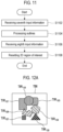
- FIG. 11 is a flowchart illustrating a process of resetting a 2D region of interest by performing outline processing in at least two 2D regions of interest set on the substrate image according to the first embodiment of the present disclosure.
- the processor 130 when input information (hereinafter, referred to as "seventh input information") for making a request for outline processing of at least two 2D regions of interest set on the substrate image is received through the user input part 120 in 51102, the processor 130 is configured to perform the outline processing upon the at least two 2D regions of interest set on the substrate image in accordance with the seventh input information in S1104.
- the outline processing corresponds to displaying only the outlines of the 2D regions of interest and making the inside of the 2D region of interest transparent.
- Various known methods may be used for the outline processing, and thus a detailed description thereof will be omitted.
- the processor 130 is configured to perform the outline processing upon seven 2D regions of interest TIR 121 to TIR 127 (see FIG. 12A ) set on a substrate image TBI in accordance with the seventh input information, and display the seven 2D regions of interest TIR 121 to TIR 127 on the display part 140 only with outlines (see FIG. 12B ).
- the processor 130 When input information (hereinafter, referred to as "eighth input information") for selecting at least one 2D region of interest from the at least two 2D regions of interest in which the outline processing has been performed is received through the user input part 120 in S1106, the processor 130 is configured to reset the at least one 2D region of interest selected from the at least two 2D regions of interest in which the outline processing has been performed as a new 2D region of interest in accordance with the eighth input information in S1108.
- the processor 130 is configured to reset a 2D region of interest TIR123 among the two 2D regions of interest TIR 121 to TIR 127 in which the outline processing has been performed as a new 2D region of interest in accordance with the eighth input information.
- FIG. 13 is a flowchart illustrating a process of setting a region of interest according to the second embodiment of the present disclosure.
- the substrate photographing part 110 is configured to generate a light for acquiring a substrate image, and radiate the light on a substrate S in S1302. Further, the substrate photographing part 110 is configured to acquire image data of the substrate S by receiving the light reflected from the substrate S in S1304.
- the processor 130 is configured to generate a substrate image based on the image data provided from the substrate photographing part 110 in S1306.
- the substrate image is a 3D substrate image.
- the 3D substrate image generated by the processor 130 is displayed on the display part 140 in S1308.
- the processor 130 When input information (hereinafter, referred to as "ninth input information") for setting a region of interest at a particular position of the 3D substrate image is received through the user input part 120 in S1310, the processor 130 is configured to three-dimensionally display the region of interest on the display part 140 in accordance with the ninth input information in S1312. That is, the processor 130 is configured to display a region of interest having a 3D shape (hereinafter, referred to as a 3D region of interest) on the display part 140 in accordance with the ninth input information.
- the ninth input information is input information corresponding to the region of interest of the 3D shape having a bottom and a height at a predetermined position of the 3D image.
- the processor 130 is configured to display a 3D region of interest HIR of a 3D shape ("hexahedral shape" in this example) on the display part 140 based on the ninth input information received through the user input part 120, as illustrated in FIG. 14 .
- HIR 3D region of interest
- FIG. 14 reference characters "HBI" refer to the 3D substrate image.
- the shape of the 3D region of interest is the hexahedral shape in the above-described example, the present disclosure is not necessarily limited thereto, and the 3D region of interest may have various shapes, such as a cylindrical shape, a conical shape, or the like. Further, although it has been described that one 3D region of interest is set on the 3D substrate image in the above-described example, the present disclosure is not necessarily limited thereto, and at least two 3D regions of interest may be set.
- the processor 130 is configured to measure the height of the inspection object IO of the substrate S or a particular part (for example, a solder or the like) of the inspection object, based on the 3D region of interest set on the 3D substrate image to generate a height measurement value, and display the generated height measurement value on the display part 140. Since the height of the particular part can be measured using various known methods, a detailed description thereof will be omitted in the present embodiment.
- the processor 130 is configured to compare the height measurement value and a predetermined reference value.
- the reference value is a reference value for determining whether the inspection object is good or not good.
- the processor 130 is configured to determine that the inspection object is not good.
- the substrate inspection system 100 further include a storage part (not shown) that stores a database of color values corresponding to height values of the inspection object, and the processor 130 is configured to search the storage part, match the color value corresponding to the height measurement value with the 3D region of interest, and display the 3D region of interest on the display part 140.
- a storage part (not shown) that stores a database of color values corresponding to height values of the inspection object
- the processor 130 is configured to search the storage part, match the color value corresponding to the height measurement value with the 3D region of interest, and display the 3D region of interest on the display part 140.
- FIG. 15 is a flowchart illustrating a process of setting a region of interest according to the third embodiment of the present disclosure.
- the substrate photographing part 110 is configured to generate light for acquiring a substrate image and radiate the light on a substrate S in S1502. Further, the substrate photographing part 110 is configured to receive the light reflected from the substrate S and acquire image data of the substrate S in S1504.
- the processor 130 is configured to generate a 3D substrate image based on the image data provided from the substrate photographing part 110 in S1506.
- the 3D substrate image generated by the processor 130 is displayed on the display part 140 in S1508.
- the processor 130 When input information (hereinafter, referred to as "tenth input information") for setting a region of interest at a particular position of the 3D substrate image is received through the user input part 130 in S1510, the processor 130 is configured to display a 3D region of interest in a 3D shape on the display part 140 in accordance with the tenth input information in S1512.
- the tenth input information is input information corresponding to a region of interest in a 3D shape having the bottom and the height at a particular position of the 3D substrate image.
- the processor 130 is configured to generate a 2D substrate image based on the 3D substrate image and the 3D region of interest in S1514.
- the 2D substrate image is an image (hereinafter, referred to as a "2D development image") that is two-dimensionally developed from the 3D substrate image.
- the processor 130 is configured to generate a 2D development image DIM by two-dimensionally developing a 3D substrate image HBI, as illustrated in FIG. 16 .
- the 2D development image DIM includes 2D images corresponding to the top surface and four lateral surfaces of the 3D substrate image HBI. That is, the 2D development image DIM does not include a 2D image corresponding to the bottom (that is, the surface which cannot be photographed by the substrate photographing part 110) of the 3D substrate image HBI.
- the 2D substrate image is an image of a 2D view (hereinafter, referred to as a "2D view image") corresponding to the surface at which the 3D region of interest is located on the 3D substrate image.
- the processor 130 is configured to detect a 3D position of the 3D region of interest in the 3D image based on geometrical position information of the 3D region of interest.
- the processor 130 is configured to set a plurality of 2D views based on the detected 3D position, and generate 2D view images TVI 171 , TVI 172 and TVI 173 corresponding to the plurality of set 2D views, respectively (see FIG. 17 ).
- FIG. 17 In FIG.
- the 2D view image TVI 171 is an image corresponding to a top view
- the 2D view image TVI 172 is an image corresponding to a left view
- the 2D view image TVI 173 is an image corresponding to a front view.
- the 2D view images may be changed depending on the position at which the 3D region of interest is set on the 3D substrate image.
- the 2D substrate image generated by the processor 130 is displayed on the display part 140 in S1516.
- the 3D substrate image and the 2D substrate image are displayed on the display part 140 in leftward and rightward directions.
- the 3D substrate image and the 2D substrate image are displayed on the display part 140 in upward and downward directions.
- the 3D substrate image and the 2D development image are displayed on one display part in the above-described examples, the present disclosure is not necessarily limited thereto, and the 3D substrate image may be displayed on a first display part, and the 2D development image may be displayed on a second display part.
- the processor 130 is configured to generate a 2D region of interest based on the 3D region of interest in S1518, and display the generated 2D region of interest on the 2D substrate image on the display part 140 in S1520. According to an embodiment, the processor 130 is configured to generate the 2D region of interest based on geometrical position information of the 3D region of interest set (displayed) on the 3D substrate image.
- the processor 130 is configured to generate a 2D region of interest TIR based on geometrical position information of a 3D region of interest HIR. Further, the processor 130 is configured to overlappingly display the 2D region of interest TIR at the corresponding position of a 2D development image DIM on the display part 140.
- the processor 130 is configured to generate 2D regions of interest TIR 1 , TIR 2 and TIR 3 based on geometrical position information of a 3D region of interest HIR. Further, the processor 130 is configured to overlappingly display the 2D regions of interest TIR 1 , TIR 2 and TIR 3 at the corresponding positions of 2D view images TVI 171 , TVI 172 and TVI 173 on the display 140.
- the processor 130 is configured to measure the height of the inspection object on the substrate S or a particular part (for example, a solder or the like) of the inspection object based on the 3D region of interest set on the 3D substrate image to generate a height measurement value. Further, the processor 130 is configured to display the height measurement value on the display part 140. Since the height of the particular part can be measured using various known methods, a detailed description thereof will be omitted in the present embodiment.
- the processor 130 selectively compares the height measurement value and a reference value in a preset range.
- the reference value is a reference value for determining whether the condition of the inspection object is good or not good.
- the processor 130 is configured to determine that the inspection object is not good.
- the substrate inspection system 100 further include a storage part (not shown) that stores a database of color values corresponding to height values of the inspection object, and the processor 130 is configured to search the storage part, match the color value corresponding to the height measurement value with the 3D region of interest, and display the 3D region of interest on the display part 140.
- a storage part (not shown) that stores a database of color values corresponding to height values of the inspection object
- the processor 130 is configured to search the storage part, match the color value corresponding to the height measurement value with the 3D region of interest, and display the 3D region of interest on the display part 140.
- FIG. 20 is a flowchart illustrating a process of setting a region of interest according to the fourth embodiment of the present disclosure.
- the substrate photographing part 110 is configured to generate a light for acquiring a substrate image, and radiate the light on a substrate S in S2002. Further, the substrate photographing part 110 is configured to receive the light reflected from the substrate S, and acquire image data of the substrate S in S2004.
- the processor 130 is configured to generate a 2D substrate image based on the image data provided from the substrate photographing part 110 in S2006.
- the 2D substrate image generated by the processor 130 is displayed on the display part 140 in S2008.
- the 2D substrate image corresponds to a 2D development image that is two-dimensionally developed from the 3D substrate image.
- the processor 130 is configured to generate the 3D substrate image based on the image data, and generate the 2D development image by two-dimensionally developing the 3D substrate image.
- the 2D substrate image is a 2D view image corresponding to each of a plurality of 2D views.
- the processor 130 is configured to generate a 2D view image corresponding to each of the plurality of 2D views (the top view, the front view, and the left view) based on the image data.
- the processor 130 When input information (hereinafter, referred to as “eleventh input information") for setting a region of interest at a plurality of particular positions of the 2D substrate image is received through the user input part 120 in S2010, the processor 130 is configured to display a 2D region of interest on the display part 140 in accordance with the eleventh input information in S2012. Since the eleventh input information in the present embodiment is the same as the first input information in the first embodiment, a detailed description thereof will be omitted.
- the processor 130 is configured to generate a 3D substrate image based on the image data acquired in S2004.
- the processor 130 is configured to generate the 3D substrate image by applying a bucket algorithm on grating pattern images reflected from the inspection object on which a grating pattern light is radiated.
- the 3D substrate image generated by the processor 130 is displayed on the display part 140 in S2016.
- the 3D substrate image and the 2D substrate image are displayed on the display part 140 in leftward and rightward directions.
- the 3D substrate image and the 2D substrate image are displayed on the display part 140 in upward and downward directions.
- the 3D substrate image and the 2D substrate image are displayed on one display part in the above-described examples, the present disclosure is not necessarily limited thereto, and the 3D substrate image may displayed on a first display part and the 2D substrate image may be displayed on a second display part.
- the processor 130 is configured to generate a 3D region of interest based on the 2D region of interest set on the 2D substrate image in S2018. Further, the processor 130 is configured to display the 3D region of interest on the 3D substrate image on the display part 140 in S2020. According to an embodiment, the processor 130 is configured to generate the 3D region of interest based on geometrical position information of the 2D region of interest set (displayed) on the 2D substrate image.
- the processor 130 may reset at least two regions of interest set on the 2D region of interest, as illustrated in FIGS. 5 to 12C according to the first embodiment.
- FIG. 21 is a block diagram schematically illustrating the configuration of a substrate inspection system according to a fifth embodiment of the present disclosure.
- a substrate inspection system 2100 includes a substrate photographing part 2110.
- the substrate photographing part 2110 is configured to radiate a light on a substrate having an inspection object, and receive the light reflected from the substrate so as to acquire image data corresponding to the inspection object in the substrate.
- the image data includes a plurality of view data.
- FIG. 22 is a diagram schematically illustrating the substrate photographing part 2110 according to the fifth embodiment of the present disclosure.
- the substrate photographing part 2110 includes projection portions 2210-1, 2210-2, 2210-3 and 2210-4.
- the projection portions 2210-1, 2210-2, 2210-3 and 2210-4 are configured to radiate a pattern light on the substrate S to measure the shape of an inspection object IO that is formed on the substrate S. Since the projection portions 2210-1, 2210-2, 2210-3 and 2210-4 in the present embodiment are similar to the projection portions 210-1 and 210-2 in the first embodiment, a detailed description thereof will be omitted.
- the substrate photographing part 2110 further includes imaging portions 2220-1 to 2220-5.
- the imaging portions 2220-1 to 2220-5 are configured to receive the light that is radiated by the projection portions 2210-1, 2210-2, 2210-3 and 2210-4 and reflected from the substrate S, and acquire image data corresponding to the substrate S. That is, the imaging portions 2220-1 to 2220-5 are configured to acquire image data corresponding to the substrate S by photographing the substrate S through the radiation of the pattern light by the projection portions2210-1 to 2210-4.
- the imaging portions 2220-1 to 2220-5 include a Charge-Coupled Device (CCD) camera or a Complementary Metal Oxide Semiconductor (CMOS) camera, but are not limited thereto.
- CCD Charge-Coupled Device
- CMOS Complementary Metal Oxide Semiconductor
- the imaging portion 2220-1 is installed at an upper position perpendicular to the substrate S, and the imaging portions 2220-2 to 2220-5 are separated from each other at a predetermined angle in a circumferential direction, and are installed below the imaging portion 2220-1.
- Each of the imaging portions 2220-1 to 2220-5 is configured to acquire image data (hereinafter, referred to as "view data") of a corresponding view. That is, the imaging portion 2220-1 is configured to acquire view data (hereinafter, referred to as "top view data") corresponding to a top view of the substrate S.
- the imaging portion 2220-2 is configured to acquire view data (hereinafter, referred to as "front view data”) corresponding to a front view of the substrate S.
- the imaging portion 2220-3 is configured to acquire view data (hereinafter, referred to as "rear view data”) corresponding to a rear view of the substrate S.
- the imaging portion 2220-4 is configured to acquire view data (hereinafter, referred to as "left view data”) corresponding to a left view of the substrate S.
- the imaging portion 2220-5 is configured to acquire view data (hereinafter, referred to as "right view data”) corresponding to a right view of the substrate S.
- the substrate inspection system 2100 includes five imaging portions 2220-1 to 2220-5 in the above-described example, the present disclosure is not necessarily limited thereto, and the number of imaging portions may vary as needed.
- the substrate photographing part 2110 further includes a stage 2230.
- the stage 2230 supports and fixes the substrate S. Since the stage 2230 in the present embodiment is the same as the stage 2230 in the first embodiment, a detailed description thereof will be omitted in the present embodiment.
- the substrate photographing part 2110 illustrated in FIG. 22 is one embodiment of substrate inspection devices which may acquire image data corresponding to the substrate S, but is not necessarily limited to the shape illustrated in FIG. 22 .
- the substrate inspection system 2100 further includes a user input part 2120.
- the user input part 2120 is configured to receive input information for setting a region of interest with respect to a substrate image corresponding to the substrate S from the user. Further, the user input part 2120 is configured to receive input information for adjusting reference data for a plurality of view data and setting an inspection condition for the region of interest.
- the substrate inspection system 2100 further includes a processor 2130.
- the processor 2130 is configured to generate a substrate image based on image data (that is, view data) provided from the substrate photographing part 2110.
- the substrate image includes a 3D image.
- the substrate image includes a 3D image corresponding to each of a plurality of view data.
- the substrate image may be an image corresponding to the entire substrate S, a part of the substrate S, or one inspection object IO.
- the processor 2130 is configured to display the region of interest for the substrate image on the display part 140 based on the input information provided from the user input part 2120.
- the processor 2130 is configured to determine whether the substrate S is good or not good by inspecting the region of interest set on the substrate image.
- the substrate inspection system 2100 further includes a display part 2140.
- the display part 2140 is configured to three-dimensionally display the substrate image generated by the processor 2130. Further, the display part 2140 is configured to three-dimensionally display the region of interest set on the substrate image.
- the display part 2140 includes a Liquid Crystal Display (LCD), a touch screen, and the like, but is not necessarily limited thereto.
- LCD Liquid Crystal Display
- FIG. 23 is a flowchart illustrating a process of performing substrate inspection according to an embodiment of the present disclosure.
- the substrate photographing part 2110 is configured to generate light for acquiring a substrate image, and radiate the light on the substrate S in S2302. Further, the substrate photographing part 2110 is configured to acquire image data of the substrate S by receiving the light reflected from the substrate S in S2304.
- the image data includes view data corresponding to each of the imaging portions 2220-1 to 2220-5.
- the processor 2130 is configured to generate a substrate image based on the image data provided from the substrate photographing part 2110 in S2306.
- the substrate image is a 3D substrate image.
- the 3D substrate image generated by the processor 2130 is displayed on the display part 2140 in S2308.
- the processor 2130 When input information (hereinafter, referred to as "twelfth input information") for setting a region of interest at a particular position of the 3D substrate image is received through the user input part 2120 in S2310, the processor 2130 is configured to display a 3D region of interest on the display part 2140 in accordance with the twelfth input information in S2312. Since the twelfth input information is the same as the ninth input information in the second embodiment, a detailed description thereof will be omitted in the present embodiment.
- the processor 2130 When input information (hereinafter, referred to as "thirteenth input information") for selecting one of a plurality of views is received through the user input part 2120 in S2314, the processor 2130 is configured to generate a view image based on view data corresponding to the thirteenth input information in S2316.
- the view image generated by the processor 2130 is displayed on the display part 2140 in S2318.
- the processor 2130 is configured to generate a top view image VI TOP corresponding to the top view based on the view data acquired by the imaging portion 2220-1, as illustrated in FIG. 24 .
- the processor 2130 is configured to generate a rear view image VI REAR corresponding to the rear view based on the view data acquired by the third imaging portion 2220-3, as illustrated in FIG. 25 .
- reference character B solder indicates a solder bridge.
- the processor 2130 is configured to generate view images (a front view image, a left view image, and a right view image) based on the view data acquired by the corresponding imaging portions in accordance with the thirteenth input information.
- the processor 2130 when input information (hereinafter, referred to as "fourteenth input information") for setting an inspection condition for determining whether the inspection object is good or not good in the view image is received through the user input part 2120 in S2320, the processor 2130 is configured to generate the inspection condition in accordance with the fourteenth input information in S2322. For example, the processor 2130 is configured to generate the inspection condition for determining whether the inspection object IO is good or not good based on the fourteenth input information.
- the processor 2130 may adjust the reference data in accordance with the fifteenth input information.
- the processor 2130 is configured to determine whether the inspection object IO is good or not good by inspecting the 3D region of interest in each of the plurality of view images based on the generated inspection condition in S2324. For example, the processor 2130 is configured to determine whether the inspection object IO is good or not good by inspecting the 3D region of interest in each of the top view image VI TOP , the rear view image VI REAR , the front view image, the left view image, and the right view image based on the inspection condition.
- the processor 2130 is configured to determine whether the substrate S is good or not good based on the determination of whether the inspection object IO is good or not good in each of the plurality of view images in S2326.
- the processor 2130 when it is determined that inspection object IO is good in a predetermined number of view images or more among the plurality of view images, the processor 2130 is configured to determine that the substrate S is good.
- the predetermined number may be three, but is not necessarily limited thereto.
- the processor 2130 when it is determined that the inspection object IO is good in the top view image, the front view image and the rear view image, the processor 2130 is configured to determine that the substrate S is good. In another example, when it is determined that the inspection object IO is good in the front view image and the left view image, the processor 2130 is configured to determine that the substrate S is not good (NG).
- the processor 2130 when it is determined that the inspection object IO is not good in a predetermined number of view images or more among the plurality of view images, the processor 2130 is configured to determine that the substrate S is not good.
- the predetermined number may be two, but is not necessarily limited thereto.
- the processor 2130 when it is determined that the inspection object IO is not good in the rear view image and the left view image, the processor 2130 is configured to determine that the substrate S is not good.
- the processor 2130 when it is determined that the inspection object IO is not good in one of the plurality of view images, the processor 2130 is configured to determine that the substrate S is not good. For example, when it is determined that the inspection object IO is not good by the solder bridge B solder in the rear view image, as illustrated in FIG. 25 , the processor S2130 is configured to determine that the substrate S is not good.
- the quality result of the substrate S determined by the processor 2130 may be displayed on the display part 2140 in various forms.
- the present disclosure is not necessarily limited thereto, and an inspection condition may be generated for each of the plurality of view images, in which case the 3D region of interest in each of the plurality of view images may be inspected based on each inspection condition.
- a substrate inspection method performed by the processor is described through particular embodiments, the method can additionally be implemented as computer-readable code on a computer-readable recording medium.
- the computer-readable recording medium includes all types of recording devices that store computer-system-readable data.
- the computer-readable recording medium includes a ROM, a RAM, a CD-ROM, a magnetic tape, a floppy disc, an optical data storage device, and the like, and also includes an implementation in the form of a carrier wave (for example, transmission over the Internet).
- the computer-readable recording medium may be distributed across computer systems connected over a network, and thus may store and execute computer-readable code in a distributed manner.
- a functional program, code, and code segments for implementing the embodiments may be easily inferred by programmers skilled in the art.
Landscapes
- Engineering & Computer Science (AREA)
- Physics & Mathematics (AREA)
- General Physics & Mathematics (AREA)
- Manufacturing & Machinery (AREA)
- Theoretical Computer Science (AREA)
- Microelectronics & Electronic Packaging (AREA)
- Computer Hardware Design (AREA)
- Computer Vision & Pattern Recognition (AREA)
- Power Engineering (AREA)
- Geometry (AREA)
- General Engineering & Computer Science (AREA)
- Quality & Reliability (AREA)
- Computer Graphics (AREA)
- Software Systems (AREA)
- Optics & Photonics (AREA)
- Investigating Materials By The Use Of Optical Means Adapted For Particular Applications (AREA)
- Image Processing (AREA)
- Length Measuring Devices By Optical Means (AREA)
- Image Analysis (AREA)
Description
- The present disclosure relates to the field of substrate inspection technology, and more particularly to a method and a system for inspecting a substrate capable of determining whether the substrate is good or not good by inspecting an application state of leads and a mounting state of electronic components on the surface of a printed circuit board (PCB) used as a circuit of an electronic device.
- In order to verify the reliability of a substrate on which electronic components are mounted, it is generally necessary to inspect whether the substrate is properly manufactured before and after the electronic components are mounted thereon. For example, it is necessary to inspect whether leads are properly applied on pad regions of the substrate before the electronic components are mounted on the substrate or whether the electronic components are properly mounted after the electronic components are mounted on the substrate.
- Recently, in order to precisely measure inspection objects (for example, electronic components or the like) mounted on the substrate, technology for measuring a 3D shape of an inspection object by using a substrate inspection apparatus, which includes at least one illumination part configured to radiate a pattern light on the inspection object and a camera configured to acquire image data by photographing an image of the inspection object through the irradiation of the pattern light, has been used.
- The substrate inspection apparatus generates an image of the substrate based on image data, sets a predetermined region of interest (ROI) on the image of the substrate, and inspects whether the inspection object is properly formed within the region of interest. In the prior art, the region of interest is fixed to a particular shape, for example, a rectangle. Accordingly, when a plurality of regions of interest is set on the image of the substrate, a new region of interest cannot be set by combining a region of interest with the previously set region of interest, and must be set by newly adding a region of interest. Meanwhile, as the shapes of electronic components mounted on the substrate become more diverse, it is necessary to set the region of interest having arbitrary shape on the image of the substrate, and it is also necessary to set a 3D region of interest on a 3D image of the substrate.
- In the prior art, it is determined whether the inspection object of the substrate is good or not good (non-defective or defective), based on an inspection condition for one view. Accordingly, in order to determine whether the substrate is good or not good, there is a case where image data even for the same inspection object are acquired several times and the inspection object is inspected. As a result, it takes a longer time to inspect the substrate.
-
US 2014/009601 A1 , considering several views, andUS 2011/002529 A1 , considering different captured images, disclose methods for substrate inspection according to the state of the art. - The aforementioned technical problem is solved by the method and apparatus of the annexed claims.
- The present disclosure provides a substrate inspection method and system for setting a region of interest having various shapes, such as an arbitrary 2D shape and/or 3D shape, as a region of interest on an image of the substrate in order to determine whether the substrate is good or not good by inspecting an application state of a lead on the substrate or a mounting state of electronic components on the substrate.
- Further, the present disclosure provides a substrate inspection method and system for determining whether an inspection object is good or not good by using view data (that is, a view image) corresponding to each of a plurality of views based on an inspection condition for each of the plurality of views and determining whether the substrate is good or not good according to the result of determining whether the inspection object is good or not good.
- In accordance with an aspect of the present disclosure, a method of inspecting a substrate is provided. The method includes: generating and displaying a 2D image of a substrate based on image data acquired from the substrate having an inspection object; receiving first input information including arbitrary point data or line data for setting a region of interest at a plurality of particular positions of the 2D image from a user; and displaying the region of interest corresponding to the point data or the line data as a 2D region of interest having an arbitrary shape in accordance with the first input information.
- In accordance with another aspect of the present disclosure, a system for inspecting a substrate is provided. The system includes: a processor configured to generate a 2D image of the substrate based on image data acquired from the substrate including an inspection object; a display part configured to display the 2D image; and a user input part configured to receive first input information including arbitrary point data or line data for setting a region of interest at a plurality of particular positions of the 2D image from a user, wherein the processor is further configured to display the region of interest corresponding to the point data or the line data as a 2D region of interest having an arbitrary shape in accordance with the first input information.
- In accordance with another aspect of the present disclosure, a method of inspecting a substrate is provided. The method includes: generating and displaying a 3D image of the substrate based on image data acquired from the substrate having an inspection object; receiving input information corresponding to a region of interest in a 3D shape having a bottom and a height at a predetermined position of the 3D image from a user; and displaying the region of interest as a 3D region of interest having a 3D shape in accordance with the input information.
- In accordance with another aspect of the present disclosure, a system for inspecting a substrate is provided. The system includes: a processor configured to generate a 3D image of the substrate based on image data acquired from the substrate having an inspection object; a display part configured to display the 3D image; and a user input part configured to receive input information corresponding to a region of interest in a 3D shape having a bottom and a height at a predetermined position of the 3D image, from a user, wherein the processor is further configured to display the region of interest as a 3D region of interest in a 3D shape in accordance with the input information.
- The present disclosure can set a region of interest in various shapes according to a shape of an inspection object since the region of interest can be set on a 2D image of the substrate in an arbitrary 2D shape.
- The present disclosure can increase user's convenience in setting the region of interest since two regions of interest set on the 2D image of the substrate can be reset as one 2D region of interest and a 2D region of interest can be divided as at least two 2D regions of interest.
- The present disclosure can provide a 3D image of the substrate along with a 2D image of the substrate, and set a 3D region of interest in a 3D shape on the 3D image based on a 2D region of interest set on the 2D image.
- The present disclosure can three-dimensionally inspect the inspection object of the substrate since a region of interest can be three-dimensionally set on the 3D image of the substrate.
- The present disclosure can provide a 2D image of the substrate along with a 3D image of the substrate and set a 2D region of interest in an arbitrary shape on the 2D image based on a 3D region of interest set on the 3D image.
- The present disclosure can not only reduce a substrate inspection time but also increase the accuracy of the substrate inspection since it is determined whether the inspection object is good or not good in a substrate image for each of a plurality of views based on inspection conditions for each of the plurality of views.
-
-
FIG. 1 is a block diagram schematically illustrating the configuration of a substrate inspection system according to a first embodiment of the present disclosure; -
FIG. 2 is a diagram schematically illustrating a substrate photographing part ofFIG. 1 ; -
FIG. 3 is a flowchart illustrating a process of setting a region of interest according to the first embodiment of the present disclosure; -
FIG. 4 illustrates an example of a region of interest according to the first embodiment of the present disclosure; -
FIG. 5 is a flowchart illustrating a process of resetting at least two 2D regions of interest (combination of the 2D regions of interest) set on a substrate image according to the first embodiment of the present disclosure; -
FIGS. 6A and6B are diagrams illustrating examples of resetting at least two 2D regions of interest (combination of the 2D regions of interest) set on a substrate image according to the first embodiment of the present disclosure; -
FIG. 7 is a flowchart illustrating a process of resetting at least two 2D regions of interest (removal of the 2D regions of interest) set on a substrate image according to the first embodiment of the present disclosure; -
FIG. 8 is a diagram illustrating an example of resetting at least two 2D regions of interest (removal of the 2D regions of interest) set on a substrate image according to the first embodiment of the present disclosure; -
FIG. 9 is a flowchart illustrating a process of resetting 2D regions of interest (division of the 2D region of interest) set on a substrate image according to the first embodiment of the present disclosure; -
FIG. 10 is a diagram illustrating an example of resetting 2D regions of interest (division of the 2D region of interest) set on a substrate image according to the first embodiment of the present disclosure; -
FIG. 11 is a flowchart illustrating a process of resetting a 2D region of interest by performing outline processing on at least two 2D regions of interest set on a substrate image according to the first embodiment of the present disclosure; -
FIGS. 12A to 12C are diagrams illustrating examples of resetting a 2D region of interest by performing outline processing on at least two 2D regions of interest set on a substrate image according to the first embodiment of the present disclosure; -
FIG. 13 is a flowchart illustrating a process of setting a region of interest according to a second embodiment of the present disclosure; -
FIG. 14 illustrates an example of a region of interest according to the second embodiment of the present disclosure; -
FIG. 15 is a flowchart illustrating a process of setting a region of interest according to a third embodiment of the present disclosure; -
FIG. 16 illustrates an example of a 3D substrate image and a 2D development image according to the third embodiment of the present disclosure; -
FIG. 17 illustrates an example of a 3D substrate image and a 2D view image according to the third embodiment of the present disclosure; -
FIG. 18 is a diagram illustrating an example of displaying a 3D region of interest and a 2D region of interest according to the third embodiment of the present disclosure; -
FIG. 19 is a diagram illustrating an example of displaying a 3D region of interest and a 2D region of interest according to the third embodiment of the present disclosure; -
FIG. 20 is a flowchart illustrating a process of setting a region of interest according to a fourth embodiment of the present disclosure; -
FIG. 21 is a block diagram schematically illustrating the configuration of a substrate inspection system according to a fifth embodiment of the present disclosure; -
FIG. 22 is a diagram schematically illustrating the configuration of a substrate photographing part ofFIG. 21 ; -
FIG. 23 is a flowchart illustrating a process of performing substrate inspection according to the fifth embodiment of the present disclosure; -
FIG. 24 illustrates an example of a top view image according to the fifth embodiment of the present disclosure; and -
FIG. 25 illustrates an example of a rear view image according to the fifth embodiment of the present disclosure. - Hereinafter, the present disclosure will be described with reference to the accompanying drawings. The invention, defined by the annexed claims, corresponds to the aspects of the fifth embodiment of the disclosure.
- However, if it is deemed that there is a possibility of making the essentials of the present disclosure unnecessarily unclear in the following description, a detailed description of a widely known function or configuration will be omitted.
-
FIG. 1 is a block diagram schematically illustrating a configuration of a substrate inspection system according to a first embodiment of the present disclosure. Referring toFIG. 1 , thesubstrate inspection system 100 according to the present embodiment includes asubstrate photographing part 110. - The
substrate photographing part 110 is configured to radiate a light to a substrate including an inspection object, and receive the light reflected from the substrate, so as to acquire image data corresponding to the inspection object on the substrate. The substrate includes a printed circuit board (PCB) on which conductive wires and pads are formed. However, it may not be limited thereto. -
FIG. 2 is a diagram schematically illustrating thesubstrate photographing part 110 according to an embodiment of the present disclosure. Referring toFIG. 2 , thesubstrate photographing part 110 includes projection portions 210-1 and 210-2. - The projection portions 210-1 and 210-2 are configured to radiate a pattern light to the substrate S in order to measure a shape of the inspection object formed on the substrate S. The inspection object IO includes a solder (not shown) formed on the pad and electronic components (not shown) mounted on the substrate S. However, it may be limited thereto.
- According to an embodiment, the projection portions 210-1 and 210-2 include a
light source 211 configured to generate a light, agrating device 212 configured to convert the light from thelight source 211 into a pattern light, agrating transfer device 213 configured to pitch-transfer thegrating device 212, and aprojection lens 214 configured to project the pattern light converted by thegrating device 212 on the inspection object IO. Here, for phase transition of the pattern light, thegrating device 212 may be transferred by a predetermined distance (for example, 2π/N (N is a natural number larger than or equal to 2) through thegrating transfer part 213 such as a PZT (piezo) actuator. Unlike this, a grating pattern light of which the phase is transitioned using an image of a liquid crystal display device may be radiated instead of using thegrating device 212 and thegrating transfer part 213. However, the present disclosure is not necessarily limited thereto, and can be implemented by other means as long as the grating pattern light, the phase of which is transitioned, can be radiated. - A projection portion may be installed or a plurality of projection portions 210-1 and 210-2 may be installed separately from each other at regular angles in a circumferential direction. The projection portions 210-1 and 210-2 are installed at an incline at a predetermined angle relative to the substrate S and are configured to radiate the pattern light on the substrate S from a plurality of directions.
- The
substrate photographing part 110 further includes animaging portion 220. Theimaging portion 220 is configured to acquire the image data corresponding to the substrate S by receiving the light, which is radiated from the projection portions 210-1 and 210-2 and reflected from the substrate S. That is, theimaging portion 220 is configured to acquire the image data corresponding to the substrate S by photographing the substrate S through the radiated pattern light of the projection portions 210-1 and 210-2. In one example, theimaging portion 220 may be installed on an upper position perpendicular to the substrate S. In another example, a plurality ofimaging portions 220 may be installed at an upper position perpendicular to the substrate S, and at positions, which are separated at a predetermined angle in a circumferential direction and are below the upper position. Theimaging portion 220 includes a charge-coupled device (CCD) camera or a complementary metal oxide semiconductor (CMOS) camera. However, it may not be limited thereto. - The
substrate photographing part 110 further includes astage 230. Thestage 230 is configured to support and fix the substrate S. According to an embodiment, thestage 230 includes afirst stage 231 configured to support and fix one end of the substrate S and asecond stage 232 configured to support and fix the other end of the substrate S. - The
substrate photographing part 110 illustrated inFIG. 2 is only one embodiment of a substrate inspection device that may acquire image data corresponding to the substrate S, and accordingly, it should be noted that thesubstrate photographing part 110 is not necessarily limited to the shape illustrated inFIG. 2 . - Referring back to
FIG. 1 , thesubstrate inspection system 100 further includes auser input part 120. Theuser input part 120 receives input information for setting a region of interest (ROI) on an image corresponding to the substrate S (hereinafter, referred to as a "substrate image") from the user. The input information and the region of interest will be described below in more detail. Theuser input part 120 includes a keyboard, a mouse, a touch screen, and the like. However, it may not be limited thereto, and may be any device capable of receiving the input information from the user. - The
substrate inspection system 100 further includes aprocessor 130. Theprocessor 130 is configured to generate a substrate image based on the image data provided from thesubstrate photographing part 110. According to an embodiment, the substrate image includes a 2D image or a 3D image. According to an embodiment, the substrate image may be an image corresponding to the entire substrate S, a part of the substrate S, or one inspection object IO. Further, theprocessor 130 is configured to display the region of interest for the substrate image on adisplay part 140 based on the input information provided from theuser input part 120. In addition, theprocessor 130 is configured to perform the measurement for the region of interest set on the substrate image. - The
processor 130 is electrically connected to thesubstrate photographing part 110, theuser input part 120, and thedisplay part 140, and controls the operation of each element of thesubstrate inspection system 100, that is, thesubstrate photographing part 110, theuser input part 120, and thedisplay part 140. - The
substrate inspection system 100 further includes thedisplay part 140. Thedisplay part 140 is configured to two-dimensionally or three-dimensionally display the substrate image generated by theprocessor 130. Further, thedisplay part 140 is configured to two-dimensionally or three-dimensionally display the region of interest set on the substrate image. Thedisplay part 140 may include a liquid crystal display (LCD), a touch screen, or the like. However, it may not be limited thereto. - Hereinafter, an embodiment for setting the region of interest on the substrate image will be described with reference to the accompanying drawings.
-
FIG. 3 is a flowchart illustrating a process of setting a region of interest according to the first embodiment of the present disclosure. Referring toFIG. 3 , thesubstrate photographing part 110 is configured to generate a light for acquiring a substrate image and radiate the light on the substrate S in S302. Further, thesubstrate photographing part 110 is configured to receive the light reflected from the substrate S and acquire image data of the substrate S in S304. - The
processor 130 is configured to generate a substrate image based on the image data provided from thesubstrate photographing part 110 in S306. The substrate image in the present embodiment corresponds to a 2D substrate image. The 2D substrate image generated by theprocessor 130 is displayed on thedisplay part 140 in S308. - When input information (hereinafter, referred to as "first input information") for setting the region of interest at a plurality of particular positions in the 2D substrate image is received through the
user input part 120 in S310, theprocessor 130 is configured to two-dimensionally display the region of interest in a predetermined shape in accordance with the first input information in S312. - According to an embodiment, the first input information includes predetermined point data. For example, when the first input information corresponding to arbitrary point data for setting the region of interest at a plurality of particular positions in the 2D substrate image is received, the
processor 130 is configured to generate the region of interest having an arbitrary 2D shape (hereinafter, referred to as a "2D region of interest") by connecting the point data with a line in accordance with the first input information. Further, theprocessor 130 is configured to display the 2D region of interest TIR4 on the display part 140 (seeFIG. 4 ). InFIG. 4 , the reference character "TBI" indicates the 2D substrate image. Here, as an example in which the 2D region of interest is generated by connecting the point data with the line, the 2D region of interest having an arbitrary shape (for example, a polygon, a circle, or the like) may be generated in a manner such that the points are sequentially connected in the order of dotting on the 2D substrate image and such that the last point is connected to the initial point. - According to another embodiment, the first input information includes line data. For example, when the first input information corresponding to arbitrary line data for setting the region of interest at a plurality of particular positions in the 2D substrate image is received, the
processor 130 is configured to generate the 2D region of interest by connecting line data in accordance with the first input information. Further, theprocessor 130 is configured to display the 2D region of interest on thedisplay 140 so that the 2D region of interest is displayed at the corresponding position of the 2D substrate image. Here, as an example of generating the 2D region of interest by connecting the line data, the 2D region of interest having an arbitrary shape, which includes lines, is generated on the 2D substrate image, but when the lines are not connected (partially open type), the 2D region of interest may be automatically completed by connecting open ends of the lines, which are connected, to each other. - Although it has been described that one 2D region of interest is displayed on the 2D substrate image in the above-described example, it may not be limited thereto, and a plurality of 2D regions of interest may be displayed on the 2D substrate image.
- As described above, according to the present embodiment, since the region of interest for the 2D substrate image may be set in an arbitrary 2D shape, the 2D inspection can be implemented by setting the region of interest according to the shape of the inspection object included in the substrate.
-
FIG. 5 is a flowchart illustrating a process of resetting at least two 2D regions of interest (combination of the 2D regions of interest) set on the substrate image according to the first embodiment of the present disclosure. Referring toFIG. 5 , when input information for selecting and dragging one of the at least two 2D regions of interest set on the substrate image (hereinafter, referred to as "second input information") is received through theuser input part 120 in S502, theprocessor 130 is configured to move the corresponding 2D region of interest in accordance with the second input information, and to display the 2D region of interest on thedisplay part 140 in S504. - Subsequently, when input information (hereinafter, referred to as "third input information") for resetting the at least two 2D regions of interest is received through the
user input part 120 in S506, theprocessor 130 is configured to detect a part where the at least two 2D regions of interest border each other in accordance with the third input information in S508. Since the part where the 2D regions of interest border each other can be detected through various known methods, this technology is not described in detail in the present embodiment. When the part where the at least two 2D regions of interest border each other is detected ("Yes" in S510), theprocessor 130 is configured to reset a 2D region of interest by combining the at least two 2D regions of interest based on the detected part in S512. - For example, as illustrated in
FIG. 6A , theprocessor 130 is configured to detect a part where a 2D region of interest TIR61 and a 2D region of interest TIR62 border each other. Further, theprocessor 130 is configured to reset a 2D region of interest TIR6 by combining the 2D region of interest TIR61 and the 2D region of interest TIR62 based on the detected part. That is, inFIG. 6A , the 2D regions of interest TIR61 and TIR62 border each other. - In another example, as illustrated in
FIG. 6B , theprocessor 130 is configured to detect a part where a 2D region of interest TIR63 and a 2D region of interest TIR64 border each other. Further, theprocessor 130 is configured to reset a 2D region of interest TIR6' by combining the 2D region of interest TIR63 and the 2D region of interest TIR64 based on the detected part. InFIG. 6 , the regions of interest TIR63 and TIR64 overlap with each other. - Meanwhile, when the part where the at least two 2D regions of interest border each other is not detected ("No" in S510), the steps S502 to S508 are performed again.
-
FIG. 7 is a flowchart illustrating a process of resetting at least two 2D regions of interest (combination of the 2D regions of interest) set on the substrate image as one 2D region of interest according to the first embodiment of the present disclosure. Referring toFIG. 7 , when input information (hereinafter, referred to as "fourth input information") for selecting and dragging one of at least two 2D regions of interest set on the substrate image is received through theuser input part 120 in S702, theprocessor 130 is configured to move the corresponding 2D region of interest in accordance with the fourth input information, and display the corresponding 2D region of interest on thedisplay part 140 in S704. - Subsequently, when input information (hereinafter, referred to as "fifth input information") for making a request for resetting the at least two 2D regions of interest is received through the
user input part 120 in S706, theprocessor 130 is configured to detect a region where the at least two 2D regions of interest overlap with each other in accordance with the fifth input information in S708. When the 2D region of interest corresponding to the fourth input information is a "first 2D region of interest" and the other 2D region of interest between the two 2D regions of interest is a "second 2D region of interest", the fifth information corresponds to input information for removing a region of the second 2D region of interest that overlaps with the first 2D region of interest. - When a region where the first 2D region of interest and the second 2D region of interest overlap with each other is detected ("Yes" in S710), the
processor 130 is configured to remove the region corresponding to the first 2D region of interest from the second 2D region of interest based on the detected region, and reset the first and second 2D regions of interest as one 2D region of interest in S712. - For example, as illustrated in
FIG. 8 , theprocessor 130 is configured to detect a region where a first 2D region of interest TIR81 and a second 2D region of interest TIR82 overlap with each other. Further, theprocessor 130 is configured to remove the region corresponding to the first 2D region of interest TIR81 from the second 2D region of interest TIR82 based on the detected region, so as to reset the first and second 2D regions of interest TIR81 and TIR82 as one 2D region of interest TIR8. - Meanwhile, when no region where the first 2D region of interest and the second 2D region of interest overlap with each other is detected ("No" in S710), the step S702 to the step S708 are performed again.
-
FIG. 9 is a flowchart illustrating a process of resetting a 2D region of interest (division of the 2D region of interest) set on the substrate image according to the first embodiment of the present disclosure, wherein the 2D region of interest is reset by dividing one 2D region of interest into at least two regions. - Referring to
FIG. 9 , when input information (hereinafter, referred to as "sixth input information") including arbitrary point data or line data at one or more particular positions in the 2D region of interest set on the substrate image is received through theuser input part 120 in S902, theprocessor 130 is configured to set at least one division line (hereinafter, referred to as a "region division line") for dividing the 2D region of interest in accordance with the sixth input information in S904. For example, as illustrated inFIG. 10 , theprocessor 130 is configured to set a region division line RVL on a 2D region of interest TIR10 set on the substrate image in accordance with the sixth input information. - The
processor 130 is configured to divide the 2D region of interest into at least two regions based on the set region division line in S906. Further, theprocessor 130 is configured to reset at least two 2D regions of interest based on the at least two regions in S908. For example, as illustrated inFIG. 10 , theprocessor 130 is configured to reset two 2D regions of interest TIR101 and TIR102 by dividing the 2D region of interest TIR10 into two regions based on the region division line RVL. Here, it should be noted that the division of the region may be uniform division or non-uniform division. - Although it has been described that one division line is set on the 2D region of interest and two 2D regions of interest are reset in the above-described example, the present disclosure is not necessarily limited thereto, and one or a plurality of region division lines may be set on the 2D region of interest, in which case two or more 2D regions of interest may be reset.
-
FIG. 11 is a flowchart illustrating a process of resetting a 2D region of interest by performing outline processing in at least two 2D regions of interest set on the substrate image according to the first embodiment of the present disclosure. - Referring to
FIG. 11 , when input information (hereinafter, referred to as "seventh input information") for making a request for outline processing of at least two 2D regions of interest set on the substrate image is received through theuser input part 120 in 51102, theprocessor 130 is configured to perform the outline processing upon the at least two 2D regions of interest set on the substrate image in accordance with the seventh input information in S1104. Here, the outline processing corresponds to displaying only the outlines of the 2D regions of interest and making the inside of the 2D region of interest transparent. Various known methods may be used for the outline processing, and thus a detailed description thereof will be omitted. - For example, the
processor 130 is configured to perform the outline processing upon seven 2D regions of interest TIR121 to TIR127 (seeFIG. 12A ) set on a substrate image TBI in accordance with the seventh input information, and display the seven 2D regions of interest TIR121 to TIR127 on thedisplay part 140 only with outlines (seeFIG. 12B ). - When input information (hereinafter, referred to as "eighth input information") for selecting at least one 2D region of interest from the at least two 2D regions of interest in which the outline processing has been performed is received through the
user input part 120 in S1106, theprocessor 130 is configured to reset the at least one 2D region of interest selected from the at least two 2D regions of interest in which the outline processing has been performed as a new 2D region of interest in accordance with the eighth input information in S1108. - For example, the
processor 130 is configured to reset a 2D region of interest TIR123 among the two 2D regions of interest TIR121 to TIR127 in which the outline processing has been performed as a new 2D region of interest in accordance with the eighth input information. - Although it has been described that only one 2D region of interest is selected and reset as a new 2D region of interest in the above-described example, the present disclosure is not necessarily limited thereto, and a plurality of 2D regions of interest may be selected and reset as a new 2D region of interest.
- Since elements of a substrate inspection system according to a second embodiment are the same as the elements of the
substrate inspection system 100 according to the first embodiment, a detailed description thereof will be omitted in the present embodiment. -
FIG. 13 is a flowchart illustrating a process of setting a region of interest according to the second embodiment of the present disclosure. Referring toFIG. 13 , thesubstrate photographing part 110 is configured to generate a light for acquiring a substrate image, and radiate the light on a substrate S in S1302. Further, thesubstrate photographing part 110 is configured to acquire image data of the substrate S by receiving the light reflected from the substrate S in S1304. - The
processor 130 is configured to generate a substrate image based on the image data provided from thesubstrate photographing part 110 in S1306. In the present embodiment, the substrate image is a 3D substrate image. The 3D substrate image generated by theprocessor 130 is displayed on thedisplay part 140 in S1308. - When input information (hereinafter, referred to as "ninth input information") for setting a region of interest at a particular position of the 3D substrate image is received through the
user input part 120 in S1310, theprocessor 130 is configured to three-dimensionally display the region of interest on thedisplay part 140 in accordance with the ninth input information in S1312. That is, theprocessor 130 is configured to display a region of interest having a 3D shape (hereinafter, referred to as a 3D region of interest) on thedisplay part 140 in accordance with the ninth input information. According to an embodiment, the ninth input information is input information corresponding to the region of interest of the 3D shape having a bottom and a height at a predetermined position of the 3D image. - For example, the
processor 130 is configured to display a 3D region of interest HIR of a 3D shape ("hexahedral shape" in this example) on thedisplay part 140 based on the ninth input information received through theuser input part 120, as illustrated inFIG. 14 . InFIG. 14 , reference characters "HBI" refer to the 3D substrate image. - Although it has been described that the shape of the 3D region of interest is the hexahedral shape in the above-described example, the present disclosure is not necessarily limited thereto, and the 3D region of interest may have various shapes, such as a cylindrical shape, a conical shape, or the like. Further, although it has been described that one 3D region of interest is set on the 3D substrate image in the above-described example, the present disclosure is not necessarily limited thereto, and at least two 3D regions of interest may be set.
- Selectively, the
processor 130 is configured to measure the height of the inspection object IO of the substrate S or a particular part (for example, a solder or the like) of the inspection object, based on the 3D region of interest set on the 3D substrate image to generate a height measurement value, and display the generated height measurement value on thedisplay part 140. Since the height of the particular part can be measured using various known methods, a detailed description thereof will be omitted in the present embodiment. - Further, selectively, the
processor 130 is configured to compare the height measurement value and a predetermined reference value. Here, the reference value is a reference value for determining whether the inspection object is good or not good. When it is determined that the height measurement value exceeds the reference value in the predetermined range based on a result of the comparison between the height measurement value and the reference value in the predetermined range, theprocessor 130 is configured to determine that the inspection object is not good. - Further, selectively, the
substrate inspection system 100 further include a storage part (not shown) that stores a database of color values corresponding to height values of the inspection object, and theprocessor 130 is configured to search the storage part, match the color value corresponding to the height measurement value with the 3D region of interest, and display the 3D region of interest on thedisplay part 140. - Since the elements of a substrate inspection system according to a third embodiment are the same as the elements of the
substrate inspection system 100 according to the first embodiment, a detailed description thereof will be omitted in the present embodiment. -
FIG. 15 is a flowchart illustrating a process of setting a region of interest according to the third embodiment of the present disclosure. Referring toFIG. 15 , thesubstrate photographing part 110 is configured to generate light for acquiring a substrate image and radiate the light on a substrate S in S1502. Further, thesubstrate photographing part 110 is configured to receive the light reflected from the substrate S and acquire image data of the substrate S in S1504. - The
processor 130 is configured to generate a 3D substrate image based on the image data provided from thesubstrate photographing part 110 in S1506. The 3D substrate image generated by theprocessor 130 is displayed on thedisplay part 140 in S1508. - When input information (hereinafter, referred to as "tenth input information") for setting a region of interest at a particular position of the 3D substrate image is received through the
user input part 130 in S1510, theprocessor 130 is configured to display a 3D region of interest in a 3D shape on thedisplay part 140 in accordance with the tenth input information in S1512. The tenth input information is input information corresponding to a region of interest in a 3D shape having the bottom and the height at a particular position of the 3D substrate image. - When the 3D region of interest is displayed (set) on the 3D substrate image, the
processor 130 is configured to generate a 2D substrate image based on the 3D substrate image and the 3D region of interest in S1514. - In an example, the 2D substrate image is an image (hereinafter, referred to as a "2D development image") that is two-dimensionally developed from the 3D substrate image. More specifically, the
processor 130 is configured to generate a 2D development image DIM by two-dimensionally developing a 3D substrate image HBI, as illustrated inFIG. 16 . At this time, the 2D development image DIM includes 2D images corresponding to the top surface and four lateral surfaces of the 3D substrate image HBI. That is, the 2D development image DIM does not include a 2D image corresponding to the bottom (that is, the surface which cannot be photographed by the substrate photographing part 110) of the 3D substrate image HBI. - In another example, the 2D substrate image is an image of a 2D view (hereinafter, referred to as a "2D view image") corresponding to the surface at which the 3D region of interest is located on the 3D substrate image. More specifically, the
processor 130 is configured to detect a 3D position of the 3D region of interest in the 3D image based on geometrical position information of the 3D region of interest. Theprocessor 130 is configured to set a plurality of 2D views based on the detected 3D position, and generate 2D view images TVI171, TVI172 and TVI173 corresponding to the plurality ofset 2D views, respectively (seeFIG. 17 ). InFIG. 17 , the 2D view image TVI171 is an image corresponding to a top view, the 2D view image TVI172 is an image corresponding to a left view, and the 2D view image TVI173 is an image corresponding to a front view. The 2D view images may be changed depending on the position at which the 3D region of interest is set on the 3D substrate image. - Referring back to
FIG. 15 , the 2D substrate image generated by theprocessor 130 is displayed on thedisplay part 140 in S1516. In an example, the 3D substrate image and the 2D substrate image are displayed on thedisplay part 140 in leftward and rightward directions. In another example, the 3D substrate image and the 2D substrate image are displayed on thedisplay part 140 in upward and downward directions. - Although it has been described that the 3D substrate image and the 2D development image are displayed on one display part in the above-described examples, the present disclosure is not necessarily limited thereto, and the 3D substrate image may be displayed on a first display part, and the 2D development image may be displayed on a second display part.
- The
processor 130 is configured to generate a 2D region of interest based on the 3D region of interest in S1518, and display the generated 2D region of interest on the 2D substrate image on thedisplay part 140 in S1520. According to an embodiment, theprocessor 130 is configured to generate the 2D region of interest based on geometrical position information of the 3D region of interest set (displayed) on the 3D substrate image. - In an example, as illustrated in
FIG. 18 , theprocessor 130 is configured to generate a 2D region of interest TIR based on geometrical position information of a 3D region of interest HIR. Further, theprocessor 130 is configured to overlappingly display the 2D region of interest TIR at the corresponding position of a 2D development image DIM on thedisplay part 140. - In another example, as illustrated in
FIG. 19 , theprocessor 130 is configured to generate 2D regions of interest TIR1, TIR2 and TIR3 based on geometrical position information of a 3D region of interest HIR. Further, theprocessor 130 is configured to overlappingly display the 2D regions of interest TIR1, TIR2 and TIR3 at the corresponding positions of 2D view images TVI171, TVI172 and TVI173 on thedisplay 140. - Selectively, the
processor 130 is configured to measure the height of the inspection object on the substrate S or a particular part (for example, a solder or the like) of the inspection object based on the 3D region of interest set on the 3D substrate image to generate a height measurement value. Further, theprocessor 130 is configured to display the height measurement value on thedisplay part 140. Since the height of the particular part can be measured using various known methods, a detailed description thereof will be omitted in the present embodiment. - Further, the
processor 130 selectively compares the height measurement value and a reference value in a preset range. Here, the reference value is a reference value for determining whether the condition of the inspection object is good or not good. When it is determined that the height measurement value exceeds the reference value in the predetermined range based on a result of the comparison between the height measurement value and the reference value in the predetermined range, theprocessor 130 is configured to determine that the inspection object is not good. - Further, selectively, the
substrate inspection system 100 further include a storage part (not shown) that stores a database of color values corresponding to height values of the inspection object, and theprocessor 130 is configured to search the storage part, match the color value corresponding to the height measurement value with the 3D region of interest, and display the 3D region of interest on thedisplay part 140. - Since elements of a substrate inspection system according to a fourth embodiment are the same as the elements of the
substrate inspection system 100 according to the first embodiment, a detailed description thereof will be omitted in the present embodiment. -
FIG. 20 is a flowchart illustrating a process of setting a region of interest according to the fourth embodiment of the present disclosure. Referring toFIG. 20 , thesubstrate photographing part 110 is configured to generate a light for acquiring a substrate image, and radiate the light on a substrate S in S2002. Further, thesubstrate photographing part 110 is configured to receive the light reflected from the substrate S, and acquire image data of the substrate S in S2004. - The
processor 130 is configured to generate a 2D substrate image based on the image data provided from thesubstrate photographing part 110 in S2006. The 2D substrate image generated by theprocessor 130 is displayed on thedisplay part 140 in S2008. - In an example, the 2D substrate image corresponds to a 2D development image that is two-dimensionally developed from the 3D substrate image. More specifically, the
processor 130 is configured to generate the 3D substrate image based on the image data, and generate the 2D development image by two-dimensionally developing the 3D substrate image. - In another example, the 2D substrate image is a 2D view image corresponding to each of a plurality of 2D views. Specifically, when input information for selecting a plurality of 2D views (for example, a top view, a front view, and a left view) for displaying the 2D region of interest is received from the user through the
user input part 120, theprocessor 130 is configured to generate a 2D view image corresponding to each of the plurality of 2D views (the top view, the front view, and the left view) based on the image data. - When input information (hereinafter, referred to as "eleventh input information") for setting a region of interest at a plurality of particular positions of the 2D substrate image is received through the
user input part 120 in S2010, theprocessor 130 is configured to display a 2D region of interest on thedisplay part 140 in accordance with the eleventh input information in S2012. Since the eleventh input information in the present embodiment is the same as the first input information in the first embodiment, a detailed description thereof will be omitted. - In S2014, the
processor 130 is configured to generate a 3D substrate image based on the image data acquired in S2004. For example, theprocessor 130 is configured to generate the 3D substrate image by applying a bucket algorithm on grating pattern images reflected from the inspection object on which a grating pattern light is radiated. The 3D substrate image generated by theprocessor 130 is displayed on thedisplay part 140 in S2016. In an example, the 3D substrate image and the 2D substrate image are displayed on thedisplay part 140 in leftward and rightward directions. In another example, the 3D substrate image and the 2D substrate image are displayed on thedisplay part 140 in upward and downward directions. - Although it has been described that the 3D substrate image and the 2D substrate image are displayed on one display part in the above-described examples, the present disclosure is not necessarily limited thereto, and the 3D substrate image may displayed on a first display part and the 2D substrate image may be displayed on a second display part.
- The
processor 130 is configured to generate a 3D region of interest based on the 2D region of interest set on the 2D substrate image in S2018. Further, theprocessor 130 is configured to display the 3D region of interest on the 3D substrate image on thedisplay part 140 in S2020. According to an embodiment, theprocessor 130 is configured to generate the 3D region of interest based on geometrical position information of the 2D region of interest set (displayed) on the 2D substrate image. - Selectively, the
processor 130 may reset at least two regions of interest set on the 2D region of interest, as illustrated inFIGS. 5 to 12C according to the first embodiment. -
FIG. 21 is a block diagram schematically illustrating the configuration of a substrate inspection system according to a fifth embodiment of the present disclosure. Referring toFIG. 21 , asubstrate inspection system 2100 includes asubstrate photographing part 2110. - The
substrate photographing part 2110 is configured to radiate a light on a substrate having an inspection object, and receive the light reflected from the substrate so as to acquire image data corresponding to the inspection object in the substrate. In the present embodiment, the image data includes a plurality of view data. -
FIG. 22 is a diagram schematically illustrating thesubstrate photographing part 2110 according to the fifth embodiment of the present disclosure. Referring toFIG. 22 , thesubstrate photographing part 2110 includes projection portions 2210-1, 2210-2, 2210-3 and 2210-4. The projection portions 2210-1, 2210-2, 2210-3 and 2210-4 are configured to radiate a pattern light on the substrate S to measure the shape of an inspection object IO that is formed on the substrate S. Since the projection portions 2210-1, 2210-2, 2210-3 and 2210-4 in the present embodiment are similar to the projection portions 210-1 and 210-2 in the first embodiment, a detailed description thereof will be omitted. - The
substrate photographing part 2110 further includes imaging portions 2220-1 to 2220-5. The imaging portions 2220-1 to 2220-5 are configured to receive the light that is radiated by the projection portions 2210-1, 2210-2, 2210-3 and 2210-4 and reflected from the substrate S, and acquire image data corresponding to the substrate S. That is, the imaging portions 2220-1 to 2220-5 are configured to acquire image data corresponding to the substrate S by photographing the substrate S through the radiation of the pattern light by the projection portions2210-1 to 2210-4. The imaging portions 2220-1 to 2220-5 include a Charge-Coupled Device (CCD) camera or a Complementary Metal Oxide Semiconductor (CMOS) camera, but are not limited thereto. - In the present embodiment, the imaging portion 2220-1 is installed at an upper position perpendicular to the substrate S, and the imaging portions 2220-2 to 2220-5 are separated from each other at a predetermined angle in a circumferential direction, and are installed below the imaging portion 2220-1.
- Each of the imaging portions 2220-1 to 2220-5 is configured to acquire image data (hereinafter, referred to as "view data") of a corresponding view. That is, the imaging portion 2220-1 is configured to acquire view data (hereinafter, referred to as "top view data") corresponding to a top view of the substrate S. The imaging portion 2220-2 is configured to acquire view data (hereinafter, referred to as "front view data") corresponding to a front view of the substrate S. The imaging portion 2220-3 is configured to acquire view data (hereinafter, referred to as "rear view data") corresponding to a rear view of the substrate S. The imaging portion 2220-4 is configured to acquire view data (hereinafter, referred to as "left view data") corresponding to a left view of the substrate S. The imaging portion 2220-5 is configured to acquire view data (hereinafter, referred to as "right view data") corresponding to a right view of the substrate S.
- Although it has been described that the
substrate inspection system 2100 includes five imaging portions 2220-1 to 2220-5 in the above-described example, the present disclosure is not necessarily limited thereto, and the number of imaging portions may vary as needed. - The
substrate photographing part 2110 further includes astage 2230. Thestage 2230 supports and fixes the substrate S. Since thestage 2230 in the present embodiment is the same as thestage 2230 in the first embodiment, a detailed description thereof will be omitted in the present embodiment. - The
substrate photographing part 2110 illustrated inFIG. 22 is one embodiment of substrate inspection devices which may acquire image data corresponding to the substrate S, but is not necessarily limited to the shape illustrated inFIG. 22 . - Referring back to
FIG. 21 , thesubstrate inspection system 2100 further includes auser input part 2120. Theuser input part 2120 is configured to receive input information for setting a region of interest with respect to a substrate image corresponding to the substrate S from the user. Further, theuser input part 2120 is configured to receive input information for adjusting reference data for a plurality of view data and setting an inspection condition for the region of interest. - The
substrate inspection system 2100 further includes aprocessor 2130. Theprocessor 2130 is configured to generate a substrate image based on image data (that is, view data) provided from thesubstrate photographing part 2110. According to an embodiment, the substrate image includes a 3D image. According to an embodiment, the substrate image includes a 3D image corresponding to each of a plurality of view data. According to an embodiment, the substrate image may be an image corresponding to the entire substrate S, a part of the substrate S, or one inspection object IO. Further, theprocessor 2130 is configured to display the region of interest for the substrate image on thedisplay part 140 based on the input information provided from theuser input part 2120. In addition, theprocessor 2130 is configured to determine whether the substrate S is good or not good by inspecting the region of interest set on the substrate image. - The
substrate inspection system 2100 further includes adisplay part 2140. Thedisplay part 2140 is configured to three-dimensionally display the substrate image generated by theprocessor 2130. Further, thedisplay part 2140 is configured to three-dimensionally display the region of interest set on the substrate image. Thedisplay part 2140 includes a Liquid Crystal Display (LCD), a touch screen, and the like, but is not necessarily limited thereto. -
FIG. 23 is a flowchart illustrating a process of performing substrate inspection according to an embodiment of the present disclosure. Referring toFIG. 23 , thesubstrate photographing part 2110 is configured to generate light for acquiring a substrate image, and radiate the light on the substrate S in S2302. Further, thesubstrate photographing part 2110 is configured to acquire image data of the substrate S by receiving the light reflected from the substrate S in S2304. In the present embodiment, the image data includes view data corresponding to each of the imaging portions 2220-1 to 2220-5. - The
processor 2130 is configured to generate a substrate image based on the image data provided from thesubstrate photographing part 2110 in S2306. In the present embodiment, the substrate image is a 3D substrate image. The 3D substrate image generated by theprocessor 2130 is displayed on thedisplay part 2140 in S2308. - When input information (hereinafter, referred to as "twelfth input information") for setting a region of interest at a particular position of the 3D substrate image is received through the
user input part 2120 in S2310, theprocessor 2130 is configured to display a 3D region of interest on thedisplay part 2140 in accordance with the twelfth input information in S2312. Since the twelfth input information is the same as the ninth input information in the second embodiment, a detailed description thereof will be omitted in the present embodiment. - When input information (hereinafter, referred to as "thirteenth input information") for selecting one of a plurality of views is received through the
user input part 2120 in S2314, theprocessor 2130 is configured to generate a view image based on view data corresponding to the thirteenth input information in S2316. The view image generated by theprocessor 2130 is displayed on thedisplay part 2140 in S2318. For example, when the thirteenth input information for selecting a top view is received through theuser input part 2120, theprocessor 2130 is configured to generate a top view image VITOP corresponding to the top view based on the view data acquired by the imaging portion 2220-1, as illustrated inFIG. 24 . - Further, when the thirteenth input information for selecting a rear view is received through the
user input part 2120, theprocessor 2130 is configured to generate a rear view image VIREAR corresponding to the rear view based on the view data acquired by the third imaging portion 2220-3, as illustrated inFIG. 25 . InFIG. 25 , reference character Bsolder indicates a solder bridge. - Also, with respect to a front view, a left view, and a right view, the
processor 2130 is configured to generate view images (a front view image, a left view image, and a right view image) based on the view data acquired by the corresponding imaging portions in accordance with the thirteenth input information. - Referring back to
FIG. 23 , when input information (hereinafter, referred to as "fourteenth input information") for setting an inspection condition for determining whether the inspection object is good or not good in the view image is received through theuser input part 2120 in S2320, theprocessor 2130 is configured to generate the inspection condition in accordance with the fourteenth input information in S2322. For example, theprocessor 2130 is configured to generate the inspection condition for determining whether the inspection object IO is good or not good based on the fourteenth input information. - Selectively, when input information (hereinafter, referred to as "fifteenth input information") for adjusting reference data (for example, CAD data) of the substrate S with respect to each of a plurality of views is received through the
user input part 2120, theprocessor 2130 may adjust the reference data in accordance with the fifteenth input information. - The
processor 2130 is configured to determine whether the inspection object IO is good or not good by inspecting the 3D region of interest in each of the plurality of view images based on the generated inspection condition in S2324. For example, theprocessor 2130 is configured to determine whether the inspection object IO is good or not good by inspecting the 3D region of interest in each of the top view image VITOP, the rear view image VIREAR, the front view image, the left view image, and the right view image based on the inspection condition. - The
processor 2130 is configured to determine whether the substrate S is good or not good based on the determination of whether the inspection object IO is good or not good in each of the plurality of view images in S2326. - According to an embodiment, when it is determined that inspection object IO is good in a predetermined number of view images or more among the plurality of view images, the
processor 2130 is configured to determine that the substrate S is good. Here, the predetermined number may be three, but is not necessarily limited thereto. For example, when it is determined that the inspection object IO is good in the top view image, the front view image and the rear view image, theprocessor 2130 is configured to determine that the substrate S is good. In another example, when it is determined that the inspection object IO is good in the front view image and the left view image, theprocessor 2130 is configured to determine that the substrate S is not good (NG). - According to another embodiment, when it is determined that the inspection object IO is not good in a predetermined number of view images or more among the plurality of view images, the
processor 2130 is configured to determine that the substrate S is not good. Here, the predetermined number may be two, but is not necessarily limited thereto. For example, when it is determined that the inspection object IO is not good in the rear view image and the left view image, theprocessor 2130 is configured to determine that the substrate S is not good. - According to another embodiment, when it is determined that the inspection object IO is not good in one of the plurality of view images, the
processor 2130 is configured to determine that the substrate S is not good. For example, when it is determined that the inspection object IO is not good by the solder bridge Bsolder in the rear view image, as illustrated inFIG. 25 , the processor S2130 is configured to determine that the substrate S is not good. - Selectively, the quality result of the substrate S determined by the
processor 2130 may be displayed on thedisplay part 2140 in various forms. - Although it has been described that one inspection condition is generated and the 3D region of interest is inspected in each of the plurality of view images based on the generated inspection condition in the above-described embodiment, the present disclosure is not necessarily limited thereto, and an inspection condition may be generated for each of the plurality of view images, in which case the 3D region of interest in each of the plurality of view images may be inspected based on each inspection condition. Although a substrate inspection method performed by the processor is described through particular embodiments, the method can additionally be implemented as computer-readable code on a computer-readable recording medium. The computer-readable recording medium includes all types of recording devices that store computer-system-readable data. For example, the computer-readable recording medium includes a ROM, a RAM, a CD-ROM, a magnetic tape, a floppy disc, an optical data storage device, and the like, and also includes an implementation in the form of a carrier wave (for example, transmission over the Internet). Further, the computer-readable recording medium may be distributed across computer systems connected over a network, and thus may store and execute computer-readable code in a distributed manner. In addition, a functional program, code, and code segments for implementing the embodiments may be easily inferred by programmers skilled in the art.
Claims (8)
- A method of inspecting a substrate, characterized by comprising:generating (S2306), by a processor (2130) of a substrate inspection system (2100), a 3D image of the substrate based on image data acquired from the substrate having an inspection object, the image data comprising a plurality of view data;displaying (S2308), by the processor (2130), the 3D image of the substrate on a display part (2140) of the substrate inspection system (2100);receiving (S2310), by a user input part (2120) of the substrate inspection system (2100), input information for setting a 3D region of interest having a bottom and a height at a predetermined position of the 3D image from a user;displaying (S2312), by the processor (2130), the 3D region of interest on the 3D image on the display part (2140) in accordance with the input information, andcharacterized by further comprising: inspecting (S2324), by the processor (2130), the 3D region of interest in each of the plurality of view data, based on an inspection condition for determining whether the inspection object is good or not good in each of the plurality of view data; anddetermining (S2326), by the processor (2130), whether the substrate is good or not good based on the determination of whether the inspection object is good or not good in each of the plurality of view data,wherein the plurality of view data are acquired from a plurality of imaging portions (2220-1 to 2220-5) installed at different positions, respectively.
- The method of claim 1, wherein determining whether the substrate is good or not good comprises, when it is determined that the inspection object is good in a predetermined number of view data or more among the plurality of view data, determining that the substrate is good.
- The method of claim 1, wherein determining whether the substrate is good or not good comprises, when it is determined that the inspection object is not good in a predetermined number of view data or more among the plurality of view data, determining that the substrate is not good.
- The method of claim 1, wherein determining whether the substrate is good or not good comprises, when it is determined that the inspection object is not good in one of the plurality of view data, determining that the substrate is not good.
- A system (2100) for inspecting a substrate, characterized by comprising:a processor (2130) configured to generate a 3D image of the substrate based on image data acquired from the substrate having an inspection object;a display part (2140) configured to display the 3D image;a plurality of imaging portions (2220-1 to 2220-5) configured to acquire the image data including a plurality of view data, and installed at different positions, respectively; anda user input part (2120) configured to receive input information for setting a 3D region of interest having a bottom and a height at a predetermined position of the 3D image, from a user,wherein the processor (2130) is further configured to:display the 3D region of interest on the 3D image on the display part (2140) in accordance with the input information, andcharacterized in that the processor (2130) is further configured to inspect the 3D region of interest in each of the plurality of view data, based on an inspection condition for determining whether the inspection object is good or not good in each of the plurality of view data; anddetermine whether the substrate is good or not good based on the determination of whether the inspection object is good or not good in each of the plurality of view data.
- The system (2100) of claim 5, wherein the processor (2130) is configured to determine that the substrate is good when it is determined that the inspection object is good in a predetermined number of view data or more among the plurality of view data.
- The system (2100) of claim 5, wherein the processor (2130) is configured to determine that the substrate is not good when it is determined that the inspection object is not good in a predetermined number of view data or more among the plurality of view data.
- The system (2100) of claim 5, wherein the processor (2130) is configured to determine that the substrate is not good when it is determined that the inspection object is not good in one of the plurality of view data.
Applications Claiming Priority (4)
| Application Number | Priority Date | Filing Date | Title |
|---|---|---|---|
| KR20150028627 | 2015-02-27 | ||
| KR1020160008813A KR101784276B1 (en) | 2015-02-27 | 2016-01-25 | Board inspection method and system |
| EP16755780.0A EP3264448B1 (en) | 2015-02-27 | 2016-01-29 | Substrate inspection method and system |
| PCT/KR2016/000997 WO2016137130A1 (en) | 2015-02-27 | 2016-01-29 | Substrate inspection method and system |
Related Parent Applications (2)
| Application Number | Title | Priority Date | Filing Date |
|---|---|---|---|
| EP16755780.0A Division EP3264448B1 (en) | 2015-02-27 | 2016-01-29 | Substrate inspection method and system |
| EP16755780.0A Division-Into EP3264448B1 (en) | 2015-02-27 | 2016-01-29 | Substrate inspection method and system |
Publications (3)
| Publication Number | Publication Date |
|---|---|
| EP3764320A1 EP3764320A1 (en) | 2021-01-13 |
| EP3764320C0 EP3764320C0 (en) | 2023-07-19 |
| EP3764320B1 true EP3764320B1 (en) | 2023-07-19 |
Family
ID=56946136
Family Applications (2)
| Application Number | Title | Priority Date | Filing Date |
|---|---|---|---|
| EP20190465.3A Active EP3764320B1 (en) | 2015-02-27 | 2016-01-29 | Substrate inspection method and system |
| EP16755780.0A Active EP3264448B1 (en) | 2015-02-27 | 2016-01-29 | Substrate inspection method and system |
Family Applications After (1)
| Application Number | Title | Priority Date | Filing Date |
|---|---|---|---|
| EP16755780.0A Active EP3264448B1 (en) | 2015-02-27 | 2016-01-29 | Substrate inspection method and system |
Country Status (4)
| Country | Link |
|---|---|
| US (1) | US10672116B2 (en) |
| EP (2) | EP3764320B1 (en) |
| KR (2) | KR101784276B1 (en) |
| CN (1) | CN107408518B (en) |
Families Citing this family (7)
| Publication number | Priority date | Publication date | Assignee | Title |
|---|---|---|---|---|
| KR101784276B1 (en) * | 2015-02-27 | 2017-10-12 | 주식회사 고영테크놀러지 | Board inspection method and system |
| SG11201709029QA (en) * | 2017-05-02 | 2018-12-28 | Generic Power Pte Ltd | System and Method for Lead Foot Angle Inspection Using Multiview Stereo Vision |
| JP6897398B2 (en) * | 2017-07-31 | 2021-06-30 | セイコーエプソン株式会社 | 3D shape measuring device, robot system, and 3D shape measuring method |
| EP3640629B1 (en) | 2018-10-15 | 2024-05-08 | Koh Young Technology Inc | Focus-less inspection apparatus and method |
| KR102211600B1 (en) * | 2018-10-15 | 2021-02-03 | 주식회사 고영테크놀러지 | Apparatus for focus-less inspection and method thereof |
| CN109752392B (en) * | 2018-12-24 | 2021-08-03 | 苏州江奥光电科技有限公司 | PCB defect type detection system and method |
| IT202100001718A1 (en) | 2021-01-28 | 2022-07-28 | Getcoo S R L | METHOD OF PROCESSING AN IMAGE OF AN OBJECT AND SYSTEM FOR INSPECTING THE OBJECT. |
Citations (1)
| Publication number | Priority date | Publication date | Assignee | Title |
|---|---|---|---|---|
| US9885669B2 (en) * | 2010-12-29 | 2018-02-06 | Koh Young Technology Inc. | Method of inspecting a substrate |
Family Cites Families (25)
| Publication number | Priority date | Publication date | Assignee | Title |
|---|---|---|---|---|
| JPS6361104A (en) * | 1986-08-30 | 1988-03-17 | T Ii D:Kk | Apparatus for inspecting positional shift |
| JPH05102275A (en) | 1991-10-07 | 1993-04-23 | Sony Corp | Defect detection method and device |
| JPH06149967A (en) | 1992-11-16 | 1994-05-31 | Toshiba Medical Eng Co Ltd | Three-dimensional image diagnostic device |
| JPH1047929A (en) | 1996-07-31 | 1998-02-20 | Seidensha Denshi Kogyo Kk | Method and device for inspecting internal surface of cylinder |
| US5966677A (en) | 1997-02-28 | 1999-10-12 | Fiekowsky; Peter J. | High accuracy particle dimension measurement system |
| US6476913B1 (en) * | 1998-11-30 | 2002-11-05 | Hitachi, Ltd. | Inspection method, apparatus and system for circuit pattern |
| CN100428277C (en) * | 1999-11-29 | 2008-10-22 | 奥林巴斯光学工业株式会社 | Defect inspecting system |
| US7135676B2 (en) * | 2000-06-27 | 2006-11-14 | Ebara Corporation | Inspection system by charged particle beam and method of manufacturing devices using the system |
| DE102007047933B3 (en) | 2007-12-20 | 2009-02-26 | Vistec Semiconductor Systems Gmbh | Semiconductor wafer surface e.g. front side or rear side, inspecting method for detecting defects on wafer surface, involves processing parameter or type of image receiving for area fixed on surface with detection sensitivity of area |
| KR101056995B1 (en) | 2009-07-03 | 2011-08-16 | 주식회사 고영테크놀러지 | 3D shape inspection method |
| DE102010030859B4 (en) | 2009-07-03 | 2019-01-24 | Koh Young Technology Inc. | A method of inspecting a target mounted on a substrate |
| KR101133641B1 (en) | 2010-01-29 | 2012-04-10 | 주식회사 고영테크놀러지 | Method of inspecting three-dimensional shape |
| JP5357725B2 (en) | 2009-12-03 | 2013-12-04 | 株式会社日立ハイテクノロジーズ | Defect inspection method and defect inspection apparatus |
| US9390490B2 (en) * | 2010-01-05 | 2016-07-12 | Hitachi High-Technologies Corporation | Method and device for testing defect using SEM |
| KR101078781B1 (en) | 2010-02-01 | 2011-11-01 | 주식회사 고영테크놀러지 | Method of inspecting a three dimensional shape |
| JP5444092B2 (en) | 2010-04-06 | 2014-03-19 | 株式会社日立ハイテクノロジーズ | Inspection method and apparatus |
| JP5599062B2 (en) * | 2010-12-06 | 2014-10-01 | 株式会社リガク | X-ray diffraction apparatus and X-ray diffraction measurement method |
| JP5765651B2 (en) | 2011-02-01 | 2015-08-19 | Jukiオートメーションシステムズ株式会社 | 3D measuring device |
| JP5626122B2 (en) | 2011-05-30 | 2014-11-19 | 東京エレクトロン株式会社 | Substrate inspection apparatus, substrate inspection method, and storage medium |
| KR20150017421A (en) | 2013-07-17 | 2015-02-17 | 주식회사 고영테크놀러지 | Graphic user interface for three dimensional cuircuit board inspection apparatus |
| KR101457040B1 (en) | 2013-09-03 | 2014-10-31 | 주식회사 고영테크놀러지 | Graphic user interface for 3 dimensional cuircuit board inspection apparatus |
| US9494468B2 (en) * | 2013-10-01 | 2016-11-15 | Infineon Technologies Ag | Method of examining a substrate and corresponding device |
| CN103698910B (en) | 2013-11-28 | 2016-03-16 | 南京中电熊猫液晶显示科技有限公司 | A kind of foreign body checking machine and inspection method thereof |
| KR101784276B1 (en) * | 2015-02-27 | 2017-10-12 | 주식회사 고영테크놀러지 | Board inspection method and system |
| JP7188870B2 (en) * | 2017-05-31 | 2022-12-13 | 株式会社キーエンス | Image inspection equipment |
-
2016
- 2016-01-25 KR KR1020160008813A patent/KR101784276B1/en active IP Right Grant
- 2016-01-29 EP EP20190465.3A patent/EP3764320B1/en active Active
- 2016-01-29 EP EP16755780.0A patent/EP3264448B1/en active Active
- 2016-01-29 US US15/554,041 patent/US10672116B2/en active Active
- 2016-01-29 CN CN201680012305.1A patent/CN107408518B/en active Active
-
2017
- 2017-02-13 KR KR1020170019505A patent/KR101810992B1/en active IP Right Grant
Patent Citations (1)
| Publication number | Priority date | Publication date | Assignee | Title |
|---|---|---|---|---|
| US9885669B2 (en) * | 2010-12-29 | 2018-02-06 | Koh Young Technology Inc. | Method of inspecting a substrate |
Also Published As
| Publication number | Publication date |
|---|---|
| EP3264448A1 (en) | 2018-01-03 |
| EP3764320C0 (en) | 2023-07-19 |
| EP3264448A4 (en) | 2018-10-31 |
| KR101784276B1 (en) | 2017-10-12 |
| US10672116B2 (en) | 2020-06-02 |
| CN107408518B (en) | 2021-01-05 |
| KR20170019403A (en) | 2017-02-21 |
| US20180040118A1 (en) | 2018-02-08 |
| KR20160105295A (en) | 2016-09-06 |
| KR101810992B1 (en) | 2017-12-20 |
| CN107408518A (en) | 2017-11-28 |
| EP3764320A1 (en) | 2021-01-13 |
| EP3264448B1 (en) | 2020-09-23 |
Similar Documents
| Publication | Publication Date | Title |
|---|---|---|
| EP3764320B1 (en) | Substrate inspection method and system | |
| JP6211197B2 (en) | Board inspection equipment | |
| CN108616726A (en) | Exposal control method based on structure light and exposure-control device | |
| JP6104662B2 (en) | Measuring device, method and program | |
| JP2007286000A (en) | Inspecting device, inspecting method, and inspecting processing program | |
| US10986761B2 (en) | Board inspecting apparatus and board inspecting method using the same | |
| US10330609B2 (en) | Method and apparatus of inspecting a substrate with a component mounted thereon | |
| EP3525566B1 (en) | Substrate inspection device and substrate distortion compensating method using same | |
| JP2011149736A (en) | Appearance inspection apparatus and appearance inspection method | |
| KR101511089B1 (en) | Teaching data auto-generating method for aoi apparatus | |
| JP6792369B2 (en) | Circuit board inspection method and inspection equipment | |
| JP6229134B2 (en) | Measuring device | |
| JP2006031595A (en) | Image processing system | |
| US10360719B2 (en) | Method and apparatus for obtaining high-quality textures | |
| JP4389568B2 (en) | Defect inspection equipment | |
| EP3244198A1 (en) | Method and apparatus for inspecting a solder paste deposit with a digital mirror device | |
| JP7156794B2 (en) | Inspection device height information acquisition method and inspection device | |
| WO2016137130A1 (en) | Substrate inspection method and system | |
| EP4269940A2 (en) | Device and method for inspection | |
| JP2023030314A (en) | Three-dimensional measuring device and method for determining measurement error of height measurement in three-dimensional measurement | |
| JP2022147530A (en) | Feature position estimation method, feature position estimation device and feature position estimation program | |
| JPH08313226A (en) | Method of inspecting transparent object | |
| JP2001242093A (en) | Image density unevenness detecting method | |
| JP2005195443A (en) | Image measurement apparatus |
Legal Events
| Date | Code | Title | Description |
|---|---|---|---|
| PUAI | Public reference made under article 153(3) epc to a published international application that has entered the european phase |
Free format text: ORIGINAL CODE: 0009012 |
|
| STAA | Information on the status of an ep patent application or granted ep patent |
Free format text: STATUS: REQUEST FOR EXAMINATION WAS MADE |
|
| 17P | Request for examination filed |
Effective date: 20200904 |
|
| AC | Divisional application: reference to earlier application |
Ref document number: 3264448 Country of ref document: EP Kind code of ref document: P |
|
| AK | Designated contracting states |
Kind code of ref document: A1 Designated state(s): AL AT BE BG CH CY CZ DE DK EE ES FI FR GB GR HR HU IE IS IT LI LT LU LV MC MK MT NL NO PL PT RO RS SE SI SK SM TR |
|
| RBV | Designated contracting states (corrected) |
Designated state(s): AL AT BE BG CH CY CZ DE DK EE ES FI FR GB GR HR HU IE IS IT LI LT LU LV MC MK MT NL NO PL PT RO RS SE SI SK SM TR |
|
| RIC1 | Information provided on ipc code assigned before grant |
Ipc: G01N 21/956 20060101ALN20230321BHEP Ipc: G06T 7/62 20170101ALI20230321BHEP Ipc: G06T 7/00 20170101AFI20230321BHEP |
|
| GRAP | Despatch of communication of intention to grant a patent |
Free format text: ORIGINAL CODE: EPIDOSNIGR1 |
|
| STAA | Information on the status of an ep patent application or granted ep patent |
Free format text: STATUS: GRANT OF PATENT IS INTENDED |
|
| INTG | Intention to grant announced |
Effective date: 20230502 |
|
| RAP3 | Party data changed (applicant data changed or rights of an application transferred) |
Owner name: KOH YOUNG TECHNOLOGY INC. |
|
| GRAS | Grant fee paid |
Free format text: ORIGINAL CODE: EPIDOSNIGR3 |
|
| GRAA | (expected) grant |
Free format text: ORIGINAL CODE: 0009210 |
|
| STAA | Information on the status of an ep patent application or granted ep patent |
Free format text: STATUS: THE PATENT HAS BEEN GRANTED |
|
| AC | Divisional application: reference to earlier application |
Ref document number: 3264448 Country of ref document: EP Kind code of ref document: P |
|
| AK | Designated contracting states |
Kind code of ref document: B1 Designated state(s): AL AT BE BG CH CY CZ DE DK EE ES FI FR GB GR HR HU IE IS IT LI LT LU LV MC MK MT NL NO PL PT RO RS SE SI SK SM TR |
|
| REG | Reference to a national code |
Ref country code: GB Ref legal event code: FG4D |
|
| REG | Reference to a national code |
Ref country code: CH Ref legal event code: EP |
|
| REG | Reference to a national code |
Ref country code: DE Ref legal event code: R096 Ref document number: 602016081271 Country of ref document: DE |
|
| REG | Reference to a national code |
Ref country code: IE Ref legal event code: FG4D |
|
| U01 | Request for unitary effect filed |
Effective date: 20230720 |
|
| U07 | Unitary effect registered |
Designated state(s): AT BE BG DE DK EE FI FR IT LT LU LV MT NL PT SE SI Effective date: 20230727 |
|
| REG | Reference to a national code |
Ref country code: LT Ref legal event code: MG9D |
|
| PG25 | Lapsed in a contracting state [announced via postgrant information from national office to epo] |
Ref country code: GR Free format text: LAPSE BECAUSE OF FAILURE TO SUBMIT A TRANSLATION OF THE DESCRIPTION OR TO PAY THE FEE WITHIN THE PRESCRIBED TIME-LIMIT Effective date: 20231020 |
|
| PG25 | Lapsed in a contracting state [announced via postgrant information from national office to epo] |
Ref country code: IS Free format text: LAPSE BECAUSE OF FAILURE TO SUBMIT A TRANSLATION OF THE DESCRIPTION OR TO PAY THE FEE WITHIN THE PRESCRIBED TIME-LIMIT Effective date: 20231119 |
|
| U20 | Renewal fee paid [unitary effect] |
Year of fee payment: 9 Effective date: 20231219 |
|
| PG25 | Lapsed in a contracting state [announced via postgrant information from national office to epo] |
Ref country code: RS Free format text: LAPSE BECAUSE OF FAILURE TO SUBMIT A TRANSLATION OF THE DESCRIPTION OR TO PAY THE FEE WITHIN THE PRESCRIBED TIME-LIMIT Effective date: 20230719 Ref country code: NO Free format text: LAPSE BECAUSE OF FAILURE TO SUBMIT A TRANSLATION OF THE DESCRIPTION OR TO PAY THE FEE WITHIN THE PRESCRIBED TIME-LIMIT Effective date: 20231019 Ref country code: IS Free format text: LAPSE BECAUSE OF FAILURE TO SUBMIT A TRANSLATION OF THE DESCRIPTION OR TO PAY THE FEE WITHIN THE PRESCRIBED TIME-LIMIT Effective date: 20231119 Ref country code: HR Free format text: LAPSE BECAUSE OF FAILURE TO SUBMIT A TRANSLATION OF THE DESCRIPTION OR TO PAY THE FEE WITHIN THE PRESCRIBED TIME-LIMIT Effective date: 20230719 Ref country code: GR Free format text: LAPSE BECAUSE OF FAILURE TO SUBMIT A TRANSLATION OF THE DESCRIPTION OR TO PAY THE FEE WITHIN THE PRESCRIBED TIME-LIMIT Effective date: 20231020 |
|
| PG25 | Lapsed in a contracting state [announced via postgrant information from national office to epo] |
Ref country code: PL Free format text: LAPSE BECAUSE OF FAILURE TO SUBMIT A TRANSLATION OF THE DESCRIPTION OR TO PAY THE FEE WITHIN THE PRESCRIBED TIME-LIMIT Effective date: 20230719 |
|
| REG | Reference to a national code |
Ref country code: DE Ref legal event code: R097 Ref document number: 602016081271 Country of ref document: DE |
|
| PG25 | Lapsed in a contracting state [announced via postgrant information from national office to epo] |
Ref country code: ES Free format text: LAPSE BECAUSE OF FAILURE TO SUBMIT A TRANSLATION OF THE DESCRIPTION OR TO PAY THE FEE WITHIN THE PRESCRIBED TIME-LIMIT Effective date: 20230719 |
|
| PG25 | Lapsed in a contracting state [announced via postgrant information from national office to epo] |
Ref country code: SM Free format text: LAPSE BECAUSE OF FAILURE TO SUBMIT A TRANSLATION OF THE DESCRIPTION OR TO PAY THE FEE WITHIN THE PRESCRIBED TIME-LIMIT Effective date: 20230719 Ref country code: RO Free format text: LAPSE BECAUSE OF FAILURE TO SUBMIT A TRANSLATION OF THE DESCRIPTION OR TO PAY THE FEE WITHIN THE PRESCRIBED TIME-LIMIT Effective date: 20230719 Ref country code: ES Free format text: LAPSE BECAUSE OF FAILURE TO SUBMIT A TRANSLATION OF THE DESCRIPTION OR TO PAY THE FEE WITHIN THE PRESCRIBED TIME-LIMIT Effective date: 20230719 Ref country code: CZ Free format text: LAPSE BECAUSE OF FAILURE TO SUBMIT A TRANSLATION OF THE DESCRIPTION OR TO PAY THE FEE WITHIN THE PRESCRIBED TIME-LIMIT Effective date: 20230719 Ref country code: SK Free format text: LAPSE BECAUSE OF FAILURE TO SUBMIT A TRANSLATION OF THE DESCRIPTION OR TO PAY THE FEE WITHIN THE PRESCRIBED TIME-LIMIT Effective date: 20230719 |
|
| PLBE | No opposition filed within time limit |
Free format text: ORIGINAL CODE: 0009261 |
|
| STAA | Information on the status of an ep patent application or granted ep patent |
Free format text: STATUS: NO OPPOSITION FILED WITHIN TIME LIMIT |
|
| 26N | No opposition filed |
Effective date: 20240422 |
|
| PG25 | Lapsed in a contracting state [announced via postgrant information from national office to epo] |
Ref country code: MC Free format text: LAPSE BECAUSE OF FAILURE TO SUBMIT A TRANSLATION OF THE DESCRIPTION OR TO PAY THE FEE WITHIN THE PRESCRIBED TIME-LIMIT Effective date: 20230719 |
|
| PG25 | Lapsed in a contracting state [announced via postgrant information from national office to epo] |
Ref country code: MC Free format text: LAPSE BECAUSE OF FAILURE TO SUBMIT A TRANSLATION OF THE DESCRIPTION OR TO PAY THE FEE WITHIN THE PRESCRIBED TIME-LIMIT Effective date: 20230719 |
|
| REG | Reference to a national code |
Ref country code: CH Ref legal event code: PL |