EP3763933A1 - Procédé de réglage de la pression de rampe basé sur le débit volumique synchronique de pompe, en particulier sélective par cylindre pour un système d'alimentation en carburant d'une machine à combustion interne avec mesure de courant et régulation de courant des organes de réglage de la pression de rampe - Google Patents
Procédé de réglage de la pression de rampe basé sur le débit volumique synchronique de pompe, en particulier sélective par cylindre pour un système d'alimentation en carburant d'une machine à combustion interne avec mesure de courant et régulation de courant des organes de réglage de la pression de rampe Download PDFInfo
- Publication number
- EP3763933A1 EP3763933A1 EP20184711.8A EP20184711A EP3763933A1 EP 3763933 A1 EP3763933 A1 EP 3763933A1 EP 20184711 A EP20184711 A EP 20184711A EP 3763933 A1 EP3763933 A1 EP 3763933A1
- Authority
- EP
- European Patent Office
- Prior art keywords
- pressure
- rail
- control
- cylinder
- pump
- Prior art date
- Legal status (The legal status is an assumption and is not a legal conclusion. Google has not performed a legal analysis and makes no representation as to the accuracy of the status listed.)
- Granted
Links
- 239000000446 fuel Substances 0.000 title claims abstract description 119
- 238000000034 method Methods 0.000 title claims abstract description 45
- 238000002485 combustion reaction Methods 0.000 title claims abstract description 25
- 238000001514 detection method Methods 0.000 title claims description 25
- 230000033228 biological regulation Effects 0.000 title description 15
- 230000001105 regulatory effect Effects 0.000 claims abstract description 24
- 238000006243 chemical reaction Methods 0.000 claims description 26
- 238000004364 calculation method Methods 0.000 claims description 23
- 238000002347 injection Methods 0.000 claims description 23
- 239000007924 injection Substances 0.000 claims description 23
- 238000012545 processing Methods 0.000 claims description 11
- 238000012508 change request Methods 0.000 claims description 8
- 230000007423 decrease Effects 0.000 claims description 8
- 230000010355 oscillation Effects 0.000 claims description 7
- 230000001419 dependent effect Effects 0.000 claims description 5
- 230000007547 defect Effects 0.000 claims description 4
- 230000009466 transformation Effects 0.000 claims description 3
- 238000005259 measurement Methods 0.000 description 8
- 238000013459 approach Methods 0.000 description 6
- 238000012937 correction Methods 0.000 description 6
- 238000003745 diagnosis Methods 0.000 description 6
- 230000006870 function Effects 0.000 description 5
- TZCXTZWJZNENPQ-UHFFFAOYSA-L barium sulfate Chemical compound [Ba+2].[O-]S([O-])(=O)=O TZCXTZWJZNENPQ-UHFFFAOYSA-L 0.000 description 4
- 230000008901 benefit Effects 0.000 description 4
- 230000008859 change Effects 0.000 description 4
- 230000000694 effects Effects 0.000 description 4
- 238000001914 filtration Methods 0.000 description 4
- 238000005070 sampling Methods 0.000 description 4
- 238000004590 computer program Methods 0.000 description 3
- 239000002828 fuel tank Substances 0.000 description 3
- 230000010363 phase shift Effects 0.000 description 3
- 230000009467 reduction Effects 0.000 description 3
- 230000001360 synchronised effect Effects 0.000 description 3
- 238000012935 Averaging Methods 0.000 description 2
- 239000000654 additive Substances 0.000 description 2
- 230000000996 additive effect Effects 0.000 description 2
- 230000001276 controlling effect Effects 0.000 description 2
- 230000003111 delayed effect Effects 0.000 description 2
- 238000013461 design Methods 0.000 description 2
- 238000010586 diagram Methods 0.000 description 2
- 239000003502 gasoline Substances 0.000 description 2
- 230000004044 response Effects 0.000 description 2
- 239000000243 solution Substances 0.000 description 2
- 230000006978 adaptation Effects 0.000 description 1
- 230000015572 biosynthetic process Effects 0.000 description 1
- 238000010276 construction Methods 0.000 description 1
- 230000036461 convulsion Effects 0.000 description 1
- 238000013016 damping Methods 0.000 description 1
- 230000003247 decreasing effect Effects 0.000 description 1
- 230000002950 deficient Effects 0.000 description 1
- 238000007599 discharging Methods 0.000 description 1
- 230000009977 dual effect Effects 0.000 description 1
- 238000011156 evaluation Methods 0.000 description 1
- 230000006872 improvement Effects 0.000 description 1
- 230000009021 linear effect Effects 0.000 description 1
- 239000007788 liquid Substances 0.000 description 1
- 230000007257 malfunction Effects 0.000 description 1
- 239000000203 mixture Substances 0.000 description 1
- 230000009022 nonlinear effect Effects 0.000 description 1
- 230000008569 process Effects 0.000 description 1
- 230000011218 segmentation Effects 0.000 description 1
- 230000002123 temporal effect Effects 0.000 description 1
- 238000011144 upstream manufacturing Methods 0.000 description 1
- 238000010200 validation analysis Methods 0.000 description 1
Images

Classifications
-
- F—MECHANICAL ENGINEERING; LIGHTING; HEATING; WEAPONS; BLASTING
- F02—COMBUSTION ENGINES; HOT-GAS OR COMBUSTION-PRODUCT ENGINE PLANTS
- F02D—CONTROLLING COMBUSTION ENGINES
- F02D41/00—Electrical control of supply of combustible mixture or its constituents
- F02D41/30—Controlling fuel injection
- F02D41/38—Controlling fuel injection of the high pressure type
- F02D41/3809—Common rail control systems
- F02D41/3836—Controlling the fuel pressure
- F02D41/3845—Controlling the fuel pressure by controlling the flow into the common rail, e.g. the amount of fuel pumped
-
- F—MECHANICAL ENGINEERING; LIGHTING; HEATING; WEAPONS; BLASTING
- F02—COMBUSTION ENGINES; HOT-GAS OR COMBUSTION-PRODUCT ENGINE PLANTS
- F02D—CONTROLLING COMBUSTION ENGINES
- F02D41/00—Electrical control of supply of combustible mixture or its constituents
- F02D41/02—Circuit arrangements for generating control signals
- F02D41/14—Introducing closed-loop corrections
- F02D41/1401—Introducing closed-loop corrections characterised by the control or regulation method
- F02D2041/1413—Controller structures or design
- F02D2041/1415—Controller structures or design using a state feedback or a state space representation
- F02D2041/1416—Observer
-
- F—MECHANICAL ENGINEERING; LIGHTING; HEATING; WEAPONS; BLASTING
- F02—COMBUSTION ENGINES; HOT-GAS OR COMBUSTION-PRODUCT ENGINE PLANTS
- F02D—CONTROLLING COMBUSTION ENGINES
- F02D2200/00—Input parameters for engine control
- F02D2200/02—Input parameters for engine control the parameters being related to the engine
- F02D2200/06—Fuel or fuel supply system parameters
- F02D2200/0602—Fuel pressure
-
- F—MECHANICAL ENGINEERING; LIGHTING; HEATING; WEAPONS; BLASTING
- F02—COMBUSTION ENGINES; HOT-GAS OR COMBUSTION-PRODUCT ENGINE PLANTS
- F02D—CONTROLLING COMBUSTION ENGINES
- F02D2250/00—Engine control related to specific problems or objectives
- F02D2250/31—Control of the fuel pressure
-
- F—MECHANICAL ENGINEERING; LIGHTING; HEATING; WEAPONS; BLASTING
- F02—COMBUSTION ENGINES; HOT-GAS OR COMBUSTION-PRODUCT ENGINE PLANTS
- F02D—CONTROLLING COMBUSTION ENGINES
- F02D41/00—Electrical control of supply of combustible mixture or its constituents
- F02D41/30—Controlling fuel injection
- F02D41/38—Controlling fuel injection of the high pressure type
- F02D41/3809—Common rail control systems
- F02D41/3836—Controlling the fuel pressure
- F02D41/3863—Controlling the fuel pressure by controlling the flow out of the common rail, e.g. using pressure relief valves
- F02D41/3872—Controlling the fuel pressure by controlling the flow out of the common rail, e.g. using pressure relief valves characterised by leakage flow in injectors
Definitions
- the invention relates to a method for regulating a rail pressure caused by a high pressure pump in a fuel accumulator for a fuel supply system of an internal combustion engine, wherein a crank angle-related or cam angle-related fixed angular difference of the internal combustion engine between an upper dead center position of a cylinder piston of a cylinder of the internal combustion engine and an upper dead center Position of the pump piston of the high-pressure pump of the fuel supply system is taken into account when metering the delivery volume of the high-pressure pump.
- a method for regulating a rail pressure caused by a high pressure pump in a fuel rail for an internal combustion engine in which the rail pressure is regulated in synchronism with an engine speed of the internal combustion engine of the high pressure pump.
- the regulation of the rail pressure does not take place in the known fixed, time-synchronous calculation grid, but takes place in a time-variable, engine-speed-synchronous calculation grid, the respective grid interval of which is preferably from one top dead center to the next, based on a single cylinder or all cylinders of the internal combustion engine extends.
- the high-pressure pump provides an amount of fuel with each pump delivery stroke.
- the sequence of the pump delivery strokes of the high-pressure pump does not follow the fixed scanning pattern of the rail pressure regulator in terms of time, but is determined by the current operating state of the internal combustion engine.
- the known fuel supply system comprises a rail pressure regulator for using the proposed method.
- a high-pressure pump is supplied with fuel from a tank by a pre-feed pump via a low-pressure line.
- the high-pressure pump pumps fuel into a fuel rail via a high-pressure line.
- the delivery volume of the high pressure pump is set according to a delivery volume control value that a rail pressure regulator has calculated to regulate the rail pressure in the fuel rail.
- the rail pressure controller is composed of a PID controller and a pilot control unit.
- a rail pressure control deviation is sent to the PID controller which has been calculated as the difference between the rail pressure setpoint value calculated synchronously with the engine speed and the actual rail pressure value recorded synchronously with the engine speed with a rail pressure sensor, and calculates an additive correction volume flow synchronously with the engine speed.
- a calculation carried out synchronously with the engine speed means that this calculation is carried out once for each top dead center of the internal combustion engine that has passed through.
- An injection quantity calculated synchronously with the engine speed and a desired pressure change value are fed to the pilot control unit, so that the pilot control unit calculates a pilot control value synchronously with the engine speed.
- the sum of the additive correction volume flow and the precontrol value is fed to the high-pressure pump as a delivery volume control value in order to specify the delivery volume of the current delivery stroke and to set the rail pressure setpoint ps in the fuel rail.
- the invention is based on the object of improving the rail pressure regulation.
- the starting point of the invention is that with a classic time-synchronous rail pressure control that works in a 10 ms sampling grid, depending on the engine speed, the engine-synchronous pump event is under- or oversampling. This disadvantageously results in pressure fluctuations in the form of beats and aliasing, which cannot be fully regulated even at stationary operating points.
- the conventional rail pressure control is also to be adapted, according to the task, to the newly available high pressure pumps, which can provide a volume flow for each work cycle.
- a method for regulating a rail pressure caused by a high-pressure pump in a fuel accumulator for a fuel supply system of an internal combustion engine is known, with a crank angle-related or cam angle-related fixed angle difference of the internal combustion engine between a top dead center position of a cylinder piston of a cylinder of the internal combustion engine and a Top dead center position of the pump piston of the high pressure pump of the fuel supply system is taken into account when metering the delivery volume of the high pressure pump.
- the discrete control deviation is calculated as the difference between the discretized actual rail pressure and the discretized target rail pressure, in particular cylinder-selectively, by combining a discretized pressure information of a rail pressure sensor of the actively detected pump-synchronous segment with the discretized target rail pressure of the previous pump-synchronous segment by one work cycle is compared in order to determine the discrete, in particular cylinder-selective control difference.
- the volume-related discrete volume control difference is fed as an input variable to a control module for the high-pressure pump and a control module for a pressure control valve assigned to the fuel accumulator, the discrete volume control difference being linked to a pilot control module, whereby the manipulated variables for each segment are pump-synchronized and in particular cylinder-selective the high pressure pump and the pressure regulating valve are calculated in an output module and fed to the actuators of the high pressure pump and the pressure regulating valve for volume-based and, in particular, cylinder-selective setting of the rail pressure.
- the manipulated variables of the actuators of the components for regulating the rail pressure in the fuel accumulator are fed to an output module and are calculated in the output module for the volume-based setting of the rail pressure, with current detection and Current control of the actuators is carried out on the basis of an observer model.
- the volume-related discrete volume control difference is fed as an input variable to a control module for the high-pressure pump and a control module for a pressure control valve assigned to the fuel accumulator, the discrete volume control difference being linked to a pilot control module, whereby pump-synchronously per segment the manipulated variables for the high-pressure pump and the pressure control valve are calculated in an output module and fed to the actuators of the high-pressure pump and the pressure control valve for volume-based adjustment of the rail pressure.
- the discrete control deviation is calculated as the difference between the discretized actual rail pressure and the discretized target rail pressure by adding discretized pressure information from a rail pressure sensor of the actively detected pump-synchronous segment with the discretized target rail pressure of the is compared to a work cycle preceding the pump-synchronous segment in order to determine the discrete control difference.
- the volume-related discrete volume control difference is calculated cylinder-selectively by feeding the volume-related discrete volume control difference as cylinder-selective input variables to a control module for the high-pressure pump and a control module for a pressure control valve assigned to the fuel reservoir, the discrete volume -Control difference is linked to a pilot control module, whereby the manipulated variables for the high pressure pump and the pressure control valve are calculated in an output module for each segment in a pump-synchronized and cylinder-selective manner and fed to the actuators of the high-pressure pump and the pressure control valve for volume-based, cylinder-selective adjustment of the rail pressure.
- the discrete control deviation is the difference between the discretized actual rail pressure and the discretized Target rail pressure is calculated cylinder-selectively by comparing discretized pressure information from a rail pressure sensor of the actively detected pump-synchronous segment with the discretized target rail pressure of the pump-synchronous segment preceding one work cycle in order to determine the discrete cylinder-selective control difference, as detailed in the description is explained.
- the target rail pressure is discretized at a point in time that is established with a trigger start signal that is output repeatedly at the beginning of a pump-synchronous segment. Provision is made for the actual rail pressure within the segment started by the trigger start signal to be repeatedly recorded and discretized.
- the recorded minimum discrete pressure or the recorded maximum discrete pressure or the discrete mean value for comparison with the discrete target rail pressure is used as the actual value, with a pressure build-up depending on the system requirements the maximum discrete pressure and, in the event of a pressure reduction, the minimum discrete pressure is used in order to reduce control oscillations, in particular cylinder-selective control oscillations or to avoid overshoots or undershoots, in particular cylinder-selective overshoots or undershoots.
- a special aspect of the invention also provides that the discrete control deviation is converted into the volume flow-based discrete volume control difference or volume flow-based discrete cylinder-selective volume control difference, with a permanent fuel leakage of the high-pressure system of the fuel supply system being taken into account by addition.
- the injectors receive the same quantity target values from cylinder to cylinder in stationary operation, which are compared cylinder-selectively with the quantity decreases from the rail, with injection quantity errors being determined for each cylinder, which are assigned to the injectors, one type of quantity deviations being determined Is assigned to error groups.
- the injection quantity errors are grouped in an advantageous manner depending on the cause, in particular depending on the level of the injection quantity error resulting from the target / actual comparison, the injectors during operation of an error group with an injector defect, an error group with an age-related injector drift or an Error group can be assigned with a changing switching leakage quantity, the injection quantity errors being determined within the cylinder-selective control in the controller and advantageously corrected in the injection system and / or leading to an exchange of the respective injector (s).
- a correction in the injection system can be made in various ways.
- the correction takes place by changing the injector control duration.
- non-cylinder-selective fuel supply system (basic concept) and the cylinder-selective fuel supply system (extension of the basic concept) differ in terms of the components, as will become clear below.
- the fuel supply system comprises an observer module which observes a signal processing chain for current detection and current regulation of the actuators of the fuel supply system, as is also detailed in the description.
- the internal combustion engine is advantageously operated with any liquid fuel or fuel mixture, as a result of which the linearization of the conversion of pressure difference into volume flow difference can be adapted to the respective fuel by a physically different modulus of elasticity.
- the explained method and the design of the fuel supply system are not only suitable for diesel engines, which are designed in particular as common rail diesel engines, but also applicable and usable for gasoline engines that use a gasoline engine - externally ignited - combustion process.
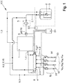
- FIG. 4 shows a fuel supply system 100 which is equipped with a volume flow-based, pump-synchronous, in particular cylinder-selective, rail pressure control according to FIGS Figure 2A and 2 B is operated.
- a high-pressure pump 1 is supplied with fuel from a fuel tank 3 by a pre-feed pump 2 via a low-pressure line 2.1.
- a filter unit 5 is located in the low-pressure line 2.1 and a dual sensor 6, which measures pressure p6 and temperature T6 upstream of the high-pressure pump 1 in the low-pressure line 2.1, is arranged.
- the high-pressure pump 1 pumps fuel via a high-pressure line 1.4 into a fuel reservoir, in particular into a fuel rail 4.
- the fuel rail 4 includes a rail pressure sensor 7, which detects the rail pressure p7 in the fuel rail 4.
- the fuel rail 4 also includes a pressure regulating valve 8 which, within the method, diverts a predeterminable volume flow V8 into the low-pressure line 2.1 from the fuel rail 4 via a return line 8.2.1.
- the injectors 9n have leakage lines which open into a common return line 9.3.
- the return line 9.3 opens into a high pressure pump return line 1.3 of the high pressure pump 1, which leads back to the fuel tank 3.
- a control unit S1 in particular an engine control unit, is directly connected to the duo sensor 6, the high pressure pump 1, the pressure control valve 8, the rail pressure sensor 7 and the injectors 91, 92, 93, 94 and in the exemplary embodiment indirectly via control lines (without reference symbols) a control unit S2 is connected to the prefeed pump 2 designed as a low-pressure pump.
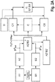
- the Figure 2A shows the volume flow-based pump-synchronous control structure for rail pressure control in the basic concept, which is stored in an electronic control device, in particular control device S1, which is set up to carry out one of the methods presented above.
- the control device S1 and the control device S2 are operated via a computer program for executing the method, a machine-readable storage medium with the computer program recorded thereon being provided on the computer.
- volume flow-based pump-synchronous control structure for rail pressure control is based on the Figure 2A explained in detail below.
- the rail pressure sensor 7 gives the control loop consisting of a pilot control model, a controller and an actuator of the high pressure pump 1 the corresponding pressure information.
- the input variable of the method for operating the fuel supply system 100 according to the invention is a specific volume flow which is supplied to the high pressure pump 1 or discharged through the pressure regulating valve 8.
- the object of the invention is thus that the complete high-pressure regulation, i.e. the rail pressure high-pressure regulation within the rail 4 of the fuel supply system 100, from a time-based cyclical calculation of a rail pressure regulator for regulating the rail pressure in the rail 4 to a volume flow-based and pump-synchronous based on the engine segment of the internal combustion engine discrete calculation for rail pressure control (in a two-digit concept pressure control valve control and high pressure pump control) is converted.
- the pressure information p7 actual from the rail pressure sensor 7 of an engine-synchronous / pump-synchronous segment is compared with the target rail pressure p7 target of the preceding engine-synchronous / pump-synchronous segment (one speaks of the delayed target rail pressure) in order to determine the discrete control deviation ⁇ p7.
- This pressure difference ⁇ p7 is converted into a volume difference via the modulus of elasticity E of the fuel and via the fuel temperature T6 determined by means of the duo sensor 6 and processed as an input variable ⁇ V Rail in a control system.
- This volume difference ⁇ V Rail is calculated with the aid of the digital metering unit (not shown), which is preferably arranged in the pump chamber of the high-pressure pump 1, or by controlling the Pressure regulating valve 8 is supplied as an input variable to the controlled system and the actuators of high pressure pump 1 or pressure regulating valve 8 are activated, whereby the discretization, i.e. the calculation of the volume difference ⁇ V Rail for each motor segment can be varied pump-synchronously.
- the volume balance of the volume flow-based segment-synchronous calculation is based on a volume-constant room volume V H of the high-pressure system in which there is a certain volume of fuel, depending on the pressure, which is basically supplied via the high-pressure pump 1 and discharged via the pressure control valve 1.
- the volumes a) and b) are taken on an event-related basis, while c) the permanent fuel leakage V DLeck of the high-pressure system is discretized via a Z transformation.
- there is an event-related discretization of the permanent leakage V DLeck of the high pressure system so that the volumes a), b), c) can be added accordingly as taken from the high pressure system as the total volume V Ges-Ab taken .
- the so-called load and / or speed-dependent change request for the rail pressure the so-called pressure change request (also referred to as the dynamic volume flow component) within the rail 4, which is generated by the supply of fuel volume (pressure increase) via the high-pressure pump 1 as a V ⁇ p rail specification or by discharging fuel volume (pressure reduction) via the pressure control valve 8 within the volume balance as a V ⁇ p-rail specification .
- the high-pressure pump 1 has, in a known manner and advantageously, a fixed assignment of the pump TDC segment synchronous / cylinder synchronous every 180 ° crank angle of the internal combustion engine to the cylinder piston TDCs of the cylinder pistons (not shown) of the internal combustion engine, the engine speed corresponding to the high pressure pump speed.
- a certain fixed offset can exist between the pump TDC and the cylinder piston TDC, but this is known and can be taken into account accordingly in the fixed assignment.
- the calculation according to the invention takes place via a trigger start signal nsync (cf. Figures 2A and 2 B and Figure 3 ), the calculation being segment-synchronous / cylinder-synchronous every 180 ° crank angle, with the calculation of the sizes of the controlled system for each of the cylinders or the associated injectors 9n which inject into this cylinder being carried out separately.
- nsync cf. Figures 2A and 2 B and Figure 3
- the volume flow-based pump-synchronous control structure for regulating the rail pressure of the high-pressure pump 1 comprises a signal acquisition module B1 for signal acquisition of the rail pressure p7 by means of the rail pressure sensor 7.
- the detection of the rail pressure p7 takes place synchronously within the module B1 for the signal detection of the rail pressure p7 in a measurement grid in ms steps, with an actual value being discrete segment-synchronously within the segment within the module B2, which is called the actual value discretization module p7 Isl as the minimum pressure p 7 is-min and a maximum pressure p 7 is-max detected and stored, wherein from these pressures p 7 is-min, p 7lst-max also as an actual value p7 lsl an average p7 actual 50% of the Press P 7Ist-min , p 7lst-max is calculated within the segment and also saved.
- the volume flow-based pump-synchronous control structure for the rail pressure control of the high-pressure pump 1 includes a setpoint specification module A1 for the setpoint specification of the rail pressure p7 Soll, which is stored in the form of map data in the computer program of the engine control unit, which stems from the respective combustion process applied and is specified.
- this target rail pressure p7 target is also discretized by any current default time grid, that is, a conversion takes place from the time “slice” to the segment "slice” at time nsync (trigger start signal), ie at the start of the calculation .
- target rail pressure p7 target is "frozen" at the beginning of a time slice of the segment at time nsync
- This procedure is necessary because the system always has a time delay.
- the control value of a pilot control generates an increase in volume flow into the rail after the pump has delivered. Therefore it becomes the Difference formation used setpoint p7 Soll delayed by exactly one work cycle and compared with the actual value p7 lsl of the following work cycle .
- the minimum pressure p 7min or the maximum jerk p 7max or the mean value p7 50% are available as the discrete actual value p7 lsl .
- the corresponding pressure-related calculation is carried out in the control error calculation module A2 / B2 (cf. Figure 2A ) in which the discretized setpoint rail pressure values p7 setpoint and the discretized actual rail pressure values p7 lsl enter and are compared segment-synchronously and output and stored calculated as a control error.
- a conversion into a volume flow-based control difference ⁇ V Rail i.e. a volume flow difference with the resolution of a differential equation, is carried out, where E is is pressure- and temperature-dependent specific modulus of elasticity of the respective fuel and V H , as explained above, the volume of space of the high-pressure fuel system of the fuel supply system 100.
- ⁇ V Rail V H E. p T ⁇ ⁇ p Rail
- This conversion into the segment-synchronous volume error ⁇ V Rail has the advantage that the non-linear fuel properties of the fuel are taken into account in the control.
- the non-linear properties of the fuel with regard to pressure and temperature and compressibility are not mapped in pressure-based systems
- the advantage of the present method is that these non-linearities are taken into account by converting them into the segment-synchronous volume error ⁇ V Rail .
- a discrete volume control difference ⁇ V Rail is available due to the features of the basic concept described, which is used directly for the volume flow-based actuators E1, E8 (high pressure pump 1 and pressure control valve 8).
- the controller module C, C1, C8 comprises, as a sub-module, a controller state machine C which, depending on the requirements, determines the pressure based on the volume flow / volume flow, i.e. depending on the discrete volume control difference ⁇ V determined in the conversion module A2 '/ B2' Rail increases or decreases, and it decides whether a control intervention via a PID controller module C1 of high-pressure pump 1 (cf. Figure 2A ) "pressure increasing" or via a PID controller module C8 of the pressure control valve 8 "pressure decreasing".
- the structure also includes according to Figure 2A a pre-control volume flow value module D as a fault controller for the segment-synchronous volume flow-based pre-control (reference variable with disturbance variable compensation) of the fuel supply system, the reference variable of which is merged with the PID controller module C1 of the high-pressure pump 1 and the PID controller module C8 of the pressure control valve 8, so that the PID controller modules C1, C8 only have to compensate for the control fluctuations of the fuel supply system.
- a pre-control volume flow value module D as a fault controller for the segment-synchronous volume flow-based pre-control (reference variable with disturbance variable compensation) of the fuel supply system, the reference variable of which is merged with the PID controller module C1 of the high-pressure pump 1 and the PID controller module C8 of the pressure control valve 8, so that the PID controller modules C1, C8 only have to compensate for the control fluctuations of the fuel supply system.
- the pre-control volume flow value module D is added as pilot control variables to the segment-synchronous volume flows mentioned under a) to d), so that the control system is already managed in the pre-control volume flow value module D.
- the values of the fault controller of the precontrol volume flow value module D which are regulated by the PID controller modules C1, C8 (see Fig Figure 2 ) to an output module E, which electrically controls the actuators E1 and E8 of the high pressure pump 1 and the pressure control valve 8 and adjusts the actuators E1 and E8 as required via the controlled system based on the pump segment and based on volume.
- n number of cylinders or the associated injectors 9n (cf. Figure 1 )
- a separate cylinder-selective control deviation ⁇ V Rail in particular a proportional component and / or an integrator component and / or a differential component, is calculated and, according to the cylinder-selective control deviation ⁇ V Rail , the control values E1, E8 cylinder for cylinder or injector for injector 9n or Injection valve for injection valve selected segment-synchronously and, as explained above, output based on volume flow for high-pressure pump 1 or pressure control valve 8.
- the injectors 9n receive the same quantity setpoints from cylinder to cylinder in stationary operation, but different quantity decreases V 9n result from the rail 4 due to injector scatter, according to the invention, for example, the individual integrator components of the cylinder-selective controllers C1 n , C8 n show the quantity deviations between the injectors 9 n , which can have various causes. Depending on the type of quantity discrepancy, the causes can be assigned to specific error groups with a high degree of probability.
- a discrete volume control difference ⁇ V Rail is available as an input variable for a controller module C, C1, C8 in the basic concept according to the invention, which is used directly for the volume flow-based actuators E1, E8 (high pressure pump 1 and pressure control valve 8), with segment-synchronous for every cylinder or injector 9n "only one" control structure is used repeatedly.
- the so-called “cylinder-selective control” in which several control structures are cylinder-selective (cf. Figure 2B ) are used, is explained in more detail below.
- a segment-synchronous discrete volume control difference ⁇ V Rail is available as an input variable for several (n) controller modules C1n, C8n, which according to the extension "cylinder-selective" directly for the volume flow-based actuators E1, E8 (high pressure pump 1 and pressure control valve 8 ) is used.
- the structure also includes according to Figure 2B a pre-control volume flow value module D as a fault controller for the segment-synchronous volume flow-based pre-control (reference variable with disturbance variable compensation) of the fuel supply system 100, the reference variable of which is combined with the PID controller module C1n of the high-pressure pump 1 and the PID controller module C8n of the pressure control valve 8, so that the PID controller modules C1n, C8n only have to compensate for the control fluctuations of the fuel supply system.
- a pre-control volume flow value module D as a fault controller for the segment-synchronous volume flow-based pre-control (reference variable with disturbance variable compensation) of the fuel supply system 100, the reference variable of which is combined with the PID controller module C1n of the high-pressure pump 1 and the PID controller module C8n of the pressure control valve 8, so that the PID controller modules C1n, C8n only have to compensate for the control fluctuations of the fuel supply system.
- the high-pressure control can now - as an extension of the basic concept - be performed on a cylinder-specific basis by means of the cylinder-selective control, i.e. for each cylinder or each injection process an adapted, cylinder-specific corrected manipulated variable is output as actuator output E1 of high-pressure pump 1 or actuator output E8 of pressure regulating valve 8.
- the respective PID controller modules C1n, C8n can each be evaluated separately and calibrated.
- the evaluation of the four individual PID controller modules C1n or C8n in the exemplary embodiment i.e. the comparison of the integrator components and proportional components that are different in steady-state operation, for example, allows a cylinder-related or injector-related error analysis and cause grouping, on the one hand Simple diagnostic function (on-board diagnosis without expansion) or a diagnostic function (on-board diagnosis without expansion) with a correction function is provided.
- a specific cylinder-related or injector-related error can be permitted up to a predefinable threshold value via the diagnostic function, and a cylinder-related or injector-related error correction only takes place after the threshold value has been exceeded.
- the injection quantity errors advantageously calling for replacement of the defective injector 9n within the on-board diagnosis or within the cylinder-selective Regulation can be taken into account and corrected.
- the cylinder-selective control information that is to say the individual injection quantity errors of the individual injectors 9n, can generally be adapted and used to improve the pilot control D of the injectors 9n.
- the respective cylinder-selective controlled variable C1n, C8n can also advantageously be converted into another reference variable, with particular consideration being given to the internal engine torque of the respective cylinder, so that a cylinder-selective torque-dependent control is made possible through the support of the cylinder-selective rail pressure control, in which the cylinder-selective control information in particular can be used for torque-cylinder equalization by, for example, transferring a corresponding pilot control value from the cylinder-selective rail pressure regulation to a cylinder-selective torque controller.
- the high-pressure control in the described non-cylinder-selective control or in the described cylinder-selective control outputs an adapted corrected manipulated variable in an actuator output E1 of the high-pressure pump 1 or in an actuator output E8 of the pressure control valve 8.
- PWM pulse width modulation
- AD converter analog-to-digital converter
- PWM-synchronous current recording systems in which a hardware filter with a high cut-off frequency is used to eliminate high-frequency interference, have the following disadvantages: A mean value-free acquisition cannot be performed. Sampling takes place in the frequency range of the HW filter with a high CPU load because the sampling frequency is coupled to the PWM base frequency. With small PWM duty cycles, aliasing errors can lead to undersampling, which leads to a shift in the mean value. The procedure is therefore rarely used.
- Time-synchronous current acquisition systems in which a HW filter with a low cut-off frequency is used to smooth the PWM oscillation on the current signal have the following Disadvantages: Due to the low cutoff frequency and high filter time constant, these HW filters have a high phase shift. The controller must be adapted to a relatively slow HW filter. The time-synchronous current detection systems also show poor control behavior in the event of malfunctions, because the actual value reaches the controller with a delay due to the slow HW filtering.
- the voltage drop across the measuring resistor is used with the help of a measuring resistor to determine the current in the actuator.
- This value is recorded cyclically by means of an AD converter and made available to the current control as an actual value.
- This current measured value is regulated in a closed control loop.
- this measured value must be filtered in front of the analog / digital converter using an analog hardware (HW) low-pass filter with a corresponding limit frequency (usually between 10 Hz and 50 Hz with time-synchronous current measurement).
- HW analog hardware
- This filter is usually an RC element.
- the actuators for the actuator output E1, E8 of the high pressure pump 1 and of the pressure control valve 8 of the high pressure control are the inner control loops, whereby the actual hydraulic pressure control already explained (compare the components of the hydraulic pressure control in the Figures 2A and 2 B and the associated description) represent the outer control loops.
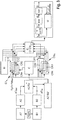
- the solution according to the invention consists in a modified signal processing or signal processing chain, which according to the invention includes an in Figure 3 includes observer model shown.
- an observer module W is arranged integrated in the signal processing chain and is advantageously used in the signal processing chain to control components 1 and 8.
- This observer W integrated in the signal processing chain improves the current detection of the high pressure pump 1 and the pressure control valve 8 and their current control in the described non-cylinder-selective rail pressure control and in the cylinder-selective rail pressure control.
- the current detection is improved by means of the observer model in such a way that the delay times and phase shifts of the current detection, which are caused by the analog filtering (HW filter) of the signal, are circumvented, with the model ensuring that the observer W is constantly tracked by converging a so-called observation error to zero, the observation error being defined as the difference between the measured value and the observed value.
- HW filter analog filtering
- the current detection system according to the invention is shown in Figure 3 arranged in the output module component E and in Figure 3 in a schematically illustrated system diagram extracted from the output module component E.
- the system according to the invention for current detection is based on time-synchronous current detection and a so-called state reconstruction or state vector construction.
- the system diagram extracted from output module component E illustrates a voltage value u (which corresponds to a pulsating coil current or a pulsating coil voltage of a conventional PWM-synchronous current measurement), which represents the input variable of the system for current measurement.
- the voltage u represents the input variable that of the coil 1 Ls + R. the control unit of the components 1, 8 to be controlled is supplied.
- the output of the coil 1 Ls + R. is a current value i 1, known as the effective value of the coil 1 Ls + R. is sought as a control current for controlling the components 1, 8, which cannot be measured by measurement without appropriate processing of the signal.
- the current value i 1 or the effective value of the coil 1 Ls + R. represents the input variable for a hardware filter HW for filtering the current value i 1 , which in turn outputs the current value i 2 , which finally represents the input variable for a software filter SW for damping the signal of the current value i 2 in the control unit, so that after this Signal processing chain a signal of a current value i 3 is available.
- the voltage value u thus represents the input value into the observer module W, the current value i 3 representing the output value of the signal processing chain, which is also made available to the observer module W, the observer module W via the underlying observer Model calculates a new voltage value u in parallel to the signal processing chain explained above.
- the observer W is continuously tracked in that the so-called observation error converges to zero, the observation error being defined as the difference between the measured value i1 and the observed value i3.
- This solution according to the invention enables a high performance and stability of the current detection corresponding to the requirements, whereby the inner current control loops with high performance are to be understood in detail as the following advantageous properties of the current detection according to the invention by means of observer W:
- This type of current detection has only a slight phase shift there on the
- the model value of the observer is regulated, which corresponds to the real current value which, however, due to the disadvantages of the phase response of the filtering, would only be recorded after the filter run time.
- the acquisition with observer is faster, so that ultimately the control based on it is also faster.
- the current detection according to the invention does not require averaging, that is to say it is more accurate in particular in contrast to the PWM-synchronous current detection (with averaging) that is used on all sides.
- no aliasing effects occur, that is to say incorrect signal determination with undersampling, as is the case with other current detection methods, does not occur.
Applications Claiming Priority (6)
| Application Number | Priority Date | Filing Date | Title |
|---|---|---|---|
| DE102019118932 | 2019-07-12 | ||
| DE102019118914 | 2019-07-12 | ||
| DE102019118923 | 2019-07-12 | ||
| DE102019129323.5A DE102019129323A1 (de) | 2019-07-12 | 2019-10-30 | Verfahren zur volumenstrombasierten pumpensynchronen und zylinderselektiven Raildruckregelung für ein Kraftstoffversorgungssystem einer Brennkraftmaschine |
| DE102019129306.5A DE102019129306A1 (de) | 2019-07-12 | 2019-10-30 | Verfahren zur Stromerfassung und Stromregelung der Stellglieder einer volumenstrombasierten pumpensynchronen nichtzylinderselektiven oder zylinderselektiven Raildruckregelung für ein Kraftstoffversorgungssystem einer Brennkraftmaschine |
| DE102019129320.0A DE102019129320A1 (de) | 2019-07-12 | 2019-10-30 | Verfahren zur volumenstrombasierten pumpensynchronen Raildruckregelung für ein Kraftstoffversorgungssystem einer Brennkraftmaschine |
Publications (2)
| Publication Number | Publication Date |
|---|---|
| EP3763933A1 true EP3763933A1 (fr) | 2021-01-13 |
| EP3763933B1 EP3763933B1 (fr) | 2023-11-15 |
Family
ID=71527664
Family Applications (1)
| Application Number | Title | Priority Date | Filing Date |
|---|---|---|---|
| EP20184711.8A Active EP3763933B1 (fr) | 2019-07-12 | 2020-07-08 | Procédé de réglage de la pression de rampe basé sur le débit volumique synchronique de pompe, en particulier sélective par cylindre pour un système d'alimentation en carburant d'une machine à combustion interne avec mesure de courant et régulation de courant des organes de réglage de la pression de rampe |
Country Status (1)
| Country | Link |
|---|---|
| EP (1) | EP3763933B1 (fr) |
Cited By (1)
| Publication number | Priority date | Publication date | Assignee | Title |
|---|---|---|---|---|
| CN113153556A (zh) * | 2021-05-13 | 2021-07-23 | 潍柴动力股份有限公司 | 一种轨压控制方法和装置 |
Citations (5)
| Publication number | Priority date | Publication date | Assignee | Title |
|---|---|---|---|---|
| EP1710638A1 (fr) * | 2005-04-07 | 2006-10-11 | HONDA MOTOR CO., Ltd. | Contrôleur |
| DE102008041577A1 (de) * | 2007-08-31 | 2009-04-09 | Denso Corp., Kariya-shi | Kraftstoffdrucksteuergerät für eine Brennkraftmaschine |
| DE102011004031A1 (de) * | 2011-02-14 | 2012-08-16 | Continental Automotive Gmbh | Einspritzsystem für eine Brennkraftmaschine |
| DE102016204386A1 (de) | 2016-03-16 | 2017-09-21 | Robert Bosch Gmbh | Verfahren zum Regeln eines durch eine Hochdruckpumpe bewirkten Kraftstoffraildrucks |
| DE102016211128A1 (de) * | 2016-06-22 | 2017-12-28 | Robert Bosch Gmbh | Verfahren zum volumenstrombasierten Regeln eines durch eine Hochdruckpumpe bewirkten Kraftstoffraildrucks |
-
2020
- 2020-07-08 EP EP20184711.8A patent/EP3763933B1/fr active Active
Patent Citations (5)
| Publication number | Priority date | Publication date | Assignee | Title |
|---|---|---|---|---|
| EP1710638A1 (fr) * | 2005-04-07 | 2006-10-11 | HONDA MOTOR CO., Ltd. | Contrôleur |
| DE102008041577A1 (de) * | 2007-08-31 | 2009-04-09 | Denso Corp., Kariya-shi | Kraftstoffdrucksteuergerät für eine Brennkraftmaschine |
| DE102011004031A1 (de) * | 2011-02-14 | 2012-08-16 | Continental Automotive Gmbh | Einspritzsystem für eine Brennkraftmaschine |
| DE102016204386A1 (de) | 2016-03-16 | 2017-09-21 | Robert Bosch Gmbh | Verfahren zum Regeln eines durch eine Hochdruckpumpe bewirkten Kraftstoffraildrucks |
| DE102016211128A1 (de) * | 2016-06-22 | 2017-12-28 | Robert Bosch Gmbh | Verfahren zum volumenstrombasierten Regeln eines durch eine Hochdruckpumpe bewirkten Kraftstoffraildrucks |
Cited By (1)
| Publication number | Priority date | Publication date | Assignee | Title |
|---|---|---|---|---|
| CN113153556A (zh) * | 2021-05-13 | 2021-07-23 | 潍柴动力股份有限公司 | 一种轨压控制方法和装置 |
Also Published As
| Publication number | Publication date |
|---|---|
| EP3763933B1 (fr) | 2023-11-15 |
Similar Documents
| Publication | Publication Date | Title |
|---|---|---|
| DE102012102336B4 (de) | Vorrichtung zum Abschätzen eines Kraftstoffeinspritzzustands | |
| EP3698032B1 (fr) | Procédé de commande et de régulation d'un moteur à combustion interne sur la base de modèles | |
| EP1716331A1 (fr) | Procede de synchronisation des cylindres en termes de quantites d'injection de carburant dans un moteur thermique | |
| DE102018110898A1 (de) | Verfahren zur Steuerung der Kraftstoffeinspritzung in Dieselmotoren | |
| DE112015002823T5 (de) | System und Verfahren zur Einspritzdüsensteuerung für Mehrfachimpuls-Kraftstoffeinspritzung | |
| DE102014217582A1 (de) | Verfahren zur Steuerung der Kraftstoffeinspritzung und Common-Rail-Einspritz- und Steuerungssysteme | |
| WO2015051865A1 (fr) | Procédé permettant de faire fonctionner un moteur à combustion interne, procédé de commande et de régulation d'un moteur à combustion interne, système d'injection et moteur à combustion interne | |
| DE102008000772A1 (de) | Common-Rail-Kraftstoffeinspritzvorrichtung und Verfahren zum Kompensieren einer Pumpkennlinie einer Hochdruckpumpe | |
| DE10303765B4 (de) | Sammlereinspritzsystem | |
| DE102010008762A1 (de) | Verfahren und Vorrichtung zum Steuern des Kraftstoffverteilerrohrdrucks unter Verwendung eines Kraftstoffdrucksensorfehlers | |
| EP2142785A1 (fr) | Procédé et dispositif de commande d'injection d'un moteur à combustion interne | |
| DE102017217113A1 (de) | Verfahren zum Betreiben eines Verbrennungsmotors und elektronisches Steuergerät für einen Verbrennungsmotor | |
| DE112013002475B4 (de) | Kraftstoffeinspritzungs-Steuer- und Regelungsvorrichtung und Kraftstoffeinspritzungs-Steuer- und Regelungsverfahren für Verbrennungsmotor | |
| EP3763933B1 (fr) | Procédé de réglage de la pression de rampe basé sur le débit volumique synchronique de pompe, en particulier sélective par cylindre pour un système d'alimentation en carburant d'une machine à combustion interne avec mesure de courant et régulation de courant des organes de réglage de la pression de rampe | |
| WO2008092779A1 (fr) | Procédé et dispositif de correction de l'injection de carburant | |
| DE102014209298B4 (de) | Kraftstoffeinspritzeigenschaftserfassungssystem | |
| DE102019129306A1 (de) | Verfahren zur Stromerfassung und Stromregelung der Stellglieder einer volumenstrombasierten pumpensynchronen nichtzylinderselektiven oder zylinderselektiven Raildruckregelung für ein Kraftstoffversorgungssystem einer Brennkraftmaschine | |
| WO2014202202A1 (fr) | Procédé et dispositif de commande permettant de corriger la durée d'injection des injecteurs d'un moteur à combustion interne | |
| DE102014211314A1 (de) | Verfahren zum Korrigieren einer pumpenverursachten Abweichung einer Ist-Einspritzmenge von einer Soll-Einspritzmenge | |
| DE102009041060A1 (de) | Verfahren zum Betrieb einer Verbrennungskraftmaschine | |
| WO2014202201A1 (fr) | Procédé et système de commande de correction du début d'injection des injecteurs d'un moteur à combustion interne | |
| EP3371442A1 (fr) | Moteur à combustion interne à diagnostic d'injecteur de carburant | |
| DE102013105355B4 (de) | Kraftstoffeinspritzungssteuervorrichtung, die für Mehrfacheinspritzung optimiert ist | |
| DE102011100108B4 (de) | Bestimmung einer Einspritzventilkennlinie und Verringerung eines Einspritzmengenunterschieds bei einem Verbrennungsmotor | |
| DE10305525B4 (de) | Verfahren und Vorrichtung zur Adaption der Druckwellenkorrektur in einem Hochdruck-Einspritzsystem eines Kraftfahrzeuges im Fahrbetrieb |
Legal Events
| Date | Code | Title | Description |
|---|---|---|---|
| PUAI | Public reference made under article 153(3) epc to a published international application that has entered the european phase |
Free format text: ORIGINAL CODE: 0009012 |
|
| STAA | Information on the status of an ep patent application or granted ep patent |
Free format text: STATUS: THE APPLICATION HAS BEEN PUBLISHED |
|
| AK | Designated contracting states |
Kind code of ref document: A1 Designated state(s): AL AT BE BG CH CY CZ DE DK EE ES FI FR GB GR HR HU IE IS IT LI LT LU LV MC MK MT NL NO PL PT RO RS SE SI SK SM TR |
|
| AX | Request for extension of the european patent |
Extension state: BA ME |
|
| STAA | Information on the status of an ep patent application or granted ep patent |
Free format text: STATUS: REQUEST FOR EXAMINATION WAS MADE |
|
| 17P | Request for examination filed |
Effective date: 20210713 |
|
| RBV | Designated contracting states (corrected) |
Designated state(s): AL AT BE BG CH CY CZ DE DK EE ES FI FR GB GR HR HU IE IS IT LI LT LU LV MC MK MT NL NO PL PT RO RS SE SI SK SM TR |
|
| GRAP | Despatch of communication of intention to grant a patent |
Free format text: ORIGINAL CODE: EPIDOSNIGR1 |
|
| STAA | Information on the status of an ep patent application or granted ep patent |
Free format text: STATUS: GRANT OF PATENT IS INTENDED |
|
| RIC1 | Information provided on ipc code assigned before grant |
Ipc: F02M 63/02 20060101ALN20230525BHEP Ipc: F02M 59/36 20060101ALN20230525BHEP Ipc: F02D 41/14 20060101ALN20230525BHEP Ipc: F02D 41/00 20060101ALI20230525BHEP Ipc: F02D 41/38 20060101AFI20230525BHEP |
|
| INTG | Intention to grant announced |
Effective date: 20230619 |
|
| P01 | Opt-out of the competence of the unified patent court (upc) registered |
Effective date: 20230710 |
|
| GRAS | Grant fee paid |
Free format text: ORIGINAL CODE: EPIDOSNIGR3 |
|
| GRAA | (expected) grant |
Free format text: ORIGINAL CODE: 0009210 |
|
| STAA | Information on the status of an ep patent application or granted ep patent |
Free format text: STATUS: THE PATENT HAS BEEN GRANTED |
|
| AK | Designated contracting states |
Kind code of ref document: B1 Designated state(s): AL AT BE BG CH CY CZ DE DK EE ES FI FR GB GR HR HU IE IS IT LI LT LU LV MC MK MT NL NO PL PT RO RS SE SI SK SM TR |
|
| REG | Reference to a national code |
Ref country code: CH Ref legal event code: EP Ref country code: GB Ref legal event code: FG4D Free format text: NOT ENGLISH |
|
| REG | Reference to a national code |
Ref country code: DE Ref legal event code: R096 Ref document number: 502020006008 Country of ref document: DE |
|
| REG | Reference to a national code |
Ref country code: IE Ref legal event code: FG4D Free format text: LANGUAGE OF EP DOCUMENT: GERMAN |
|
| REG | Reference to a national code |
Ref country code: LT Ref legal event code: MG9D |
|
| REG | Reference to a national code |
Ref country code: NL Ref legal event code: MP Effective date: 20231115 |
|
| PG25 | Lapsed in a contracting state [announced via postgrant information from national office to epo] |
Ref country code: GR Free format text: LAPSE BECAUSE OF FAILURE TO SUBMIT A TRANSLATION OF THE DESCRIPTION OR TO PAY THE FEE WITHIN THE PRESCRIBED TIME-LIMIT Effective date: 20240216 |
|
| PG25 | Lapsed in a contracting state [announced via postgrant information from national office to epo] |
Ref country code: IS Free format text: LAPSE BECAUSE OF FAILURE TO SUBMIT A TRANSLATION OF THE DESCRIPTION OR TO PAY THE FEE WITHIN THE PRESCRIBED TIME-LIMIT Effective date: 20240315 |
|
| PG25 | Lapsed in a contracting state [announced via postgrant information from national office to epo] |
Ref country code: LT Free format text: LAPSE BECAUSE OF FAILURE TO SUBMIT A TRANSLATION OF THE DESCRIPTION OR TO PAY THE FEE WITHIN THE PRESCRIBED TIME-LIMIT Effective date: 20231115 |
|
| PG25 | Lapsed in a contracting state [announced via postgrant information from national office to epo] |
Ref country code: NL Free format text: LAPSE BECAUSE OF FAILURE TO SUBMIT A TRANSLATION OF THE DESCRIPTION OR TO PAY THE FEE WITHIN THE PRESCRIBED TIME-LIMIT Effective date: 20231115 |
|
| PG25 | Lapsed in a contracting state [announced via postgrant information from national office to epo] |
Ref country code: ES Free format text: LAPSE BECAUSE OF FAILURE TO SUBMIT A TRANSLATION OF THE DESCRIPTION OR TO PAY THE FEE WITHIN THE PRESCRIBED TIME-LIMIT Effective date: 20231115 |
|
| PG25 | Lapsed in a contracting state [announced via postgrant information from national office to epo] |
Ref country code: NL Free format text: LAPSE BECAUSE OF FAILURE TO SUBMIT A TRANSLATION OF THE DESCRIPTION OR TO PAY THE FEE WITHIN THE PRESCRIBED TIME-LIMIT Effective date: 20231115 Ref country code: LT Free format text: LAPSE BECAUSE OF FAILURE TO SUBMIT A TRANSLATION OF THE DESCRIPTION OR TO PAY THE FEE WITHIN THE PRESCRIBED TIME-LIMIT Effective date: 20231115 Ref country code: IS Free format text: LAPSE BECAUSE OF FAILURE TO SUBMIT A TRANSLATION OF THE DESCRIPTION OR TO PAY THE FEE WITHIN THE PRESCRIBED TIME-LIMIT Effective date: 20240315 Ref country code: GR Free format text: LAPSE BECAUSE OF FAILURE TO SUBMIT A TRANSLATION OF THE DESCRIPTION OR TO PAY THE FEE WITHIN THE PRESCRIBED TIME-LIMIT Effective date: 20240216 Ref country code: ES Free format text: LAPSE BECAUSE OF FAILURE TO SUBMIT A TRANSLATION OF THE DESCRIPTION OR TO PAY THE FEE WITHIN THE PRESCRIBED TIME-LIMIT Effective date: 20231115 Ref country code: BG Free format text: LAPSE BECAUSE OF FAILURE TO SUBMIT A TRANSLATION OF THE DESCRIPTION OR TO PAY THE FEE WITHIN THE PRESCRIBED TIME-LIMIT Effective date: 20240215 Ref country code: PT Free format text: LAPSE BECAUSE OF FAILURE TO SUBMIT A TRANSLATION OF THE DESCRIPTION OR TO PAY THE FEE WITHIN THE PRESCRIBED TIME-LIMIT Effective date: 20240315 |